EP2386367A2 - Vorrichtung zur Entformung in Sandgießform erstarrter Gussteile - Google Patents
Vorrichtung zur Entformung in Sandgießform erstarrter Gussteile Download PDFInfo
- Publication number
- EP2386367A2 EP2386367A2 EP11003678A EP11003678A EP2386367A2 EP 2386367 A2 EP2386367 A2 EP 2386367A2 EP 11003678 A EP11003678 A EP 11003678A EP 11003678 A EP11003678 A EP 11003678A EP 2386367 A2 EP2386367 A2 EP 2386367A2
- Authority
- EP
- European Patent Office
- Prior art keywords
- castings
- sand
- support
- sandgießformballen
- bales
- Prior art date
- Legal status (The legal status is an assumption and is not a legal conclusion. Google has not performed a legal analysis and makes no representation as to the accuracy of the status listed.)
- Granted
Links
Images
Classifications
-
- B—PERFORMING OPERATIONS; TRANSPORTING
- B22—CASTING; POWDER METALLURGY
- B22D—CASTING OF METALS; CASTING OF OTHER SUBSTANCES BY THE SAME PROCESSES OR DEVICES
- B22D29/00—Removing castings from moulds, not restricted to casting processes covered by a single main group; Removing cores; Handling ingots
Definitions
- the invention relates to a device for demolding in sand cast mold bales of solidified castings, wherein the Sandg discernformballen are successively transported away from a Eing manposition on a support pad.
- the sand casting molds are conventionally run over a grate through which the molding sand falls off the castings. Non-self draining molding sand residues and sprues are removed manually.
- the invention has for its object to reduce the effort for demolding using sand cast mold bales produced castings.
- the castings can be automatically removed from the sand casting mold bales by the device according to the invention and kept ready for further processing in a defined starting position.
- the support base extends at least to a disintegration position of the sand mold bales in which the material of the sand mold bales drops from the casting received by the support rail.
- the disintegration position may e.g. be determined by an end edge of the carrier pad. Alternatively or additionally, shaking or pushing devices could be used at this point.
- a plurality of mutually parallel support rails are provided, wherein the castings are in particular suspended between the support rails, preferably via a gate widening, e.g. via a sprue cone produced by a funnel-shaped sprue opening.
- the castings can be easily pushed onto such a pair of retaining rails arranged at a distance from one another.
- the carrier pad can form a slideway on which the Sandg cordformballen are adjacent to each other displaced.
- a carrier support which itself is movable would be usable, e.g. a conveyor belt.
- the castings are slidably moved on the support rail as a result of the transport of the sand mold bales enclosing the castings.
- the trailing Sandg discernformballen push the exposed after disintegration of Sandg discernformballen then castings on the support rails on.
- the castings can be transported away beyond the other end of the carrier rail for further processing.
- the removal can take place with rotation of the castings about a vertical axis, by 90 °.
- the castings can be brought into a suitable position for further processing.
- the castings of a separating device for the separation of sprues can be supplied, wherein such a separator, for example, a shearing with a Includes die and a stamp.
- a separator for example, a shearing with a Includes die and a stamp.
- the punch pushes the casting, shearing the sprues through an opening in the die.
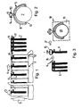
- Sandgitformballen 1 are transported on a support base 2 from a Eing manposition 3 in a row abutting each other according to arrow 4.
- the support base 2 forms a slideway on which the Sandg screenformballen 1 are advanced by means of a schematically indicated by an arrow 5 transport device cyclically.
- approximately cuboid Sandg screenformballen 1 is poured in the Eing manposition at 3 casting material, which is in the relevant embodiment to the production cast clutch plates for vehicle clutches.
- the solidifying in the Sandg discernformballen 1 castings 6 include in addition to the vertically inside the Sandg collectformballens extending clutch disc 7 Angusstraube 8 with a cone formed by a funnel-shaped sprue 9. At the transition points between the clutch disc 7 and Angusstraube 8 each have a predetermined breaking point 10 is formed.
- the Angusstraube 8 further comprises an extending in the transport direction approach 11, which serves as a spacer.
- FIG. 3 can recognize, adjoins the support rails 13,14 another processing device, which includes the sprue cone 9 attaching gripper 15, which take over the castings 6 of the support rails 13,14 and further transported according to arrow 16. During further transport, a 90 ° rotation of the castings 6 takes place about a vertical axis. The castings 6 then pass according to arrow 17 to a separating device 18, which includes a die 19 and a punch 20. The punch 20 moves perpendicular to the clutch disc 7 and pushes the clutch disc with shearing of the predetermined breaking points 10 through the opening of the die 19th
- subsequent further devices may further comprise vibrator means for shaking off residual molding sand, plasters or the like.
- the sprue cone 9 may have lateral flattenings, so that it can be held in rotation by the gripper 15 about the vertical axis.
Landscapes
- Engineering & Computer Science (AREA)
- Mechanical Engineering (AREA)
- Casting Devices For Molds (AREA)
Abstract
Description
- Die Erfindung betrifft eine Vorrichtung zur Entformung in Sandgießformballen erstarrter Gussteile, wobei die Sandgießformballen aufeinanderfolgend auf einer Trägerunterlage von einer Eingießposition abtransportierbar sind.
- Zur Entformung in Sandgießformballen erstarrter Gussteile lässt man die Sandgießformballen herkömmlich über ein Rost laufen, durch das hindurch der Formsand von den Gussteilen abfällt. Nicht von selbst abfallende Formsandreste und Angüsse werden manuell entfernt.
- Der Erfindung liegt die Aufgabe zugrunde, den Aufwand zur Entformung unter Verwendung von Sandgießformballen hergestellter Gussteile zu verringern.
- Diese Aufgabe wird durch eine Vorrichtung der eingangs genannten Art gelöst, welche durch wenigstens eine mit einem Ende entgegen der Transportrichtung in die Sandgießformballen eindringende, die Gussteile aneinander gereiht aufnehmenden Halteschiene gekennzeichnet ist.
- Vorteilhaft können durch die erfindungsgemäße Vorrichtung die Gussteile den Sandgießformballen automatisch entnommen und zur maschinellen Weiterbearbeitung in einer definierten Ausgangsposition bereit gehalten werden.
- Vorzugsweise erstreckt sich die Trägerunterlage wenigstens bis zu einer Zerfallsposition der Sandgießformballen, in der das Material der Sandgießformballen von dem durch die Halteschiene aufgenommenen Gussteil abfällt.
- Die Zerfallsposition kann z.B. durch eine Endkante der Trägerunterlage festgelegt sein. Alternativ oder zusätzlich wären an dieser Stelle Rüttel- oder Stoßeinrichtungen verwendbar.
- Zweckmäßig sind mehrere zueinander parallele Halteschienen vorgesehen, wobei die Gussteile insbesondere zwischen den Haltschienen einhängbar sind, vorzugsweise über eine Angussaufweitung, z.B. über einen durch eine trichterförmige Eingussöffnung hergestellten Angusskonus.
- Auf ein solches Paar zueinander im Abstand angeordneter Halteschienen lassen sich die Gussteile trotz relativ großer Maßtoleranzen der Sandgießformballen und entsprechend großer Schwankungen der Gussteilpositionen problemlos aufschieben.
- Die Trägerunterlage kann eine Gleitbahn bilden, auf der die Sandgießformballen aneinander anliegend verschiebbar sind. Alternativ oder zusätzlich wäre eine als solche selbst bewegbare Trägerunterlage verwendbare, z.B. ein Transportband.
- Während gesonderte Mittel zur Bewegung der aufgenommenen Gussteile auf der Halteschiene vorgesehen sein könnten, werden in einer bevorzugten Ausführungsform der Erfindung die Gussteile auf der Halteschiene infolge des Transports der die Gussteile einschließenden Sandgießformballen gleitend bewegt. Die nachkommenden Sandgießformballen schieben die nach Zerfall der Sandgießformballen dann freiliegenden Gussteile auf die Halteschienen weiter auf. Letztere Ausführungsform kommt der Forderung nach einer möglichst einfachen, in der schmutzbelasteten Umgebung zuverlässig arbeiteten Konstruktion entgegen.
- In einer bevorzugten Ausführungsform der Erfindung sind die Gussteile über das andere Ende der Trägerschiene hinaus zur weiteren Bearbeitung abtransportierbar.
- Insbesondere kann der Abtransport unter Drehung der Gussteile um eine vertikale Achse, um 90 °, erfolgen. Die Gussteile lassen sich so in eine zur weiteren Bearbeitung geeignete Position bringen.
- Vorzugsweise sind die Gussteile einer Trenneinrichtung zur Abtrennung von Angüssen zuführbar, wobei eine solche Trenneinrichtung z.B. eine Abschereinrichtung mit einer Matrize und einem Stempel umfasst. Der Stempel drückt das Gussteil unter Abscherung der Angüsse durch eine Öffnung in der Matrize.
- Die Erfindung wird nachfolgend anhand eines Ausführungsbeispiels und der beiliegenden, sich auf dieses Ausführungsbeispiel beziehenden Zeichnungen weiter erläutert. Es zeigen:
- Fig. 1
- eine Entformungsvorrichtung nach der Erfindung zur Entformung gegossener Kupplungsscheiben in einer Seitenansicht,
- Fig. 2
- eine Detaildarstellung der Vorrichtung von
Fig. 1 in einer zu der Seitenansicht vonFig. 1 um 90 ° gedrehten Seitenansicht, und - Fig. 3
- eine der Vorrichtung von
Fig. 1 nachgeschaltete Einrichtung zum Abtrennen von Angüssen von den entformten Gussteilen. - Sandgießformballen 1 werden auf einer Trägerunterlage 2 aus einer Eingießposition 3 in einer Reihe aneinander anliegend gemäß Pfeil 4 abtransportiert. Die Trägerunterlage 2 bildet eine Gleitbahn, auf der die Sandgießformballen 1 mit Hilfe einer schematisch durch einen Pfeil 5 angedeuteten Transporteinrichtung taktweise vorgeschoben werden. Alternativ oder zusätzlich könnte als Trägerunterlage ein endloses Transportband dienen.
- In die lediglich aus Formsand bestehenden, etwa quaderförmigen Sandgießformballen 1 wird in der Eingießposition bei 3 Gussmaterial eingefüllt, wobei es in dem betreffenden Ausführungsbeispiel um die Herstellung gegossener Kupplungsscheiben für Fahrzeugkupplungen geht. Die in den Sandgießformballen 1 erstarrenden Gussteile 6 umfassen neben der sich innerhalb des Sandgießformballens vertikal erstreckenden Kupplungsscheibe 7 eine Angusstraube 8 mit einem durch eine trichterförmige Eingussöffnung gebildeten Konus 9. An den Übergangsstellen zwischen der Kupplungsscheibe 7 und der Angusstraube 8 ist jeweils eine Sollbruchstelle 10 gebildet. Die Angusstraube 8 umfasst ferner einen sich in Transportrichtung erstreckenden Ansatz 11, der als Abstandhalter dient.
- Oberhalb einer Endkante 12 der Trägerunterlage 2 verlaufen in Transportrichtung der Sandgießformballen 1 zwei Halteschienen 13 und 14, die an sich seitlich nach oben erstreckenden Haltern (nicht gezeigt) befestigt sind.
- Während des Gießbetriebs, in welchem die Sandgießformballen 1 von der Eingussposition 3 taktweise abtransportiert werden, dringen die Halteschienen 13,14 mit einem Ende entgegen der Transportrichtung in die Sandgießformballen 1 ein und untergreifen den eine Angussaufweitung bildenden Angusskonus 9 der Gussteile 6. Die durch die Transporteinrichtung 5 weiter vorgeschobenen Sandgießformballen erreichen schließlich die Endkante 12 der Trägerunterlage 2, an welcher sich das Material der Sandgießformballen 1 durch seine Schwerkraft von den Gussteilen 6 lösen kann. Die auf den Halteschienen 13,14 gleitenden Gussteile 6 werden, wie dies in
Fig. 1 gezeigt ist, auf den Halteschienen 13,14 aufgereiht, wobei der Ansatz 1 für die Einhaltung eines Abstands zwischen den Gussteilen 6 sorgt. - Wie
Fig. 3 erkennen lässt, schließt sich an die Halteschienen 13,14 eine weitere Bearbeitungseinrichtung an, welche am Angusskonus 9 ansetzende Greifer 15 umfasst, die die Gussteile 6 von den Halteschienen 13,14 übernehmen und gemäß Pfeil 16 weitertransportieren. Während des weiteren Transports erfolgt eine 90 °-Drehung der Gussteile 6 um eine vertikale Achse. Die Gussteile 6 gelangen dann gemäß Pfeil 17 zu einer Trenneinrichtung 18, die eine Matrize 19 und einen Stempel 20 umfasst. Der Stempel 20 bewegt sich senkrecht zu der Kupplungsscheibe 7 und drückt die Kupplungsscheibe unter Abscherung der Sollbruchstellen 10 durch die Öffnung der Matrize 19. - Sich an die Vorrichtung von
Fig. 1 anschließende weitere Einrichtungen können ferner Rütteleinrichtungen zum Abschütteln restlichen Formsandes, Verputzeinrichtung oder dergleichen umfassen. - Der Angusskonus 9 kann seitliche Abflachungen aufweisen, so dass er sich durch den Greifer 15 um die vertikale Achse drehfest halten lässt.
Claims (11)
- Vorrichtung zur Entformung in Sandgießformballen (1) erstarrter Gussteile (6), wobei die Sandgießformballen (1) aufeinanderfolgend auf einer Trägerunterlage (2) von einer Eingießposition (3) abtransportierbar sind, gekennzeichnet durch wenigstens eine mit einem Ende entgegen der Transportrichtung in die Sandgießformballen eindringende, die Gussteile (6) aneinander gereiht aufnehmende Halteschiene (13,14).
- Vorrichtung nach Anspruch 1,
dadurch gekennzeichnet,
dass sich die Trägerunterlage (2) wenigstens bis zu einer Zerfallsposition der Sandgießformballen (1) erstreckt, in welcher das Material der Sandgießformballen (1) von dem durch die Halteschiene (13,14) aufgenommenen Gussteil (6) abfällt. - Vorrichtung nach Anspruch 2,
dadurch gekennzeichnet,
dass die Zerfallsposition durch eine Endkante (12) der Trägerunterlage (2) festgelegt ist. - Vorrichtung nach einem der Ansprüche 1 bis 3,
dadurch gekennzeichnet,
dass mehrere, zueinander parallele Halteschienen (13,14) vorgesehen sind. - Vorrichtung nach Anspruch 4,
dadurch gekennzeichnet,
dass die Gussteile (6) zwischen den Halteschienen (13,14) einhängbar sind, vorzugsweise über eine Angussaufweitung (9). - Vorrichtung nach einem der Ansprüche 1 bis 5,
dadurch gekennzeichnet,
dass die Trägerunterlage (2) eine Gleitbahn bildet, auf der die Sandgießformballen (1) aneinander anliegend verschiebbar sind, oder/und dass die Trägerunterlage (2) selbst in Transportrichtung bewegbar ist. - Vorrichtung nach einem der Ansprüche 1 bis 6,
dadurch gekennzeichnet,
dass die Gussteile (6) auf der Halteschiene (13,14) durch den Transport der die Gussteile (6) einschließenden Sandgießformballen (1) gleitend bewegbar sind. - Vorrichtung nach einem der Ansprüche 1 bis 7,
dadurch gekennzeichnet,
dass die Gussteile (6) über das andere Ende der Halteschiene (13,14) zur weiteren Bearbeitung abtransportierbar sind. - Vorrichtung nach Anspruch 8,
dadurch gekennzeichnet,
dass die Gussteile (6) unter Drehung um eine vertikale Achse abtransportierbar sind. - Vorrichtung nach Anspruch 8 oder 9,
dadurch gekennzeichnet,
dass die Gussteile (6) einer Trenneinrichtung (18) zur Abtrennung von Angüssen (8) zuführbar sind. - Vorrichtung nach Anspruch 10,
dadurch gekennzeichnet,
dass die Trenneinrichtung (18) eine Abschereinrichtung mit einer Matrize (19) und einem Stempel (20) umfasst.
Applications Claiming Priority (1)
| Application Number | Priority Date | Filing Date | Title |
|---|---|---|---|
| DE102010020216A DE102010020216A1 (de) | 2010-05-12 | 2010-05-12 | Vorrichtung zur Entformung in Sandgießformballen erstarrter Gussteile |
Publications (3)
| Publication Number | Publication Date |
|---|---|
| EP2386367A2 true EP2386367A2 (de) | 2011-11-16 |
| EP2386367A3 EP2386367A3 (de) | 2015-01-14 |
| EP2386367B1 EP2386367B1 (de) | 2023-06-28 |
Family
ID=44310852
Family Applications (1)
| Application Number | Title | Priority Date | Filing Date |
|---|---|---|---|
| EP11003678.7A Active EP2386367B1 (de) | 2010-05-12 | 2011-05-05 | Verfahren zur entformung in sandgiessform erstarrter gussteile |
Country Status (2)
| Country | Link |
|---|---|
| EP (1) | EP2386367B1 (de) |
| DE (1) | DE102010020216A1 (de) |
Cited By (1)
| Publication number | Priority date | Publication date | Assignee | Title |
|---|---|---|---|---|
| CN112958759A (zh) * | 2021-01-30 | 2021-06-15 | 宜兴高泰克精密机械有限公司 | 一种便于进行调节更换模具的泵壳加工工艺及制备方法 |
Family Cites Families (2)
| Publication number | Priority date | Publication date | Assignee | Title |
|---|---|---|---|---|
| JPS5762854A (en) * | 1980-09-30 | 1982-04-16 | Toyota Motor Corp | Take out device for cast product |
| JPH0332462A (ja) * | 1989-06-28 | 1991-02-13 | Kaneko Agricult Mach Co Ltd | 鋳造工程の自動化装置 |
-
2010
- 2010-05-12 DE DE102010020216A patent/DE102010020216A1/de not_active Withdrawn
-
2011
- 2011-05-05 EP EP11003678.7A patent/EP2386367B1/de active Active
Non-Patent Citations (1)
| Title |
|---|
| None |
Cited By (1)
| Publication number | Priority date | Publication date | Assignee | Title |
|---|---|---|---|---|
| CN112958759A (zh) * | 2021-01-30 | 2021-06-15 | 宜兴高泰克精密机械有限公司 | 一种便于进行调节更换模具的泵壳加工工艺及制备方法 |
Also Published As
| Publication number | Publication date |
|---|---|
| DE102010020216A1 (de) | 2011-11-17 |
| EP2386367B1 (de) | 2023-06-28 |
| EP2386367A3 (de) | 2015-01-14 |
Similar Documents
| Publication | Publication Date | Title |
|---|---|---|
| DE102018114531A1 (de) | Werkstückherstellungsvorrichtung | |
| DE102015109633A1 (de) | Aufschneidevorrichtung | |
| EP3167709B1 (de) | Verfahren und vorrichtung zur handhabung von käselaiben | |
| EP3167723A1 (de) | Verfahren und vorrichtung zur handhabung von käselaiben | |
| DE69410813T2 (de) | Entformungsvorrichtung | |
| EP2386367B1 (de) | Verfahren zur entformung in sandgiessform erstarrter gussteile | |
| DE19503754A1 (de) | Verfahren und Einrichtung zum Auspacken von Gusstrauben | |
| DE102017220640A1 (de) | Vorrichtung zum Auspacken zumindest eines Bauteils sowie ein Verfahren, um dieses Auspacken zu realisieren | |
| EP2803429A1 (de) | Verfahren zum Entformen eines napf- oder wannenfoermigen Gussstuecks aus einer Sandform | |
| AT517422B1 (de) | Vorrichtung zum Herstellen von Werkstücken | |
| DE533195C (de) | Foerderband, insbesondere fuer Schokoladengiessmaschinen | |
| DE202009007445U1 (de) | Maschine zum Schneiden von Lebensmitteln, insbesondere von Käse | |
| EP0993892B1 (de) | Auspackstation für Formkästen | |
| DE102020210423A1 (de) | Gießereisandzufuhrvorrichtung, Gießereisandprüfsystem und Gießereisandsammelverfahren | |
| DE3735881A1 (de) | Verfahren und vorrichtung zum beladen einer lagerungsvorrichtung mit unverpackten oder verpackten produkten | |
| DE102004008113A1 (de) | Verfahren zum Lösen von Tabak von einem Tabakballen und Anlage der Tabak verarbeitenden Industrie | |
| DE274717C (de) | ||
| DE1106929B (de) | Verfahren und Vorrichtung zum kontinuierlichen Herstellen von zweiteiligen kastenlosen Sandformen in der Giesserei | |
| DE2315725C3 (de) | Vorrichtung zum automatischen Be- und Entladen von Gießformen | |
| DE10308208A1 (de) | Gießanlage | |
| DE1459326C (de) | Vorrichtung zum Herstellen von Leicht betonelementen | |
| EP2167258B1 (de) | Vorrichtung und verfahren zum ausformen von masseln und giessanlagen mit einer derartigen vorrichtung | |
| DE1184909B (de) | Vorrichtung zum Entfernen von Gussstuecken aus den Giessformen | |
| DE2315725B2 (de) | Vorrichtung zum automatischen Be- und Entladen von Gießformen | |
| DE20102502U1 (de) | Vorrichtung zur Handhabung von Gußstücken bei der Gußteilentnahme aus automatischen Formanlagen |
Legal Events
| Date | Code | Title | Description |
|---|---|---|---|
| AK | Designated contracting states |
Kind code of ref document: A2 Designated state(s): AL AT BE BG CH CY CZ DE DK EE ES FI FR GB GR HR HU IE IS IT LI LT LU LV MC MK MT NL NO PL PT RO RS SE SI SK SM TR |
|
| AX | Request for extension of the european patent |
Extension state: BA ME |
|
| PUAI | Public reference made under article 153(3) epc to a published international application that has entered the european phase |
Free format text: ORIGINAL CODE: 0009012 |
|
| PUAL | Search report despatched |
Free format text: ORIGINAL CODE: 0009013 |
|
| AK | Designated contracting states |
Kind code of ref document: A3 Designated state(s): AL AT BE BG CH CY CZ DE DK EE ES FI FR GB GR HR HU IE IS IT LI LT LU LV MC MK MT NL NO PL PT RO RS SE SI SK SM TR |
|
| AX | Request for extension of the european patent |
Extension state: BA ME |
|
| RIC1 | Information provided on ipc code assigned before grant |
Ipc: B22D 29/04 20060101AFI20141211BHEP Ipc: B22D 29/00 20060101ALI20141211BHEP |
|
| 17P | Request for examination filed |
Effective date: 20150706 |
|
| RBV | Designated contracting states (corrected) |
Designated state(s): AL AT BE BG CH CY CZ DE DK EE ES FI FR GB GR HR HU IE IS IT LI LT LU LV MC MK MT NL NO PL PT RO RS SE SI SK SM TR |
|
| STAA | Information on the status of an ep patent application or granted ep patent |
Free format text: STATUS: EXAMINATION IS IN PROGRESS |
|
| 17Q | First examination report despatched |
Effective date: 20161208 |
|
| GRAP | Despatch of communication of intention to grant a patent |
Free format text: ORIGINAL CODE: EPIDOSNIGR1 |
|
| STAA | Information on the status of an ep patent application or granted ep patent |
Free format text: STATUS: GRANT OF PATENT IS INTENDED |
|
| INTG | Intention to grant announced |
Effective date: 20220831 |
|
| RIN1 | Information on inventor provided before grant (corrected) |
Inventor name: LOHR, WOLFGANG Inventor name: SIEBECKER, GUIDO Inventor name: GREISER, FRIEDRICH Inventor name: WOHNSIEDLER, WERNER Inventor name: PAULUS, VOLKER Inventor name: DENIG, FRANK Inventor name: HECKER, ANDREAS |
|
| GRAS | Grant fee paid |
Free format text: ORIGINAL CODE: EPIDOSNIGR3 |
|
| GRAA | (expected) grant |
Free format text: ORIGINAL CODE: 0009210 |
|
| STAA | Information on the status of an ep patent application or granted ep patent |
Free format text: STATUS: THE PATENT HAS BEEN GRANTED |
|
| AK | Designated contracting states |
Kind code of ref document: B1 Designated state(s): AL AT BE BG CH CY CZ DE DK EE ES FI FR GB GR HR HU IE IS IT LI LT LU LV MC MK MT NL NO PL PT RO RS SE SI SK SM TR |
|
| REG | Reference to a national code |
Ref country code: GB Ref legal event code: FG4D Free format text: NOT ENGLISH |
|
| REG | Reference to a national code |
Ref country code: CH Ref legal event code: EP |
|
| REG | Reference to a national code |
Ref country code: AT Ref legal event code: REF Ref document number: 1582253 Country of ref document: AT Kind code of ref document: T Effective date: 20230715 |
|
| REG | Reference to a national code |
Ref country code: IE Ref legal event code: FG4D Free format text: LANGUAGE OF EP DOCUMENT: GERMAN |
|
| REG | Reference to a national code |
Ref country code: DE Ref legal event code: R096 Ref document number: 502011017429 Country of ref document: DE |
|
| REG | Reference to a national code |
Ref country code: LT Ref legal event code: MG9D |
|
| PG25 | Lapsed in a contracting state [announced via postgrant information from national office to epo] |
Ref country code: SE Free format text: LAPSE BECAUSE OF FAILURE TO SUBMIT A TRANSLATION OF THE DESCRIPTION OR TO PAY THE FEE WITHIN THE PRESCRIBED TIME-LIMIT Effective date: 20230628 Ref country code: NO Free format text: LAPSE BECAUSE OF FAILURE TO SUBMIT A TRANSLATION OF THE DESCRIPTION OR TO PAY THE FEE WITHIN THE PRESCRIBED TIME-LIMIT Effective date: 20230928 |
|
| REG | Reference to a national code |
Ref country code: NL Ref legal event code: MP Effective date: 20230628 |
|
| PG25 | Lapsed in a contracting state [announced via postgrant information from national office to epo] |
Ref country code: RS Free format text: LAPSE BECAUSE OF FAILURE TO SUBMIT A TRANSLATION OF THE DESCRIPTION OR TO PAY THE FEE WITHIN THE PRESCRIBED TIME-LIMIT Effective date: 20230628 Ref country code: NL Free format text: LAPSE BECAUSE OF FAILURE TO SUBMIT A TRANSLATION OF THE DESCRIPTION OR TO PAY THE FEE WITHIN THE PRESCRIBED TIME-LIMIT Effective date: 20230628 Ref country code: LV Free format text: LAPSE BECAUSE OF FAILURE TO SUBMIT A TRANSLATION OF THE DESCRIPTION OR TO PAY THE FEE WITHIN THE PRESCRIBED TIME-LIMIT Effective date: 20230628 Ref country code: LT Free format text: LAPSE BECAUSE OF FAILURE TO SUBMIT A TRANSLATION OF THE DESCRIPTION OR TO PAY THE FEE WITHIN THE PRESCRIBED TIME-LIMIT Effective date: 20230628 Ref country code: HR Free format text: LAPSE BECAUSE OF FAILURE TO SUBMIT A TRANSLATION OF THE DESCRIPTION OR TO PAY THE FEE WITHIN THE PRESCRIBED TIME-LIMIT Effective date: 20230628 Ref country code: GR Free format text: LAPSE BECAUSE OF FAILURE TO SUBMIT A TRANSLATION OF THE DESCRIPTION OR TO PAY THE FEE WITHIN THE PRESCRIBED TIME-LIMIT Effective date: 20230929 |
|
| PG25 | Lapsed in a contracting state [announced via postgrant information from national office to epo] |
Ref country code: FI Free format text: LAPSE BECAUSE OF FAILURE TO SUBMIT A TRANSLATION OF THE DESCRIPTION OR TO PAY THE FEE WITHIN THE PRESCRIBED TIME-LIMIT Effective date: 20230628 |
|
| PG25 | Lapsed in a contracting state [announced via postgrant information from national office to epo] |
Ref country code: SK Free format text: LAPSE BECAUSE OF FAILURE TO SUBMIT A TRANSLATION OF THE DESCRIPTION OR TO PAY THE FEE WITHIN THE PRESCRIBED TIME-LIMIT Effective date: 20230628 |
|
| PG25 | Lapsed in a contracting state [announced via postgrant information from national office to epo] |
Ref country code: ES Free format text: LAPSE BECAUSE OF FAILURE TO SUBMIT A TRANSLATION OF THE DESCRIPTION OR TO PAY THE FEE WITHIN THE PRESCRIBED TIME-LIMIT Effective date: 20230628 |
|
| PG25 | Lapsed in a contracting state [announced via postgrant information from national office to epo] |
Ref country code: IS Free format text: LAPSE BECAUSE OF FAILURE TO SUBMIT A TRANSLATION OF THE DESCRIPTION OR TO PAY THE FEE WITHIN THE PRESCRIBED TIME-LIMIT Effective date: 20231028 |
|
| PG25 | Lapsed in a contracting state [announced via postgrant information from national office to epo] |
Ref country code: SM Free format text: LAPSE BECAUSE OF FAILURE TO SUBMIT A TRANSLATION OF THE DESCRIPTION OR TO PAY THE FEE WITHIN THE PRESCRIBED TIME-LIMIT Effective date: 20230628 Ref country code: SK Free format text: LAPSE BECAUSE OF FAILURE TO SUBMIT A TRANSLATION OF THE DESCRIPTION OR TO PAY THE FEE WITHIN THE PRESCRIBED TIME-LIMIT Effective date: 20230628 Ref country code: RO Free format text: LAPSE BECAUSE OF FAILURE TO SUBMIT A TRANSLATION OF THE DESCRIPTION OR TO PAY THE FEE WITHIN THE PRESCRIBED TIME-LIMIT Effective date: 20230628 Ref country code: PT Free format text: LAPSE BECAUSE OF FAILURE TO SUBMIT A TRANSLATION OF THE DESCRIPTION OR TO PAY THE FEE WITHIN THE PRESCRIBED TIME-LIMIT Effective date: 20231030 Ref country code: IS Free format text: LAPSE BECAUSE OF FAILURE TO SUBMIT A TRANSLATION OF THE DESCRIPTION OR TO PAY THE FEE WITHIN THE PRESCRIBED TIME-LIMIT Effective date: 20231028 Ref country code: ES Free format text: LAPSE BECAUSE OF FAILURE TO SUBMIT A TRANSLATION OF THE DESCRIPTION OR TO PAY THE FEE WITHIN THE PRESCRIBED TIME-LIMIT Effective date: 20230628 Ref country code: EE Free format text: LAPSE BECAUSE OF FAILURE TO SUBMIT A TRANSLATION OF THE DESCRIPTION OR TO PAY THE FEE WITHIN THE PRESCRIBED TIME-LIMIT Effective date: 20230628 Ref country code: CZ Free format text: LAPSE BECAUSE OF FAILURE TO SUBMIT A TRANSLATION OF THE DESCRIPTION OR TO PAY THE FEE WITHIN THE PRESCRIBED TIME-LIMIT Effective date: 20230628 |
|
| PG25 | Lapsed in a contracting state [announced via postgrant information from national office to epo] |
Ref country code: PL Free format text: LAPSE BECAUSE OF FAILURE TO SUBMIT A TRANSLATION OF THE DESCRIPTION OR TO PAY THE FEE WITHIN THE PRESCRIBED TIME-LIMIT Effective date: 20230628 |
|
| REG | Reference to a national code |
Ref country code: DE Ref legal event code: R097 Ref document number: 502011017429 Country of ref document: DE |
|
| PG25 | Lapsed in a contracting state [announced via postgrant information from national office to epo] |
Ref country code: DK Free format text: LAPSE BECAUSE OF FAILURE TO SUBMIT A TRANSLATION OF THE DESCRIPTION OR TO PAY THE FEE WITHIN THE PRESCRIBED TIME-LIMIT Effective date: 20230628 |
|
| PLBE | No opposition filed within time limit |
Free format text: ORIGINAL CODE: 0009261 |
|
| STAA | Information on the status of an ep patent application or granted ep patent |
Free format text: STATUS: NO OPPOSITION FILED WITHIN TIME LIMIT |
|
| PG25 | Lapsed in a contracting state [announced via postgrant information from national office to epo] |
Ref country code: IT Free format text: LAPSE BECAUSE OF FAILURE TO SUBMIT A TRANSLATION OF THE DESCRIPTION OR TO PAY THE FEE WITHIN THE PRESCRIBED TIME-LIMIT Effective date: 20230628 |
|
| 26N | No opposition filed |
Effective date: 20240402 |
|
| PG25 | Lapsed in a contracting state [announced via postgrant information from national office to epo] |
Ref country code: SI Free format text: LAPSE BECAUSE OF FAILURE TO SUBMIT A TRANSLATION OF THE DESCRIPTION OR TO PAY THE FEE WITHIN THE PRESCRIBED TIME-LIMIT Effective date: 20230628 |
|
| PG25 | Lapsed in a contracting state [announced via postgrant information from national office to epo] |
Ref country code: BG Free format text: LAPSE BECAUSE OF FAILURE TO SUBMIT A TRANSLATION OF THE DESCRIPTION OR TO PAY THE FEE WITHIN THE PRESCRIBED TIME-LIMIT Effective date: 20230628 |
|
| PG25 | Lapsed in a contracting state [announced via postgrant information from national office to epo] |
Ref country code: BG Free format text: LAPSE BECAUSE OF FAILURE TO SUBMIT A TRANSLATION OF THE DESCRIPTION OR TO PAY THE FEE WITHIN THE PRESCRIBED TIME-LIMIT Effective date: 20230628 |
|
| REG | Reference to a national code |
Ref country code: DE Ref legal event code: R119 Ref document number: 502011017429 Country of ref document: DE |
|
| REG | Reference to a national code |
Ref country code: CH Ref legal event code: PL |
|
| PG25 | Lapsed in a contracting state [announced via postgrant information from national office to epo] |
Ref country code: MC Free format text: LAPSE BECAUSE OF FAILURE TO SUBMIT A TRANSLATION OF THE DESCRIPTION OR TO PAY THE FEE WITHIN THE PRESCRIBED TIME-LIMIT Effective date: 20230628 |
|
| PG25 | Lapsed in a contracting state [announced via postgrant information from national office to epo] |
Ref country code: LU Free format text: LAPSE BECAUSE OF NON-PAYMENT OF DUE FEES Effective date: 20240505 |
|
| GBPC | Gb: european patent ceased through non-payment of renewal fee |
Effective date: 20240505 |
|
| PG25 | Lapsed in a contracting state [announced via postgrant information from national office to epo] |
Ref country code: MC Free format text: LAPSE BECAUSE OF FAILURE TO SUBMIT A TRANSLATION OF THE DESCRIPTION OR TO PAY THE FEE WITHIN THE PRESCRIBED TIME-LIMIT Effective date: 20230628 Ref country code: LU Free format text: LAPSE BECAUSE OF NON-PAYMENT OF DUE FEES Effective date: 20240505 Ref country code: CH Free format text: LAPSE BECAUSE OF NON-PAYMENT OF DUE FEES Effective date: 20240531 |
|
| REG | Reference to a national code |
Ref country code: BE Ref legal event code: MM Effective date: 20240531 |
|
| PG25 | Lapsed in a contracting state [announced via postgrant information from national office to epo] |
Ref country code: DE Free format text: LAPSE BECAUSE OF NON-PAYMENT OF DUE FEES Effective date: 20241203 |
|
| PG25 | Lapsed in a contracting state [announced via postgrant information from national office to epo] |
Ref country code: IE Free format text: LAPSE BECAUSE OF NON-PAYMENT OF DUE FEES Effective date: 20240505 |
|
| PG25 | Lapsed in a contracting state [announced via postgrant information from national office to epo] |
Ref country code: BE Free format text: LAPSE BECAUSE OF NON-PAYMENT OF DUE FEES Effective date: 20240531 |
|
| PG25 | Lapsed in a contracting state [announced via postgrant information from national office to epo] |
Ref country code: FR Free format text: LAPSE BECAUSE OF NON-PAYMENT OF DUE FEES Effective date: 20240531 |
|
| PG25 | Lapsed in a contracting state [announced via postgrant information from national office to epo] |
Ref country code: GB Free format text: LAPSE BECAUSE OF NON-PAYMENT OF DUE FEES Effective date: 20240505 |
|
| REG | Reference to a national code |
Ref country code: AT Ref legal event code: MM01 Ref document number: 1582253 Country of ref document: AT Kind code of ref document: T Effective date: 20240505 |
|
| PG25 | Lapsed in a contracting state [announced via postgrant information from national office to epo] |
Ref country code: AT Free format text: LAPSE BECAUSE OF NON-PAYMENT OF DUE FEES Effective date: 20240505 |
|
| PG25 | Lapsed in a contracting state [announced via postgrant information from national office to epo] |
Ref country code: CY Free format text: LAPSE BECAUSE OF FAILURE TO SUBMIT A TRANSLATION OF THE DESCRIPTION OR TO PAY THE FEE WITHIN THE PRESCRIBED TIME-LIMIT; INVALID AB INITIO Effective date: 20110505 |
|
| PG25 | Lapsed in a contracting state [announced via postgrant information from national office to epo] |
Ref country code: HU Free format text: LAPSE BECAUSE OF FAILURE TO SUBMIT A TRANSLATION OF THE DESCRIPTION OR TO PAY THE FEE WITHIN THE PRESCRIBED TIME-LIMIT; INVALID AB INITIO Effective date: 20110505 |