EP2384690B1 - Minimalinvasiver Retraktor - Google Patents
Minimalinvasiver Retraktor Download PDFInfo
- Publication number
- EP2384690B1 EP2384690B1 EP11175322.4A EP11175322A EP2384690B1 EP 2384690 B1 EP2384690 B1 EP 2384690B1 EP 11175322 A EP11175322 A EP 11175322A EP 2384690 B1 EP2384690 B1 EP 2384690B1
- Authority
- EP
- European Patent Office
- Prior art keywords
- retractor
- screw
- surgical
- distal end
- surgical retractor
- Prior art date
- Legal status (The legal status is an assumption and is not a legal conclusion. Google has not performed a legal analysis and makes no representation as to the accuracy of the status listed.)
- Active
Links
- 210000001519 tissue Anatomy 0.000 claims description 29
- 210000000988 bone and bone Anatomy 0.000 claims description 23
- 238000003780 insertion Methods 0.000 claims description 21
- 230000037431 insertion Effects 0.000 claims description 21
- 230000004044 response Effects 0.000 claims description 5
- 230000007480 spreading Effects 0.000 claims description 4
- 230000002401 inhibitory effect Effects 0.000 claims description 2
- 238000000926 separation method Methods 0.000 claims description 2
- 230000008878 coupling Effects 0.000 claims 5
- 238000010168 coupling process Methods 0.000 claims 5
- 238000005859 coupling reaction Methods 0.000 claims 5
- 238000000034 method Methods 0.000 abstract description 36
- 238000001356 surgical procedure Methods 0.000 abstract description 18
- 238000013459 approach Methods 0.000 abstract description 9
- 239000000463 material Substances 0.000 abstract description 9
- 239000004033 plastic Substances 0.000 abstract description 5
- 229920003023 plastic Polymers 0.000 abstract description 5
- 230000000399 orthopedic effect Effects 0.000 abstract description 2
- 230000004927 fusion Effects 0.000 description 14
- 239000007943 implant Substances 0.000 description 10
- 230000008901 benefit Effects 0.000 description 6
- 238000007470 bone biopsy Methods 0.000 description 6
- 210000004872 soft tissue Anatomy 0.000 description 6
- 208000027418 Wounds and injury Diseases 0.000 description 5
- 238000001574 biopsy Methods 0.000 description 5
- 238000005452 bending Methods 0.000 description 4
- -1 polypropylene Polymers 0.000 description 4
- 229910052751 metal Inorganic materials 0.000 description 3
- 238000002324 minimally invasive surgery Methods 0.000 description 3
- 210000003205 muscle Anatomy 0.000 description 3
- 239000004696 Poly ether ether ketone Substances 0.000 description 2
- 239000004698 Polyethylene Substances 0.000 description 2
- 239000004743 Polypropylene Substances 0.000 description 2
- 210000003484 anatomy Anatomy 0.000 description 2
- 239000000560 biocompatible material Substances 0.000 description 2
- 238000013461 design Methods 0.000 description 2
- 238000011161 development Methods 0.000 description 2
- 230000018109 developmental process Effects 0.000 description 2
- 238000003384 imaging method Methods 0.000 description 2
- 239000002184 metal Substances 0.000 description 2
- 238000012986 modification Methods 0.000 description 2
- 230000004048 modification Effects 0.000 description 2
- 229920002530 polyetherether ketone Polymers 0.000 description 2
- 229920000573 polyethylene Polymers 0.000 description 2
- 229920001155 polypropylene Polymers 0.000 description 2
- 239000012858 resilient material Substances 0.000 description 2
- 230000006641 stabilisation Effects 0.000 description 2
- IVDRCZNHVGQBHZ-UHFFFAOYSA-N 2-butoxyethyl 2-(3,5,6-trichloropyridin-2-yl)oxyacetate Chemical compound CCCCOCCOC(=O)COC1=NC(Cl)=C(Cl)C=C1Cl IVDRCZNHVGQBHZ-UHFFFAOYSA-N 0.000 description 1
- 241001631457 Cannula Species 0.000 description 1
- 208000004550 Postoperative Pain Diseases 0.000 description 1
- RTAQQCXQSZGOHL-UHFFFAOYSA-N Titanium Chemical compound [Ti] RTAQQCXQSZGOHL-UHFFFAOYSA-N 0.000 description 1
- 229910052782 aluminium Inorganic materials 0.000 description 1
- XAGFODPZIPBFFR-UHFFFAOYSA-N aluminium Chemical compound [Al] XAGFODPZIPBFFR-UHFFFAOYSA-N 0.000 description 1
- JUPQTSLXMOCDHR-UHFFFAOYSA-N benzene-1,4-diol;bis(4-fluorophenyl)methanone Chemical compound OC1=CC=C(O)C=C1.C1=CC(F)=CC=C1C(=O)C1=CC=C(F)C=C1 JUPQTSLXMOCDHR-UHFFFAOYSA-N 0.000 description 1
- 239000002775 capsule Substances 0.000 description 1
- 230000008859 change Effects 0.000 description 1
- 238000012512 characterization method Methods 0.000 description 1
- 239000011248 coating agent Substances 0.000 description 1
- 238000000576 coating method Methods 0.000 description 1
- 239000002131 composite material Substances 0.000 description 1
- 238000010276 construction Methods 0.000 description 1
- 230000007423 decrease Effects 0.000 description 1
- 238000006073 displacement reaction Methods 0.000 description 1
- 230000000694 effects Effects 0.000 description 1
- 238000005516 engineering process Methods 0.000 description 1
- 239000012530 fluid Substances 0.000 description 1
- 210000000232 gallbladder Anatomy 0.000 description 1
- 208000014674 injury Diseases 0.000 description 1
- 238000007689 inspection Methods 0.000 description 1
- 238000009434 installation Methods 0.000 description 1
- 210000003127 knee Anatomy 0.000 description 1
- 238000002357 laparoscopic surgery Methods 0.000 description 1
- 210000003041 ligament Anatomy 0.000 description 1
- 239000007788 liquid Substances 0.000 description 1
- 239000007769 metal material Substances 0.000 description 1
- 238000012978 minimally invasive surgical procedure Methods 0.000 description 1
- 210000005036 nerve Anatomy 0.000 description 1
- 230000003287 optical effect Effects 0.000 description 1
- 238000012829 orthopaedic surgery Methods 0.000 description 1
- 230000000149 penetrating effect Effects 0.000 description 1
- 230000000704 physical effect Effects 0.000 description 1
- 229920000515 polycarbonate Polymers 0.000 description 1
- 239000004417 polycarbonate Substances 0.000 description 1
- 229920000642 polymer Polymers 0.000 description 1
- 229920001296 polysiloxane Polymers 0.000 description 1
- 238000002360 preparation method Methods 0.000 description 1
- 230000008569 process Effects 0.000 description 1
- 238000011084 recovery Methods 0.000 description 1
- 231100000241 scar Toxicity 0.000 description 1
- 239000007787 solid Substances 0.000 description 1
- 238000011105 stabilization Methods 0.000 description 1
- 229910001220 stainless steel Inorganic materials 0.000 description 1
- 239000010935 stainless steel Substances 0.000 description 1
- 229920001169 thermoplastic Polymers 0.000 description 1
- 239000004416 thermosoftening plastic Substances 0.000 description 1
- 239000010936 titanium Substances 0.000 description 1
- 229910052719 titanium Inorganic materials 0.000 description 1
- 230000008733 trauma Effects 0.000 description 1
Images


Classifications
-
- A—HUMAN NECESSITIES
- A61—MEDICAL OR VETERINARY SCIENCE; HYGIENE
- A61B—DIAGNOSIS; SURGERY; IDENTIFICATION
- A61B17/00—Surgical instruments, devices or methods, e.g. tourniquets
- A61B17/34—Trocars; Puncturing needles
- A61B17/3468—Trocars; Puncturing needles for implanting or removing devices, e.g. prostheses, implants, seeds, wires
-
- A—HUMAN NECESSITIES
- A61—MEDICAL OR VETERINARY SCIENCE; HYGIENE
- A61B—DIAGNOSIS; SURGERY; IDENTIFICATION
- A61B1/00—Instruments for performing medical examinations of the interior of cavities or tubes of the body by visual or photographical inspection, e.g. endoscopes; Illuminating arrangements therefor
- A61B1/32—Devices for opening or enlarging the visual field, e.g. of a tube of the body
-
- A—HUMAN NECESSITIES
- A61—MEDICAL OR VETERINARY SCIENCE; HYGIENE
- A61B—DIAGNOSIS; SURGERY; IDENTIFICATION
- A61B17/00—Surgical instruments, devices or methods, e.g. tourniquets
- A61B17/02—Surgical instruments, devices or methods, e.g. tourniquets for holding wounds open; Tractors
-
- A—HUMAN NECESSITIES
- A61—MEDICAL OR VETERINARY SCIENCE; HYGIENE
- A61B—DIAGNOSIS; SURGERY; IDENTIFICATION
- A61B17/00—Surgical instruments, devices or methods, e.g. tourniquets
- A61B17/02—Surgical instruments, devices or methods, e.g. tourniquets for holding wounds open; Tractors
- A61B17/0206—Surgical instruments, devices or methods, e.g. tourniquets for holding wounds open; Tractors with antagonistic arms as supports for retractor elements
-
- A—HUMAN NECESSITIES
- A61—MEDICAL OR VETERINARY SCIENCE; HYGIENE
- A61B—DIAGNOSIS; SURGERY; IDENTIFICATION
- A61B17/00—Surgical instruments, devices or methods, e.g. tourniquets
- A61B17/02—Surgical instruments, devices or methods, e.g. tourniquets for holding wounds open; Tractors
- A61B17/0218—Surgical instruments, devices or methods, e.g. tourniquets for holding wounds open; Tractors for minimally invasive surgery
-
- A—HUMAN NECESSITIES
- A61—MEDICAL OR VETERINARY SCIENCE; HYGIENE
- A61B—DIAGNOSIS; SURGERY; IDENTIFICATION
- A61B17/00—Surgical instruments, devices or methods, e.g. tourniquets
- A61B17/16—Bone cutting, breaking or removal means other than saws, e.g. Osteoclasts; Drills or chisels for bones; Trepans
- A61B17/1655—Bone cutting, breaking or removal means other than saws, e.g. Osteoclasts; Drills or chisels for bones; Trepans for tapping
-
- A—HUMAN NECESSITIES
- A61—MEDICAL OR VETERINARY SCIENCE; HYGIENE
- A61B—DIAGNOSIS; SURGERY; IDENTIFICATION
- A61B17/00—Surgical instruments, devices or methods, e.g. tourniquets
- A61B17/56—Surgical instruments or methods for treatment of bones or joints; Devices specially adapted therefor
- A61B17/58—Surgical instruments or methods for treatment of bones or joints; Devices specially adapted therefor for osteosynthesis, e.g. bone plates, screws, setting implements or the like
- A61B17/68—Internal fixation devices, including fasteners and spinal fixators, even if a part thereof projects from the skin
- A61B17/70—Spinal positioners or stabilisers ; Bone stabilisers comprising fluid filler in an implant
- A61B17/7001—Screws or hooks combined with longitudinal elements which do not contact vertebrae
- A61B17/7002—Longitudinal elements, e.g. rods
-
- A—HUMAN NECESSITIES
- A61—MEDICAL OR VETERINARY SCIENCE; HYGIENE
- A61B—DIAGNOSIS; SURGERY; IDENTIFICATION
- A61B17/00—Surgical instruments, devices or methods, e.g. tourniquets
- A61B17/56—Surgical instruments or methods for treatment of bones or joints; Devices specially adapted therefor
- A61B17/58—Surgical instruments or methods for treatment of bones or joints; Devices specially adapted therefor for osteosynthesis, e.g. bone plates, screws, setting implements or the like
- A61B17/68—Internal fixation devices, including fasteners and spinal fixators, even if a part thereof projects from the skin
- A61B17/70—Spinal positioners or stabilisers ; Bone stabilisers comprising fluid filler in an implant
- A61B17/7001—Screws or hooks combined with longitudinal elements which do not contact vertebrae
- A61B17/7032—Screws or hooks with U-shaped head or back through which longitudinal rods pass
-
- A—HUMAN NECESSITIES
- A61—MEDICAL OR VETERINARY SCIENCE; HYGIENE
- A61B—DIAGNOSIS; SURGERY; IDENTIFICATION
- A61B17/00—Surgical instruments, devices or methods, e.g. tourniquets
- A61B17/56—Surgical instruments or methods for treatment of bones or joints; Devices specially adapted therefor
- A61B17/58—Surgical instruments or methods for treatment of bones or joints; Devices specially adapted therefor for osteosynthesis, e.g. bone plates, screws, setting implements or the like
- A61B17/68—Internal fixation devices, including fasteners and spinal fixators, even if a part thereof projects from the skin
- A61B17/70—Spinal positioners or stabilisers ; Bone stabilisers comprising fluid filler in an implant
- A61B17/7074—Tools specially adapted for spinal fixation operations other than for bone removal or filler handling
- A61B17/7076—Tools specially adapted for spinal fixation operations other than for bone removal or filler handling for driving, positioning or assembling spinal clamps or bone anchors specially adapted for spinal fixation
- A61B17/7082—Tools specially adapted for spinal fixation operations other than for bone removal or filler handling for driving, positioning or assembling spinal clamps or bone anchors specially adapted for spinal fixation for driving, i.e. rotating, screws or screw parts specially adapted for spinal fixation, e.g. for driving polyaxial or tulip-headed screws
-
- A—HUMAN NECESSITIES
- A61—MEDICAL OR VETERINARY SCIENCE; HYGIENE
- A61B—DIAGNOSIS; SURGERY; IDENTIFICATION
- A61B17/00—Surgical instruments, devices or methods, e.g. tourniquets
- A61B17/56—Surgical instruments or methods for treatment of bones or joints; Devices specially adapted therefor
- A61B17/58—Surgical instruments or methods for treatment of bones or joints; Devices specially adapted therefor for osteosynthesis, e.g. bone plates, screws, setting implements or the like
- A61B17/68—Internal fixation devices, including fasteners and spinal fixators, even if a part thereof projects from the skin
- A61B17/70—Spinal positioners or stabilisers ; Bone stabilisers comprising fluid filler in an implant
- A61B17/7074—Tools specially adapted for spinal fixation operations other than for bone removal or filler handling
- A61B17/7083—Tools for guidance or insertion of tethers, rod-to-anchor connectors, rod-to-rod connectors, or longitudinal elements
- A61B17/7085—Tools for guidance or insertion of tethers, rod-to-anchor connectors, rod-to-rod connectors, or longitudinal elements for insertion of a longitudinal element down one or more hollow screw or hook extensions, i.e. at least a part of the element within an extension has a component of movement parallel to the extension's axis
-
- A—HUMAN NECESSITIES
- A61—MEDICAL OR VETERINARY SCIENCE; HYGIENE
- A61B—DIAGNOSIS; SURGERY; IDENTIFICATION
- A61B17/00—Surgical instruments, devices or methods, e.g. tourniquets
- A61B17/56—Surgical instruments or methods for treatment of bones or joints; Devices specially adapted therefor
- A61B17/58—Surgical instruments or methods for treatment of bones or joints; Devices specially adapted therefor for osteosynthesis, e.g. bone plates, screws, setting implements or the like
- A61B17/68—Internal fixation devices, including fasteners and spinal fixators, even if a part thereof projects from the skin
- A61B17/84—Fasteners therefor or fasteners being internal fixation devices
- A61B17/86—Pins or screws or threaded wires; nuts therefor
-
- A—HUMAN NECESSITIES
- A61—MEDICAL OR VETERINARY SCIENCE; HYGIENE
- A61B—DIAGNOSIS; SURGERY; IDENTIFICATION
- A61B17/00—Surgical instruments, devices or methods, e.g. tourniquets
- A61B17/56—Surgical instruments or methods for treatment of bones or joints; Devices specially adapted therefor
- A61B17/58—Surgical instruments or methods for treatment of bones or joints; Devices specially adapted therefor for osteosynthesis, e.g. bone plates, screws, setting implements or the like
- A61B17/88—Osteosynthesis instruments; Methods or means for implanting or extracting internal or external fixation devices
- A61B17/8875—Screwdrivers, spanners or wrenches
- A61B17/8886—Screwdrivers, spanners or wrenches holding the screw head
-
- A—HUMAN NECESSITIES
- A61—MEDICAL OR VETERINARY SCIENCE; HYGIENE
- A61M—DEVICES FOR INTRODUCING MEDIA INTO, OR ONTO, THE BODY; DEVICES FOR TRANSDUCING BODY MEDIA OR FOR TAKING MEDIA FROM THE BODY; DEVICES FOR PRODUCING OR ENDING SLEEP OR STUPOR
- A61M29/00—Dilators with or without means for introducing media, e.g. remedies
-
- A—HUMAN NECESSITIES
- A61—MEDICAL OR VETERINARY SCIENCE; HYGIENE
- A61B—DIAGNOSIS; SURGERY; IDENTIFICATION
- A61B17/00—Surgical instruments, devices or methods, e.g. tourniquets
- A61B17/16—Bone cutting, breaking or removal means other than saws, e.g. Osteoclasts; Drills or chisels for bones; Trepans
- A61B17/1662—Bone cutting, breaking or removal means other than saws, e.g. Osteoclasts; Drills or chisels for bones; Trepans for particular parts of the body
- A61B17/1671—Bone cutting, breaking or removal means other than saws, e.g. Osteoclasts; Drills or chisels for bones; Trepans for particular parts of the body for the spine
-
- A—HUMAN NECESSITIES
- A61—MEDICAL OR VETERINARY SCIENCE; HYGIENE
- A61B—DIAGNOSIS; SURGERY; IDENTIFICATION
- A61B17/00—Surgical instruments, devices or methods, e.g. tourniquets
- A61B17/32—Surgical cutting instruments
- A61B17/320016—Endoscopic cutting instruments, e.g. arthroscopes, resectoscopes
-
- A—HUMAN NECESSITIES
- A61—MEDICAL OR VETERINARY SCIENCE; HYGIENE
- A61B—DIAGNOSIS; SURGERY; IDENTIFICATION
- A61B17/00—Surgical instruments, devices or methods, e.g. tourniquets
- A61B17/32—Surgical cutting instruments
- A61B17/3209—Incision instruments
- A61B17/3211—Surgical scalpels, knives; Accessories therefor
-
- A—HUMAN NECESSITIES
- A61—MEDICAL OR VETERINARY SCIENCE; HYGIENE
- A61B—DIAGNOSIS; SURGERY; IDENTIFICATION
- A61B17/00—Surgical instruments, devices or methods, e.g. tourniquets
- A61B17/56—Surgical instruments or methods for treatment of bones or joints; Devices specially adapted therefor
- A61B17/58—Surgical instruments or methods for treatment of bones or joints; Devices specially adapted therefor for osteosynthesis, e.g. bone plates, screws, setting implements or the like
- A61B17/68—Internal fixation devices, including fasteners and spinal fixators, even if a part thereof projects from the skin
- A61B17/70—Spinal positioners or stabilisers ; Bone stabilisers comprising fluid filler in an implant
- A61B17/7001—Screws or hooks combined with longitudinal elements which do not contact vertebrae
- A61B17/7035—Screws or hooks, wherein a rod-clamping part and a bone-anchoring part can pivot relative to each other
- A61B17/7037—Screws or hooks, wherein a rod-clamping part and a bone-anchoring part can pivot relative to each other wherein pivoting is blocked when the rod is clamped
-
- A—HUMAN NECESSITIES
- A61—MEDICAL OR VETERINARY SCIENCE; HYGIENE
- A61B—DIAGNOSIS; SURGERY; IDENTIFICATION
- A61B17/00—Surgical instruments, devices or methods, e.g. tourniquets
- A61B17/02—Surgical instruments, devices or methods, e.g. tourniquets for holding wounds open; Tractors
- A61B2017/0287—Surgical instruments, devices or methods, e.g. tourniquets for holding wounds open; Tractors with elastic retracting members connectable to a frame, e.g. hooked elastic wires
-
- A—HUMAN NECESSITIES
- A61—MEDICAL OR VETERINARY SCIENCE; HYGIENE
- A61B—DIAGNOSIS; SURGERY; IDENTIFICATION
- A61B17/00—Surgical instruments, devices or methods, e.g. tourniquets
- A61B17/22—Implements for squeezing-off ulcers or the like on the inside of inner organs of the body; Implements for scraping-out cavities of body organs, e.g. bones; Calculus removers; Calculus smashing apparatus; Apparatus for removing obstructions in blood vessels, not otherwise provided for
- A61B2017/22038—Implements for squeezing-off ulcers or the like on the inside of inner organs of the body; Implements for scraping-out cavities of body organs, e.g. bones; Calculus removers; Calculus smashing apparatus; Apparatus for removing obstructions in blood vessels, not otherwise provided for with a guide wire
-
- A—HUMAN NECESSITIES
- A61—MEDICAL OR VETERINARY SCIENCE; HYGIENE
- A61B—DIAGNOSIS; SURGERY; IDENTIFICATION
- A61B17/00—Surgical instruments, devices or methods, e.g. tourniquets
- A61B17/28—Surgical forceps
- A61B17/2812—Surgical forceps with a single pivotal connection
- A61B17/2833—Locking means
- A61B2017/2837—Locking means with a locking ratchet
-
- A—HUMAN NECESSITIES
- A61—MEDICAL OR VETERINARY SCIENCE; HYGIENE
- A61B—DIAGNOSIS; SURGERY; IDENTIFICATION
- A61B17/00—Surgical instruments, devices or methods, e.g. tourniquets
- A61B17/32—Surgical cutting instruments
- A61B2017/320044—Blunt dissectors
-
- A—HUMAN NECESSITIES
- A61—MEDICAL OR VETERINARY SCIENCE; HYGIENE
- A61B—DIAGNOSIS; SURGERY; IDENTIFICATION
- A61B90/00—Instruments, implements or accessories specially adapted for surgery or diagnosis and not covered by any of the groups A61B1/00 - A61B50/00, e.g. for luxation treatment or for protecting wound edges
- A61B90/03—Automatic limiting or abutting means, e.g. for safety
- A61B2090/037—Automatic limiting or abutting means, e.g. for safety with a frangible part, e.g. by reduced diameter
Definitions
- This invention relates generally to orthopaedic spine surgery and in particular to a minimally invasive retractor for use in a minimally invasive surgical procedure.
- minimally invasive surgical approaches have been applied to orthopaedic surgery and more recently to spine surgery, such as instrumented fusions involving one or more vertebral bodies.
- spinal fusion surgery typically encompasses a considerably larger region of the patient's body.
- arthroscopic surgery and laparoscopic surgery permit the introduction of fluid (i.e. liquid or gas) for distending tissue and creating working space for the surgeon.
- Fluid i.e. liquid or gas
- Surgery on the spine does not involve a capsule or space that can be so distended, instead involving multiple layers of soft tissue, bone, ligaments, and nerves. For these reasons, the idea of performing a minimally invasive procedure on the spine has only recently been approached.
- a typical spine fusion at least two vertebral bodies are rigidly connected using screws implanted into the respective vertebral bodies with a solid metal rod spanning the distance between the screws.
- This procedure is not generally conducive to a minimally invasive approach.
- the insertion of pedicle or facet screws is relatively straightforward and can be accomplished through a minimal incision.
- the difficulty arises upon the introduction of a length of rod into a very small incision with extremely limited access and visibility.
- a single level fusion may require a 30-40 mm rod to be introduced into a 1 cm. incision and a multilevel fusion may require a rod several inches long to fit into a 1 cm incision. For this reason, it is important that the minimal incision be maintained in an open and accessible condition (i.e. as wide as practicable) for introduction of the rod.
- Minimally invasive surgery offers significant advantages over conventional open surgery.
- the skin incision and subsequent scar are significantly smaller.
- the need for extensive tissue and muscle retraction may be greatly reduced. This leads to significantly reduced post-operative pain, a shorter hospital stay, and a faster overall recovery.
- Medtronic Sofamor Danek's SEXTANT ® is a true minimally invasive device used for screw and rod insertion. Its shortcomings lie with how complicated the system is to use and the requirement for an additional incision for rod introduction. This system also requires that the guidance devices be rigidly fixed to the pedicle screw head in order to maintain instrument alignment and to prevent cross-threading of the setscrew. For these reasons, the surgeon cannot access the surrounding anatomy for complete preparation of the field. Nor does SEXTANT ® allow for any variation in the procedure, if need be.
- Depuy Spine's VIPER TM system is another minimally invasive implant and technique recommended for one or two level spine fusions. This system is less complicated than the SEXTANT ® only requiring two incisions for a unilateral, one-level fusion, but it is limited in the same way as the SEXTANT ® because it also requires the instrumentation to be rigidly fixed to the pedicle screw.
- US 2004/013866 2 A1 discloses a spinal stabilisation using detachable members.
- US 2003/0236447 A1 discloses a retractor having a distal end of a guide portion including a rounded top.
- the problem of rod introduction warrants further discussion as it is the central problem in minimally invasive spinal fusions.
- the systems currently on the market address this issue by adding another incision, using a larger incision, or avoiding the issue completely for fusions greater than one level.
- a spine fusion procedure should have a minimum number of small incisions and not require significant tissue and/or muscle retraction. Furthermore, an improved approach should encompass as many variations and applications as possible thereby allowing the surgeon to adjust the procedure to accommodate the anatomy and surgical needs of the patient as presented. For instance, spinal fusions should not be limited to just one or two levels.
- the present disclosure relates to a device and a system for a screw-based retractor used in performing minimally invasive spine surgery.
- the retractor is removably attached to a pedicle bone screw that is used to guide the retractor into place and act as a point of fixation with respect to the patient.
- Multiple retractors may be used in conjunction with a single screw to allow retraction in multiple directions and multiple retractors may be used with multiple screws, respectively, during a single spine procedure.
- the retractor may be manufactured for a single use or can be sterilized and reused. Finally, the retractor may also act as a guide that will aid in the insertion of instruments and implants.
- the retractor In its nominal position, the retractor will form a generally cylindrical tube with at least one retracting blade. Instrument holes are located perpendicular to the long axis of each retracting blade whereby a standard surgical instrument, such as a Gelpi Retractor, can be used to separate the blades to retract the skin and soft tissue and maintain the field of view. Yet, where the retractor is connected to the pedicle screw the retractor maintains a circular cross-section. Since the retractor is not permanently fixed but is removably attached to the pedicle screw, it is free to have polyaxial rotation allowing the surgeon greater wound access and freedom to operate. Furthermore, polyaxial rotation allows the retractor to expand medial-laterally as well as cephalad-candally and any combination thereof. This freedom of movement proximally and non-rigid attachment distally decreases the need for retractor re-positioning during a procedure. Proximal stabilization of the retractor is possible when it is used in conjunction with a table-mounted retractor.
- the minimally invasive retractor can be designed to flex proximal or distal to the pedicle screw head.
- the retractor has a "living hinge" incorporated into the retractor's blade design. More than one living hinge can be incorporated to aid in bending along any portion of the blade's length.
- the cross-section of the blade is a circular ring sector to provide additional stiffness.
- the geometry will force the blade to bend at the living hinge and still be able to retract the soft tissue pressed against it.
- Minimally invasive retractors whereby the living hinge is located above the screw head require at least one window to be located collinear with at least one gap used to create the retractor blades. This window aligns with the pedicle screw saddle and allows the insertion of instruments into the surgical site.
- the distal tip of the minimally invasive retractor is bullet shaped to aid in insertion through the soft tissue to where it will seat against the pedicle.
- the distal tip will also have one or more relief features cut into it to aid in removing the retractors.
- the retractor can be pulled straight out of the wound and the distal tip will expand or separate to pass over the screw and rod assembly.
- the retractor retracts soft tissue from a point below the head of the screw, creating excellent visibility of the screw and surrounding tissue.
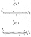
- proximale as is traditional, will refer to the end of the minimally invasive retraction device which is closest to the operator while the term “distal” will refer to the end of the device which is furthest from the operator.
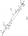
- Retractor 10 includes an open proximal end 12 and a distal end 14.
- retractor 10 includes a pair of retractor blades 8 having a plurality of instrument holes 6 disposed on each of retractor blades 8. Instrument holes 6 are configured and dimensioned to cooperate with different surgical instruments as will be discussed in detail hereinafter.
- a distal region 9 of retractor 10 includes an opening 7 ( FIG. 2 ), at least one slot or window 2, and a pair of arms 13 extending from distal end 14 to a flexible region or living hinge 4.
- Window 2 is sized and configured to receive instruments therethrough.
- Each retractor blade 8 is attached to living hinge 4 to define a substantially continuous elongate member.
- a pair of recesses 4a are formed between retractor blade 8 and arm 13 to define living hinge 4.
- a distal end 14 further includes at least one relief region R ( FIG. 2 ) defined by at least one slit 16 extending proximally from opening 7 ( FIG. 2 ).
- slit 16 may originate at window 2 and extend distally towards opening 7. It is contemplated that other arrangements of relief structures may be used to define relief region R and these may exist between opening 7 and window 2.
- Each slit 16 is a weakened portion of distal end 14. It may be a score in the material, a perforated region in the material, or another structural arrangement allowing relief region R to be radially displaced away from the centerline of retractor 10 in response to applied forces as will be discussed in detail hereinafter.
- distal end 14 has a generally convex outer surface that facilitates insertion of retractor 10 through layers of body tissue.
- Retractor blades 8 and arms 13 are generally arcuate structures that cooperate to define a substantially circular configuration for retractor 10. Each retractor blade 8 and each arm 13 have an arcuate configuration that is less than about 180° and are radially spaced apart to define a continuous slot 17 along a substantial portion of retractor 10. In addition, each retractor blade 8 and its corresponding arm 13 define a passage 18 that also extends substantially the entire length of retractor 10. Passage 18 is expandable, as will be discussed in detail hereinafter, for receiving a rod 3 ( FIG. 9 ) therein. Retractor blades 8 and arms 13 define a substantially circular ring shape, thereby providing sufficient stiffness (i.e. rigidity) such that retractor blades 8 and arms 13 resist bending from the counter forces of the retracted tissues.
- Opening 7 is located at distal end 14 of retractor 10 and is sized for receiving the shank of a threaded screw 40 ( FIG. 20 ) therethrough, but inhibiting passage of a head 42 of screw 40 so as to support screw 40 at distal end 14 of retractor 10.
- the interior surface of distal end 14 has a generally concave spherical geometry that is adapted to mate with head 42 of pedicle screw 40 that is best seen in FIG. 11 .
- Retractor 10 is formed from a suitable biocompatible material having the desired physical properties. That is, retractor 10 is formed of a biocompatible, sterilizable material in a suitable configuration and thickness so as to be sufficiently rigid to be held on the screw when desired during insertion and a surgical procedure and to provide retraction of tissue, and yet is sufficiently bendable to be spread apart to provide retraction and to be forcibly removed from the screw as necessary and appropriate. It is contemplated that retractor 10 may be formed from polymers such as polypropylene, polyethylene, or polycarbonate. Additionally, retractor 10 may be formed from silicone, polyetheretherketone (“PEEK”), or another suitable material.
- PEEK polyetheretherketone
- Retractor blade 8 is bendable away from the centerline of retractor 10 in response to applied forces, wherein retractor blade 8 bends at living hinge 4. Bending retractor blade 8 away from the centerline (i.e. radially outwards) creates a larger opening through retractor 10 and also acts to retract the surrounding tissue at the selected surgical site. Installation and use of retractor 10 in surgical procedures will be discussed in detail hereinafter.
- retractor 30 having an open proximal end 32 and a distal end 34.
- Retractor 30 includes a pair of retractor blades 36. Similar to retractor 10, distal end 34 has an interior surface with a generally concave spherical geometry that is adapted to mate with the head of a pedicle screw and has a generally convex outer surface that facilitates insertion of retractor 30 through layers of body tissue.
- retractor 30 includes an opening 7 ( FIG. 4 ) that is substantially identical to opening 7 of retractor 10.
- blades 36 have an arcuate configuration that is less than about 180° and are radially spaced apart to define a continuous slot 37 along a substantial portion of retractor 30. Additionally, retractor blades 36 defined a passage 35 through retractor 30. In this embodiment, retractor blades 36 are also flexible, but bend radially outwards from a centerline of retractor 30 near relief regions R ( FIG. 4 ). As in the previous embodiment, relief regions R are defined by slits 16 (shown as a pair of slits in FIG. 4 ) as previously discussed in connection with retractor 10.
- retraction of tissue with retractor blades 36 utilizes manual manipulation of retractor blades 36 by the physician rather than using a surgical instrument in cooperation with instrument holes 6 of retractor 10 ( FIG. 1 ).
- Removed of retractor 30 from the surgical site is accomplished by pulling retractor 30 proximally (i.e. away from the pedicle screw) and spreading or breaking distal end 34 along slits 16 such that relief regions R and retractor blades 36 separate from each other.
- the physician can readily remove the two parts from the surgical site.
- passage 36 is selectively expandable and contractible for receiving rod 3 therein.
- retractor 10 is illustrated in an assembled condition with a pedicle screw 40.
- Pedicle screw 40 extends through opening 7 ( FIG. 7 ) such that threads of pedicle screw 40 extend beyond distal end 14 ( FIG. 7 ) for insertion into a target site in a bone (e.g. a vertebral body).
- a bone e.g. a vertebral body
- the head of pedicle screw 42 FIG. 20
- rod receiving passage 44 of pedicle screw 40 FIG. 20
- pedicle screw 40 is pivotable about the longitudinal axis of retractor 10 allowing retractor 10 to be attached in a first angular orientation with respect to the vertebral body, but pivotable about pedicle screw 40 increasing the amount of tissue that may be retracted using retractor 10.
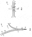
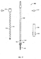
- FIGS. 8 and 9 Another embodiment of the presently disclosed retractor is illustrated in FIGS. 8 and 9 and shown generally as retractor 50.
- Retractor 50 is similar to retractor 10, but includes a plurality of living hinges 4 along with their corresponding recesses 4a.
- Retractor 50 is about 6 inches long and is readily adjusted to a desired length by removing excess material using scissors or a knife.
- retractor 50 has an inner diameter that is approximately 16mm and retractor blades are approximately 1mm thick.
- Each living hinge 4 is about 1-2 mm in heigth and each blade section 8a is about 5mm.
- Instrument holes 6 are on 1 cm centerlines.
- Slot 17 is typically at least 5.5mm, but will vary according to the size of the rod that will be inserted into the patient.
- each retractor blade 8' includes a plurality of blade sections 8a.
- Each blade section 8a is connected to an adjacent blade section 8a by a living hinge 4.
- the plurality of blade sections 8a and living hinges 4 define retractor blade 8'.
- each blade section 8' is substantially parallel to arm 13 to define slot 17 between retractor blades 8'.
- retractor blades 8' When retractor blades 8' are urged radially outward from their initial or rest position towards their retracted position, the size of passage 18 increases. This increase in the size and area of passage 18 improves access to the surgical target site (i.e. near where the retractor is inserted into tissue), thereby increasing visibility of the target site, access for instruments, and access for surgical implants. As shown in FIG. 9 , rod 3 is positioned in passage 18 after the surrounding tissue has been retracted using retractor 50. These advantages will be discussed in detail hereinafter. Additionally, the plurality of living hinges 4 greatly increases the adaptability of retractor 50 in comparision to retractor 10. While retractor blades 8 of retractor 10 ( FIG.
- retractor blades 8' will bend at the living hinge 4 that corresponds to the plane defined by the surface of the patient's body tissue.
- retractor 50 is usable in patient's having different tissue thicknesses between the vertebral body and the surface of their skin.
- each retractor blade 8' has a plurality of living hinges 4 and blade sections 8a, it is not required for each retractor blade 8' to bend at the same point along the length of retractor 50, thereby accommodating variances in the depth that retractor 50 is inserted.
- one retractor blade 8' may bend at its fourth living hinge 4, while the other retractor blade 8' may bend at its sixth living hinge 4, thereby accommodating variances in tissue thickness and orientation of retractor 50.
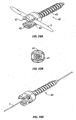
- retractor 60 is similar to retractor 10 ( FIG. 1 ) with the differences discussed in detail hereinafter.
- retractor 60 includes a distal end 14a with a distal region 9a.
- a distal region 9a includes arms 13a that extend circumferentially and do not form a portion of slot 17 as in the previous embodiment.
- a living hinge 4' is defined between window 2 and slot 17.
- distal region 9a includes slits 16a that are full cuts through the material of distal region 9a defining a plurality of relief regions R'.
- relief regions R' are more flexible such that retractor 60 may be separated from a pedicle screw (not shown) and subsequently affixed to the pedicle screw.
- This configuration permits a surgeon to remove and subcutaneously relocate retractor 60 to gain access to the vertebral disc space.
- positioning window 2 distally of slot 17 allows retractor 60 to expand in a medial-lateral orientation such that rod 3 ( FIG. 8 ) may be inserted through passage 18 into the target site.
- FIG. 11 illustrates an alternate embodiment of the presently disclosed retractor that is generally referenced as 70.
- Retractor 70 is substantially similar to the embodiment previously identified as retractor 60 ( FIG. 10 ). However, in this embodiment distal region 9b only includes one arm 13a, thereby increasing the lateral opening near distal end 14b and defining window 2a that is larger than previously disclosed window 2 ( FIG. 10 ). This embodiment provides increased access to the target site, thereby allowing larger implants or instruments to be positioned in the target site.
- FIG. 12 Another embodiment of the presently disclosed retractor is illustrated in FIG. 12 and referenced as retractor 80.
- Retractor 80 includes the same or substantially similar components as described hereinabove with respect to retractor 10 ( FIG. 1 ).
- retractors 80 includes only one retractor blade 8. This configuration allows greater variability in creating the retracted space as well as increasing access to the target site for using larger instruments or inserting larger devices than possible with retractor 10 ( FIG. 1 ).
- any of the previously disclosed retractors may be formed of a bendable resilient material such that when external spreading forces (i.e. from a Gelpi retractor or the physician's hands) are removed, the retractor blades will return towards their initial position (e.g., substantially parallel to the centerline). It is also contemplated that any of the previously disclosed retractors may be formed of a bendable non-resilient material such that when the external spreading forces are removed, the retractor blades resist returning to their initial position and remain in the retracted position.
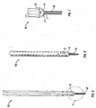
- a bone biopsy needle e.g. a Jamshidi needle
- Needle 100 includes a handle 102 disposed at a proximal end of needle 100, an elongate tubular member 104 extending distally from handle 102, and a stylet 106.
- Stylet 106 has a sharpened distal tip 108 that is adapted for penetrating tissue, including bone.
- tubular member 104 has a lumen extending from its proximal end to its distal end for receiving stylet 106 therethrough.
- Stylet 106 is releasably attached to handle 102 such that it may removed once the target site has been pierced by distal tip 108. After stylet 106 is removed, a guidewire 1 ( FIG. 27 ) may be inserted through tubular member 104 and secured or attached at the target site using known techniques.
- Scalpel 120 includes a housing 125 having a blade 126 disposed therein. Blade 126 has a sharpened distal end 124 for separating tissue. In addition, distal end 124 includes an opening 124a that cooperates with an opening 128 located at proximal end 122 and defines a channel through scalpel 120 for slidably receiving guidewire 1 ( FIG. 14A ) therethrough.
- FIG. 14A shows a dilator 300 configured and dimensioned to be received through a . retractor 10 with distal atraumatic blunt tip 302 protruding through opening 7 in retractor 10.
- Dilator 300 includes a longitudinal passage therethrough having a distal opening 304 for receiving guidewire 1 therethrough.
- dilator 300 may be used together with a cannula (not shown). Although less desirable, a series of dilators and cannulas can be used.
- Bone tap 140 includes an elongated body 142 having a proximal end 146 and a distal end 144.
- a distal end 144 includes a helical thread 145 for forming threads in a hole that is formed in a bony structure (i.e. a vertebral body).
- Proximal end 146 includes a tool engagement region 147 that is adapted for cooperating with a driving or rotating tool 178 ( FIG. 29 ) and forming the threads in the bony structure.
- Driving and rotating tools are well known in the art.
- proximal end 146 and distal end 144 cooperate to define a channel 148 extending through bone tap 140 such that bone tap 140 may be slid along guidewire 1.
- Bone tap 140 is available in a number of different sizes in a range of about 5.5mm to about 7.5mm. Alternatively, other bone taps may be used that match the size of the screw threads of the screw that will be implanted into bone.
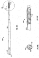
- Screw inserter 160 includes an anti-rotation sleeve 150 and a housing 170.
- Housing 170 includes a body 172 having a pair of handles 174 extending therefrom. Handles 174 facilitate positioning and/or rotating screw inserter 160.
- a tubular member 176 extends distally from body 172 and includes a plurality of holes 175.
- a shaft 166 ( FIG. 17 ) is disposed through a lumen of tubular member 176 and is rotatable therein.
- a tool engaging surface 163 is disposed at a proximal end 162 of shaft 166.
- a screw engaging structure 165 is disposed that is adapted and configured to releasbly engage a head 42 of pedicle screw 40.
- screw inserter includes a cross-member 164 and threads 173.
- screw engaging structure 165 is inserted into head 42 such that cross-member 163 occupies rod receiving recess 44 and threads 173 engage threaded portion 45 of pedicle screw 40. This arrangement releasably secures pedicle screw 40 to screw inserter 160.
- rotation of shaft 166 also causes rotation of pedicle screw 40 without causing rotation of housing 170.
- Anti-rotation sleeve 150 is located along an outer surface of tubular member 176 and includes protruding pins or buttons 152.
- buttons 152 are configured and adapted to releasably engage instrument holes 6 of retractor 10.
- retractor 10 is illustrated in cooperation with screw inserter 160
- screw inserter 160 is configured and adapted to cooperate with retractor 50, 60, and. 70.
- Buttons 152 of screw inserter 160 engage instrument holes 6 such that no rotational forces are transferred to the selected retractor while rotating and inserting pedicle screw 40 into a selected vertebral body. This arrangement permits insertion of pedicle screw 40 while minimizing displacement of the selected retractor from its desired location (i.e. target site).
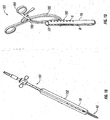
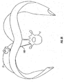
- Gelpi retractor 180 includes a pair of curvate arms 185 that are pivotably connected at pivot point 186.
- a pair of finger rings 184 are located at a proximal end of Gelpi retractor 180 that permit the physician to selectively move arms 185 towards and away from each other.
- a finger 182 is located at a distal end of each arm 185 and is configured to releasably engage an instrument hole 6 in retractor 10. As shown, finger rings 184 are laterally offset from arms 185. Thus, pivotable movement of arms 185 urge retractor blades 8 towards and away from each other in response to movement of finger rings 184.
- Gelpi retractor 180 is also configured and adapted to cooperate with retractor 50, 60, and 70.
- FIGS. 20-20B illustrate a cannulated minimally invasive pedicle screw 40.
- Pedicle screw 40 includes a helical thread 43 that is sized and configured for insertion into a threaded hole created by bone tap 140.
- a head 42 includes a tool engaging portion that is adapted to cooperate with screw insterter 160 as previously discussed.
- a rod receiving passage 44 is formed in head 42.
- head 42 includes a threaded portion 45 that is adapted to removably attach to the screw inserter 160 and receive a setscrew (not shown). The setscrew compresses against rod 3 in passage 44 and frictionally engages rod 3 to hold it in a desired position. Setscrews are well known in the art.
- a throughbore 47 extends between a proximal end and a distal end of pedicle screw 40 for receiving guidewire 1 therethrough ( FIG. 20B ).
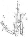
- Retractor extractor 200 includes handle portion 190, arms 210 and 220, and extractor bar 230.
- Handle portion 190 includes a handle grip 192 having openings 193, 194 disposed at one end thereof.
- Pin 196 extends through opening 194 and pivotably couples handle portion 190 to arms 210, 220 by extending through holes 212, 222 of arms 210, 220.
- a pin 195 extends through opening 193 and pivotably couples handle portion 190 to pivot bar 198 through hole 198a.
- hole 198b receives a pin 197.
- Pin 197 extends between arms 210, 220 and is slidably captured therebetween.
- pin 197 slides proximally and distally within a recess 224 of arm 220.
- Arm 210 has an identical recess that is not shown.
- pin 197 extends through an opening 236 of extractor bar 230.
- Retractor bar has a slot 230 that extends parallel to its longitudinal axis and slidably receives posts 202 therethrough.
- Posts 202 are attached to blade portions 216, 226 through openings 218, 228.
- posts 202 are adapted to releasably engage instrument holes 6 of the previously disclosed retractors ( FIG. 23 ).
- a blunt end 234 is located for bluntly engaging head 42 of pedicle screw 40 or a rod disposed therein.
- Pivoting handle grip 192 towards arms 210, 220 simultaneously moves extractor bar 230 distally (i.e. towards the screw) such that pins 202 on arms 210, 220 and distal blunt end 234 move apart relative to each other.
- This simultaneous relative movement between extractor bar 230 and pins 202 causes the retractor to separate from the pedicle screw at the relief regions without applying any appreciable downward forces on the implant or the patient.
- retractor 10 is assembled with pedicle screw 40 as shown in FIG. 24 .
- the assembled apparatus is inserted into an incision through the patient's skin S and muscle/fat tissue T such that pedicle screw 40 is subsequently threaded into a vertebral body V.
- retractor blades 8 are spread apart to retract skin S and tissue T to create a retracted area at the target site.
- retractor 50 may be assembled with pedicle screw 40 to retract tissue as shown in FIG. 25 .
- rod 3 is inserted in pasage 18 when passage 18 is in an expanded state (i.e. tissue has been retracted). Additionally, rod 3 is repositioned through passage 18 and subcutaneously such that is may be secured to fastening regions of pedicle screws in adjacent vertebral bodies.
- Biopsy needle 100 is inserted through skin S of the patient until its distal end contacts the selected point on vertebral body V.
- Biopsy needle 100 may be inserted in a known manner, such as percutaneously under fluoroscopic imaging, or under optical or magnetic image guidance (such as the STEALTH ® system available from Medtronic Sofamor Danek).
- a small puncture in the vertebral body V is made using sharpened distal tip 108 ( FIG. 13 ).
- guidewire 1 is inserted through biopsy needle 100 and affixed to vertebral body V.
- Guidewire 1 now is in position to direct further instruments and devices to the selected location on vertebral body V.
- guidewire 1 maybe insterted into vertebral body V without first using biopsy needle 100.
- the size of the working area may be increased at the physician's discretion.
- the physician may use scalpel 120 along guidewire 1 ( FIG. 28 ) to dissect additional tissue.
- a dilator 300 and optional retractor 10 may be inserted over the guidewire by inserting guidewire 1 through dilator opening 304 ( FIG. 14A ) with the dilator inserted through retractor 10.
- the dilator tip with retractor may be removed and placement of the guidewire may be inspected through the retractor. If the surgeon is satisfied with the placement of guidewire 1, then the procedure may continue through the retractor or the retractor may be removed and another inserted with a screw. If, on the other hand, the surgeon desires to change the guidewire location, another guidewire may be placed through the retractor, such as by inserting bone biopsy needle 100 through the retractor to a different placement in the bone and inserting a new guidewire at the new location. The former guidewire may then be removed. If desired, the physician may pre-drill a threaded bore in vertebral body V using bone tap 140 inserted along guidewire 1 to prepare the bore.
- an assemby including pedicle screw 40, retractor 10, and screw inserter 160 is slid along guidewire 1 to reach the target site.
- the physician rotates screw inserter 160 to drive pedicle screw 40 into vertebral body V ( FIG. 30 ).
- pedicle screw 40 is secured in vertebral body V
- screw inserter 160 is removed and retractor 10 remains in place secured by the screw which has been inserted into bone. This technique is also adapted for use with retractor 50.
- the finished result of the attached retractors is the same as shown in FIGS. 24 and 25 .
- Retractor blades 8 are spread apart to retract tissue in the working area. As previously discussed, retractor blades 8 may be spread apart using Gelpi retractor 180 ( FIG. 19 ) or by the physician manually grasping retractor blades 8 to urge them apart. After the desired retraction is achieved, rod 3 is inserted through passage 18 of retractor 10, 50 and is guided through window 2.
- a rod of sufficient length for a multiple level implant .construct may be inserted subcutaneously so that the rod is aligned with and inserted into a plurality of screw heads.
- This technique may be particularly useful in so-called 360 degree procedures where an interbody implant is inserted using an anterior approach and a screw-rod construct is inserted using a posterior approach.
- the surgeon may selectively make an incision between adjacent retractors. The latter approach permits a rod to be inserted through the incision to adjacent screws.
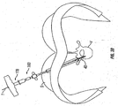
- retractor extractor 200 is positioned atop pedicle screw 40 such that distal end 234 of extractor bar 230 ( FIG. 23 ) rests flush against the set screw installed in head 42 of pedicle screw 40 or rests upon the rod installed in an alternate pedicle screw.
- the physician repositions retractor blades 8 towards arm blades 216, 226 ( FIG. 22 ) of retractor extractor 200 such that posts 202 enrage instrument holes 6.
- the physician pivots handle grip 192 towards arms 210, 220.
- This pivotable movement drives extractor bar 230 distally against head 42 while simultaneously pulling retractor blades 8 proximally such that relief regions R ( FIG. 1 ) separate from each other along slits 16.
- retractor 10, 50 is separated from pedicle screw 40 without imparting significant downward or rotational forces against the patient's body. Retractor 10, 50 may now be removed from the patient and this process may be repeated for each installed retractor.
- the physician first prepares the surgical site including positioning a guidewire as discussed hereinabove, optionally using scalpel 120 to prepare an incision, and inseting one of the previously disclosed retractors without a pedicle screw.
- the physician retracts the surrounding tissue as discussed hereinabove.
- the physician attaches pedicle screw 40 to the vertebral body V using screw inserter 160.
- the selected retractor is already in position prior to attachingpedicle screw 40 to vertebral body V.
- the physician assembles pedicle screw 40 and screw inserter 160.
- the screw insertion assembly is inserted into passage 18 of the retractor and pedicle screw 40 is rotated such that it bores into vertebral body V and head 42 seats on the interior surface of the distal region of the retractor and thus attaches the retractor to vertebral body V.
- the physician may use cannulated bone tap 140 to prepare the bore.
- each retractor is utilized, but not limited to, a method whereby an initial incision is made in the skin of approximately 10-15mm in length. Surgeon preference will dictate the need for one or more stages of dilators to aid in expanding the wound before introducing one or more retractors in combination with pedicle screws. Normal surgical techniques may be used to close the incision(s).
- the retractor may be manufactured from medical grade plastic or metal, thermoplastics, composites of plastic and metal, or biocompatible materials.
- a plastic part is made from, but not limited to, polypropylene and polyethylene.
- Plastic parts may be transparent or opaque and may have radio opaque markers for visibility during various imaging techniques.
- a metallic part utilizes such materials as, but not limited to, aluminum, stainless steel, and titanium.
- the parts may have a reflective or non-reflective coating to aid in increasing visibility in the wound and may have an artificial lighting feature.
- the disclosed retractors as with any surgical instrument and implant, must have the ability to be sterilized using known materials and techniques.
- Parts may be sterile packed by the manufacturer or sterilized on site by the user. Sterile packed parts may be individually packed or packed in any desirable quantity.
- a sterile package may contain one or a plurality of retractors in a sterile enclosure.
- such a sterile surgical kit may also include one or a plurality of bone biopsy needles ( FIG. 13 ), guide wires ( FIG. 20B ), sterile cannulated scalpels ( FIG. 14 ), or dilators ( FIG. 14A ).
- the retractors and methods described herein may find use in other orthopedic surgery applications, such as trauma surgery.
- the dilator, scalpel and retractors (or some of them) of the present disclosure may be used, with or without a bone screw.
Landscapes
- Health & Medical Sciences (AREA)
- Life Sciences & Earth Sciences (AREA)
- Surgery (AREA)
- Orthopedic Medicine & Surgery (AREA)
- Neurology (AREA)
- Veterinary Medicine (AREA)
- Engineering & Computer Science (AREA)
- Biomedical Technology (AREA)
- Heart & Thoracic Surgery (AREA)
- Animal Behavior & Ethology (AREA)
- General Health & Medical Sciences (AREA)
- Public Health (AREA)
- Molecular Biology (AREA)
- Nuclear Medicine, Radiotherapy & Molecular Imaging (AREA)
- Medical Informatics (AREA)
- Pathology (AREA)
- Radiology & Medical Imaging (AREA)
- Physics & Mathematics (AREA)
- Biophysics (AREA)
- Optics & Photonics (AREA)
- Oral & Maxillofacial Surgery (AREA)
- Dentistry (AREA)
- Hematology (AREA)
- Anesthesiology (AREA)
- Surgical Instruments (AREA)
- Materials For Medical Uses (AREA)
- Prostheses (AREA)
- Polysaccharides And Polysaccharide Derivatives (AREA)
- Medicines Containing Plant Substances (AREA)
- Devices For Conveying Motion By Means Of Endless Flexible Members (AREA)
- Gyroscopes (AREA)
- Golf Clubs (AREA)
Claims (16)
- Chirurgischer Retraktor (80), aufweisend:zumindest ein längliches Element (8);einen Kopplungsbereich (9), der an einem distalen Ende (14) des chirurgischen Retraktors angeordnet ist, wobei der Kopplungsbereich eine an einem distalen Ende des Kopplungsbereichs befindliche Öffnung (7) und zumindest einen Entlastungsbereich (R) umfasst, wobei der zumindest eine Entlastungsbereich konfiguriert und dimensioniert ist, um es dem Retraktor zu gestatten, sich von einem damit verbundenen Schraubenkopf bei Aufbringen einer vorgegebenen, ausreichenden Kraft zu trennen, um den Retraktor außer Eingriff mit der Schraube zu bringen; undeinem flexiblen Gelenk (4), das das längliche Element mit dem Kopplungsbereich koppelt, wobei das längliche Element von einer Mittellinie des Retraktors als Reaktion auf aufgebrachte Kräfte radial nach außen biegbar ist, um umgebendes Gewebe an einem Ort eines chirurgischen Eingriffs zurückzuziehen,wobei eine innere Oberfläche des distalen Endes des Retraktors eine im Allgemeinen konkav-sphärische Geometrie besitzt, die dazu ausgelegt ist, sich mit dem Kopf der darauf aufsitzenden Schraube zu verbinden, wenn sich der Schaft der Schraube durch die Öffnung erstreckt.
- Chirurgischer Retraktor nach Anspruch 1, wobei das zumindest eine längliche Element (8) zumindest eine Retraktorklinge (8) mit einer Vielzahl von darin angeordneten Instrumentenlöchern (6) bildet.
- Chirurgischer Retraktor nach Anspruch 1 oder 2, wobei das flexible Gelenkt ein Filmscharnier ist.
- Chirurgischer Retraktor nach Anspruch 3, wobei ein Paar Aussparungen (4a) zwischen dem länglichen Element (8) und dem Kopplungsbereich (13) gebildet ist, um das Filmscharnier (4) zu definieren.
- Chirurgischer Retraktor nach einem der vorstehenden Ansprüche, wobei es sich bei dem Entlastungsbereich (R) um eine strukturelle Anordnung handelt, die es dem Entlastungsbereich (R) ermöglicht, als Reaktion auf aufgebrachte Kräfte von einer Mittellinie des Retraktors radial weg verlagert zu werden.
- Chirurgischer Retraktor nach einem der vorstehenden Ansprüche, wobei der Entlastungsbereich (R) durch zumindest einen Schlitz (16) definiert ist, der sich proximal von der Öffnung (7) erstreckt.
- Chirurgischer Retraktor nach Anspruch 6, wobei der Retraktor durch proximales Ziehen des Retraktors und Spreizen des distalen Endes entlang des zumindest einen Schlitzes von der Schraube entfernbar ist.
- Chirurgischer Retraktor nach einem der vorstehenden Ansprüche, wobei Entlastungsbereiche durch Schlitze definiert sind, wobei die Trennung von der Schraube durch proximales Ziehen des Retraktors erreicht wird, um die Entlastungsbereiche entlang der Schlitze voneinander zu trennen.
- Chirurgischer Retraktor nach einem der vorstehenden Ansprüche, wobei sich die Öffnung an einem distalen Ende des Retraktors befindet und dimensioniert ist, um den Schaft einer Knochen-Pedikelschraube (40) durch sich aufzunehmen, jedoch den Durchtritt des Schraubenkopfs zu hemmen, um so die Schraube an dem distalen Ende des Retraktors zu lagern.
- Chirurgischer Retraktor nach einem der vorstehenden Ansprüche, wobei das distale Ende (14) eine im Allgemeinen konvexe Außenfläche besitzt, die das Einbringen des Retraktors (10) durch Körpergewebeschichten hindurch erleichtert.
- Chirurgischer Retraktor nach einem der vorstehenden Ansprüche, wobei das zumindest eine längliche Element zumindest eine Retraktorklinge bildet, die im Querschnitt über einer Länge des länglichen Elements aufgenommen eine im Allgemeinen bogenförmige Struktur ist.
- Chirurgischer Retraktor nach Anspruch 11, wobei die zumindest eine Retraktorklinge eine bogenförmige Ausgestaltung besitzt, die weniger als 180° beträgt.
- Chirurgischer Retraktor nach einem der vorstehenden Ansprüche, der einen Durchgang definiert, die sich im Wesentlichen über die gesamte Länge des Retraktors erstreckt.
- Chirurgischer Retraktor nach einem der vorstehenden Ansprüche, wobei das längliche Element eine Retraktorklinge bildet, die eine von einer längs gerichteten Mittellinie des Retraktors weggespreizte, gebogene Konfiguration und eine zur längs gerichteten Mittellinie im Wesentlichen parallele Ausgangskonfiguration besitzt.
- Chirurgischer Retraktor nach einem der vorstehenden Ansprüche, wobei der Retraktor in der Lage ist, einen Dilatator längsseitig durch sich hindurch aufzunehmen.
- Kit, aufweisend den chirurgischen Retraktor nach einem der vorstehenden Ansprüche und die Schraube, die bevorzugt eine Knochen-Pedikelschraube ist, wobei die Öffnung einen Durchmesser besitzt, der größer ist als ein Außendurchmesser des Schraubenschafts, und der Durchmesser der Öffnung kleiner ist als ein Außendurchmesser des Schraubenkopfes.
Applications Claiming Priority (2)
| Application Number | Priority Date | Filing Date | Title |
|---|---|---|---|
| US11/528,223 US7846093B2 (en) | 2005-09-26 | 2006-09-26 | Minimally invasive retractor and methods of use |
| EP07794511A EP2066223B1 (de) | 2006-09-26 | 2007-05-02 | Minimal invasiver retraktor |
Related Parent Applications (2)
| Application Number | Title | Priority Date | Filing Date |
|---|---|---|---|
| EP07794511.1 Division | 2007-05-02 | ||
| EP07794511A Division EP2066223B1 (de) | 2006-09-26 | 2007-05-02 | Minimal invasiver retraktor |
Publications (2)
| Publication Number | Publication Date |
|---|---|
| EP2384690A1 EP2384690A1 (de) | 2011-11-09 |
| EP2384690B1 true EP2384690B1 (de) | 2016-08-10 |
Family
ID=39230729
Family Applications (2)
| Application Number | Title | Priority Date | Filing Date |
|---|---|---|---|
| EP07794511A Active EP2066223B1 (de) | 2006-09-26 | 2007-05-02 | Minimal invasiver retraktor |
| EP11175322.4A Active EP2384690B1 (de) | 2006-09-26 | 2007-05-02 | Minimalinvasiver Retraktor |
Family Applications Before (1)
| Application Number | Title | Priority Date | Filing Date |
|---|---|---|---|
| EP07794511A Active EP2066223B1 (de) | 2006-09-26 | 2007-05-02 | Minimal invasiver retraktor |
Country Status (11)
| Country | Link |
|---|---|
| US (5) | US7846093B2 (de) |
| EP (2) | EP2066223B1 (de) |
| JP (2) | JP5249229B2 (de) |
| AT (1) | ATE536136T1 (de) |
| AU (1) | AU2007300727B2 (de) |
| CA (1) | CA2664731C (de) |
| DK (1) | DK2066223T3 (de) |
| ES (2) | ES2599835T3 (de) |
| PL (1) | PL2066223T3 (de) |
| PT (1) | PT2066223E (de) |
| WO (1) | WO2008039247A2 (de) |
Families Citing this family (111)
| Publication number | Priority date | Publication date | Assignee | Title |
|---|---|---|---|---|
| WO2005060837A2 (en) * | 2003-12-18 | 2005-07-07 | Depuy Spine, Inc. | Surgical retractor systems, illuminated cannulae, and methods of use |
| US20090187080A1 (en) * | 2004-08-15 | 2009-07-23 | Kevin Seex | Distraction and retraction assemblies |
| US7846093B2 (en) * | 2005-09-26 | 2010-12-07 | K2M, Inc. | Minimally invasive retractor and methods of use |
| US7918792B2 (en) | 2006-01-04 | 2011-04-05 | Depuy Spine, Inc. | Surgical retractor for use with minimally invasive spinal stabilization systems and methods of minimally invasive surgery |
| US7981031B2 (en) * | 2006-01-04 | 2011-07-19 | Depuy Spine, Inc. | Surgical access devices and methods of minimally invasive surgery |
| US7758501B2 (en) | 2006-01-04 | 2010-07-20 | Depuy Spine, Inc. | Surgical reactors and methods of minimally invasive surgery |
| US7955257B2 (en) * | 2006-01-05 | 2011-06-07 | Depuy Spine, Inc. | Non-rigid surgical retractor |
| CN101489497B (zh) | 2006-04-11 | 2011-01-26 | 新特斯有限责任公司 | 微创固定系统 |
| US8696560B2 (en) * | 2006-05-02 | 2014-04-15 | K2M, Inc. | Minimally open retraction device |
| US7892238B2 (en) | 2006-06-09 | 2011-02-22 | Zimmer Spine, Inc. | Methods and apparatus for access to and/or treatment of the spine |
| US8663292B2 (en) * | 2006-08-22 | 2014-03-04 | DePuy Synthes Products, LLC | Reduction sleeve |
| US8038699B2 (en) * | 2006-09-26 | 2011-10-18 | Ebi, Llc | Percutaneous instrument assembly |
| US8162952B2 (en) * | 2006-09-26 | 2012-04-24 | Ebi, Llc | Percutaneous instrument assembly |
| US7947045B2 (en) * | 2006-10-06 | 2011-05-24 | Zimmer Spine, Inc. | Spinal stabilization system with flexible guides |
| US20090012563A1 (en) * | 2006-10-11 | 2009-01-08 | Nas Medical Technologies, Inc. | Spinal fixation devices and methods |
| US8052720B2 (en) * | 2006-11-09 | 2011-11-08 | Zimmer Spine, Inc. | Minimally invasive pedicle screw access system and associated method |
| US8262662B2 (en) * | 2006-11-20 | 2012-09-11 | Depuy Spine, Inc. | Break-off screw extensions |
| US8062217B2 (en) | 2007-01-26 | 2011-11-22 | Theken Spine, Llc | Surgical retractor with removable blades and method of use |
| US8118737B2 (en) * | 2007-01-30 | 2012-02-21 | Mi4Spine, Llc | Retractor device for cervical spinal fusion |
| US8979749B2 (en) * | 2007-04-17 | 2015-03-17 | K2M, Inc. | Minimally open interbody access retraction device and surgical method |
| US8414588B2 (en) | 2007-10-04 | 2013-04-09 | Depuy Spine, Inc. | Methods and devices for minimally invasive spinal connection element delivery |
| US8251901B2 (en) * | 2007-10-08 | 2012-08-28 | Greatbatch Medical S.A. | Retractor for minimally invasive surgery |
| US9801667B2 (en) * | 2007-12-07 | 2017-10-31 | Nexus Spine, L.L.C. | Instruments, tools, and methods for presson pedicle screws |
| US20090222044A1 (en) * | 2008-02-28 | 2009-09-03 | K2M, Inc. | Minimally Invasive Retractor Screw and Methods of Use |
| US8747407B2 (en) | 2008-02-28 | 2014-06-10 | K2M, Inc. | Minimally invasive retractor and methods of use |
| US20090221879A1 (en) * | 2008-02-28 | 2009-09-03 | K2M, Inc. | Minimally Invasive Retractor Having Separable Blades |
| US8246538B2 (en) | 2008-02-28 | 2012-08-21 | K2M, Inc. | Minimally invasive retractor with separable blades and methods of use |
| US8097026B2 (en) * | 2008-02-28 | 2012-01-17 | K2M, Inc. | Minimally invasive retraction device having removable blades |
| US8932210B2 (en) * | 2008-02-28 | 2015-01-13 | K2M, Inc. | Minimally invasive retraction device having detachable blades |
| US20090275804A1 (en) * | 2008-04-30 | 2009-11-05 | Rudolf Bertagnoli | Hinged Retractor With Sheath |
| US20100036432A1 (en) * | 2008-08-05 | 2010-02-11 | Abbott Spine Inc. | Twist off reduction screw |
| WO2011040986A1 (en) * | 2009-09-30 | 2011-04-07 | Sherwin Hua | System and method for offset guidance in pedicle screw stabilization of spinal vertebrae |
| EP2341858B1 (de) | 2008-10-01 | 2014-02-12 | Sherwin Hua | System zur rückenwirbelstabilisierung mithilfe drahtgeführter pedikelschrauben |
| US8388659B1 (en) | 2008-10-17 | 2013-03-05 | Theken Spine, Llc | Spondylolisthesis screw and instrument for implantation |
| US8439923B2 (en) * | 2008-10-17 | 2013-05-14 | Omni Surgical LLC | Poly-axial pedicle screw assembly |
| US8137356B2 (en) * | 2008-12-29 | 2012-03-20 | Zimmer Spine, Inc. | Flexible guide for insertion of a vertebral stabilization system |
| US8727972B2 (en) * | 2009-02-03 | 2014-05-20 | Warsaw Orthopedic, Inc. | Low profile bone screw extender and its application in minimum invasive spinal surgeries |
| JP5658237B2 (ja) | 2009-05-20 | 2015-01-21 | ジンテス ゲゼルシャフト ミット ベシュレンクテル ハフツング | 患者装着式開創器 |
| US20100305407A1 (en) * | 2009-06-02 | 2010-12-02 | Farley Daniel K | Malleable Port Retractor |
| US8152720B2 (en) | 2009-08-05 | 2012-04-10 | Thomas Stuart Loftus | Retracto component system and method of using same |
| US20120232350A1 (en) * | 2009-08-31 | 2012-09-13 | Kevin Seex | Retractor blade including a flexible member for anchorage engagement |
| EP2485667A1 (de) * | 2009-10-05 | 2012-08-15 | CoLigne AG | Wirbelsäulenfixationssystem und schraubendreherinstrument zur verwendung damit |
| US9655658B2 (en) * | 2009-10-14 | 2017-05-23 | Ebi, Llc | Deformable device for minimally invasive fixation |
| US8236032B2 (en) * | 2009-10-20 | 2012-08-07 | Depuy Spine, Inc. | Spinal implant with a flexible extension element |
| CN102821673B (zh) * | 2009-11-10 | 2016-06-08 | 纽瓦西弗公司 | 牵开器系统 |
| FR2954689B1 (fr) | 2009-12-28 | 2012-12-21 | Sterispine | Dispositif et methode pour la chirurgie rachidienne. |
| US8636655B1 (en) | 2010-01-19 | 2014-01-28 | Ronald Childs | Tissue retraction system and related methods |
| SE534703C2 (sv) * | 2010-02-12 | 2011-11-22 | Elos Medical Ab | Sårhake med fastsättningspinne som har plygonisk tvärsnittsarea |
| MX2012011091A (es) | 2010-03-26 | 2013-03-07 | Echostar Technologies Llc | Receptor de television de entrada multiple. |
| EP2552333A4 (de) | 2010-03-30 | 2014-11-26 | Sherwin Hua | Systeme und verfahren zur rückenwirbelstabilisierung mithilfe von pedikelschrauben |
| US8535318B2 (en) * | 2010-04-23 | 2013-09-17 | DePuy Synthes Products, LLC | Minimally invasive instrument set, devices and related methods |
| US20120016424A1 (en) * | 2010-07-19 | 2012-01-19 | Warsaw Orthopedic, Inc. | Extensions for spinal anchors |
| JP6045497B2 (ja) | 2010-10-08 | 2016-12-14 | ケー2エム, インコーポレイテッド | 側方アクセスシステムおよび使用方法 |
| GB2528416B (en) * | 2010-11-10 | 2016-05-18 | Nuvasive Inc | Apparatus for performing spinal surgery |
| US8956284B2 (en) | 2011-01-20 | 2015-02-17 | K2M, Inc. | Minimally invasive retractor and posted screw |
| US9186184B2 (en) * | 2011-02-14 | 2015-11-17 | Pioneer Surgical Technology, Inc. | Spinal fixation system and method |
| US9307972B2 (en) | 2011-05-10 | 2016-04-12 | Nuvasive, Inc. | Method and apparatus for performing spinal fusion surgery |
| US8617218B2 (en) | 2011-05-13 | 2013-12-31 | Warsaw Orthoepdic, Inc. | Bone anchor extenders |
| US9314274B2 (en) | 2011-05-27 | 2016-04-19 | DePuy Synthes Products, Inc. | Minimally invasive spinal fixation system including vertebral alignment features |
| US20130053896A1 (en) * | 2011-08-29 | 2013-02-28 | Jean-Marc VOYADZIS | Adaptable systems, methods, and devices for percutaneously implanting a spinal screw |
| US9414862B2 (en) | 2011-10-24 | 2016-08-16 | Warsaw Orthopedic, Inc. | Bone fastener for a spinal surgical system |
| US8668715B2 (en) * | 2011-11-14 | 2014-03-11 | Custom Spine, Inc. | Cervical spine retractor |
| US9125703B2 (en) | 2012-01-16 | 2015-09-08 | K2M, Inc. | Rod reducer, compressor, distractor system |
| US9220539B2 (en) | 2012-03-19 | 2015-12-29 | Warsaw Orthopedic, Inc. | Spinal implant system and method |
| US9078709B2 (en) | 2012-03-19 | 2015-07-14 | Warsaw Orthopedic, Inc. | Spinal implant system and method |
| US8439924B1 (en) | 2012-04-02 | 2013-05-14 | Warsaw Orthopedic, Inc. | Spinal implant system and method |
| US9295488B2 (en) | 2012-08-09 | 2016-03-29 | Wilson T. Asfora | Joint fusion |
| US9451998B2 (en) | 2012-08-17 | 2016-09-27 | Warsaw Orthopedic, Inc. | Spinal implant system and method |
| US9066758B2 (en) | 2012-08-17 | 2015-06-30 | Warsaw Orthopedic, Inc. | Spinal implant system and method |
| RO130040A2 (ro) * | 2012-10-31 | 2015-02-27 | Saba Nahedd | Procedeu privind ancorarea istmului uterin prin bandeleta la teaca drepţilor abdominali |
| FR3001628B1 (fr) | 2013-02-05 | 2017-11-24 | Safe Orthopaedics | Ensemble d'implantation comprenant un instrument d'entrainement pre-monte sur un implant osseux. |
| US9510875B2 (en) * | 2013-03-14 | 2016-12-06 | Stryker European Holdings I, Llc | Systems and methods for percutaneous spinal fusion |
| CN114983546A (zh) | 2013-05-13 | 2022-09-02 | 尼奥医疗公司 | 矫形植入套件 |
| JP6290002B2 (ja) * | 2013-06-07 | 2018-03-07 | 賢 石井 | 脊椎固定用装置 |
| US9402659B2 (en) | 2013-08-06 | 2016-08-02 | Warsaw Orthopedic, Inc. | Spinal implant system |
| US9402661B2 (en) | 2013-09-23 | 2016-08-02 | Stryker European Holdings I, LCC | Lumbar-sacral screw insertion and manipulation |
| AU2014332172B2 (en) * | 2013-10-07 | 2019-05-30 | K2M, Inc. | Rod reducer |
| CA2874390C (en) | 2013-12-13 | 2018-03-06 | Stryker European Holdings I, Llc | Tissue retraction and vertebral displacement devices, systems, and methods for posterior spinal fusion |
| WO2015138317A1 (en) | 2014-03-10 | 2015-09-17 | Stryker Corporation | Limb positioning system |
| US9642654B2 (en) * | 2014-06-16 | 2017-05-09 | Alphatec Spine, Inc. | Single action locking pedicle screwdriver |
| US10258228B2 (en) | 2014-08-08 | 2019-04-16 | K2M, Inc. | Retraction devices, systems, and methods for minimally invasive spinal surgery |
| GB2598671B (en) | 2014-08-13 | 2022-07-13 | Nuvasive Inc | Minimally disruptive retractor and associated methods for spinal surgery |
| KR101601019B1 (ko) * | 2014-08-27 | 2016-03-21 | 장상훈 | 경추용 리트랙터 |
| WO2016041001A1 (en) * | 2014-09-15 | 2016-03-24 | Cryptych Pty Ltd | A fiducial marker |
| EP3047811B1 (de) | 2015-01-15 | 2022-05-18 | K2M, Inc. | Stabreduzierer |
| US9848928B2 (en) * | 2015-02-20 | 2017-12-26 | Warsaw Orthopedic, Inc. | Spinal implant system and methods of use |
| US9951904B2 (en) | 2015-03-24 | 2018-04-24 | Stryker Corporation | Rotatable seat clamps for rail clamp |
| WO2016175885A1 (en) | 2015-04-30 | 2016-11-03 | K2M, Inc. | Rod reducer |
| US9968394B2 (en) * | 2015-06-01 | 2018-05-15 | Alphatec Spine, Inc. | Instrument for removing tabs from a reduction screw |
| US10499894B2 (en) | 2015-08-12 | 2019-12-10 | K2M, Inc. | Orthopedic surgical system including surgical access systems, distraction systems, and methods of using same |
| US10149674B2 (en) | 2015-08-12 | 2018-12-11 | K2M, Inc. | Orthopedic surgical system including surgical access systems, distraction systems, and methods of using same |
| WO2017027694A1 (en) | 2015-08-13 | 2017-02-16 | K2M, Inc. | Extended tab systems for reducing spinal rods |
| US10278687B2 (en) * | 2015-08-18 | 2019-05-07 | Globus Medical, Inc. | Devices and systems for surgical retraction |
| US20180289363A1 (en) * | 2015-10-06 | 2018-10-11 | K2M, Inc. | Surgical access system, devices thereof, and methods of using the same |
| US20190336182A1 (en) * | 2015-10-27 | 2019-11-07 | Ctl Medical Corporation | Modular rod reduction tower and related methods |
| US10524843B2 (en) | 2016-05-06 | 2020-01-07 | K2M, Inc. | Rotation shaft for a rod reducer |
| US10405842B2 (en) | 2016-09-26 | 2019-09-10 | K2M, Inc. | Retraction system and method of use |
| EP3515340A4 (de) * | 2016-09-26 | 2020-05-27 | Dr. Bryan Barnes PC. | Vorrichtung, system und verfahren zur wirbelsäulenstabilisierung |
| US10052140B2 (en) * | 2016-10-05 | 2018-08-21 | Stryker European Holdings I, Llc | Apparatus and method for fenestrated screw augmentation |
| US10603078B2 (en) | 2016-10-26 | 2020-03-31 | Warsaw Orthopedic, Inc. | Surgical instrument and method |
| US10779866B2 (en) | 2016-12-29 | 2020-09-22 | K2M, Inc. | Rod reducer assembly |
| US10485590B2 (en) | 2017-01-18 | 2019-11-26 | K2M, Inc. | Rod reducing device |
| US10973558B2 (en) | 2017-06-12 | 2021-04-13 | K2M, Inc. | Screw insertion instrument and methods of use |
| US11298119B2 (en) | 2018-06-19 | 2022-04-12 | K2M, Inc. | Spinal retractor and method of use therefor |
| US11399819B2 (en) * | 2018-07-11 | 2022-08-02 | Lsi Solutions, Inc. | Percutaneous sub-xiphoid lifting device and methods thereof |
| US11160580B2 (en) | 2019-04-24 | 2021-11-02 | Spine23 Inc. | Systems and methods for pedicle screw stabilization of spinal vertebrae |
| USD941470S1 (en) | 2019-11-07 | 2022-01-18 | K2M, Inc. | Surgical blade |
| EP3818952A1 (de) | 2019-11-07 | 2021-05-12 | K2M, Inc. | Inzisionswerkzeuge und verfahren zu ihrer verwendung |
| EP4065016A1 (de) * | 2019-11-27 | 2022-10-05 | Spine23 Inc. | Systeme, vorrichtungen und verfahren zum behandeln einer lateralen krümmung einer wirbelsäule |
| WO2022241140A1 (en) | 2021-05-12 | 2022-11-17 | Spine23 Inc. | Systems and methods for pedicle screw stabilization of spinal vertebrae |
| US11737795B1 (en) * | 2022-02-28 | 2023-08-29 | Globus Medical, Inc. | System and methods for rod insertion using a screw tower |
Family Cites Families (48)
| Publication number | Priority date | Publication date | Assignee | Title |
|---|---|---|---|---|
| US3129706A (en) | 1962-11-13 | 1964-04-21 | Jr Walker Reynolds | Surgical retractor |
| US5454365A (en) | 1990-11-05 | 1995-10-03 | Bonutti; Peter M. | Mechanically expandable arthroscopic retractors |
| US5242443A (en) | 1991-08-15 | 1993-09-07 | Smith & Nephew Dyonics, Inc. | Percutaneous fixation of vertebrae |
| US5582577A (en) | 1995-02-13 | 1996-12-10 | Vance Products Incorporated | Surgical retractor including central elastic member |
| JP2895789B2 (ja) | 1995-12-14 | 1999-05-24 | 株式会社椿本チエイン | 油圧式テンショナ |
| US6048309A (en) * | 1996-03-04 | 2000-04-11 | Heartport, Inc. | Soft tissue retractor and delivery device therefor |
| US5792044A (en) | 1996-03-22 | 1998-08-11 | Danek Medical, Inc. | Devices and methods for percutaneous surgery |
| CA2280757A1 (en) | 1997-02-13 | 1998-08-20 | William Pintauro | Method and apparatus for minimally invasive pelvic surgery |
| JPH1176247A (ja) * | 1997-07-11 | 1999-03-23 | Olympus Optical Co Ltd | 外科手術システム |
| US5944658A (en) | 1997-09-23 | 1999-08-31 | Koros; Tibor B. | Lumbar spinal fusion retractor and distractor system |
| US6206826B1 (en) | 1997-12-18 | 2001-03-27 | Sdgi Holdings, Inc. | Devices and methods for percutaneous surgery |
| US6187000B1 (en) | 1998-08-20 | 2001-02-13 | Endius Incorporated | Cannula for receiving surgical instruments |
| US6530926B1 (en) | 2000-08-01 | 2003-03-11 | Endius Incorporated | Method of securing vertebrae |
| US6055456A (en) | 1999-04-29 | 2000-04-25 | Medtronic, Inc. | Single and multi-polar implantable lead for sacral nerve electrical stimulation |
| US6200322B1 (en) | 1999-08-13 | 2001-03-13 | Sdgi Holdings, Inc. | Minimal exposure posterior spinal interbody instrumentation and technique |
| US7662161B2 (en) * | 1999-09-13 | 2010-02-16 | Rex Medical, L.P | Vascular hole closure device |
| US6530929B1 (en) | 1999-10-20 | 2003-03-11 | Sdgi Holdings, Inc. | Instruments for stabilization of bony structures |
| US6270501B1 (en) * | 1999-11-08 | 2001-08-07 | The Regents Of The University Of Michigan | Surgical method and apparatus and cannulated scalpel for use therein |
| US6743206B1 (en) | 2000-03-07 | 2004-06-01 | Syntheon, Llc | Endoscopic needle |
| US7056321B2 (en) | 2000-08-01 | 2006-06-06 | Endius, Incorporated | Method of securing vertebrae |
| US7166107B2 (en) | 2000-09-11 | 2007-01-23 | D. Greg Anderson | Percutaneous technique and implant for expanding the spinal canal |
| US6929606B2 (en) | 2001-01-29 | 2005-08-16 | Depuy Spine, Inc. | Retractor and method for spinal pedicle screw placement |
| US6616605B2 (en) | 2001-02-15 | 2003-09-09 | Genesee Biomedical, Inc. | Quadretractor and method of use |
| US6802844B2 (en) | 2001-03-26 | 2004-10-12 | Nuvasive, Inc | Spinal alignment apparatus and methods |
| US7144393B2 (en) | 2001-05-15 | 2006-12-05 | Dipoto Gene P | Structure for receiving surgical instruments |
| JP3832721B2 (ja) * | 2001-05-21 | 2006-10-11 | ソニー株式会社 | プリントシステム及びプリント方法並びに記録媒体 |
| US6659945B2 (en) | 2001-06-29 | 2003-12-09 | Depuy Orthopaedics, Inc. | Self retaining retractor ring |
| US6884240B1 (en) * | 2001-12-07 | 2005-04-26 | Ronald Dykes | Protection system for surgical instruments |
| US7261688B2 (en) | 2002-04-05 | 2007-08-28 | Warsaw Orthopedic, Inc. | Devices and methods for percutaneous tissue retraction and surgery |
| US7582058B1 (en) * | 2002-06-26 | 2009-09-01 | Nuvasive, Inc. | Surgical access system and related methods |
| US6849064B2 (en) | 2002-10-25 | 2005-02-01 | James S. Hamada | Minimal access lumbar diskectomy instrumentation and method |
| US7935054B2 (en) * | 2002-10-25 | 2011-05-03 | K2M, Inc. | Minimal access lumbar diskectomy instrumentation and method |
| US20040172022A1 (en) * | 2002-10-30 | 2004-09-02 | Landry Michael E. | Bone fastener assembly for a spinal stabilization system |
| US7473267B2 (en) | 2003-04-25 | 2009-01-06 | Warsaw Orthopedic, Inc. | System and method for minimally invasive posterior fixation |
| US6796422B1 (en) | 2003-08-07 | 2004-09-28 | Bae Her Industrial Corp. | Eyeglass case |
| US7481766B2 (en) * | 2003-08-14 | 2009-01-27 | Synthes (U.S.A.) | Multiple-blade retractor |
| US7955355B2 (en) | 2003-09-24 | 2011-06-07 | Stryker Spine | Methods and devices for improving percutaneous access in minimally invasive surgeries |
| US20050065516A1 (en) | 2003-09-24 | 2005-03-24 | Tae-Ahn Jahng | Method and apparatus for flexible fixation of a spine |
| US8002798B2 (en) | 2003-09-24 | 2011-08-23 | Stryker Spine | System and method for spinal implant placement |
| US7179261B2 (en) | 2003-12-16 | 2007-02-20 | Depuy Spine, Inc. | Percutaneous access devices and bone anchor assemblies |
| US7625379B2 (en) | 2004-01-26 | 2009-12-01 | Warsaw Orthopedic, Inc. | Methods and instrumentation for inserting intervertebral grafts and devices |
| US7160300B2 (en) | 2004-02-27 | 2007-01-09 | Jackson Roger P | Orthopedic implant rod reduction tool set and method |
| US7666189B2 (en) * | 2004-09-29 | 2010-02-23 | Synthes Usa, Llc | Less invasive surgical system and methods |
| WO2006091863A2 (en) * | 2005-02-23 | 2006-08-31 | Pioneer Laboratories, Inc. | Minimally invasive surgical system |
| US20060229636A1 (en) * | 2005-03-04 | 2006-10-12 | Woodburn William N Sr | Expandable access device with mobility member |
| US7491208B2 (en) | 2005-04-28 | 2009-02-17 | Warsaw Orthopedic, Inc. | Instrument and method for guiding surgical implants and instruments during surgery |
| US7846093B2 (en) | 2005-09-26 | 2010-12-07 | K2M, Inc. | Minimally invasive retractor and methods of use |
| US8439923B2 (en) * | 2008-10-17 | 2013-05-14 | Omni Surgical LLC | Poly-axial pedicle screw assembly |
-
2006
- 2006-09-26 US US11/528,223 patent/US7846093B2/en active Active
-
2007
- 2007-05-02 DK DK07794511.1T patent/DK2066223T3/da active
- 2007-05-02 JP JP2009529168A patent/JP5249229B2/ja active Active
- 2007-05-02 AT AT07794511T patent/ATE536136T1/de active
- 2007-05-02 ES ES11175322.4T patent/ES2599835T3/es active Active
- 2007-05-02 PT PT07794511T patent/PT2066223E/pt unknown
- 2007-05-02 PL PL07794511T patent/PL2066223T3/pl unknown
- 2007-05-02 ES ES07794511T patent/ES2378576T3/es active Active
- 2007-05-02 EP EP07794511A patent/EP2066223B1/de active Active
- 2007-05-02 AU AU2007300727A patent/AU2007300727B2/en active Active
- 2007-05-02 WO PCT/US2007/010716 patent/WO2008039247A2/en active Application Filing
- 2007-05-02 CA CA2664731A patent/CA2664731C/en not_active Expired - Fee Related
- 2007-05-02 EP EP11175322.4A patent/EP2384690B1/de active Active
-
2010
- 2010-11-08 US US12/941,143 patent/US8298138B2/en active Active
-
2012
- 2012-10-10 US US13/648,409 patent/US8734338B2/en active Active
- 2012-12-28 JP JP2012287725A patent/JP5486076B2/ja not_active Expired - Fee Related
-
2014
- 2014-05-01 US US14/267,363 patent/US9161779B2/en active Active
-
2015
- 2015-10-20 US US14/887,840 patent/US9510858B2/en active Active
Also Published As
| Publication number | Publication date |
|---|---|
| ES2599835T3 (es) | 2017-02-03 |
| US9161779B2 (en) | 2015-10-20 |
| US20110054259A1 (en) | 2011-03-03 |
| US8298138B2 (en) | 2012-10-30 |
| US20070106123A1 (en) | 2007-05-10 |
| WO2008039247A3 (en) | 2008-06-05 |
| PT2066223E (pt) | 2012-01-03 |
| US20140243605A1 (en) | 2014-08-28 |
| US8734338B2 (en) | 2014-05-27 |
| EP2384690A1 (de) | 2011-11-09 |
| ES2378576T3 (es) | 2012-04-16 |
| DK2066223T3 (da) | 2012-02-06 |
| EP2066223A2 (de) | 2009-06-10 |
| CA2664731A1 (en) | 2008-04-03 |
| ATE536136T1 (de) | 2011-12-15 |
| US9510858B2 (en) | 2016-12-06 |
| EP2066223A4 (de) | 2010-03-17 |
| EP2066223B1 (de) | 2011-12-07 |
| AU2007300727B2 (en) | 2013-08-29 |
| US20160038182A1 (en) | 2016-02-11 |
| CA2664731C (en) | 2015-07-07 |
| JP5249229B2 (ja) | 2013-07-31 |
| AU2007300727A1 (en) | 2008-04-03 |
| WO2008039247A2 (en) | 2008-04-03 |
| JP5486076B2 (ja) | 2014-05-07 |
| PL2066223T3 (pl) | 2012-04-30 |
| US20130041228A1 (en) | 2013-02-14 |
| JP2013078644A (ja) | 2013-05-02 |
| US7846093B2 (en) | 2010-12-07 |
| JP2010504771A (ja) | 2010-02-18 |
Similar Documents
| Publication | Publication Date | Title |
|---|---|---|
| US9510858B2 (en) | Minimally invasive retractor and methods of use | |
| US11812940B2 (en) | Minimally open interbody access retraction device and surgical method | |
| US8376940B2 (en) | Minimally invasive retractor with separable blades and methods of use | |
| US8870878B2 (en) | Minimally invasive retractor and methods of use | |
| US20140243602A1 (en) | Minimally invasive retractor screw and methods of use | |
| US8097026B2 (en) | Minimally invasive retraction device having removable blades | |
| US8932210B2 (en) | Minimally invasive retraction device having detachable blades | |
| US20090221879A1 (en) | Minimally Invasive Retractor Having Separable Blades | |
| US10925592B2 (en) | Tissue dilation system and methods of use | |
| US8956284B2 (en) | Minimally invasive retractor and posted screw | |
| AU2013263733B2 (en) | Minimally invasive retractor and methods of use |
Legal Events
| Date | Code | Title | Description |
|---|---|---|---|
| AC | Divisional application: reference to earlier application |
Ref document number: 2066223 Country of ref document: EP Kind code of ref document: P |
|
| AK | Designated contracting states |
Kind code of ref document: A1 Designated state(s): AT BE BG CH CY CZ DE DK EE ES FI FR GB GR HU IE IS IT LI LT LU LV MC MT NL PL PT RO SE SI SK TR |
|
| PUAI | Public reference made under article 153(3) epc to a published international application that has entered the european phase |
Free format text: ORIGINAL CODE: 0009012 |
|
| 17P | Request for examination filed |
Effective date: 20120508 |
|
| 17Q | First examination report despatched |
Effective date: 20130410 |
|
| REG | Reference to a national code |
Ref country code: DE Ref legal event code: R079 Ref document number: 602007047444 Country of ref document: DE Free format text: PREVIOUS MAIN CLASS: A61B0001320000 Ipc: A61B0017020000 |
|
| RIC1 | Information provided on ipc code assigned before grant |
Ipc: A61B 17/02 20060101AFI20140902BHEP Ipc: A61B 1/32 20060101ALI20140902BHEP |
|
| GRAP | Despatch of communication of intention to grant a patent |
Free format text: ORIGINAL CODE: EPIDOSNIGR1 |
|
| INTG | Intention to grant announced |
Effective date: 20141204 |
|
| INTG | Intention to grant announced |
Effective date: 20141211 |
|
| INTG | Intention to grant announced |
Effective date: 20160219 |
|
| GRAS | Grant fee paid |
Free format text: ORIGINAL CODE: EPIDOSNIGR3 |
|
| GRAA | (expected) grant |
Free format text: ORIGINAL CODE: 0009210 |
|
| AC | Divisional application: reference to earlier application |
Ref document number: 2066223 Country of ref document: EP Kind code of ref document: P |
|
| AK | Designated contracting states |
Kind code of ref document: B1 Designated state(s): AT BE BG CH CY CZ DE DK EE ES FI FR GB GR HU IE IS IT LI LT LU LV MC MT NL PL PT RO SE SI SK TR |
|
| REG | Reference to a national code |
Ref country code: GB Ref legal event code: FG4D |
|
| REG | Reference to a national code |
Ref country code: CH Ref legal event code: EP Ref country code: AT Ref legal event code: REF Ref document number: 818211 Country of ref document: AT Kind code of ref document: T Effective date: 20160815 |
|
| REG | Reference to a national code |
Ref country code: IE Ref legal event code: FG4D |
|
| REG | Reference to a national code |
Ref country code: DE Ref legal event code: R096 Ref document number: 602007047444 Country of ref document: DE |
|
| REG | Reference to a national code |
Ref country code: LT Ref legal event code: MG4D |
|
| REG | Reference to a national code |
Ref country code: NL Ref legal event code: MP Effective date: 20160810 |
|
| REG | Reference to a national code |
Ref country code: AT Ref legal event code: MK05 Ref document number: 818211 Country of ref document: AT Kind code of ref document: T Effective date: 20160810 |
|
| PG25 | Lapsed in a contracting state [announced via postgrant information from national office to epo] |
Ref country code: FI Free format text: LAPSE BECAUSE OF FAILURE TO SUBMIT A TRANSLATION OF THE DESCRIPTION OR TO PAY THE FEE WITHIN THE PRESCRIBED TIME-LIMIT Effective date: 20160810 Ref country code: IS Free format text: LAPSE BECAUSE OF FAILURE TO SUBMIT A TRANSLATION OF THE DESCRIPTION OR TO PAY THE FEE WITHIN THE PRESCRIBED TIME-LIMIT Effective date: 20161210 Ref country code: LT Free format text: LAPSE BECAUSE OF FAILURE TO SUBMIT A TRANSLATION OF THE DESCRIPTION OR TO PAY THE FEE WITHIN THE PRESCRIBED TIME-LIMIT Effective date: 20160810 Ref country code: NL Free format text: LAPSE BECAUSE OF FAILURE TO SUBMIT A TRANSLATION OF THE DESCRIPTION OR TO PAY THE FEE WITHIN THE PRESCRIBED TIME-LIMIT Effective date: 20160810 |
|
| REG | Reference to a national code |
Ref country code: ES Ref legal event code: FG2A Ref document number: 2599835 Country of ref document: ES Kind code of ref document: T3 Effective date: 20170203 |
|
| PG25 | Lapsed in a contracting state [announced via postgrant information from national office to epo] |
Ref country code: LV Free format text: LAPSE BECAUSE OF FAILURE TO SUBMIT A TRANSLATION OF THE DESCRIPTION OR TO PAY THE FEE WITHIN THE PRESCRIBED TIME-LIMIT Effective date: 20160810 Ref country code: PT Free format text: LAPSE BECAUSE OF FAILURE TO SUBMIT A TRANSLATION OF THE DESCRIPTION OR TO PAY THE FEE WITHIN THE PRESCRIBED TIME-LIMIT Effective date: 20161212 Ref country code: SE Free format text: LAPSE BECAUSE OF FAILURE TO SUBMIT A TRANSLATION OF THE DESCRIPTION OR TO PAY THE FEE WITHIN THE PRESCRIBED TIME-LIMIT Effective date: 20160810 Ref country code: AT Free format text: LAPSE BECAUSE OF FAILURE TO SUBMIT A TRANSLATION OF THE DESCRIPTION OR TO PAY THE FEE WITHIN THE PRESCRIBED TIME-LIMIT Effective date: 20160810 Ref country code: GR Free format text: LAPSE BECAUSE OF FAILURE TO SUBMIT A TRANSLATION OF THE DESCRIPTION OR TO PAY THE FEE WITHIN THE PRESCRIBED TIME-LIMIT Effective date: 20161111 Ref country code: PL Free format text: LAPSE BECAUSE OF FAILURE TO SUBMIT A TRANSLATION OF THE DESCRIPTION OR TO PAY THE FEE WITHIN THE PRESCRIBED TIME-LIMIT Effective date: 20160810 |
|
| REG | Reference to a national code |
Ref country code: FR Ref legal event code: PLFP Year of fee payment: 11 |
|
| PG25 | Lapsed in a contracting state [announced via postgrant information from national office to epo] |
Ref country code: EE Free format text: LAPSE BECAUSE OF FAILURE TO SUBMIT A TRANSLATION OF THE DESCRIPTION OR TO PAY THE FEE WITHIN THE PRESCRIBED TIME-LIMIT Effective date: 20160810 Ref country code: RO Free format text: LAPSE BECAUSE OF FAILURE TO SUBMIT A TRANSLATION OF THE DESCRIPTION OR TO PAY THE FEE WITHIN THE PRESCRIBED TIME-LIMIT Effective date: 20160810 |
|
| REG | Reference to a national code |
Ref country code: DE Ref legal event code: R097 Ref document number: 602007047444 Country of ref document: DE |
|
| PG25 | Lapsed in a contracting state [announced via postgrant information from national office to epo] |
Ref country code: BE Free format text: LAPSE BECAUSE OF FAILURE TO SUBMIT A TRANSLATION OF THE DESCRIPTION OR TO PAY THE FEE WITHIN THE PRESCRIBED TIME-LIMIT Effective date: 20160810 Ref country code: DK Free format text: LAPSE BECAUSE OF FAILURE TO SUBMIT A TRANSLATION OF THE DESCRIPTION OR TO PAY THE FEE WITHIN THE PRESCRIBED TIME-LIMIT Effective date: 20160810 Ref country code: SK Free format text: LAPSE BECAUSE OF FAILURE TO SUBMIT A TRANSLATION OF THE DESCRIPTION OR TO PAY THE FEE WITHIN THE PRESCRIBED TIME-LIMIT Effective date: 20160810 Ref country code: BG Free format text: LAPSE BECAUSE OF FAILURE TO SUBMIT A TRANSLATION OF THE DESCRIPTION OR TO PAY THE FEE WITHIN THE PRESCRIBED TIME-LIMIT Effective date: 20161110 Ref country code: CZ Free format text: LAPSE BECAUSE OF FAILURE TO SUBMIT A TRANSLATION OF THE DESCRIPTION OR TO PAY THE FEE WITHIN THE PRESCRIBED TIME-LIMIT Effective date: 20160810 |
|
| PLBE | No opposition filed within time limit |
Free format text: ORIGINAL CODE: 0009261 |
|
| STAA | Information on the status of an ep patent application or granted ep patent |
Free format text: STATUS: NO OPPOSITION FILED WITHIN TIME LIMIT |
|
| 26N | No opposition filed |
Effective date: 20170511 |
|
| PG25 | Lapsed in a contracting state [announced via postgrant information from national office to epo] |
Ref country code: SI Free format text: LAPSE BECAUSE OF FAILURE TO SUBMIT A TRANSLATION OF THE DESCRIPTION OR TO PAY THE FEE WITHIN THE PRESCRIBED TIME-LIMIT Effective date: 20160810 Ref country code: LU Free format text: LAPSE BECAUSE OF NON-PAYMENT OF DUE FEES Effective date: 20170531 |
|
| REG | Reference to a national code |
Ref country code: CH Ref legal event code: PL |
|
| PG25 | Lapsed in a contracting state [announced via postgrant information from national office to epo] |
Ref country code: MC Free format text: LAPSE BECAUSE OF FAILURE TO SUBMIT A TRANSLATION OF THE DESCRIPTION OR TO PAY THE FEE WITHIN THE PRESCRIBED TIME-LIMIT Effective date: 20160810 |
|
| REG | Reference to a national code |
Ref country code: IE Ref legal event code: MM4A |
|
| PG25 | Lapsed in a contracting state [announced via postgrant information from national office to epo] |
Ref country code: LI Free format text: LAPSE BECAUSE OF NON-PAYMENT OF DUE FEES Effective date: 20170531 Ref country code: CH Free format text: LAPSE BECAUSE OF NON-PAYMENT OF DUE FEES Effective date: 20170531 |
|
| PG25 | Lapsed in a contracting state [announced via postgrant information from national office to epo] |
Ref country code: LU Free format text: LAPSE BECAUSE OF NON-PAYMENT OF DUE FEES Effective date: 20170502 |
|
| PG25 | Lapsed in a contracting state [announced via postgrant information from national office to epo] |
Ref country code: IE Free format text: LAPSE BECAUSE OF NON-PAYMENT OF DUE FEES Effective date: 20170502 |
|
| REG | Reference to a national code |
Ref country code: FR Ref legal event code: PLFP Year of fee payment: 12 |
|
| PG25 | Lapsed in a contracting state [announced via postgrant information from national office to epo] |
Ref country code: MT Free format text: LAPSE BECAUSE OF NON-PAYMENT OF DUE FEES Effective date: 20170502 |
|
| PG25 | Lapsed in a contracting state [announced via postgrant information from national office to epo] |
Ref country code: HU Free format text: LAPSE BECAUSE OF FAILURE TO SUBMIT A TRANSLATION OF THE DESCRIPTION OR TO PAY THE FEE WITHIN THE PRESCRIBED TIME-LIMIT; INVALID AB INITIO Effective date: 20070502 |
|
| PGFP | Annual fee paid to national office [announced via postgrant information from national office to epo] |
Ref country code: IT Payment date: 20190527 Year of fee payment: 13 Ref country code: ES Payment date: 20190603 Year of fee payment: 13 |
|
| PG25 | Lapsed in a contracting state [announced via postgrant information from national office to epo] |
Ref country code: CY Free format text: LAPSE BECAUSE OF NON-PAYMENT OF DUE FEES Effective date: 20160810 |
|
| PG25 | Lapsed in a contracting state [announced via postgrant information from national office to epo] |
Ref country code: TR Free format text: LAPSE BECAUSE OF FAILURE TO SUBMIT A TRANSLATION OF THE DESCRIPTION OR TO PAY THE FEE WITHIN THE PRESCRIBED TIME-LIMIT Effective date: 20160810 |
|
| PG25 | Lapsed in a contracting state [announced via postgrant information from national office to epo] |
Ref country code: IT Free format text: LAPSE BECAUSE OF NON-PAYMENT OF DUE FEES Effective date: 20200502 |
|
| PG25 | Lapsed in a contracting state [announced via postgrant information from national office to epo] |
Ref country code: ES Free format text: LAPSE BECAUSE OF NON-PAYMENT OF DUE FEES Effective date: 20200503 |
|
| P01 | Opt-out of the competence of the unified patent court (upc) registered |
Effective date: 20230522 |
|
| PGFP | Annual fee paid to national office [announced via postgrant information from national office to epo] |
Ref country code: GB Payment date: 20240314 Year of fee payment: 18 |
|
| PGFP | Annual fee paid to national office [announced via postgrant information from national office to epo] |
Ref country code: FR Payment date: 20240308 Year of fee payment: 18 |
|
| PGFP | Annual fee paid to national office [announced via postgrant information from national office to epo] |
Ref country code: DE Payment date: 20240306 Year of fee payment: 18 |