EP2383756A2 - Vorrichtung zur Stromverstärkung für die elektromagnetische Pulsumformung und Verwendung - Google Patents
Vorrichtung zur Stromverstärkung für die elektromagnetische Pulsumformung und Verwendung Download PDFInfo
- Publication number
- EP2383756A2 EP2383756A2 EP11154545A EP11154545A EP2383756A2 EP 2383756 A2 EP2383756 A2 EP 2383756A2 EP 11154545 A EP11154545 A EP 11154545A EP 11154545 A EP11154545 A EP 11154545A EP 2383756 A2 EP2383756 A2 EP 2383756A2
- Authority
- EP
- European Patent Office
- Prior art keywords
- electromagnetic pulse
- pulse shaping
- inductance
- current amplification
- current
- Prior art date
- Legal status (The legal status is an assumption and is not a legal conclusion. Google has not performed a legal analysis and makes no representation as to the accuracy of the status listed.)
- Granted
Links
- 230000003321 amplification Effects 0.000 title claims 2
- 238000003199 nucleic acid amplification method Methods 0.000 title claims 2
- 238000007493 shaping process Methods 0.000 title abstract 2
- 230000006698 induction Effects 0.000 claims description 9
- 239000000463 material Substances 0.000 claims description 4
- 238000004804 winding Methods 0.000 claims description 4
- 230000009466 transformation Effects 0.000 claims description 2
- 239000003990 capacitor Substances 0.000 abstract description 9
- 230000008901 benefit Effects 0.000 abstract description 2
- 239000004020 conductor Substances 0.000 description 5
- 230000005291 magnetic effect Effects 0.000 description 4
- 239000004065 semiconductor Substances 0.000 description 3
- 238000010276 construction Methods 0.000 description 2
- 229910000531 Co alloy Inorganic materials 0.000 description 1
- 229910000676 Si alloy Inorganic materials 0.000 description 1
- QVYYOKWPCQYKEY-UHFFFAOYSA-N [Fe].[Co] Chemical compound [Fe].[Co] QVYYOKWPCQYKEY-UHFFFAOYSA-N 0.000 description 1
- 230000008859 change Effects 0.000 description 1
- 230000006835 compression Effects 0.000 description 1
- 238000007906 compression Methods 0.000 description 1
- 238000011161 development Methods 0.000 description 1
- 239000003814 drug Substances 0.000 description 1
- 238000005516 engineering process Methods 0.000 description 1
- 230000005294 ferromagnetic effect Effects 0.000 description 1
- 239000003302 ferromagnetic material Substances 0.000 description 1
- 230000004907 flux Effects 0.000 description 1
- 230000036541 health Effects 0.000 description 1
- XWHPIFXRKKHEKR-UHFFFAOYSA-N iron silicon Chemical compound [Si].[Fe] XWHPIFXRKKHEKR-UHFFFAOYSA-N 0.000 description 1
- 238000012423 maintenance Methods 0.000 description 1
- 238000004519 manufacturing process Methods 0.000 description 1
- 238000005259 measurement Methods 0.000 description 1
- QSHDDOUJBYECFT-UHFFFAOYSA-N mercury Chemical compound [Hg] QSHDDOUJBYECFT-UHFFFAOYSA-N 0.000 description 1
- 229910052753 mercury Inorganic materials 0.000 description 1
- 238000000034 method Methods 0.000 description 1
- 230000009467 reduction Effects 0.000 description 1
- 229920006395 saturated elastomer Polymers 0.000 description 1
- 239000011343 solid material Substances 0.000 description 1
- 238000012546 transfer Methods 0.000 description 1
Images


Classifications
-
- H—ELECTRICITY
- H03—ELECTRONIC CIRCUITRY
- H03K—PULSE TECHNIQUE
- H03K17/00—Electronic switching or gating, i.e. not by contact-making and –breaking
- H03K17/51—Electronic switching or gating, i.e. not by contact-making and –breaking characterised by the components used
- H03K17/80—Electronic switching or gating, i.e. not by contact-making and –breaking characterised by the components used using non-linear magnetic devices; using non-linear dielectric devices
-
- H—ELECTRICITY
- H03—ELECTRONIC CIRCUITRY
- H03K—PULSE TECHNIQUE
- H03K3/00—Circuits for generating electric pulses; Monostable, bistable or multistable circuits
- H03K3/02—Generators characterised by the type of circuit or by the means used for producing pulses
- H03K3/53—Generators characterised by the type of circuit or by the means used for producing pulses by the use of an energy-accumulating element discharged through the load by a switching device controlled by an external signal and not incorporating positive feedback
- H03K3/57—Generators characterised by the type of circuit or by the means used for producing pulses by the use of an energy-accumulating element discharged through the load by a switching device controlled by an external signal and not incorporating positive feedback the switching device being a semiconductor device
-
- H—ELECTRICITY
- H01—ELECTRIC ELEMENTS
- H01F—MAGNETS; INDUCTANCES; TRANSFORMERS; SELECTION OF MATERIALS FOR THEIR MAGNETIC PROPERTIES
- H01F29/00—Variable transformers or inductances not covered by group H01F21/00
- H01F29/14—Variable transformers or inductances not covered by group H01F21/00 with variable magnetic bias
- H01F29/146—Constructional details
Definitions
- the invention relates to a device for generating and conducting a high pulse electric current, the z. B. can be used for electromagnetic forming of workpieces.
- Electromagnetic Pulse Forming is a well-known method [ Dietz, H., Lippmann, HJ, Schenk, H .: "Measurement of Magnetic Induction in a Magneform Compression Coil” Elektrotechnische Symposium - Vol. 88, No. 19, pp. 51-54 ].
- EMP Electromagnetic Pulse Forming
- Pulse generators generate the required high pulsed currents from charged energy stores (eg capacitors) when connecting inductors (eg, forming inductance). For this purpose, the capacitors are charged via special chargers. A switch then starts the energy transfer from the capacitor into an inductance (forming coil) ( Figure 1). To achieve very high pulse currents small inductances are required, whereby the reduction of the cable inductance can be achieved by means of a parallel connection of cables.
- the object of the invention is to provide a cost-effective technical solution that allows the use of wear-resistant switches for electromagnetic pulse transformation and is economically justifiable. Furthermore, a voluminous parallel connection of many cables should be avoided.
- the object is solved by the features described in claim 1. Advantageous embodiments are specified in the subclaims.
- the object is achieved by the use of a saturable inductance, which also serves as a supply line between the capacitor and the forming coil.
- the saturable inductance is as in Fig. 2 shown, from an inner bus bar or line, which leads the current to the Umformindukt founded.
- This busbar or line is the magnetically saturable material in the form of Ring band cores attached.
- These toroidal cores may also consist of several sub-cores.
- bus bars or lines are attached, which return the current.
- a further advantageous embodiment is that the power supply takes place on both sides or on all four sides by busbars or lines.
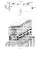
- Fig. 3 represents the replacement image, wherein the charged capacitors C 1 are discharged with a semiconductor switch TH 1 via a choke coil L 1 in uncharged capacitors C 2 .
- the unsaturated inductance L 2 carries a very small current. The limited by the inductor lower current increase allows the use of wear-resistant semiconductor switches.
- the charged capacitors C 2 discharge via the now saturated inductance L 2 in the forming coil L Umf .
- the area of the material interspersed with the magnetic flux is dimensioned such that the saturation occurs precisely when the capacitors C 2 in the equivalent circuit are charged to maximum voltage.
- the outer rails form the return conductor.
- the inner conductor remains free of force, the outer conductors are less burdened by the greater distance.
- the required area, d. H. the cross section through the core is determined by the saturation induction.
- Iron-cobalt alloys achieve very large saturation inductions of up to 2.5 T, but are unattractive because of their high purchase price. A cheaper one
- An advantage of this arrangement is that the saturable inductance can be modular and thus easily scalable.
Landscapes
- Physics & Mathematics (AREA)
- Nonlinear Science (AREA)
- Generation Of Surge Voltage And Current (AREA)
- Magnetic Resonance Imaging Apparatus (AREA)
Abstract
Description
- Die Erfindung betrifft eine Vorrichtung zur Erzeugung und Leitung eines hohen pulsförmigen elektrischen Stromes, die z. B. zum elektromagnetischen Umformen von Werkstücken verwendet werden kann.
- Die elektromagnetische Pulsumformung (EMP) ist ein seit langem bekanntes Verfahren [Dietz, H., Lippmann, H. J., Schenk, H.: "Messung der magnetischen Induktion in einer Magneform-Kompressionsspule" Elektrotechnische Zeitung - Bd. 88 Heft 19, S. 51-54]. Bei der Entwicklung von EMP-Anlagen müssen nicht nur die auftretenden Umformkräfte, sondern auch die hohen elektrischen Spannungen und Ströme beachten werden. Dadurch sind die Anlagen meist sehr komplex. Durch eine Weiterentwicklung der EMP-Technologie ergeben sich neue bzw. verbesserte Möglichkeiten bei der Bauteilfertigung, speziell für Leichtbaubauweisen, in der Automobil- oder deren Zulieferindustrie, der Luft-und Raumfahrtindustrie, bei in der Medizin oder Chemie verwendeten Anlagen und Geräten.
- Beim E M P werden Werkstücke mit magnetischen Feldern umgeformt, wobei impulsförmige Ströme hoher Amplitude durch eine Spule geführt werden. Pulsgeneratoren erzeugen aus geladenen Energiespeichern (z. B. Kondensatoren) beim Anschließen von Induktivitäten (z. B. Umforminduktivität) die erforderlichen hohen impulsförmigen Ströme. Dazu werden die Kondensatoren über spezielle Ladegeräte geladen. Ein Schalter startet dann die Energieübertragung aus dem Kondensator in eine Induktivität (Umformspule) (Bild 1). Zum Erreichen sehr hoher Pulsströme sind kleine Induktivitäten erforderlich, wobei die Reduktion der Kabelinduktivität mittels einer Parallelschaltung von Kabeln erreicht werden kann.
- Allerdings sind die heute zur Verfügung stehenden Pulsstromparameter noch so eingeschränkt, dass gerade eine Vielzahl höherwertiger fester Werkstoffe nicht bearbeitet werden können.
- Als Schalter für diese hohen Ströme verwendet man Ignitrons, Thyratrons oder Funkenstrecken. [
US 3,786,334 A ]. Der Nachteil dieser Schalter ist der der hohe Verschleiß. Sie sind durch die hohen Wartungs- und Wechselintervalle nicht anwenderfreundlich. Aus sicherungstechnischen Gründen können auch bestimmte Schalter nicht verwendet werden (z. B. Quecksilber aus Arbeitsschutzgründen). Verschleißarme bzw. verschleißfreie Halbleiterschalter (z. B. Thyristoren) bieten sich als Lösung an. Diese sind sehr teuer und besitzen begrenzte maximale Stromänderungsgeschwindigkeiten, so dass deren Einsatz nur selten erfolgt. - Aufgabe der Erfindung ist es, eine kostengünstige technische Lösung anzugeben, die die Verwendung von verschleißfreien Schaltern zur elektromagnetischen Pulsumformung ermöglicht und ökonomisch vertretbar ist. Weiterhin soll eine voluminöse Parallelschaltung von vielen Kabeln vermieden werden.
- Die Aufgabe wird gelöst durch die im Patentanspruch 1 beschriebenen Merkmale. Vorteilhafte Ausführungen sind in den Unteransprüchen angegeben. Die Realisierung der Aufgabe erfolgt durch die Verwendung einer sättigbaren Induktivität, die zugleich als Zuleitung zwischen Kondensator und Umformspule dient.
- Die sättigbare Induktivität muss folgende Eigenschaften aufweisen:
- Im Einschaltmoment muss die Induktivität groß sein. Die Spannungshöhe muss damit einen ausreichend hohen Stromfluss ermöglichen.
- Nach der Sättigung muss die Induktivität möglichst verschwindend gering werden, um eine große Eigenfrequenz der Schaltung erreichen zu können.
- Die Erfindung wird mit Abbildungen erläutert.
- Abb. 1
- zeigt die typische Ersatzschaltung eines Pulsgenerators zur EMP mit Thyristoren.
- Abb. 2
- stellt den Ausschnitt zum Aufbau der sättigbaren Induktivität aus ferromagnetischen Kernen und Sammelschienen dar.
- Abb. 3
- gibt eine Ersatzschaltung für den in
Abb. 2 dargestellten Aufbau an. - Abb. 4
- stellt den Zusammenhang der Spannungen und Ströme für den Aufbau dar.
- Abb. 5
- gibt eine mögliche Umsetzung der Erfindung an.
- Die sättigbare Induktivität besteht, wie in
Abb. 2 dargestellt, aus einer inneren Sammelschiene oder Leitung, die den Strom zur Umforminduktivität hinführt. Um diese Sammelschiene oder Leitung wird das magnetisch sättigbare Material in Form von Ringbandkernen angebracht. Diese Ringbandkerne können auch aus mehreren Teilkernen bestehen. - An einer Seite der sättigbaren Induktivität werden Sammelschienen oder Leitungen angebracht, die den Strom zurückführen. Eine weitere vorteilhafte Ausführung ist, dass die Stromzuführung an beiden Seiten oder an allen vier Seiten durch Sammelschienen oder Leitungen erfolgt.
-
Abb. 3 stellt das Ersatzbild dar, wobei, die geladenen Kondensatoren C 1 mit einem Halbleiterschalter TH 1 über eine Drosselspule L 1 in ungeladene Kondensatoren C 2 entladen werden. Die ungesättigte Induktivität L 2 führt einen sehr kleinen Strom. Der durch die Drosselspule begrenzte geringere Stromanstieg ermöglicht die Verwendung verschleißfreier Halbleiterschalter. Die geladenen Kondensatoren C 2 entladen sich über die mittlerweile gesättigte Induktivität L 2 in die Umformspule LUmf. - Optimaler Weise wird die Fläche des vom magnetischen Fluss durchsetzten Materials so bemessen, dass die Sättigung genau dann eintritt, wenn die Kondensatoren C2 in dem Ersatzschaltbild auf maximale Spannung geladen sind. Die Querschnittsfläche A des ferromagnetischen Materials berechnet sich über:

- In
Abb. 4 ist zu erkennen, dass der Strom durch die Umformspule L Umf größer als der Strom durch den Schalter Us wird. - Als Leiter der Induktivität werden rechteckige Stromschienen genutzt.
- Vorteilhaft ist die Verwendung einer Dreifachanordnung, bei der die äußeren Schienen den Rückleiter bilden. Der Innenleiter bleibt kraftfrei, die Außenleiter sind durch den größeren Abstand weniger belastet. Die erforderliche Fläche, d. h. der Querschnitt durch den Kern, wird durch die Sättigungsinduktion bestimmt. Hier ist es wichtig, Materialien mit hoher Sättigungsinduktion auszuwählen und die durch den Stromfluss hervorgerufene magnetische Feldstärke muss größer sein als die Sättigungsfeldstärke auf der kompletten Dimension des Kerns.
- Eisen-Kobalt-Legierungen erreichen sehr große Sättigungsinduktionen von bis zu 2,5 T, sind wegen ihres hohen Anschaffungspreises aber unattraktiv. Ein kostengünstiger
- Vertreter ist zum Beispiel die kornorientierte Eisen-Silizium-Legierung 30PH105, die eine Sättigungsinduktion von Bs= 2,03 T hat.
- Eine weitere vorteilhafte Ausführung der Erfindung ist, die Kerne der Drosselspulen mit einer magnetisch negativen Vorsättigung durch Ausnutzen der Remanenz zu versehen. Dadurch verringert sich die nötige Querschnittsfläche A

mit BRem als negative Remanenzinduktion. - Für die Erzeugung der Remanzinduktion gibt es folgende Möglichkeiten.
- a) In der Ruhezeit zwischen den Pulsen werden die Induktivitäten (die Hauptleiter) mittels eines eingespeisten negativen Gleichstroms oder entsprechender negativer Gleichstrompulse in den Remanenzzustand versetzt.
- b) Ein negativen Gleichstrom bzw. negative Gleichstrompulse werden während des Pulsens in die Induktivitäten eingespeist oder als konstanter negativer Gleichstrom bzw. als konstante Gleichstrompulse aufgeprägt.
- c) Der Kern wird mit einer Zusatzwicklung ausgeführt. Diese Zusatzwicklung wird wie in a) angegeben in den Ruhezeiten zwischen den Pulsen mit einem negativen Gleichstrom oder negativer Gleichstrompulse beaufschlagt.
- d) Die Zusatzwicklung wird, wie in b) angegeben, während des Pulsens mit negativem Gleichstrom bzw. mit negativen Gleichstrompulsen gespeist. Auch eine konstante Aufschaltung mit negativem Gleichstrom oder negativer Gleichstrompulse ist möglich.
- Ein Vorteil dieser Anordnung ist, dass die sättigbare Induktivität modular aufgebaut werden kann und damit leicht skalierbar ist.
Claims (3)
- Vorrichtung zur Stromverstärkung für die elektromanetische Pulsumformung bestehend aus einer Leitung und mindestens einem magnetisch sättigbaren Kern, dadurch gekennzeichnet, dass die Leitung aus Stromschienen besteht und dass der magnetisch sättigbare Kern aus einem Material mit einer sehr großen Sättigungsinduktion besteht.
- Vorrichtung nach Anspruch 1, dadurch gekennzeichnet, dass eine Zusatzwicklung auf dem sättigbaren Kern aufgebracht wird.
- Verwendung der Vorrichtung nach Anspruch 1 oder Anspruch 2, dadurch gekennzeichnet, dass eine Remanenzinduktion erzeugt wird.
Applications Claiming Priority (1)
| Application Number | Priority Date | Filing Date | Title |
|---|---|---|---|
| DE201010001934 DE102010001934A1 (de) | 2010-02-15 | 2010-02-15 | Vorrichtung zur Stromverstärkung für die elektromagnetische Pulsumformung und Verwendung |
Publications (3)
| Publication Number | Publication Date |
|---|---|
| EP2383756A2 true EP2383756A2 (de) | 2011-11-02 |
| EP2383756A3 EP2383756A3 (de) | 2012-09-05 |
| EP2383756B1 EP2383756B1 (de) | 2014-10-22 |
Family
ID=44317013
Family Applications (1)
| Application Number | Title | Priority Date | Filing Date |
|---|---|---|---|
| EP20110154545 Active EP2383756B1 (de) | 2010-02-15 | 2011-02-15 | Vorrichtung zur Stromverstärkung für die elektromagnetische Pulsumformung und Verwendung |
Country Status (2)
| Country | Link |
|---|---|
| EP (1) | EP2383756B1 (de) |
| DE (1) | DE102010001934A1 (de) |
Citations (1)
| Publication number | Priority date | Publication date | Assignee | Title |
|---|---|---|---|---|
| US3786334A (en) | 1971-08-12 | 1974-01-15 | Megapulse Inc | Magnetic pulse compression radio-frequency generator apparatus |
Family Cites Families (5)
| Publication number | Priority date | Publication date | Assignee | Title |
|---|---|---|---|---|
| GB534667A (en) * | 1939-09-11 | 1941-03-13 | British Thomson Houston Co Ltd | Improvements in and relating to directional saturable reactors |
| US5011553A (en) * | 1989-07-14 | 1991-04-30 | Allied-Signal, Inc. | Iron-rich metallic glasses having high saturation induction and superior soft ferromagnetic properties |
| US5684341A (en) * | 1993-08-07 | 1997-11-04 | Magnet-Physik Dr. Steingroever Gmbh | Electromagnetic generator for fast current and magnetic field pulses, for example, for use in magnetic metal working |
| DE19602951C2 (de) * | 1996-01-27 | 2000-12-07 | Steingroever Magnet Physik | Verfahren und Vorrichtung zum Aufweiten von Rohren oder rohrförmigen Teilen durch das Magnetfeld eines Strom-Impulses |
| DE19715351A1 (de) * | 1997-04-12 | 1998-10-15 | Steingroever Magnet Physik | Verfahren und Vorrichtung zum Herstellen von metallischen Hohlkörpern mit Beul-Struktur |
-
2010
- 2010-02-15 DE DE201010001934 patent/DE102010001934A1/de not_active Withdrawn
-
2011
- 2011-02-15 EP EP20110154545 patent/EP2383756B1/de active Active
Patent Citations (1)
| Publication number | Priority date | Publication date | Assignee | Title |
|---|---|---|---|---|
| US3786334A (en) | 1971-08-12 | 1974-01-15 | Megapulse Inc | Magnetic pulse compression radio-frequency generator apparatus |
Non-Patent Citations (1)
| Title |
|---|
| DIETZ, H.; LIPPMANN, H. J.; SCHENK, H.: "Messung der magnetischen Induktion in einer Magneform-Kompressionsspule", ELEKTROTECHNISCHE ZEITUNG, vol. 88, pages 51 - 54 |
Also Published As
| Publication number | Publication date |
|---|---|
| EP2383756B1 (de) | 2014-10-22 |
| DE102010001934A1 (de) | 2011-08-18 |
| EP2383756A3 (de) | 2012-09-05 |
Similar Documents
| Publication | Publication Date | Title |
|---|---|---|
| EP3619800B1 (de) | Inverter | |
| DE102009031665B4 (de) | Elektrodynamischer Aktor | |
| DE2306917A1 (de) | Induktive stromkreiskomponente | |
| EP2194629B1 (de) | Verfahren zur Störstromkompensation eines elektrischen Systems sowie Störstromkompensationseinrichtung | |
| DE102012014266A1 (de) | Magnetisch-induktives Durchflussmessgerät | |
| DE1082336B (de) | Kurzschliesser zum Schutz elektrischer Geraete | |
| EP2383756B1 (de) | Vorrichtung zur Stromverstärkung für die elektromagnetische Pulsumformung und Verwendung | |
| DE102012107534A1 (de) | Magnetisch-induktives Durchflussmessgerät | |
| EP2040512B1 (de) | Vorrichtung und Verfahren zum induktiven Erwärmen eines elektrisch leitenden Werkstücks | |
| EP2439012B1 (de) | Verfahren und Vorrichtung zum Betreiben einer Widerstandschweissvorrichtung | |
| DE102011052923B4 (de) | Energieübertragungseinheit | |
| DE1206536B (de) | Vorrichtung zum Abschalten von Kernreaktoren mit einem elektromagnetischen Stossimpulsgeber | |
| DE960559C (de) | Schaltdrossel | |
| EP0656637B1 (de) | Transformator mit rahmenförmigem Blechpaket | |
| DE4222678C2 (de) | Verfahren und Vorrichtung zur Elektroenergieerzeugung | |
| DE102020108562A1 (de) | Vorrichtung zur Wandlung von Energie aus dem Quantenvakuum | |
| DE102017109149A1 (de) | Vorrichtung und Verfahren zum Entmagnetisieren von Objekten | |
| DE754464C (de) | UEbertragungsmagnet fuer Wechselstromzugbeeinflussung | |
| DE102024108557A1 (de) | System und Verfahren zur Entmagnetisierung eines ferromagnetischen Bauteils | |
| DE102023106704A1 (de) | Schweißstromquelle | |
| DE678034C (de) | Eisendrosselspule | |
| DE286089C (de) | ||
| DE245842C (de) | ||
| DE502770C (de) | Einrichtung zur Kompensation des Erdschlussstromes von Hochspannungsleitungen | |
| DE19847272B4 (de) | Verfahren zum Herstellen von Sintermetallkernen |
Legal Events
| Date | Code | Title | Description |
|---|---|---|---|
| AK | Designated contracting states |
Kind code of ref document: A2 Designated state(s): AL AT BE BG CH CY CZ DE DK EE ES FI FR GB GR HR HU IE IS IT LI LT LU LV MC MK MT NL NO PL PT RO RS SE SI SK SM TR |
|
| AX | Request for extension of the european patent |
Extension state: BA ME |
|
| PUAI | Public reference made under article 153(3) epc to a published international application that has entered the european phase |
Free format text: ORIGINAL CODE: 0009012 |
|
| PUAL | Search report despatched |
Free format text: ORIGINAL CODE: 0009013 |
|
| AK | Designated contracting states |
Kind code of ref document: A3 Designated state(s): AL AT BE BG CH CY CZ DE DK EE ES FI FR GB GR HR HU IE IS IT LI LT LU LV MC MK MT NL NO PL PT RO RS SE SI SK SM TR |
|
| AX | Request for extension of the european patent |
Extension state: BA ME |
|
| RIC1 | Information provided on ipc code assigned before grant |
Ipc: H01F 29/14 20060101AFI20120727BHEP Ipc: H02M 1/16 20060101ALI20120727BHEP |
|
| 17P | Request for examination filed |
Effective date: 20130130 |
|
| 17Q | First examination report despatched |
Effective date: 20130411 |
|
| GRAP | Despatch of communication of intention to grant a patent |
Free format text: ORIGINAL CODE: EPIDOSNIGR1 |
|
| INTG | Intention to grant announced |
Effective date: 20131023 |
|
| GRAP | Despatch of communication of intention to grant a patent |
Free format text: ORIGINAL CODE: EPIDOSNIGR1 |
|
| INTG | Intention to grant announced |
Effective date: 20140514 |
|
| GRAS | Grant fee paid |
Free format text: ORIGINAL CODE: EPIDOSNIGR3 |
|
| GRAA | (expected) grant |
Free format text: ORIGINAL CODE: 0009210 |
|
| AK | Designated contracting states |
Kind code of ref document: B1 Designated state(s): AL AT BE BG CH CY CZ DE DK EE ES FI FR GB GR HR HU IE IS IT LI LT LU LV MC MK MT NL NO PL PT RO RS SE SI SK SM TR |
|
| AX | Request for extension of the european patent |
Extension state: BA ME |
|
| REG | Reference to a national code |
Ref country code: GB Ref legal event code: FG4D Free format text: NOT ENGLISH |
|
| REG | Reference to a national code |
Ref country code: CH Ref legal event code: EP |
|
| REG | Reference to a national code |
Ref country code: AT Ref legal event code: REF Ref document number: 692967 Country of ref document: AT Kind code of ref document: T Effective date: 20141115 |
|
| REG | Reference to a national code |
Ref country code: IE Ref legal event code: FG4D Free format text: LANGUAGE OF EP DOCUMENT: GERMAN |
|
| REG | Reference to a national code |
Ref country code: DE Ref legal event code: R096 Ref document number: 502011004732 Country of ref document: DE Effective date: 20141204 |
|
| REG | Reference to a national code |
Ref country code: NL Ref legal event code: VDEP Effective date: 20141022 |
|
| REG | Reference to a national code |
Ref country code: LT Ref legal event code: MG4D |
|
| PG25 | Lapsed in a contracting state [announced via postgrant information from national office to epo] |
Ref country code: NL Free format text: LAPSE BECAUSE OF FAILURE TO SUBMIT A TRANSLATION OF THE DESCRIPTION OR TO PAY THE FEE WITHIN THE PRESCRIBED TIME-LIMIT Effective date: 20141022 Ref country code: FI Free format text: LAPSE BECAUSE OF FAILURE TO SUBMIT A TRANSLATION OF THE DESCRIPTION OR TO PAY THE FEE WITHIN THE PRESCRIBED TIME-LIMIT Effective date: 20141022 Ref country code: NO Free format text: LAPSE BECAUSE OF FAILURE TO SUBMIT A TRANSLATION OF THE DESCRIPTION OR TO PAY THE FEE WITHIN THE PRESCRIBED TIME-LIMIT Effective date: 20150122 Ref country code: LT Free format text: LAPSE BECAUSE OF FAILURE TO SUBMIT A TRANSLATION OF THE DESCRIPTION OR TO PAY THE FEE WITHIN THE PRESCRIBED TIME-LIMIT Effective date: 20141022 Ref country code: PT Free format text: LAPSE BECAUSE OF FAILURE TO SUBMIT A TRANSLATION OF THE DESCRIPTION OR TO PAY THE FEE WITHIN THE PRESCRIBED TIME-LIMIT Effective date: 20150223 Ref country code: IS Free format text: LAPSE BECAUSE OF FAILURE TO SUBMIT A TRANSLATION OF THE DESCRIPTION OR TO PAY THE FEE WITHIN THE PRESCRIBED TIME-LIMIT Effective date: 20150222 Ref country code: ES Free format text: LAPSE BECAUSE OF FAILURE TO SUBMIT A TRANSLATION OF THE DESCRIPTION OR TO PAY THE FEE WITHIN THE PRESCRIBED TIME-LIMIT Effective date: 20141022 |
|
| PG25 | Lapsed in a contracting state [announced via postgrant information from national office to epo] |
Ref country code: RS Free format text: LAPSE BECAUSE OF FAILURE TO SUBMIT A TRANSLATION OF THE DESCRIPTION OR TO PAY THE FEE WITHIN THE PRESCRIBED TIME-LIMIT Effective date: 20141022 Ref country code: PL Free format text: LAPSE BECAUSE OF FAILURE TO SUBMIT A TRANSLATION OF THE DESCRIPTION OR TO PAY THE FEE WITHIN THE PRESCRIBED TIME-LIMIT Effective date: 20141022 Ref country code: CY Free format text: LAPSE BECAUSE OF FAILURE TO SUBMIT A TRANSLATION OF THE DESCRIPTION OR TO PAY THE FEE WITHIN THE PRESCRIBED TIME-LIMIT Effective date: 20141022 Ref country code: HR Free format text: LAPSE BECAUSE OF FAILURE TO SUBMIT A TRANSLATION OF THE DESCRIPTION OR TO PAY THE FEE WITHIN THE PRESCRIBED TIME-LIMIT Effective date: 20141022 Ref country code: LV Free format text: LAPSE BECAUSE OF FAILURE TO SUBMIT A TRANSLATION OF THE DESCRIPTION OR TO PAY THE FEE WITHIN THE PRESCRIBED TIME-LIMIT Effective date: 20141022 Ref country code: SE Free format text: LAPSE BECAUSE OF FAILURE TO SUBMIT A TRANSLATION OF THE DESCRIPTION OR TO PAY THE FEE WITHIN THE PRESCRIBED TIME-LIMIT Effective date: 20141022 Ref country code: GR Free format text: LAPSE BECAUSE OF FAILURE TO SUBMIT A TRANSLATION OF THE DESCRIPTION OR TO PAY THE FEE WITHIN THE PRESCRIBED TIME-LIMIT Effective date: 20150123 |
|
| REG | Reference to a national code |
Ref country code: DE Ref legal event code: R097 Ref document number: 502011004732 Country of ref document: DE |
|
| PG25 | Lapsed in a contracting state [announced via postgrant information from national office to epo] |
Ref country code: DK Free format text: LAPSE BECAUSE OF FAILURE TO SUBMIT A TRANSLATION OF THE DESCRIPTION OR TO PAY THE FEE WITHIN THE PRESCRIBED TIME-LIMIT Effective date: 20141022 Ref country code: SK Free format text: LAPSE BECAUSE OF FAILURE TO SUBMIT A TRANSLATION OF THE DESCRIPTION OR TO PAY THE FEE WITHIN THE PRESCRIBED TIME-LIMIT Effective date: 20141022 Ref country code: CZ Free format text: LAPSE BECAUSE OF FAILURE TO SUBMIT A TRANSLATION OF THE DESCRIPTION OR TO PAY THE FEE WITHIN THE PRESCRIBED TIME-LIMIT Effective date: 20141022 Ref country code: EE Free format text: LAPSE BECAUSE OF FAILURE TO SUBMIT A TRANSLATION OF THE DESCRIPTION OR TO PAY THE FEE WITHIN THE PRESCRIBED TIME-LIMIT Effective date: 20141022 Ref country code: RO Free format text: LAPSE BECAUSE OF FAILURE TO SUBMIT A TRANSLATION OF THE DESCRIPTION OR TO PAY THE FEE WITHIN THE PRESCRIBED TIME-LIMIT Effective date: 20141022 |
|
| PLBE | No opposition filed within time limit |
Free format text: ORIGINAL CODE: 0009261 |
|
| STAA | Information on the status of an ep patent application or granted ep patent |
Free format text: STATUS: NO OPPOSITION FILED WITHIN TIME LIMIT |
|
| PG25 | Lapsed in a contracting state [announced via postgrant information from national office to epo] |
Ref country code: IT Free format text: LAPSE BECAUSE OF FAILURE TO SUBMIT A TRANSLATION OF THE DESCRIPTION OR TO PAY THE FEE WITHIN THE PRESCRIBED TIME-LIMIT Effective date: 20141022 |
|
| 26N | No opposition filed |
Effective date: 20150723 |
|
| PG25 | Lapsed in a contracting state [announced via postgrant information from national office to epo] |
Ref country code: LU Free format text: LAPSE BECAUSE OF FAILURE TO SUBMIT A TRANSLATION OF THE DESCRIPTION OR TO PAY THE FEE WITHIN THE PRESCRIBED TIME-LIMIT Effective date: 20150215 |
|
| REG | Reference to a national code |
Ref country code: CH Ref legal event code: PL |
|
| GBPC | Gb: european patent ceased through non-payment of renewal fee |
Effective date: 20150215 |
|
| PG25 | Lapsed in a contracting state [announced via postgrant information from national office to epo] |
Ref country code: LI Free format text: LAPSE BECAUSE OF NON-PAYMENT OF DUE FEES Effective date: 20150228 Ref country code: CH Free format text: LAPSE BECAUSE OF NON-PAYMENT OF DUE FEES Effective date: 20150228 Ref country code: MC Free format text: LAPSE BECAUSE OF FAILURE TO SUBMIT A TRANSLATION OF THE DESCRIPTION OR TO PAY THE FEE WITHIN THE PRESCRIBED TIME-LIMIT Effective date: 20141022 |
|
| REG | Reference to a national code |
Ref country code: IE Ref legal event code: MM4A |
|
| PG25 | Lapsed in a contracting state [announced via postgrant information from national office to epo] |
Ref country code: IE Free format text: LAPSE BECAUSE OF NON-PAYMENT OF DUE FEES Effective date: 20150215 Ref country code: GB Free format text: LAPSE BECAUSE OF NON-PAYMENT OF DUE FEES Effective date: 20150215 |
|
| REG | Reference to a national code |
Ref country code: FR Ref legal event code: PLFP Year of fee payment: 6 |
|
| PG25 | Lapsed in a contracting state [announced via postgrant information from national office to epo] |
Ref country code: SI Free format text: LAPSE BECAUSE OF FAILURE TO SUBMIT A TRANSLATION OF THE DESCRIPTION OR TO PAY THE FEE WITHIN THE PRESCRIBED TIME-LIMIT Effective date: 20141022 |
|
| PG25 | Lapsed in a contracting state [announced via postgrant information from national office to epo] |
Ref country code: MT Free format text: LAPSE BECAUSE OF FAILURE TO SUBMIT A TRANSLATION OF THE DESCRIPTION OR TO PAY THE FEE WITHIN THE PRESCRIBED TIME-LIMIT Effective date: 20141022 |
|
| REG | Reference to a national code |
Ref country code: FR Ref legal event code: PLFP Year of fee payment: 7 |
|
| REG | Reference to a national code |
Ref country code: AT Ref legal event code: MM01 Ref document number: 692967 Country of ref document: AT Kind code of ref document: T Effective date: 20160215 |
|
| PG25 | Lapsed in a contracting state [announced via postgrant information from national office to epo] |
Ref country code: HU Free format text: LAPSE BECAUSE OF FAILURE TO SUBMIT A TRANSLATION OF THE DESCRIPTION OR TO PAY THE FEE WITHIN THE PRESCRIBED TIME-LIMIT; INVALID AB INITIO Effective date: 20110215 Ref country code: BG Free format text: LAPSE BECAUSE OF FAILURE TO SUBMIT A TRANSLATION OF THE DESCRIPTION OR TO PAY THE FEE WITHIN THE PRESCRIBED TIME-LIMIT Effective date: 20141022 Ref country code: SM Free format text: LAPSE BECAUSE OF FAILURE TO SUBMIT A TRANSLATION OF THE DESCRIPTION OR TO PAY THE FEE WITHIN THE PRESCRIBED TIME-LIMIT Effective date: 20141022 Ref country code: AT Free format text: LAPSE BECAUSE OF NON-PAYMENT OF DUE FEES Effective date: 20160215 |
|
| REG | Reference to a national code |
Ref country code: DE Ref legal event code: R082 Ref document number: 502011004732 Country of ref document: DE |
|
| PG25 | Lapsed in a contracting state [announced via postgrant information from national office to epo] |
Ref country code: BE Free format text: LAPSE BECAUSE OF NON-PAYMENT OF DUE FEES Effective date: 20150228 |
|
| PG25 | Lapsed in a contracting state [announced via postgrant information from national office to epo] |
Ref country code: TR Free format text: LAPSE BECAUSE OF FAILURE TO SUBMIT A TRANSLATION OF THE DESCRIPTION OR TO PAY THE FEE WITHIN THE PRESCRIBED TIME-LIMIT Effective date: 20141022 |
|
| REG | Reference to a national code |
Ref country code: FR Ref legal event code: PLFP Year of fee payment: 8 |
|
| PGFP | Annual fee paid to national office [announced via postgrant information from national office to epo] |
Ref country code: DE Payment date: 20180228 Year of fee payment: 8 |
|
| PGFP | Annual fee paid to national office [announced via postgrant information from national office to epo] |
Ref country code: FR Payment date: 20180226 Year of fee payment: 8 |
|
| PG25 | Lapsed in a contracting state [announced via postgrant information from national office to epo] |
Ref country code: MK Free format text: LAPSE BECAUSE OF FAILURE TO SUBMIT A TRANSLATION OF THE DESCRIPTION OR TO PAY THE FEE WITHIN THE PRESCRIBED TIME-LIMIT Effective date: 20141022 |
|
| PG25 | Lapsed in a contracting state [announced via postgrant information from national office to epo] |
Ref country code: AL Free format text: LAPSE BECAUSE OF FAILURE TO SUBMIT A TRANSLATION OF THE DESCRIPTION OR TO PAY THE FEE WITHIN THE PRESCRIBED TIME-LIMIT Effective date: 20141022 |
|
| REG | Reference to a national code |
Ref country code: DE Ref legal event code: R119 Ref document number: 502011004732 Country of ref document: DE |
|
| PG25 | Lapsed in a contracting state [announced via postgrant information from national office to epo] |
Ref country code: DE Free format text: LAPSE BECAUSE OF NON-PAYMENT OF DUE FEES Effective date: 20190903 |
|
| PG25 | Lapsed in a contracting state [announced via postgrant information from national office to epo] |
Ref country code: FR Free format text: LAPSE BECAUSE OF NON-PAYMENT OF DUE FEES Effective date: 20190228 |