EP2383384A1 - Wäschetrockner - Google Patents
Wäschetrockner Download PDFInfo
- Publication number
- EP2383384A1 EP2383384A1 EP11175831A EP11175831A EP2383384A1 EP 2383384 A1 EP2383384 A1 EP 2383384A1 EP 11175831 A EP11175831 A EP 11175831A EP 11175831 A EP11175831 A EP 11175831A EP 2383384 A1 EP2383384 A1 EP 2383384A1
- Authority
- EP
- European Patent Office
- Prior art keywords
- air
- air path
- clothes dryer
- cabinet
- heat
- Prior art date
- Legal status (The legal status is an assumption and is not a legal conclusion. Google has not performed a legal analysis and makes no representation as to the accuracy of the status listed.)
- Granted
Links
Images


Classifications
-
- D—TEXTILES; PAPER
- D06—TREATMENT OF TEXTILES OR THE LIKE; LAUNDERING; FLEXIBLE MATERIALS NOT OTHERWISE PROVIDED FOR
- D06F—LAUNDERING, DRYING, IRONING, PRESSING OR FOLDING TEXTILE ARTICLES
- D06F58/00—Domestic laundry dryers
- D06F58/20—General details of domestic laundry dryers
- D06F58/206—Heat pump arrangements
-
- D—TEXTILES; PAPER
- D06—TREATMENT OF TEXTILES OR THE LIKE; LAUNDERING; FLEXIBLE MATERIALS NOT OTHERWISE PROVIDED FOR
- D06F—LAUNDERING, DRYING, IRONING, PRESSING OR FOLDING TEXTILE ARTICLES
- D06F2103/00—Parameters monitored or detected for the control of domestic laundry washing machines, washer-dryers or laundry dryers
- D06F2103/02—Characteristics of laundry or load
- D06F2103/08—Humidity
-
- D—TEXTILES; PAPER
- D06—TREATMENT OF TEXTILES OR THE LIKE; LAUNDERING; FLEXIBLE MATERIALS NOT OTHERWISE PROVIDED FOR
- D06F—LAUNDERING, DRYING, IRONING, PRESSING OR FOLDING TEXTILE ARTICLES
- D06F2103/00—Parameters monitored or detected for the control of domestic laundry washing machines, washer-dryers or laundry dryers
- D06F2103/28—Air properties
- D06F2103/32—Temperature
-
- D—TEXTILES; PAPER
- D06—TREATMENT OF TEXTILES OR THE LIKE; LAUNDERING; FLEXIBLE MATERIALS NOT OTHERWISE PROVIDED FOR
- D06F—LAUNDERING, DRYING, IRONING, PRESSING OR FOLDING TEXTILE ARTICLES
- D06F2103/00—Parameters monitored or detected for the control of domestic laundry washing machines, washer-dryers or laundry dryers
- D06F2103/28—Air properties
- D06F2103/34—Humidity
-
- D—TEXTILES; PAPER
- D06—TREATMENT OF TEXTILES OR THE LIKE; LAUNDERING; FLEXIBLE MATERIALS NOT OTHERWISE PROVIDED FOR
- D06F—LAUNDERING, DRYING, IRONING, PRESSING OR FOLDING TEXTILE ARTICLES
- D06F2103/00—Parameters monitored or detected for the control of domestic laundry washing machines, washer-dryers or laundry dryers
- D06F2103/28—Air properties
- D06F2103/36—Flow or velocity
-
- D—TEXTILES; PAPER
- D06—TREATMENT OF TEXTILES OR THE LIKE; LAUNDERING; FLEXIBLE MATERIALS NOT OTHERWISE PROVIDED FOR
- D06F—LAUNDERING, DRYING, IRONING, PRESSING OR FOLDING TEXTILE ARTICLES
- D06F2105/00—Systems or parameters controlled or affected by the control systems of washing machines, washer-dryers or laundry dryers
- D06F2105/16—Air properties
- D06F2105/24—Flow or velocity
-
- D—TEXTILES; PAPER
- D06—TREATMENT OF TEXTILES OR THE LIKE; LAUNDERING; FLEXIBLE MATERIALS NOT OTHERWISE PROVIDED FOR
- D06F—LAUNDERING, DRYING, IRONING, PRESSING OR FOLDING TEXTILE ARTICLES
- D06F2105/00—Systems or parameters controlled or affected by the control systems of washing machines, washer-dryers or laundry dryers
- D06F2105/32—Air flow control means
-
- D—TEXTILES; PAPER
- D06—TREATMENT OF TEXTILES OR THE LIKE; LAUNDERING; FLEXIBLE MATERIALS NOT OTHERWISE PROVIDED FOR
- D06F—LAUNDERING, DRYING, IRONING, PRESSING OR FOLDING TEXTILE ARTICLES
- D06F58/00—Domestic laundry dryers
- D06F58/02—Domestic laundry dryers having dryer drums rotating about a horizontal axis
-
- D—TEXTILES; PAPER
- D06—TREATMENT OF TEXTILES OR THE LIKE; LAUNDERING; FLEXIBLE MATERIALS NOT OTHERWISE PROVIDED FOR
- D06F—LAUNDERING, DRYING, IRONING, PRESSING OR FOLDING TEXTILE ARTICLES
- D06F58/00—Domestic laundry dryers
- D06F58/32—Control of operations performed in domestic laundry dryers
- D06F58/34—Control of operations performed in domestic laundry dryers characterised by the purpose or target of the control
- D06F58/36—Control of operational steps, e.g. for optimisation or improvement of operational steps depending on the condition of the laundry
- D06F58/38—Control of operational steps, e.g. for optimisation or improvement of operational steps depending on the condition of the laundry of drying, e.g. to achieve the target humidity
Definitions
- the present invention relates to a clothes dryer, and more particularly, to a clothes dryer of exhaust type including a vapor compression cycle system.
- the clothes dryer improves drying efficiency by drying laundry by supplying heat to an introduced air from a heat exchange cycle system.
- Clothes dryers are mainly used to dry clothes by removing moisture from clothes that have just been washed.
- the clothes dryers can be classified into an exhaust type and a condensation type according to a processing method of moist air generated while drying laundry.
- the former type employs a method of exhausting moist air from a dryer, while the latter employs a method of removing moisture by condensing moist air exhausted from a dryer and circulating the moisture-removed air again in the dryer.
- an air intake duct and an air exhaust duct are connected to a rotatable drum disposed inside a cabinet, the air intake duct having a heater disposed therein.
- the condensation type clothes dryer has a merit that it can be manufactured in a built-in, type since it requires no air exhaust duct for discharging air out of the clothes dryer, while it has a drawback that it requires a long drying time and is difficult to be manufactured to have a large capacity although its energy efficiency is higher than the exhaust type.
- an object of the present invention is to provide a clothes dryer which improves energy efficiency and has little possibility of causing a damage to laundry due to a high temperature air in a drying procedure.
- Another object of the present invention is to provide a clothes dryer which can exhaust air that has been dried to the outside with moisture removed enough from the dried air.
- Still another object of the present invention is to provide a clothes dryer which is compact with improved space utilization.
- a clothes dryer comprising: a cabinet; a drying container rotationally mounted in the cabinet; a driving portion for supplying a torque to the drying container; a first air path connected to one side of the drying container; a second air path connected to the other side of the drying container and connected to outside of the cabinet; a first heat exchange portion for exchanging heat with air flowing through the first air path; and a second heat exchange portion for exchanging heat with air flowing through the second air path, wherein the first air path and the second air path are located below the drying container.
- the first heat exchange portion increases the temperature of flowing air through a heat exchange
- the second heat exchange portion removes moisture from flowing air through a heat exchange.
- the first heat exchange portion and the second heat exchange portion form a thermodynamic cycle by a compressor and an expansion unit disposed inside the cabinet and a pipe connecting the compressor and the expansion unit.
- An opening for putting laundry in and out the drying container is formed in the front face of the cabinet.
- a fan for creating an air flow is disposed at at least one of the first and second air paths.
- the fan receives a torque from the driving portion.
- a cabinet comprising: a cabinet; a drying container rotationally mounted in the cabinet; a driving portion for supplying a torque to the drying container; a first air path connected to one side of the drying container; a second air path connected to the other side of the drying container and connected to outside of the cabinet; a first heat exchange portion for exchanging heat with air flowing through the first air path; and a second heat exchange portion for exchanging heat with air flowing through the second air path, wherein the second air path has a damper for opening and closing the paths disposed thereon.
- a temperature sensor or humidity sensor is disposed in front of the damper on the second air path.
- the damper is controlled in at least two states including an opened state and a closed state according to a predetermined value of a signal sensed by the temperature sensor or humidity sensor.
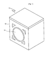
- FIG.1 one example of a clothes dryer 10 according to the present invention is illustrated.
- a cabinet 12 provided with an entrance 14 in the front face is hollow inside, with a drying container rotationally mounted therein.
- FIGs.2 and 3 illustrates an inner structure of the clothes dryer in more detail.
- the drying container 16 is a cylindrical-shaped structure, and disposed so as to rotate around an axis substantially parallel to the bottom of the cabinet 12.
- the drying container 16 is made rotatable by receiving a torque from a driving portion 18, e.g., a motor, disposed on a lower side thereof, preferably, on the bottom of the cabinet 12.
- a driving portion e.g., a motor
- a belt engaged by being extended from a driving shaft of the driving portion 18 to the outer peripheral surface of the drying container 16 is suitable.
- the driving portion is also able to transmit a torque to a fan 40 disposed inside the cabinet 12 and creating an air flow.
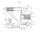
- FIG.4 illustrates various elements disposed on the bottom of the cabinet of the clothes dryer.
- a first air channel 20 through which intake air flows is connected to at one side of the drying container 16, and a second air path 22 through which exhaust air from the drying container flows is connected to the other side thereof.
- the entrance of the first air path 20 is not exposed out of the cabinet 12, but it is preferable that the outlet of the second air path 22 is exposed out of the cabinet 12.
- the shapes of the first air path 20 and second air path 22 are not specifically restricted, but the direction or position of each part of the paths may be changed so as to be suitable to the space in the cabinet.
- a first heat exchange portion 30 is disposed in the first air path 20.
- the first heat exchange portion 30 applies heat to air introduced into the first air path 20 to increase the air in temperature.
- the air passing through the first air path 20 enters the drying container 16 in a temperature-increased state.
- a second heat exchange portion 32 is disposed at the rear end of the second air path 22.
- the second heat exchange portion 32 takes heat away from the air exhausted from the drying container 16 via the second air path 22 to change the air to a moisture-removed state.
- the air having passed through the second heat exchange portion 32 is exhausted out of the cabinet 12, with moisture removed.
- the first heat exchange portion 30 and the second heat exchange portion 32 form a thermodynamic cycle.
- the cabinet 12 further includes a compressor 34 and an expansion device 36 are preferably disposed in the lower side of the drying container or lower than the drying container.
- the first heat exchange portion 30 and the second heat exchange portion 32 are connected by a pipe 38 to form one closed loop.
- Such a cycle is a kind of "vapor compression cycle", and serves as a heat pump with respect to air flowing through the first air channel 30.
- the air entering the first air path 20 enters the drying container after it is increased in temperature by receiving heat in the second heat exchange portion 32.
- a condenser for supplying heat to a flowing air is used as the first heat exchange portion 30, and an evaporator for absorbing heat from a flowing air so as to remove moisture from the air exhausted from the drying container is used as the second heat exchange portion 32.
- a plurality of heat exchange pins are generally mounted at the heat exchange portions 30 and 32 in order to increase a heat transfer area on the pipe through which refrigerant passes.
- a flowing air receives heat from the condenser and is increased to a temperature higher than about 50°C, preferably, 50 to 75°C.
- the temperature of air entering the drying container is lower than the case of a heater type, thereby not damaging laundry.
- the compressor 34 which is one of the elements of the vapor compressor cycle, may be located at various positions in the cabinet.
- the compressor 34 is located at the first air path 20 side. Especially, the compressor 34 is located in front of the first heat exchange portion 30. In this case, the heat generated from the compressor 34 firstly increases the temperature of the air entering the first air path 20, thus further increasing the temperature of air passing through the first heat exchange portion.
- the compressor 34 may be disposed at the second air path 22 side.
- the compressor 34 is disposed next to the second heat portion 32 at the second air path 22 side.
- the air having passes through the second heat exchange portion 32 cools the compressor 34, thereby increasing the overall efficiency of the vapor compressor cycle system.
- FIG.6 schematically illustrates a refrigerant flow and an air flow in the aforementioned cycle.
- a proper refrigerant flows in the pipe 38 for connecting each of the elements of the cycle.
- the refrigerant proceeds to the first heat exchange portion 30 from the second heat exchange portion 32 through the expansion device 36, and then proceeds to the second heat exchange portion 32 from the first heat exchange portion 30 through the compressor 34.
- This flow direction of the refrigerant is indicated by a dotted arrow.
- the air flowing into the first air path 20 passes through the first heat exchange portion 30 and enters the drying container 16, and then passes through the second heat exchange portion 32 via the second air path 22 and is exhausted out of the cabinet.
- This flow direction is indicated by a dotted arrow.
- each of the elements constituting the above cycle that is, the first heat exchange portion 30, the second heat exchange portion 32, the compressor 34, the expansion device, and the pipe 38 connecting them are all disposed inside the cabinet 12, especially, below the drying container 16.
- the first heat exchange portion 30 is disposed, and at least some parts of the second air path 22, where the second heat exchange portion 32 is disposed, are disposed below the drying container 16.
- FIG.7 illustrates some parts of the clothes dryer according to the present invention.
- a belt 42 is wound around the outer peripheral surface of the drying container 16, and the belt 42 is connected to a rotary shaft 18a of the driving portion 18 and transfers a torque to the drying container 16.
- the driving portion 18 is also connected to a fan 40 disposed on the second air path 22 to drive the fan.
- the driving portion 18 can rotate the drying container 16 and the fan 40 simultaneously.
- the drying container 16 and the fan 40 are driven at a time only by the one driving portion 18, so that the space utilization in the cabinet can be increased and no additional apparatus is required, which is advantageous.
- the fan 40 is disposed in the second air path 22 near the drying container 16, it may also be disposed on the first air path only if it can be supplied with a torque from the driving portion 18.
- a filter (21 of FIG.4 ) is disposed on the first air path 20 before the first heat exchange portion is disposed, so that it may remove contaminants, such as dusts, contained in an introduced air in advance.
- the air having passed through the first heat exchange 30 maintains a temperature of about 50 to 75°C.
- the high temperature air maintaining this degree of temperature can smoothly perform drying without damaging laundry in the drying container 16.
- the high temperature and low humidity introduced into the drying container 16 delivers heat while in contact with laundry containing moisture, and receives moisture from laundry and comes out of the drying container in the form of a high humidity air.
- a heat generating system using a vapor compression cycle exhibits heating performance two or three times larger as compared to a heater type, under the assumption that the same power is used.
- power consumption can be reduced.
- the efficiency of the vapor compression cycle system can be increased by disposing the compressor at the entrance of the first air path or at the exit of the second air path.
- the temperature of air introduced into the drying container is lower as compared to drying using a heater type, which causes less damage of laundry.
- the second heat exchange portion of the heat generating system removes moisture from exhausted air, which can avoid humid air from being exhausted into the building due to the operation of the dryer.
- An exhaust type dryer injects high temperature air to one side of a drying container, and discharges humid air to the other side thereof. Such a process is always the same from an initial stage of drying until an end stage of drying. If high temperature air stays in the drying container for a while and then is directly discharged out of the drying drum, this is not efficient in terms of energy utilization. That is, energy consumption is increased in the overall drying process.
- the energy efficiency is increased by controlling an air flow such that the time during which air stays in the drying container may differ depending on a drying procedure.
- a damper for opening and closing the paths is disposed on the second air path through which air is discharged to thus control an air flow.
- FIG.8 schematically illustrates some parts of the clothes dryer with a damper disposed thereto.
- a damper 60 is disposed near the drying container 16 on the second air path 22.
- a sensor 63 for sensing a temperature or humidity of air discharged from the drying container 16 is disposed in front of the damper 60.
- the damper 60 is controlled according to a temperature or humidity sensed by the sensor 62, thereby adjusting the flow of air passing through the second air path 22.
- a method of controlling the opening and closing of the damper can be selected variously according to a dried state of laundry or a state of the air discharged from the drying container.
- a degree of opening and closing the damper may be changed based on a saturation point Ps at which an increase rate of temperature sensed by the sensor becomes lower or a decrease rate of humidity becomes slow.
- the damper it is possible to control the damper to be closed if a measured temperature of an air outlet portion of the drying container is less than a predetermined temperature (i.e., 60°C) or control the damper to be opened if it is greater than the predetermined temperature. Besides, it is also possible to close the damper until a measured humidity of air discharged from the air outlet portion of the drying container reaches a predetermined value and open the damper if it exceeds the predetermined value.
- a predetermined temperature i.e. 60°C
- the damper is closed in an initial stage of drying to increase the time during which a high temperature air stays in the drying container, and the damper is opened in an intermediate or end stage of drying to increase a discharge amount of air. Therefore, there is a lot of time for which high temperature air is contacted with laundry in the initial stage of drying, thus even a small air flow can be efficiently utilized for drying. Further, in the intermediate or end stage of drying, the energy consumption can be reduced by decreasing an air heating degree rather than by increasing an air flow amount.
- the pressure in the drying container may be excessively increased or a large load may be applied to the fan for creating an air flow.
- the step of partially opening the damper may be included.
- a multistage damper control method may be used in which the damper is fully opened if a measured pressure in the drying container reaches a predetermined pressure or if a temperature or humidity reaches a predetermined value after the damper is slightly opened in advance when the temperature or humidity reaches a given value before the air outlet in the drying container reaches the predetermined temperature or humidity.
- the present invention can increase the energy efficiency of the dryer by including first and second heat exchange portions serving as heat pumps. Moreover, the present invention can remove moisture from air exhausted from the dryer.
- the internal structure of the dryer is utilized as its, and thus there is no need for volume increase. That is, the space required to dispose the system gets smaller as compared to the case where the system is disposed at a side or rear of the cabinet.
- the present invention can lengthen the time for which high temperature air stays in the drying drum by changing the degree of opening and closing the damper disposed between the drying container and the air path. Therefore, a lot of moisture can be removed from laundry; and the energy consumption of the dryer can be reduced.
Landscapes
- Engineering & Computer Science (AREA)
- Textile Engineering (AREA)
- Detail Structures Of Washing Machines And Dryers (AREA)
- Drying Of Solid Materials (AREA)
- Polarising Elements (AREA)
- Crystals, And After-Treatments Of Crystals (AREA)
- Woven Fabrics (AREA)
Priority Applications (3)
| Application Number | Priority Date | Filing Date | Title |
|---|---|---|---|
| EP11175831.4A EP2383384B1 (de) | 2004-12-06 | 2004-12-06 | Wäschetrockner |
| EP15152129.1A EP2891742B1 (de) | 2004-12-06 | 2004-12-06 | Wäschetrockner |
| ES11175831.4T ES2559956T3 (es) | 2004-12-06 | 2004-12-06 | Secador de ropa |
Applications Claiming Priority (3)
| Application Number | Priority Date | Filing Date | Title |
|---|---|---|---|
| EP11175831.4A EP2383384B1 (de) | 2004-12-06 | 2004-12-06 | Wäschetrockner |
| EP04808319A EP1819868B1 (de) | 2004-12-06 | 2004-12-06 | Wäschetrockner |
| PCT/KR2004/003188 WO2006062261A1 (en) | 2004-12-06 | 2004-12-06 | Clothes dryer |
Related Parent Applications (2)
| Application Number | Title | Priority Date | Filing Date |
|---|---|---|---|
| EP04808319.0 Division | 2004-12-06 | ||
| EP04808319A Division EP1819868B1 (de) | 2004-12-06 | 2004-12-06 | Wäschetrockner |
Related Child Applications (2)
| Application Number | Title | Priority Date | Filing Date |
|---|---|---|---|
| EP15152129.1A Division EP2891742B1 (de) | 2004-12-06 | 2004-12-06 | Wäschetrockner |
| EP15152129.1A Division-Into EP2891742B1 (de) | 2004-12-06 | 2004-12-06 | Wäschetrockner |
Publications (2)
| Publication Number | Publication Date |
|---|---|
| EP2383384A1 true EP2383384A1 (de) | 2011-11-02 |
| EP2383384B1 EP2383384B1 (de) | 2015-11-25 |
Family
ID=36578061
Family Applications (3)
| Application Number | Title | Priority Date | Filing Date |
|---|---|---|---|
| EP11175831.4A Not-in-force EP2383384B1 (de) | 2004-12-06 | 2004-12-06 | Wäschetrockner |
| EP04808319A Not-in-force EP1819868B1 (de) | 2004-12-06 | 2004-12-06 | Wäschetrockner |
| EP15152129.1A Not-in-force EP2891742B1 (de) | 2004-12-06 | 2004-12-06 | Wäschetrockner |
Family Applications After (2)
| Application Number | Title | Priority Date | Filing Date |
|---|---|---|---|
| EP04808319A Not-in-force EP1819868B1 (de) | 2004-12-06 | 2004-12-06 | Wäschetrockner |
| EP15152129.1A Not-in-force EP2891742B1 (de) | 2004-12-06 | 2004-12-06 | Wäschetrockner |
Country Status (6)
| Country | Link |
|---|---|
| US (2) | US8863400B2 (de) |
| EP (3) | EP2383384B1 (de) |
| CN (1) | CN1973077B (de) |
| AT (1) | ATE520816T1 (de) |
| ES (3) | ES2368431T3 (de) |
| WO (1) | WO2006062261A1 (de) |
Families Citing this family (31)
| Publication number | Priority date | Publication date | Assignee | Title |
|---|---|---|---|---|
| KR100662369B1 (ko) * | 2004-11-30 | 2007-01-02 | 엘지전자 주식회사 | 열풍공급용 옷걸이가 구비된 복합식 건조장치 |
| WO2006062262A1 (en) * | 2004-12-06 | 2006-06-15 | Lg Electronics Inc. | Clothes dryer |
| ATE428015T1 (de) * | 2006-02-21 | 2009-04-15 | Electrolux Home Prod Corp | Haushaltswaschetrockner mit einem zusatzlichen kondensator |
| US8024871B2 (en) * | 2006-11-08 | 2011-09-27 | Lg Electronics Inc. | Exhaust structure for clothes dryer in apartment building |
| KR100811487B1 (ko) * | 2007-02-13 | 2008-03-07 | 엘지전자 주식회사 | 덕트리스 건조기 |
| DE102007018787A1 (de) * | 2007-04-20 | 2008-10-23 | BSH Bosch und Siemens Hausgeräte GmbH | Verfahren zum Betrieb eines Kondensationstrockners mit einer Wärmepumpe, sowie hierzu geeigneter Kondensationstrockner |
| KR101308510B1 (ko) * | 2007-11-05 | 2013-09-12 | 동부대우전자 주식회사 | 히터 내장형 흡기관을 구비하는 건조기 |
| DE102007052839A1 (de) * | 2007-11-06 | 2009-05-07 | BSH Bosch und Siemens Hausgeräte GmbH | Trockner mit Wärmepumpenkreis |
| US20090205220A1 (en) * | 2008-02-20 | 2009-08-20 | Dewald Iii Charles Robert | Dryer and adapter having ducting system |
| TWI381077B (zh) * | 2009-10-22 | 2013-01-01 | Ind Tech Res Inst | 熱泵乾衣機及熱泵乾衣機之控制方法 |
| US8650770B1 (en) | 2010-06-17 | 2014-02-18 | George Samuel Levy | Air cycle heat pump dryer |
| PL2550390T3 (pl) * | 2010-08-09 | 2017-07-31 | Lg Electronics Inc. | Suszarka odzieży |
| EP2423371A1 (de) | 2010-08-25 | 2012-02-29 | Electrolux Home Products Corporation N.V. | Wäschebehandlungsmaschine |
| EP2423378B1 (de) | 2010-08-25 | 2013-04-17 | Electrolux Home Products Corporation N.V. | Wäschebehandlungsmaschine |
| KR101809130B1 (ko) * | 2011-03-29 | 2017-12-14 | 엘지전자 주식회사 | 의류건조기 |
| CN103820980B (zh) * | 2012-11-16 | 2017-09-22 | 青岛海尔洗衣机有限公司 | 一种干衣机及其烘干方法 |
| CN108691175B (zh) * | 2014-07-24 | 2020-11-27 | 博西华电器(江苏)有限公司 | 干衣机 |
| US20170183810A1 (en) * | 2015-12-25 | 2017-06-29 | Wuxi Little Swan Co., Ltd. | Clothes dryer |
| KR102585025B1 (ko) * | 2016-01-05 | 2023-10-05 | 엘지전자 주식회사 | 히트펌프 모듈을 구비하는 의류처리장치 |
| US20170342646A1 (en) * | 2016-05-31 | 2017-11-30 | Wuxi Little Swan Co., Ltd. | Clothes dryer or washer-dryer |
| KR102627696B1 (ko) * | 2016-07-22 | 2024-01-23 | 삼성전자주식회사 | 의류 건조기 |
| WO2019164368A1 (en) * | 2018-02-23 | 2019-08-29 | Samsung Electronics Co., Ltd. | Clothes dryer and control method thereof |
| DE102018203158A1 (de) * | 2018-03-02 | 2019-09-05 | BSH Hausgeräte GmbH | Gerät zum Trocknen von Wäsche |
| DE102018213108A1 (de) * | 2018-08-06 | 2020-02-06 | E.G.O. Elektro-Gerätebau GmbH | Wäschetrockner und Verfahren zum Trocknen von Wäsche mit einem Wäschetrockner |
| US11174586B2 (en) * | 2019-09-10 | 2021-11-16 | Haier Us Appliance Solutions, Inc. | Vortex dryer appliance |
| US11008697B2 (en) | 2019-09-27 | 2021-05-18 | Whirlpool Corporation | Laundry treating appliance having sensors, and methods of operation |
| US11060236B2 (en) * | 2019-10-03 | 2021-07-13 | Haier Us Appliance Solutions, Inc. | Dryer appliance and method of operating the same based on the relative humidity of drum exit air |
| KR20210049577A (ko) * | 2019-10-25 | 2021-05-06 | 삼성전자주식회사 | 건조기 및 이의 제어 방법 |
| US20210290000A1 (en) * | 2020-03-19 | 2021-09-23 | Lg Electronics Inc. | Drying apparatus and related methods |
| DE102020002171A1 (de) * | 2020-04-06 | 2021-10-07 | Herbert Kannegiesser Gmbh | Verfahren zum Desinfizieren von biologisch kontaminierten Gegenständen |
| CN111748981B (zh) * | 2020-06-16 | 2021-09-03 | 广东天美洗涤有限公司 | 一种贯通式烘干设备 |
Citations (7)
| Publication number | Priority date | Publication date | Assignee | Title |
|---|---|---|---|---|
| DE1410206A1 (de) * | 1959-09-21 | 1968-10-10 | Siemens Elektrogeraete Gmbh | Waschmaschine |
| DE4212700A1 (de) * | 1992-04-16 | 1993-10-21 | Licentia Gmbh | Wäschetrockner mit einem Wärmepumpenkreis |
| DE4304372A1 (de) * | 1993-02-13 | 1994-08-18 | Miele & Cie | Trockengerät, insbesondere Kondensationswäschetrockner, mit einer Wärmepumpe |
| EP1209277A2 (de) * | 2000-11-20 | 2002-05-29 | Electrolux Zanussi S.p.A. | Wäschetrockner mit Wärmepumpe |
| EP1291597A1 (de) * | 2001-09-05 | 2003-03-12 | Esswein S.A. | Verfahren und Vorrichtung zur Trocknung mittels Luftzirkulation |
| JP2004135752A (ja) * | 2002-10-16 | 2004-05-13 | Matsushita Electric Ind Co Ltd | 衣類乾燥装置 |
| EP1493860A2 (de) * | 2003-06-30 | 2005-01-05 | SANYO ELECTRIC Co., Ltd. | Trockner |
Family Cites Families (19)
| Publication number | Priority date | Publication date | Assignee | Title |
|---|---|---|---|---|
| US2742708A (en) * | 1952-07-12 | 1956-04-24 | Gen Motors Corp | Domestic appliance |
| US4205456A (en) * | 1976-04-30 | 1980-06-03 | Westinghouse Electric Corp. | Heat pump arrangement and method for material drying system |
| US4103433A (en) * | 1976-11-08 | 1978-08-01 | Q-Dot Corporation | Home laundry dryer |
| IT1155193B (it) * | 1982-05-10 | 1987-01-21 | Indesit | Apparecchio essicatore particolarmente armadio asciugabiancheria |
| DE3407439A1 (de) * | 1984-02-29 | 1985-08-29 | Hans-Jürgen 8391 Tittling Dietrich | Waeschetrockner mit kaeltekreislauf |
| JPS60188786A (ja) * | 1984-03-07 | 1985-09-26 | 松下電器産業株式会社 | 除湿乾燥機 |
| IT1192085B (it) * | 1986-06-26 | 1988-03-31 | Zanussi Elettrodomestici | Macchina combinata per il lavaggio e per l'asciugatura d biancheria |
| US5367652A (en) | 1990-02-02 | 1994-11-22 | Golden Jeffrey A | Disc drive translation and defect management apparatus and method |
| DE4023000C2 (de) | 1990-07-19 | 2003-02-27 | Bsh Bosch Siemens Hausgeraete | Wäschetrockner mit einem Wärmepumpenkreis |
| IT1260443B (it) | 1992-01-24 | 1996-04-09 | Candy Elettrodomestici S R L | Macchina lavasciuga con perfezionato dispositivo di sicurezza contro l'inquinamento idrico |
| JP3263122B2 (ja) * | 1992-05-26 | 2002-03-04 | 株式会社日立製作所 | 乾燥機 |
| DE4306217B4 (de) * | 1993-02-27 | 2004-04-22 | AEG Hausgeräte GmbH | Programmgesteuerter Wäschetrockner mit einem Wärmepumpenkreis |
| DE4409607C2 (de) * | 1993-04-21 | 2002-03-14 | Miele & Cie | Kondensationswäschetrockner mit einer Wärmepumpe |
| DE4330456C1 (de) * | 1993-09-08 | 1995-03-16 | Blomberg Werke Gmbh | Wäschetrockner |
| DE19514155A1 (de) | 1995-04-15 | 1996-10-17 | Miele & Cie | Verfahren zum Trocknen sowie eine Trockeneinrichtung zur Durchführung des Verfahrens |
| US5755040A (en) * | 1997-05-09 | 1998-05-26 | Ou; Chan-Chou | Household drying center |
| JP2001353398A (ja) * | 2000-06-15 | 2001-12-25 | Matsushita Electric Ind Co Ltd | 乾燥装置 |
| KR100390514B1 (ko) * | 2001-09-25 | 2003-07-04 | 엘지전자 주식회사 | 의류 세탁건조기 및 의류 건조기 |
| JP2007143720A (ja) | 2005-11-25 | 2007-06-14 | Mitsubishi Electric Corp | 衣類乾燥装置 |
-
2004
- 2004-12-06 ES ES04808319T patent/ES2368431T3/es active Active
- 2004-12-06 EP EP11175831.4A patent/EP2383384B1/de not_active Not-in-force
- 2004-12-06 ES ES15152129.1T patent/ES2626050T3/es active Active
- 2004-12-06 AT AT04808319T patent/ATE520816T1/de not_active IP Right Cessation
- 2004-12-06 WO PCT/KR2004/003188 patent/WO2006062261A1/en active Application Filing
- 2004-12-06 CN CN2004800434202A patent/CN1973077B/zh not_active Expired - Fee Related
- 2004-12-06 EP EP04808319A patent/EP1819868B1/de not_active Not-in-force
- 2004-12-06 ES ES11175831.4T patent/ES2559956T3/es active Active
- 2004-12-06 US US11/596,879 patent/US8863400B2/en active Active
- 2004-12-06 EP EP15152129.1A patent/EP2891742B1/de not_active Not-in-force
-
2011
- 2011-08-23 US US13/215,277 patent/US8826559B2/en not_active Expired - Fee Related
Patent Citations (7)
| Publication number | Priority date | Publication date | Assignee | Title |
|---|---|---|---|---|
| DE1410206A1 (de) * | 1959-09-21 | 1968-10-10 | Siemens Elektrogeraete Gmbh | Waschmaschine |
| DE4212700A1 (de) * | 1992-04-16 | 1993-10-21 | Licentia Gmbh | Wäschetrockner mit einem Wärmepumpenkreis |
| DE4304372A1 (de) * | 1993-02-13 | 1994-08-18 | Miele & Cie | Trockengerät, insbesondere Kondensationswäschetrockner, mit einer Wärmepumpe |
| EP1209277A2 (de) * | 2000-11-20 | 2002-05-29 | Electrolux Zanussi S.p.A. | Wäschetrockner mit Wärmepumpe |
| EP1291597A1 (de) * | 2001-09-05 | 2003-03-12 | Esswein S.A. | Verfahren und Vorrichtung zur Trocknung mittels Luftzirkulation |
| JP2004135752A (ja) * | 2002-10-16 | 2004-05-13 | Matsushita Electric Ind Co Ltd | 衣類乾燥装置 |
| EP1493860A2 (de) * | 2003-06-30 | 2005-01-05 | SANYO ELECTRIC Co., Ltd. | Trockner |
Also Published As
| Publication number | Publication date |
|---|---|
| EP2891742B1 (de) | 2017-03-08 |
| EP2383384B1 (de) | 2015-11-25 |
| ES2626050T3 (es) | 2017-07-21 |
| WO2006062261A1 (en) | 2006-06-15 |
| ES2368431T3 (es) | 2011-11-17 |
| ES2559956T3 (es) | 2016-02-16 |
| EP1819868A1 (de) | 2007-08-22 |
| ATE520816T1 (de) | 2011-09-15 |
| CN1973077A (zh) | 2007-05-30 |
| CN1973077B (zh) | 2011-08-03 |
| US8826559B2 (en) | 2014-09-09 |
| US20080034607A1 (en) | 2008-02-14 |
| US20110302799A1 (en) | 2011-12-15 |
| EP1819868B1 (de) | 2011-08-17 |
| EP1819868A4 (de) | 2009-04-22 |
| EP2891742A1 (de) | 2015-07-08 |
| US8863400B2 (en) | 2014-10-21 |
Similar Documents
| Publication | Publication Date | Title |
|---|---|---|
| US8826559B2 (en) | Clothes dryer | |
| US7908766B2 (en) | Clothes dryer | |
| US7347009B2 (en) | Clothes dryer with a dehumidifier | |
| US9803313B2 (en) | Clothes treating apparatus | |
| US10662575B2 (en) | Clothes dryer and method for controlling same | |
| KR101718042B1 (ko) | 의류건조기 | |
| JP2004089413A (ja) | 衣類乾燥装置 | |
| EP2147999A1 (de) | Haushaltswäschetrockner | |
| KR100774487B1 (ko) | 의류 건조기 | |
| JP2011244924A (ja) | 衣類乾燥機 | |
| RU2452804C2 (ru) | Бытовое сушильное устройство для белья | |
| KR100774486B1 (ko) | 의류 건조기 | |
| KR100652772B1 (ko) | 하이브리드 의류 건조기 및 건조 방법 | |
| KR101167735B1 (ko) | 의류 건조기 및 의류 건조기의 작동 방법 | |
| KR100595760B1 (ko) | 증기압축 사이클 시스템을 구비하는 의류 건조기 | |
| KR101174656B1 (ko) | 증기압축 사이클 시스템을 구비하는 의류 건조기 | |
| KR101771455B1 (ko) | 의류건조기 | |
| KR100595762B1 (ko) | 증기압축 사이클 시스템을 구비하는 의류 건조기 | |
| KR100595761B1 (ko) | 증기압축 사이클 시스템을 구비하는 의류 건조기 | |
| KR101192197B1 (ko) | 증기압축 사이클 시스템을 구비하는 의류 건조기 |
Legal Events
| Date | Code | Title | Description |
|---|---|---|---|
| 17P | Request for examination filed |
Effective date: 20110728 |
|
| AC | Divisional application: reference to earlier application |
Ref document number: 1819868 Country of ref document: EP Kind code of ref document: P |
|
| AK | Designated contracting states |
Kind code of ref document: A1 Designated state(s): AT BE BG CH CY CZ DE DK EE ES FI FR GB GR HU IE IS IT LI LT LU MC NL PL PT RO SE SI SK TR |
|
| PUAI | Public reference made under article 153(3) epc to a published international application that has entered the european phase |
Free format text: ORIGINAL CODE: 0009012 |
|
| RAP1 | Party data changed (applicant data changed or rights of an application transferred) |
Owner name: LG ELECTRONICS INC. |
|
| RAP1 | Party data changed (applicant data changed or rights of an application transferred) |
Owner name: LG ELECTRONICS INC. |
|
| 17Q | First examination report despatched |
Effective date: 20140403 |
|
| REG | Reference to a national code |
Ref country code: DE Ref legal event code: R079 Ref document number: 602004048290 Country of ref document: DE Free format text: PREVIOUS MAIN CLASS: D06F0058200000 Ipc: D06F0058020000 |
|
| GRAP | Despatch of communication of intention to grant a patent |
Free format text: ORIGINAL CODE: EPIDOSNIGR1 |
|
| RIC1 | Information provided on ipc code assigned before grant |
Ipc: D06F 58/20 20060101ALI20150609BHEP Ipc: D06F 58/02 20060101AFI20150609BHEP Ipc: D06F 58/28 20060101ALI20150609BHEP |
|
| INTG | Intention to grant announced |
Effective date: 20150626 |
|
| RAP1 | Party data changed (applicant data changed or rights of an application transferred) |
Owner name: LG ELECTRONICS INC. |
|
| GRAS | Grant fee paid |
Free format text: ORIGINAL CODE: EPIDOSNIGR3 |
|
| GRAA | (expected) grant |
Free format text: ORIGINAL CODE: 0009210 |
|
| AC | Divisional application: reference to earlier application |
Ref document number: 1819868 Country of ref document: EP Kind code of ref document: P |
|
| AK | Designated contracting states |
Kind code of ref document: B1 Designated state(s): AT BE BG CH CY CZ DE DK EE ES FI FR GB GR HU IE IS IT LI LT LU MC NL PL PT RO SE SI SK TR |
|
| REG | Reference to a national code |
Ref country code: GB Ref legal event code: FG4D |
|
| REG | Reference to a national code |
Ref country code: CH Ref legal event code: EP |
|
| REG | Reference to a national code |
Ref country code: AT Ref legal event code: REF Ref document number: 762680 Country of ref document: AT Kind code of ref document: T Effective date: 20151215 |
|
| REG | Reference to a national code |
Ref country code: IE Ref legal event code: FG4D |
|
| REG | Reference to a national code |
Ref country code: FR Ref legal event code: PLFP Year of fee payment: 12 |
|
| REG | Reference to a national code |
Ref country code: DE Ref legal event code: R096 Ref document number: 602004048290 Country of ref document: DE |
|
| REG | Reference to a national code |
Ref country code: ES Ref legal event code: FG2A Ref document number: 2559956 Country of ref document: ES Kind code of ref document: T3 Effective date: 20160216 |
|
| REG | Reference to a national code |
Ref country code: LT Ref legal event code: MG4D |
|
| REG | Reference to a national code |
Ref country code: NL Ref legal event code: MP Effective date: 20160225 |
|
| REG | Reference to a national code |
Ref country code: AT Ref legal event code: MK05 Ref document number: 762680 Country of ref document: AT Kind code of ref document: T Effective date: 20151125 |
|
| PG25 | Lapsed in a contracting state [announced via postgrant information from national office to epo] |
Ref country code: IS Free format text: LAPSE BECAUSE OF FAILURE TO SUBMIT A TRANSLATION OF THE DESCRIPTION OR TO PAY THE FEE WITHIN THE PRESCRIBED TIME-LIMIT Effective date: 20160325 Ref country code: NL Free format text: LAPSE BECAUSE OF FAILURE TO SUBMIT A TRANSLATION OF THE DESCRIPTION OR TO PAY THE FEE WITHIN THE PRESCRIBED TIME-LIMIT Effective date: 20151125 Ref country code: LT Free format text: LAPSE BECAUSE OF FAILURE TO SUBMIT A TRANSLATION OF THE DESCRIPTION OR TO PAY THE FEE WITHIN THE PRESCRIBED TIME-LIMIT Effective date: 20151125 |
|
| PG25 | Lapsed in a contracting state [announced via postgrant information from national office to epo] |
Ref country code: BE Free format text: LAPSE BECAUSE OF NON-PAYMENT OF DUE FEES Effective date: 20151231 Ref country code: PT Free format text: LAPSE BECAUSE OF FAILURE TO SUBMIT A TRANSLATION OF THE DESCRIPTION OR TO PAY THE FEE WITHIN THE PRESCRIBED TIME-LIMIT Effective date: 20160325 Ref country code: AT Free format text: LAPSE BECAUSE OF FAILURE TO SUBMIT A TRANSLATION OF THE DESCRIPTION OR TO PAY THE FEE WITHIN THE PRESCRIBED TIME-LIMIT Effective date: 20151125 Ref country code: PL Free format text: LAPSE BECAUSE OF FAILURE TO SUBMIT A TRANSLATION OF THE DESCRIPTION OR TO PAY THE FEE WITHIN THE PRESCRIBED TIME-LIMIT Effective date: 20151125 Ref country code: GR Free format text: LAPSE BECAUSE OF FAILURE TO SUBMIT A TRANSLATION OF THE DESCRIPTION OR TO PAY THE FEE WITHIN THE PRESCRIBED TIME-LIMIT Effective date: 20160226 Ref country code: SE Free format text: LAPSE BECAUSE OF FAILURE TO SUBMIT A TRANSLATION OF THE DESCRIPTION OR TO PAY THE FEE WITHIN THE PRESCRIBED TIME-LIMIT Effective date: 20151125 Ref country code: FI Free format text: LAPSE BECAUSE OF FAILURE TO SUBMIT A TRANSLATION OF THE DESCRIPTION OR TO PAY THE FEE WITHIN THE PRESCRIBED TIME-LIMIT Effective date: 20151125 |
|
| PG25 | Lapsed in a contracting state [announced via postgrant information from national office to epo] |
Ref country code: CZ Free format text: LAPSE BECAUSE OF FAILURE TO SUBMIT A TRANSLATION OF THE DESCRIPTION OR TO PAY THE FEE WITHIN THE PRESCRIBED TIME-LIMIT Effective date: 20151125 |
|
| REG | Reference to a national code |
Ref country code: CH Ref legal event code: PL |
|
| REG | Reference to a national code |
Ref country code: DE Ref legal event code: R097 Ref document number: 602004048290 Country of ref document: DE |
|
| PG25 | Lapsed in a contracting state [announced via postgrant information from national office to epo] |
Ref country code: RO Free format text: LAPSE BECAUSE OF FAILURE TO SUBMIT A TRANSLATION OF THE DESCRIPTION OR TO PAY THE FEE WITHIN THE PRESCRIBED TIME-LIMIT Effective date: 20151125 Ref country code: EE Free format text: LAPSE BECAUSE OF FAILURE TO SUBMIT A TRANSLATION OF THE DESCRIPTION OR TO PAY THE FEE WITHIN THE PRESCRIBED TIME-LIMIT Effective date: 20151125 Ref country code: DK Free format text: LAPSE BECAUSE OF FAILURE TO SUBMIT A TRANSLATION OF THE DESCRIPTION OR TO PAY THE FEE WITHIN THE PRESCRIBED TIME-LIMIT Effective date: 20151125 Ref country code: SK Free format text: LAPSE BECAUSE OF FAILURE TO SUBMIT A TRANSLATION OF THE DESCRIPTION OR TO PAY THE FEE WITHIN THE PRESCRIBED TIME-LIMIT Effective date: 20151125 |
|
| REG | Reference to a national code |
Ref country code: IE Ref legal event code: MM4A |
|
| PG25 | Lapsed in a contracting state [announced via postgrant information from national office to epo] |
Ref country code: MC Free format text: LAPSE BECAUSE OF FAILURE TO SUBMIT A TRANSLATION OF THE DESCRIPTION OR TO PAY THE FEE WITHIN THE PRESCRIBED TIME-LIMIT Effective date: 20151125 |
|
| PLBE | No opposition filed within time limit |
Free format text: ORIGINAL CODE: 0009261 |
|
| STAA | Information on the status of an ep patent application or granted ep patent |
Free format text: STATUS: NO OPPOSITION FILED WITHIN TIME LIMIT |
|
| PG25 | Lapsed in a contracting state [announced via postgrant information from national office to epo] |
Ref country code: LI Free format text: LAPSE BECAUSE OF NON-PAYMENT OF DUE FEES Effective date: 20151231 Ref country code: CH Free format text: LAPSE BECAUSE OF NON-PAYMENT OF DUE FEES Effective date: 20151231 Ref country code: IE Free format text: LAPSE BECAUSE OF NON-PAYMENT OF DUE FEES Effective date: 20151206 |
|
| 26N | No opposition filed |
Effective date: 20160826 |
|
| REG | Reference to a national code |
Ref country code: FR Ref legal event code: PLFP Year of fee payment: 13 |
|
| PG25 | Lapsed in a contracting state [announced via postgrant information from national office to epo] |
Ref country code: SI Free format text: LAPSE BECAUSE OF FAILURE TO SUBMIT A TRANSLATION OF THE DESCRIPTION OR TO PAY THE FEE WITHIN THE PRESCRIBED TIME-LIMIT Effective date: 20151125 |
|
| PG25 | Lapsed in a contracting state [announced via postgrant information from national office to epo] |
Ref country code: BE Free format text: LAPSE BECAUSE OF FAILURE TO SUBMIT A TRANSLATION OF THE DESCRIPTION OR TO PAY THE FEE WITHIN THE PRESCRIBED TIME-LIMIT Effective date: 20151125 |
|
| PG25 | Lapsed in a contracting state [announced via postgrant information from national office to epo] |
Ref country code: BG Free format text: LAPSE BECAUSE OF FAILURE TO SUBMIT A TRANSLATION OF THE DESCRIPTION OR TO PAY THE FEE WITHIN THE PRESCRIBED TIME-LIMIT Effective date: 20151125 Ref country code: HU Free format text: LAPSE BECAUSE OF FAILURE TO SUBMIT A TRANSLATION OF THE DESCRIPTION OR TO PAY THE FEE WITHIN THE PRESCRIBED TIME-LIMIT; INVALID AB INITIO Effective date: 20041206 |
|
| PG25 | Lapsed in a contracting state [announced via postgrant information from national office to epo] |
Ref country code: CY Free format text: LAPSE BECAUSE OF FAILURE TO SUBMIT A TRANSLATION OF THE DESCRIPTION OR TO PAY THE FEE WITHIN THE PRESCRIBED TIME-LIMIT Effective date: 20151125 |
|
| PG25 | Lapsed in a contracting state [announced via postgrant information from national office to epo] |
Ref country code: TR Free format text: LAPSE BECAUSE OF FAILURE TO SUBMIT A TRANSLATION OF THE DESCRIPTION OR TO PAY THE FEE WITHIN THE PRESCRIBED TIME-LIMIT Effective date: 20151125 |
|
| REG | Reference to a national code |
Ref country code: FR Ref legal event code: PLFP Year of fee payment: 14 |
|
| PG25 | Lapsed in a contracting state [announced via postgrant information from national office to epo] |
Ref country code: LU Free format text: LAPSE BECAUSE OF NON-PAYMENT OF DUE FEES Effective date: 20151206 |
|
| PGFP | Annual fee paid to national office [announced via postgrant information from national office to epo] |
Ref country code: GB Payment date: 20171107 Year of fee payment: 14 |
|
| PGFP | Annual fee paid to national office [announced via postgrant information from national office to epo] |
Ref country code: ES Payment date: 20180116 Year of fee payment: 14 |
|
| REG | Reference to a national code |
Ref country code: FR Ref legal event code: PLFP Year of fee payment: 15 |
|
| GBPC | Gb: european patent ceased through non-payment of renewal fee |
Effective date: 20181206 |
|
| PG25 | Lapsed in a contracting state [announced via postgrant information from national office to epo] |
Ref country code: GB Free format text: LAPSE BECAUSE OF NON-PAYMENT OF DUE FEES Effective date: 20181206 |
|
| REG | Reference to a national code |
Ref country code: ES Ref legal event code: FD2A Effective date: 20200131 |
|
| PG25 | Lapsed in a contracting state [announced via postgrant information from national office to epo] |
Ref country code: ES Free format text: LAPSE BECAUSE OF NON-PAYMENT OF DUE FEES Effective date: 20181207 |
|
| PGFP | Annual fee paid to national office [announced via postgrant information from national office to epo] |
Ref country code: IT Payment date: 20201211 Year of fee payment: 17 Ref country code: DE Payment date: 20201106 Year of fee payment: 17 Ref country code: FR Payment date: 20201110 Year of fee payment: 17 |
|
| REG | Reference to a national code |
Ref country code: DE Ref legal event code: R119 Ref document number: 602004048290 Country of ref document: DE |
|
| PG25 | Lapsed in a contracting state [announced via postgrant information from national office to epo] |
Ref country code: DE Free format text: LAPSE BECAUSE OF NON-PAYMENT OF DUE FEES Effective date: 20220701 |
|
| PG25 | Lapsed in a contracting state [announced via postgrant information from national office to epo] |
Ref country code: FR Free format text: LAPSE BECAUSE OF NON-PAYMENT OF DUE FEES Effective date: 20211231 |
|
| PG25 | Lapsed in a contracting state [announced via postgrant information from national office to epo] |
Ref country code: IT Free format text: LAPSE BECAUSE OF NON-PAYMENT OF DUE FEES Effective date: 20211206 |