EP2381104A2 - Eolienne, nacelle et procédé de fabrication d'une telle éolienne - Google Patents
Eolienne, nacelle et procédé de fabrication d'une telle éolienne Download PDFInfo
- Publication number
- EP2381104A2 EP2381104A2 EP11162299A EP11162299A EP2381104A2 EP 2381104 A2 EP2381104 A2 EP 2381104A2 EP 11162299 A EP11162299 A EP 11162299A EP 11162299 A EP11162299 A EP 11162299A EP 2381104 A2 EP2381104 A2 EP 2381104A2
- Authority
- EP
- European Patent Office
- Prior art keywords
- covering
- nacelle
- insulative
- wind turbine
- exterior surface
- Prior art date
- Legal status (The legal status is an assumption and is not a legal conclusion. Google has not performed a legal analysis and makes no representation as to the accuracy of the status listed.)
- Withdrawn
Links
- 238000000034 method Methods 0.000 title description 18
- 238000000576 coating method Methods 0.000 claims description 36
- 239000011248 coating agent Substances 0.000 claims description 35
- 239000000463 material Substances 0.000 claims description 20
- 239000003086 colorant Substances 0.000 claims description 6
- 230000005855 radiation Effects 0.000 description 26
- 230000007423 decrease Effects 0.000 description 10
- 230000008878 coupling Effects 0.000 description 7
- 238000010168 coupling process Methods 0.000 description 7
- 238000005859 coupling reaction Methods 0.000 description 7
- 230000006870 function Effects 0.000 description 5
- 239000000203 mixture Substances 0.000 description 5
- 238000010521 absorption reaction Methods 0.000 description 4
- 239000007789 gas Substances 0.000 description 4
- 239000004922 lacquer Substances 0.000 description 3
- 239000003973 paint Substances 0.000 description 3
- 239000000758 substrate Substances 0.000 description 3
- 238000009825 accumulation Methods 0.000 description 2
- 230000000712 assembly Effects 0.000 description 2
- 238000000429 assembly Methods 0.000 description 2
- 239000000919 ceramic Substances 0.000 description 2
- 239000013078 crystal Substances 0.000 description 2
- 239000000975 dye Substances 0.000 description 2
- 239000011888 foil Substances 0.000 description 2
- 238000009413 insulation Methods 0.000 description 2
- 229910021542 Vanadium(IV) oxide Inorganic materials 0.000 description 1
- 239000000956 alloy Substances 0.000 description 1
- 229910045601 alloy Inorganic materials 0.000 description 1
- 229910052782 aluminium Inorganic materials 0.000 description 1
- XAGFODPZIPBFFR-UHFFFAOYSA-N aluminium Chemical compound [Al] XAGFODPZIPBFFR-UHFFFAOYSA-N 0.000 description 1
- 239000002775 capsule Substances 0.000 description 1
- 238000010276 construction Methods 0.000 description 1
- 230000003247 decreasing effect Effects 0.000 description 1
- 238000010586 diagram Methods 0.000 description 1
- 230000009977 dual effect Effects 0.000 description 1
- 230000020169 heat generation Effects 0.000 description 1
- 238000004519 manufacturing process Methods 0.000 description 1
- 229910052751 metal Inorganic materials 0.000 description 1
- 239000002184 metal Substances 0.000 description 1
- 238000010422 painting Methods 0.000 description 1
- 239000004065 semiconductor Substances 0.000 description 1
- 238000005507 spraying Methods 0.000 description 1
- GRUMUEUJTSXQOI-UHFFFAOYSA-N vanadium dioxide Chemical compound O=[V]=O GRUMUEUJTSXQOI-UHFFFAOYSA-N 0.000 description 1
- 239000002966 varnish Substances 0.000 description 1
Images


Classifications
-
- F—MECHANICAL ENGINEERING; LIGHTING; HEATING; WEAPONS; BLASTING
- F03—MACHINES OR ENGINES FOR LIQUIDS; WIND, SPRING, OR WEIGHT MOTORS; PRODUCING MECHANICAL POWER OR A REACTIVE PROPULSIVE THRUST, NOT OTHERWISE PROVIDED FOR
- F03D—WIND MOTORS
- F03D80/00—Details, components or accessories not provided for in groups F03D1/00 - F03D17/00
-
- F—MECHANICAL ENGINEERING; LIGHTING; HEATING; WEAPONS; BLASTING
- F03—MACHINES OR ENGINES FOR LIQUIDS; WIND, SPRING, OR WEIGHT MOTORS; PRODUCING MECHANICAL POWER OR A REACTIVE PROPULSIVE THRUST, NOT OTHERWISE PROVIDED FOR
- F03D—WIND MOTORS
- F03D13/00—Assembly, mounting or commissioning of wind motors; Arrangements specially adapted for transporting wind motor components
- F03D13/10—Assembly of wind motors; Arrangements for erecting wind motors
-
- F—MECHANICAL ENGINEERING; LIGHTING; HEATING; WEAPONS; BLASTING
- F03—MACHINES OR ENGINES FOR LIQUIDS; WIND, SPRING, OR WEIGHT MOTORS; PRODUCING MECHANICAL POWER OR A REACTIVE PROPULSIVE THRUST, NOT OTHERWISE PROVIDED FOR
- F03D—WIND MOTORS
- F03D80/00—Details, components or accessories not provided for in groups F03D1/00 - F03D17/00
- F03D80/60—Cooling or heating of wind motors
-
- F—MECHANICAL ENGINEERING; LIGHTING; HEATING; WEAPONS; BLASTING
- F05—INDEXING SCHEMES RELATING TO ENGINES OR PUMPS IN VARIOUS SUBCLASSES OF CLASSES F01-F04
- F05B—INDEXING SCHEME RELATING TO WIND, SPRING, WEIGHT, INERTIA OR LIKE MOTORS, TO MACHINES OR ENGINES FOR LIQUIDS COVERED BY SUBCLASSES F03B, F03D AND F03G
- F05B2230/00—Manufacture
- F05B2230/60—Assembly methods
-
- F—MECHANICAL ENGINEERING; LIGHTING; HEATING; WEAPONS; BLASTING
- F05—INDEXING SCHEMES RELATING TO ENGINES OR PUMPS IN VARIOUS SUBCLASSES OF CLASSES F01-F04
- F05B—INDEXING SCHEME RELATING TO WIND, SPRING, WEIGHT, INERTIA OR LIKE MOTORS, TO MACHINES OR ENGINES FOR LIQUIDS COVERED BY SUBCLASSES F03B, F03D AND F03G
- F05B2230/00—Manufacture
- F05B2230/90—Coating; Surface treatment
-
- F—MECHANICAL ENGINEERING; LIGHTING; HEATING; WEAPONS; BLASTING
- F05—INDEXING SCHEMES RELATING TO ENGINES OR PUMPS IN VARIOUS SUBCLASSES OF CLASSES F01-F04
- F05B—INDEXING SCHEME RELATING TO WIND, SPRING, WEIGHT, INERTIA OR LIKE MOTORS, TO MACHINES OR ENGINES FOR LIQUIDS COVERED BY SUBCLASSES F03B, F03D AND F03G
- F05B2240/00—Components
- F05B2240/10—Stators
- F05B2240/14—Casings, housings, nacelles, gondels or the like, protecting or supporting assemblies there within
-
- Y—GENERAL TAGGING OF NEW TECHNOLOGICAL DEVELOPMENTS; GENERAL TAGGING OF CROSS-SECTIONAL TECHNOLOGIES SPANNING OVER SEVERAL SECTIONS OF THE IPC; TECHNICAL SUBJECTS COVERED BY FORMER USPC CROSS-REFERENCE ART COLLECTIONS [XRACs] AND DIGESTS
- Y02—TECHNOLOGIES OR APPLICATIONS FOR MITIGATION OR ADAPTATION AGAINST CLIMATE CHANGE
- Y02E—REDUCTION OF GREENHOUSE GAS [GHG] EMISSIONS, RELATED TO ENERGY GENERATION, TRANSMISSION OR DISTRIBUTION
- Y02E10/00—Energy generation through renewable energy sources
- Y02E10/70—Wind energy
- Y02E10/72—Wind turbines with rotation axis in wind direction
-
- Y—GENERAL TAGGING OF NEW TECHNOLOGICAL DEVELOPMENTS; GENERAL TAGGING OF CROSS-SECTIONAL TECHNOLOGIES SPANNING OVER SEVERAL SECTIONS OF THE IPC; TECHNICAL SUBJECTS COVERED BY FORMER USPC CROSS-REFERENCE ART COLLECTIONS [XRACs] AND DIGESTS
- Y02—TECHNOLOGIES OR APPLICATIONS FOR MITIGATION OR ADAPTATION AGAINST CLIMATE CHANGE
- Y02P—CLIMATE CHANGE MITIGATION TECHNOLOGIES IN THE PRODUCTION OR PROCESSING OF GOODS
- Y02P70/00—Climate change mitigation technologies in the production process for final industrial or consumer products
- Y02P70/50—Manufacturing or production processes characterised by the final manufactured product
-
- Y—GENERAL TAGGING OF NEW TECHNOLOGICAL DEVELOPMENTS; GENERAL TAGGING OF CROSS-SECTIONAL TECHNOLOGIES SPANNING OVER SEVERAL SECTIONS OF THE IPC; TECHNICAL SUBJECTS COVERED BY FORMER USPC CROSS-REFERENCE ART COLLECTIONS [XRACs] AND DIGESTS
- Y10—TECHNICAL SUBJECTS COVERED BY FORMER USPC
- Y10T—TECHNICAL SUBJECTS COVERED BY FORMER US CLASSIFICATION
- Y10T29/00—Metal working
- Y10T29/49—Method of mechanical manufacture
- Y10T29/49229—Prime mover or fluid pump making
- Y10T29/49236—Fluid pump or compressor making
- Y10T29/49245—Vane type or other rotary, e.g., fan
Definitions
- the subject matter described herein relates generally to wind turbines and, more particularly, to a wind turbine, a nacelle, and a method of assembling a wind turbine.
- a wind turbine includes a rotor that includes a rotatable hub assembly having multiple blades.
- the blades transform wind energy into a mechanical rotational torque that drives one or more generators via the rotor.
- the generators are sometimes, but not always, rotationally coupled to the rotor through a gearbox.
- the gearbox steps up the inherently low rotational speed of the rotor for the generator to efficiently convert the rotational mechanical energy to electrical energy, which is fed into a utility grid via at least one electrical connection.
- Gearless direct drive wind turbines also exist.
- the rotor, generator, gearbox and other components are typically mounted within a housing, or nacelle, that is positioned on a base that includes a truss or tubular tower.
- components such as the generator and gearbox generate heat within the nacelle.
- heat generation may cause an undesirable accumulation of heat within the nacelle.
- heat accumulation may be damaging to one or more components of the wind turbine.
- one or more electric fans are used to remove heat from the nacelle. However, use of such fans consumes energy and reduces a total amount of energy that a wind turbine may produce.
- a temperature within the nacelle may fall below a desired level for safe and/or optimal wind turbine operation.
- one or more heaters may be used to heat one or more components, such as oil within a gearbox.
- use of such heaters also consumes energy and reduces a total amount of energy that a wind turbine may produce.
- a nacelle for a wind turbine includes a shell having an exterior surface and an interior surface that defines an inner cavity.
- the nacelle includes an insulative covering that is positioned adjacent to the exterior surface.
- the insulative covering is configured to reduce a fluctuation of a temperature within the inner cavity.
- a wind turbine in another aspect, includes a tower and a nacelle coupled to the tower.
- the nacelle includes a shell having an exterior surface and an interior surface that defines an inner cavity.
- the nacelle also includes an insulative covering that is positioned adjacent to the exterior surface, and the insulative covering is configured to reduce a fluctuation of a temperature within the inner cavity.
- a method of assembling a wind turbine includes coupling a nacelle to a tower.
- the nacelle includes a shell having an exterior surface and an interior surface, and the interior surface defines an inner cavity.
- An insulative covering is positioned adjacent to the exterior surface of the shell. The insulative covering is configured to reduce a fluctuation of a temperature within the inner cavity.
- the embodiments described herein provide one or more insulative coverings for a wind turbine.
- the insulative covering is adjacent to one or more surfaces of a nacelle or to any other suitable surface of the wind turbine.
- the insulative covering enables the wind turbine to reflect solar radiation when an ambient temperature is above a temperature threshold, and to absorb solar radiation when the ambient temperature is below the temperature threshold.
- the insulative covering reflects an increasing amount of solar radiation.
- the insulative covering absorbs an increasing amount of solar radiation.
- the insulative covering reduces a fluctuation of a temperature within the nacelle.
- the insulative covering includes a reflective coating that is adjacent to the nacelle.
- the insulative covering includes a coating that changes colors, reflectiveness, and/or transparency based on an ambient temperature.
- two insulative coverings are adjacent to the nacelle.
- An inner covering is substantially reflective to reflect solar radiation that passes through an outer covering.
- the outer covering is substantially transparent at temperatures above a temperature threshold and substantially opaque at temperatures below a temperature threshold. As such, the one or more insulative coverings reduce an amount of energy required to heat and/or cool the nacelle.
- Fig. 1 is a schematic view of an exemplary wind turbine 100.
- wind turbine 100 is a horizontal-axis wind turbine.
- wind turbine 100 may be a vertical-axis wind turbine.
- wind turbine 100 includes a tower 102 extending from and coupled to a supporting surface 104.
- Tower 102 may be coupled to surface 104 with anchor bolts or via a foundation mounting piece (neither shown), for example.
- a nacelle 106 is coupled to tower 102, and a rotor 108 is coupled to nacelle 106.
- Rotor 108 includes a rotatable hub 110 and a plurality of rotor blades 112 coupled to hub 110.
- rotor 108 includes three rotor blades 112.
- rotor 108 may have any suitable number of rotor blades 112 that enables wind turbine 100 to function as described herein.
- Tower 102 may have any suitable height and/or construction that enables wind turbine 100 to function as described herein.
- Rotor blades 112 are spaced about hub 110 to facilitate rotating rotor 108, thereby transferring kinetic energy from wind 114 into usable mechanical energy, and subsequently, electrical energy.
- Rotor 108 and nacelle 106 are rotated about tower 102 on a yaw axis 116 to control a perspective of rotor blades 112 with respect to the direction of wind 114.
- Rotor blades 112 are mated to hub 110 by coupling a blade root portion 118 to hub 110 at a plurality of load transfer regions 120.
- Load transfer regions 120 each have a hub load transfer region and a blade load transfer region (both not shown in Fig. 1 ). Loads induced to rotor blades 112 are transferred to hub 110 via load transfer regions 120.
- Each rotor blade 112 also includes a blade tip portion 122.
- rotor blades 112 have a length of between approximately 30 meters (m) (99 feet (ft)) and approximately 120 m (394 ft).
- rotor blades 112 may have any suitable length that enables wind turbine 100 to function as described herein.
- rotor blades 112 may have a suitable length less than 30 m or greater than 120 m.
- a pitch angle (not shown) of rotor blades 112 may be changed by a pitch assembly (not shown in Fig. 1 ). Specifically, increasing a pitch angle of rotor blade 112 decreases an amount of blade surface area 126 exposed to wind 114 and, conversely, decreasing a pitch angle of rotor blade 112 increases an amount of blade surface area 126 exposed to wind 114.
- the pitch angles of rotor blades 112 are adjusted about a pitch axis 128 at each rotor blade 112. In the exemplary embodiment, the pitch angles of rotor blades 112 are controlled individually. Alternatively, the pitch angles of rotor blades 112 are controlled as a group.
- Fig. 2 is a partial sectional view of nacelle 106 of exemplary wind turbine 100 (shown in Fig. 1 ).
- nacelle 106 includes three pitch assemblies 130.
- Each pitch assembly 130 is coupled to an associated rotor blade 112 (shown in Fig. 1 ), and modulates a pitch of associated rotor blade 112 about pitch axis 128. Only one of three pitch assemblies 130 is shown in Fig. 2 .
- each pitch assembly 130 includes at least one pitch drive motor 131.
- rotor 108 is rotatably coupled to an electric generator 132 positioned within nacelle 106 via rotor shaft 134 (sometimes referred to as either a main shaft or a low speed shaft), a gearbox 136, a high speed shaft 138, and a coupling 140.
- Rotation of rotor shaft 134 rotatably drives gearbox 136 that subsequently drives high speed shaft 138.
- High speed shaft 138 rotatably drives generator 132 via coupling 140 and rotation of high speed shaft 138 facilitates production of electrical power by generator 132.
- Gearbox 136 is supported by support 142 and generator 132 is supported by support 144.
- gearbox 136 utilizes a dual path geometry to drive high speed shaft 138.
- rotor shaft 134 is coupled directly to generator 132 via coupling 140.
- Nacelle 106 also includes a yaw drive mechanism 146 that rotates nacelle 106 and rotor 108 about yaw axis 116 (shown in Fig. 1 ) to control the perspective of rotor blades 112 with respect to the direction of wind 114.
- Nacelle 106 also includes at least one meteorological mast 148 that includes a wind vane and anemometer (neither shown in Fig. 2 ).
- meteorological mast 148 provides information, including wind direction and/or wind speed, to a control system 150.
- Control system 150 includes one or more controllers or other processors configured to execute control algorithms.
- processor includes any programmable system including systems and microcontrollers, reduced instruction set circuits (RISC), application specific integrated circuits (ASIC), programmable logic circuits (PLC), and any other circuit capable of executing the functions described herein.
- RISC reduced instruction set circuits
- ASIC application specific integrated circuits
- PLC programmable logic circuits
- SCADA Supervisory, Control and Data Acquisition
- nacelle 106 also includes a main or forward support bearing 152 and an aft support bearing 154. Forward support bearing 152 and aft support bearing 154 facilitate radial support and alignment of rotor shaft 134. Forward support bearing 152 is coupled to rotor shaft 134 near hub 110. Aft support bearing 154 is positioned on rotor shaft 134 near gearbox 136 and/or generator 132. Alternatively, nacelle 106 includes any number of support bearings that enable wind turbine 100 to function as disclosed herein.
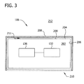
- Fig. 3 is a sectional schematic view of nacelle 106. While Fig. 3 only illustrates gearbox 136 and generator 132 positioned within nacelle 106, this is for clarity only. As shown in Fig. 2 , for example, any suitable component may be housed and/or positioned within nacelle 106.
- nacelle 106 includes an outer shell 200 that defines an inner cavity 202. More specifically, outer shell 200 includes an exterior surface 204 and an interior surface 206 that defines inner cavity 202. Gearbox 136, generator 132, and/or any suitable component of wind turbine 100 (shown in Fig. 1 ) is positioned within inner cavity 202.
- At least one insulative covering 208 is disposed upon and/or positioned adjacent to or about at least a portion of exterior surface 204 of outer shell 200.
- Insulative covering 208 is configured to insulate inner cavity 202 and/or reduce a temperature fluctuation within inner cavity 202.
- insulative covering 208 is disposed upon and/or positioned adjacent to or about substantially all portions of exterior surface 204 except a bottom portion 210.
- insulative covering 208 substantially covers, coats, and/or encloses exterior surface 204.
- insulative covering 208 is disposed upon and/or positioned adjacent to or about substantially all portions of exterior surface 204 including bottom portion 210.
- the terms "insulate” and "insulative" refer to providing or configuring a material or component to prevent or reduce a transfer of heat.
- insulative covering 208 is positioned adjacent to exterior surface 204 such that a gap 211 is defined between insulative covering 208 and exterior surface 204.
- gap 211 is a vacuum such that air and other gases or materials are substantially absent from gap 211.
- gap 211 may be filled with air or other gases, with an insulative material, and/or with any suitable material or composition. As such, gap 211 provides additional insulation to insulative covering 208 and/or to nacelle 106.
- insulative covering 208 includes one or more reflective films or coatings, ceramic layers, paints and/or lacquers.
- insulative covering 208 may include a heat reflecting film such as an aluminum foil, or any suitable material or composition. Insulative covering 208 reflects at least a portion of solar radiation that impacts exterior surface 204 and/or insulative covering 208. As such, insulative covering 208 reduces an amount of solar radiation and/or heat absorbed by nacelle 106, thus reducing a temperature and/or a fluctuation of the temperature inside inner cavity 202.
- insulative covering 208 may include a shield or another suitable structure coupled to nacelle 106 that reflects solar radiation and/or provides shade to nacelle 106.
- insulative covering 208 includes at least one thermochromic and/or any other suitable coating that changes color and/or reflectiveness based on an ambient temperature of an external environment 212 proximate to nacelle 106 and/or an ambient temperature within inner cavity 202.
- insulative covering 208 may include, without limitation, one or more thermochromic crystals embodied within a substrate or other medium, one or more thermochromic dyes or capsules, such as a leuco dye, embodied within a medium, and/or any suitable thermochromic material.
- the coating has a predetermined color at a predetermined temperature threshold or value.
- the coating becomes lighter in color if the ambient temperature increases above the temperature threshold, and the coating becomes darker in color if the ambient temperature decreases below the temperature threshold.
- the color becomes lighter due to a higher ambient temperature, more solar radiation is reflected from outer shell 200, and nacelle 106 absorbs less heat from the solar radiation.
- insulative covering 208 exhibits an increased resistance to heat absorption from solar radiation.
- the color becomes darker due to a lower ambient temperature, less solar radiation is reflected by outer shell 200, and nacelle 106 absorbs more heat from the solar radiation.
- insulative covering 208 exhibits an increased resistance to heat loss due to the increased absorption of solar radiation.
- insulative covering 208 increases a resistance to temperature fluctuations within inner cavity 202 as an ambient temperature progressively increases above and/or decreases below a temperature threshold.
- Fig. 4 illustrates a sectional schematic view of an alternative nacelle 300 suitable for use with wind turbine 100 (shown in Fig. 1 ). Except as described herein, nacelle 300 is substantially similar to nacelle 106 (shown in Fig. 3 ), and similar components are labeled with the same reference numerals.
- at least two insulative coverings 302, such as a first or inner covering 304 and a second or outer covering 306, are disposed upon and/or positioned adjacent to or about exterior surface 204 of outer shell 200.
- Inner covering 304 is disposed upon and/or positioned adjacent to or about exterior surface 204 to substantially cover, coat, and/or enclose exterior surface 204.
- inner covering 304 covers, coats, and/or encloses substantially all of exterior surface 204 except bottom portion 210
- outer covering 306 is disposed upon and/or positioned adjacent to or about inner covering 304 to substantially cover, coat, and/or enclose inner covering 304.
- inner covering 304 is positioned adjacent to exterior surface 204 such that an inner gap 308 is defined between inner covering 304 and exterior surface 204.
- outer covering 306 is positioned adjacent to inner covering 304 such that an outer gap 310 is defined between outer covering 306 and inner covering 304.
- inner gap 308 and outer gap 310 are vacuums such that air and other gases or materials are substantially absent from inner gap 308 and outer gap 310.
- inner gap 308 and/or outer gap 310 may be filled with air or other gases, with an insulative material, and/or with any suitable material or composition. As such, inner gap 308 and outer gap 310 provide additional insulation to inner covering 304, to outer covering 306, and/or to nacelle 106.
- inner covering 304 is reflective, and may include a metallic foil, a reflective paint or lacquer, a ceramic layer, and/or another suitable reflective material or composition.
- Outer covering 306 includes a suitable material or composition, such as a thermotropic coating, a thermochromic semiconductor coating, and/or any suitable material or coating that changes transparency based on an ambient temperature of external environment 212 and/or an ambient temperature within inner cavity 202.
- outer covering 306 may include, without limitation, one or more thermotropic crystals embodied within a substrate or other medium, a vanadium dioxide-based coating, and/or any suitable coating.
- outer covering 306 has a predetermined transparency at a predetermined temperature threshold or value. Outer covering 306 becomes more transparent if the ambient temperature increases above the temperature threshold, and outer covering 306 becomes less transparent (i.e., more opaque) if the ambient temperature decreases below the temperature threshold. As outer covering 306 becomes more transparent due to a higher ambient temperature, more solar radiation is passed through outer covering 306 and is reflected away from nacelle 300 by inner covering 304 such that nacelle 300 absorbs less heat from the solar radiation. As such, as the ambient temperature increases, inner covering 304 and outer covering 306 exhibit an increased resistance to heat absorption from solar radiation.
- outer covering 306 becomes more opaque due to a lower ambient temperature, less solar radiation is passed through outer covering 306 and reflected by inner covering 304. Rather, more solar radiation is absorbed by outer covering 306, and nacelle 300 absorbs more heat from the solar radiation. As such, as the ambient temperature decreases, inner covering 304 and outer covering 306 exhibit an increased resistance to heat loss due to the increased absorption of solar radiation. In other words, inner covering 304 and outer covering 306 increase a resistance to temperature fluctuations within inner cavity 202 as an ambient temperature progressively increases above and/or decreases below a temperature threshold.
- insulative covering 208, inner covering 304, and/or outer covering 306 may be disposed upon and/or positioned adjacent to or about exterior surface 204 of nacelle 106 and/or nacelle 300
- insulative covering 208, inner covering 304, and/or outer covering 306 may be disposed upon and/or positioned adjacent to or about any suitable surface of wind turbine 100.
- insulative covering 208, inner covering 304, and/or outer covering 306 may be disposed upon and/or positioned adjacent to or about, without limitation, one or more suitable surfaces of tower 102, rotor 108, hub 110, and/or rotor blades 112.
- existing wind turbines may be retrofitted to include insulative covering 208, inner covering 304, and/or outer covering 306 to reduce temperature fluctuations as described herein.
- insulative covering 208, inner covering 304, and/or outer covering 306 are embodied within one or more lacquers, paints, varnishes, and/or any other suitable coating.
- the coating is applied to exterior surface 204 by spraying, painting, and/or by any suitable application.
- insulative covering 208, inner covering 304, and/or outer covering 306 are embodied in a laminate, a layer of metal or alloy, a substrate, and/or any other suitable material that is adhesively coupled, sprayed, painted, and/or disposed upon and/or positioned adjacent to or about nacelle 106 and/or nacelle 300 by any other suitable method.
- Fig. 5 illustrates a method 400 of assembling a wind turbine, such as wind turbine 100 (shown in Fig. 1 ).
- a nacelle is coupled 402 to a tower.
- the nacelle includes an outer shell that has an exterior surface and an interior surface that defines an inner cavity.
- At least one insulative covering is disposed upon or positioned 404 adjacent to or about the exterior surface of the outer shell. The at least one insulative covering is configured to reduce a temperature fluctuation within the inner cavity as described herein.
- the insulative covering includes a reflective coating that is disposed upon and/or positioned 404 adjacent to or about the exterior surface of the outer shell. Additionally or alternatively, the insulative covering includes a coating that is disposed upon and/or positioned 404 adjacent to or about the exterior surface, and the coating is configured to change colors based on an ambient temperature. In yet another embodiment, the insulative covering includes an inner covering that is disposed upon and/or positioned 404 adjacent to or about an exterior surface of the outer shell, and an outer covering that is disposed upon and/or positioned 404 adjacent to or about the inner covering. In a particular embodiment, a reflective inner covering is disposed upon and/or positioned 404 adjacent to or about an exterior surface of the outer shell. An outer covering is disposed upon and/or positioned 404 adjacent to or about the inner covering. The outer covering is substantially transparent when an ambient temperature is above a temperature threshold and is substantially opaque when the ambient temperature is below the temperature threshold.
- the embodiments described herein provide a cost-effective and efficient insulative covering for controlling temperatures within a wind turbine.
- the insulative covering is disposed upon and/or positioned adjacent to or about one or more surfaces of a nacelle or to any other suitable surface of the wind turbine.
- the insulative covering enables the wind turbine to substantially reflect solar radiation when an ambient temperature is above a temperature threshold, and to substantially absorb solar radiation when the ambient temperature is below the temperature threshold.
- the insulative covering reflects an increasing amount of solar radiation.
- the insulative covering absorbs an increasing amount of solar radiation.
- the insulative covering reduces a temperature fluctuation within the nacelle.
- the insulative covering reduces an amount of energy required to heat and/or cool the nacelle.
- Exemplary embodiments of a wind turbine, a nacelle, and a method of assembling a wind turbine are described above in detail.
- the wind turbine, nacelle, and method are not limited to the specific embodiments described herein, but rather, components of the wind turbine and/or the nacelle and/or steps of the method may be utilized independently and separately from other components and/or steps described herein.
- the nacelle and method may also be used in combination with other power systems and methods, and are not limited to practice with only the wind turbine system as described herein. Rather, the exemplary embodiment can be implemented and utilized in connection with many other wind turbine or power system applications.
Landscapes
- Engineering & Computer Science (AREA)
- Life Sciences & Earth Sciences (AREA)
- Sustainable Development (AREA)
- Sustainable Energy (AREA)
- Chemical & Material Sciences (AREA)
- Combustion & Propulsion (AREA)
- Mechanical Engineering (AREA)
- General Engineering & Computer Science (AREA)
- Physics & Mathematics (AREA)
- Thermal Sciences (AREA)
- Wind Motors (AREA)
Applications Claiming Priority (1)
| Application Number | Priority Date | Filing Date | Title |
|---|---|---|---|
| US12/763,829 US20110133472A1 (en) | 2010-04-20 | 2010-04-20 | Wind Turbine, Nacelle, And Method Of Assembling Wind Turbine |
Publications (1)
| Publication Number | Publication Date |
|---|---|
| EP2381104A2 true EP2381104A2 (fr) | 2011-10-26 |
Family
ID=44069916
Family Applications (1)
| Application Number | Title | Priority Date | Filing Date |
|---|---|---|---|
| EP11162299A Withdrawn EP2381104A2 (fr) | 2010-04-20 | 2011-04-13 | Eolienne, nacelle et procédé de fabrication d'une telle éolienne |
Country Status (3)
| Country | Link |
|---|---|
| US (1) | US20110133472A1 (fr) |
| EP (1) | EP2381104A2 (fr) |
| CN (1) | CN102235321A (fr) |
Families Citing this family (7)
| Publication number | Priority date | Publication date | Assignee | Title |
|---|---|---|---|---|
| US8203230B2 (en) * | 2010-06-29 | 2012-06-19 | General Electric Company | Yaw bearing system |
| JP5463218B2 (ja) * | 2010-06-30 | 2014-04-09 | 三菱重工業株式会社 | 風力発電装置 |
| DE102011087161A1 (de) * | 2011-11-26 | 2013-05-29 | Repower Systems Se | Schutzhüllensatz und Verfahren zum Verpacken eines Großbauteils |
| US20130183162A1 (en) * | 2012-01-17 | 2013-07-18 | General Electric Company | Nacelle for wind turbine |
| US9800198B2 (en) * | 2014-05-23 | 2017-10-24 | Rizwan Shoukat | Automatic intelligent hybrid electricity generating device |
| DE102017004291A1 (de) * | 2017-05-04 | 2018-11-08 | Senvion Gmbh | Einhausung für eine Gondel einer Windenergieanlage |
| EP4125191A1 (fr) * | 2021-07-28 | 2023-02-01 | General Electric Renovables España S.L. | Refroidissement d'éléments actifs de machines électriques |
Family Cites Families (38)
| Publication number | Priority date | Publication date | Assignee | Title |
|---|---|---|---|---|
| US2540331A (en) * | 1945-06-18 | 1951-02-06 | Rudolf F Hlavaty | Insulation |
| US4642970A (en) * | 1984-10-25 | 1987-02-17 | William Bane | Reusable insulated box and method of manufacture |
| US4730748A (en) * | 1986-03-11 | 1988-03-15 | William Bane | Reusable insulated box |
| JPH0736719Y2 (ja) * | 1989-10-14 | 1995-08-23 | パイロットインキ株式会社 | 色彩記憶玩具セット |
| JPH0665568A (ja) * | 1992-08-19 | 1994-03-08 | Sakura Color Prod Corp | 熱変色性組成物 |
| JP3134108B2 (ja) * | 1992-10-26 | 2001-02-13 | パイロットインキ株式会社 | 熱変色性遮光性組成物及びこれを用いた積層体及び前記積層体を用いた内部隠顕立体物 |
| JP3306607B2 (ja) * | 1994-03-25 | 2002-07-24 | パイロットインキ株式会社 | 熱変色性遮光−透光性組成物及びこれを用いた積層体及び前記積層体を用いた内部隠顕立体物 |
| JP3845128B2 (ja) * | 1995-06-07 | 2006-11-15 | パイロットインキ株式会社 | 温度依存性色彩記憶性樹脂組成物及びこれを用いた積層体 |
| US5989135A (en) * | 1997-04-28 | 1999-11-23 | Night & Day Golf, Inc. | Luminescent golf ball |
| DE19941295A1 (de) * | 1999-08-31 | 2001-03-01 | Giesecke & Devrient Gmbh | Sicherheitselement |
| US6780127B2 (en) * | 2001-12-06 | 2004-08-24 | Callaway Golf Company | Golf ball with temperature indicator |
| US6706218B2 (en) * | 2000-01-11 | 2004-03-16 | The Board Of Governors For Higher Education, State Of Rhode Island And Providence Plantations | Thermochromic polymers for rapid visual assessment of temperature |
| US6352788B1 (en) * | 2000-02-22 | 2002-03-05 | General Electric Company | Thermal barrier coating |
| JP3910877B2 (ja) * | 2001-11-22 | 2007-04-25 | パイロットインキ株式会社 | 感温変色性複合繊維 |
| AU2003209053A1 (en) * | 2002-02-06 | 2003-09-02 | University Of Akron | Temperature indicator using thermochromic materials |
| ITTO20020908A1 (it) * | 2002-10-17 | 2004-04-18 | Lorenzo Battisti | Sistema antighiaccio per impianti eolici. |
| KR100572373B1 (ko) * | 2003-06-27 | 2006-04-24 | 주식회사 팬텀 | 열변색 골프공 |
| JP2007277790A (ja) * | 2006-04-07 | 2007-10-25 | Jae Woo Yang | 熱色性物質層を備えたウォールペーパー及びその製造方法 |
| US20080166563A1 (en) * | 2007-01-04 | 2008-07-10 | Goodrich Corporation | Electrothermal heater made from thermally conducting electrically insulating polymer material |
| ES2470615T3 (es) * | 2007-01-31 | 2014-06-24 | Vestas Wind Systems A/S | Convertidor de energía e�lica con deshumidificador |
| US7656055B2 (en) * | 2007-04-12 | 2010-02-02 | Rosalia Torres | Hydro-wind power generating turbine system and retrofitting method |
| US20090094981A1 (en) * | 2007-10-12 | 2009-04-16 | General Electric Company | Wind turbine geothermal heating and cooling system |
| US7901798B2 (en) * | 2007-12-18 | 2011-03-08 | General Electric Company | Wetting resistant materials and articles made therewith |
| US20090232659A1 (en) * | 2008-03-11 | 2009-09-17 | Joris Schiffer | Concrete to fabricate the nacelle of a wind turbine |
| US7815728B2 (en) * | 2008-05-02 | 2010-10-19 | L. M. Scofield Company | High SRI cementitious systems for colored concrete |
| ES2377669T3 (es) * | 2008-07-02 | 2012-03-29 | Siemens Aktiengesellschaft | Pala de turbina eólica con receptor de rayos y método para proteger la superficie de una pala de turbina eólica |
| WO2010080888A1 (fr) * | 2009-01-08 | 2010-07-15 | Jetboil, Inc. | Manchon isolant indiquant la température pour récipient de cuisson |
| EP2233450A1 (fr) * | 2009-03-27 | 2010-09-29 | Alstom Technology Ltd | Système de protection thermique multicouches et utilisation d' un tel |
| US8270060B2 (en) * | 2009-09-25 | 2012-09-18 | Samsung Sdi Co., Ltd. | Infrared ray transmittance controlling panel including color modifying layer |
| US8422113B2 (en) * | 2009-10-01 | 2013-04-16 | Samsung Sdi Co., Ltd. | Panel including thermochromic layer |
| US8047200B1 (en) * | 2009-11-19 | 2011-11-01 | Flaherty B Michael | Hybrid solar heating system |
| KR101127607B1 (ko) * | 2009-11-20 | 2012-03-22 | 삼성에스디아이 주식회사 | 전기 전도층이 포함된 써모크로믹 유리 |
| US9222015B2 (en) * | 2009-11-24 | 2015-12-29 | Swift River Properties, Llc | Thermochromic coating and method of manufacturing thereof |
| KR101137373B1 (ko) * | 2010-01-07 | 2012-04-20 | 삼성에스디아이 주식회사 | 스마트 창호 |
| US8227755B2 (en) * | 2010-04-28 | 2012-07-24 | L-3 Communications Corporation | Pixel-level optically transitioning filter elements for detector devices |
| US8513605B2 (en) * | 2010-04-28 | 2013-08-20 | L-3 Communications Corporation | Optically transitioning thermal detector structures |
| US8610070B2 (en) * | 2010-04-28 | 2013-12-17 | L-3 Communications Corporation | Pixel-level optical elements for uncooled infrared detector devices |
| US20110297358A1 (en) * | 2010-06-07 | 2011-12-08 | The Boeing Company | Nano-coating thermal barrier and method for making the same |
-
2010
- 2010-04-20 US US12/763,829 patent/US20110133472A1/en not_active Abandoned
-
2011
- 2011-04-13 EP EP11162299A patent/EP2381104A2/fr not_active Withdrawn
- 2011-04-19 CN CN2011101079267A patent/CN102235321A/zh active Pending
Non-Patent Citations (1)
| Title |
|---|
| None |
Also Published As
| Publication number | Publication date |
|---|---|
| CN102235321A (zh) | 2011-11-09 |
| US20110133472A1 (en) | 2011-06-09 |
Similar Documents
| Publication | Publication Date | Title |
|---|---|---|
| EP2381104A2 (fr) | Eolienne, nacelle et procédé de fabrication d'une telle éolienne | |
| Schubel et al. | Wind turbine blade design review | |
| EP1612412B1 (fr) | Commande pour éolienne en cas de tempête | |
| EP2252791B1 (fr) | Structure de pale rétractable à bord de fuite fendu | |
| EP2405133B1 (fr) | Parc éolien et procédé pour contrôler la production d'énergie d'une éolienne dans un parc éolien | |
| US8794903B2 (en) | Shrouded wind turbine system with yaw control | |
| US7312537B1 (en) | Methods and apparatus for supplying and/or absorbing reactive power | |
| US7750490B2 (en) | Method and system for extracting inertial energy from a wind turbine | |
| US20090148285A1 (en) | Multi-section wind turbine rotor blades and wind turbines incorporating same | |
| US8303249B2 (en) | Wind turbine and method for optimizing energy production therein | |
| EP2267298A2 (fr) | Pale d'éolienne à ailettes rotatives à son extrémité | |
| US20130045105A1 (en) | Wind turbine blade and method of protecting the same | |
| EP2657518B1 (fr) | Procédé et système d'exploitation d'une éolienne dans un mode d'opération avec réduction de bruit | |
| EP2719893B1 (fr) | Procédé de fonctionnement d'une éolienne à vitesse variable | |
| EP2128437A2 (fr) | Procédé d'augmentation de la capture d'énergie dans une éolienne | |
| US7235895B2 (en) | Method and apparatus for gravity induced thermal energy dissipation | |
| US20140017080A1 (en) | Wind turbine, wind farm and method for generating power | |
| EP2436924A1 (fr) | Appareil pour une éolienne | |
| CA2892050C (fr) | Rotor de turbine eolienne et ses procedes d'assemblage | |
| EP3964706A1 (fr) | Procédé de fonctionnement d'une éolienne, procédé de conception d'une éolienne et éolienne | |
| JP5517786B2 (ja) | 風力発電装置 | |
| WO2017190748A1 (fr) | Chauffage électrothermique amélioré | |
| JP2023513447A (ja) | 調整可能なブレードを有する抗力兼揚力ベースの風力タービンシステム | |
| TWI730337B (zh) | 風力發電裝置的控制方法 | |
| Ashley | Turbines catch their second wind |
Legal Events
| Date | Code | Title | Description |
|---|---|---|---|
| AK | Designated contracting states |
Kind code of ref document: A2 Designated state(s): AL AT BE BG CH CY CZ DE DK EE ES FI FR GB GR HR HU IE IS IT LI LT LU LV MC MK MT NL NO PL PT RO RS SE SI SK SM TR |
|
| AX | Request for extension of the european patent |
Extension state: BA ME |
|
| PUAI | Public reference made under article 153(3) epc to a published international application that has entered the european phase |
Free format text: ORIGINAL CODE: 0009012 |
|
| STAA | Information on the status of an ep patent application or granted ep patent |
Free format text: STATUS: THE APPLICATION IS DEEMED TO BE WITHDRAWN |
|
| 18D | Application deemed to be withdrawn |
Effective date: 20131101 |