EP2128437A2 - Procédé d'augmentation de la capture d'énergie dans une éolienne - Google Patents
Procédé d'augmentation de la capture d'énergie dans une éolienne Download PDFInfo
- Publication number
- EP2128437A2 EP2128437A2 EP09160614A EP09160614A EP2128437A2 EP 2128437 A2 EP2128437 A2 EP 2128437A2 EP 09160614 A EP09160614 A EP 09160614A EP 09160614 A EP09160614 A EP 09160614A EP 2128437 A2 EP2128437 A2 EP 2128437A2
- Authority
- EP
- European Patent Office
- Prior art keywords
- wind turbine
- set point
- control system
- rotational speed
- wind
- Prior art date
- Legal status (The legal status is an assumption and is not a legal conclusion. Google has not performed a legal analysis and makes no representation as to the accuracy of the status listed.)
- Granted
Links
- 238000000034 method Methods 0.000 title description 32
- 230000004044 response Effects 0.000 claims abstract description 22
- 238000012544 monitoring process Methods 0.000 claims description 12
- 239000003570 air Substances 0.000 description 26
- 239000011295 pitch Substances 0.000 description 8
- 230000007423 decrease Effects 0.000 description 7
- 238000013461 design Methods 0.000 description 6
- 238000010586 diagram Methods 0.000 description 6
- 230000008569 process Effects 0.000 description 6
- 230000007613 environmental effect Effects 0.000 description 5
- 238000004519 manufacturing process Methods 0.000 description 3
- 230000004913 activation Effects 0.000 description 2
- 238000001816 cooling Methods 0.000 description 2
- 230000002349 favourable effect Effects 0.000 description 2
- 230000006870 function Effects 0.000 description 2
- 230000004048 modification Effects 0.000 description 2
- 238000012986 modification Methods 0.000 description 2
- 238000004088 simulation Methods 0.000 description 2
- 230000003068 static effect Effects 0.000 description 2
- 230000002411 adverse Effects 0.000 description 1
- 239000012080 ambient air Substances 0.000 description 1
- 230000008901 benefit Effects 0.000 description 1
- 230000033228 biological regulation Effects 0.000 description 1
- 238000004364 calculation method Methods 0.000 description 1
- 230000008859 change Effects 0.000 description 1
- 230000008878 coupling Effects 0.000 description 1
- 238000010168 coupling process Methods 0.000 description 1
- 238000005859 coupling reaction Methods 0.000 description 1
- 238000006073 displacement reaction Methods 0.000 description 1
- 230000009977 dual effect Effects 0.000 description 1
- 230000006698 induction Effects 0.000 description 1
- 239000000463 material Substances 0.000 description 1
- 230000007246 mechanism Effects 0.000 description 1
- 230000003287 optical effect Effects 0.000 description 1
- 230000009467 reduction Effects 0.000 description 1
- 238000012546 transfer Methods 0.000 description 1
- 238000004804 winding Methods 0.000 description 1
Images

Classifications
-
- F—MECHANICAL ENGINEERING; LIGHTING; HEATING; WEAPONS; BLASTING
- F03—MACHINES OR ENGINES FOR LIQUIDS; WIND, SPRING, OR WEIGHT MOTORS; PRODUCING MECHANICAL POWER OR A REACTIVE PROPULSIVE THRUST, NOT OTHERWISE PROVIDED FOR
- F03D—WIND MOTORS
- F03D7/00—Controlling wind motors
- F03D7/02—Controlling wind motors the wind motors having rotation axis substantially parallel to the air flow entering the rotor
- F03D7/04—Automatic control; Regulation
- F03D7/042—Automatic control; Regulation by means of an electrical or electronic controller
- F03D7/043—Automatic control; Regulation by means of an electrical or electronic controller characterised by the type of control logic
- F03D7/046—Automatic control; Regulation by means of an electrical or electronic controller characterised by the type of control logic with learning or adaptive control, e.g. self-tuning, fuzzy logic or neural network
-
- F—MECHANICAL ENGINEERING; LIGHTING; HEATING; WEAPONS; BLASTING
- F03—MACHINES OR ENGINES FOR LIQUIDS; WIND, SPRING, OR WEIGHT MOTORS; PRODUCING MECHANICAL POWER OR A REACTIVE PROPULSIVE THRUST, NOT OTHERWISE PROVIDED FOR
- F03D—WIND MOTORS
- F03D7/00—Controlling wind motors
- F03D7/02—Controlling wind motors the wind motors having rotation axis substantially parallel to the air flow entering the rotor
- F03D7/0276—Controlling wind motors the wind motors having rotation axis substantially parallel to the air flow entering the rotor controlling rotor speed, e.g. variable speed
-
- F—MECHANICAL ENGINEERING; LIGHTING; HEATING; WEAPONS; BLASTING
- F05—INDEXING SCHEMES RELATING TO ENGINES OR PUMPS IN VARIOUS SUBCLASSES OF CLASSES F01-F04
- F05B—INDEXING SCHEME RELATING TO WIND, SPRING, WEIGHT, INERTIA OR LIKE MOTORS, TO MACHINES OR ENGINES FOR LIQUIDS COVERED BY SUBCLASSES F03B, F03D AND F03G
- F05B2270/00—Control
- F05B2270/10—Purpose of the control system
- F05B2270/103—Purpose of the control system to affect the output of the engine
- F05B2270/1033—Power (if explicitly mentioned)
-
- F—MECHANICAL ENGINEERING; LIGHTING; HEATING; WEAPONS; BLASTING
- F05—INDEXING SCHEMES RELATING TO ENGINES OR PUMPS IN VARIOUS SUBCLASSES OF CLASSES F01-F04
- F05B—INDEXING SCHEME RELATING TO WIND, SPRING, WEIGHT, INERTIA OR LIKE MOTORS, TO MACHINES OR ENGINES FOR LIQUIDS COVERED BY SUBCLASSES F03B, F03D AND F03G
- F05B2270/00—Control
- F05B2270/30—Control parameters, e.g. input parameters
- F05B2270/327—Rotor or generator speeds
-
- Y—GENERAL TAGGING OF NEW TECHNOLOGICAL DEVELOPMENTS; GENERAL TAGGING OF CROSS-SECTIONAL TECHNOLOGIES SPANNING OVER SEVERAL SECTIONS OF THE IPC; TECHNICAL SUBJECTS COVERED BY FORMER USPC CROSS-REFERENCE ART COLLECTIONS [XRACs] AND DIGESTS
- Y02—TECHNOLOGIES OR APPLICATIONS FOR MITIGATION OR ADAPTATION AGAINST CLIMATE CHANGE
- Y02E—REDUCTION OF GREENHOUSE GAS [GHG] EMISSIONS, RELATED TO ENERGY GENERATION, TRANSMISSION OR DISTRIBUTION
- Y02E10/00—Energy generation through renewable energy sources
- Y02E10/70—Wind energy
- Y02E10/72—Wind turbines with rotation axis in wind direction
Definitions
- the present invention is directed generally to wind turbines, and more particularly to a method for increasing energy capture.
- the present invention is directed to controlling the speed of rotation of the wind turbine blades to increase the amount of energy capture.
- a wind turbine includes a rotor having multiple blades.
- the rotor is mounted to a housing or nacelle, which is positioned on top of a truss or tubular tower.
- Utility grade wind turbines i.e., wind turbines designed to provide electrical power to a utility grid
- the wind turbines are typically mounted on towers that are at least 60 meters in height. Blades on these rotors transform wind energy into a rotational torque or force that drives one or more generators that may be rotationally coupled to the rotor through a gearbox.
- the gearbox steps up the inherently low rotational speed of the turbine rotor for the generator to efficiently convert mechanical energy to electrical energy, which is fed into a utility grid.
- the initial design of a wind turbine controls may use standards such as IEC 61400.
- the standardized environmental conditions such as average wind speed, turbulence intensity or air density are the basis for the design.
- the IEC standard defines a small number of different "type classes" that categorize a wind turbine design for broader range of environmental conditions. As such, the standard controller configuration fails to address all of the types of site locations on which the wind turbine may be installed.
- many wind turbine sites include more favorable environmental conditions that give less stress on the actual wind turbine than the design conditions. At these sites, it is possible to use this application to increase the wind turbine performance, using a higher average rotor speed, without damaging wind turbine components.
- One aspect of the present invention includes a method for operating a wind turbine.
- the method includes providing a wind turbine having a variable speed control system, the control system having an initial rotational speed set point. At least two operational parameters are obtained from one or more sensors. An adjusted rotational speed set point greater than the initial rotational speed set point is determined in response to the operational parameter.
- the control system is configured with the adjusted rotational speed set point.
- the control system has an initial rotational speed set point.
- the wind turbine also includes at least one sensor arranged and disposed to obtain at least two operational parameters.
- the control system is selectively configured with an adjusted rotational speed set point greater than the initial rotational speed set point in response to the operational parameter.
- Still another aspect of the present invention includes a wind plant having a plurality of wind turbines.
- the wind turbines each include a variable speed control system.
- the control system has an initial rotational speed set point.
- At least one sensor arranged and disposed to obtain at least two operational parameters.
- the control system is selectively configured with an adjusted rotational speed set point greater than the initial rotational speed set point in response to the operational parameter.
- the wind plant further includes a central monitoring station.
- the central monitoring station is configured to selectively permit adjustment of the control system in response to an external requirement.
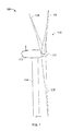
- the wind turbine 100 includes a nacelle 102 mounted atop a tall tower 104, only a portion of which is shown in FIG. 1 .
- Wind turbine 100 also comprises a wind turbine rotor 106 that includes one or more rotor blades 108 attached to a rotating hub 110.
- wind turbine 100 illustrated in FIG. 1 includes three rotor blades 108, there are no specific limits on the number of rotor blades 108 required by the present invention.
- the height of tower 104 is selected based upon factors and conditions known in the art.
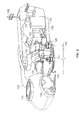
- various components are housed in nacelle 102 atop tower 104.
- One or more microcontrollers or other control components are housed within control panel 112.
- the microcontrollers include hardware and software configured to provide a control system providing overall system monitoring and control, including pitch and speed regulation, high-speed shaft and yaw brake application, yaw and pump motor application and fault monitoring.
- the control system may be a distributed control architecture not solely provided for by the control panel 112 as would be appreciated by one of ordinary skill in the art.
- the control system provides control signals to a variable blade pitch drive 114 to control the pitch of blades 108 ( FIG. 1 ) that drive hub 110 as a result of wind.
- the pitches of blades 108 are individually controlled by blade pitch drive 114.
- the drive train of the wind turbine includes a main rotor shaft 116 (also referred to as a "low speed shaft”) connected to hub 110 and supported by a main bearing 130 and, at an opposite end of shaft 116, to a gear box 118.
- Gear box 118 in some configurations, utilizes a dual path geometry to drive an enclosed high-speed shaft.
- the high-speed shaft (not shown in FIG. 2 ) is used to drive generator 120, which is mounted on mainframe 132.
- rotor torque is transmitted via coupling 122.
- Generator 120 may be of any suitable type, for example, a wound rotor induction generator.
- Yaw drive 124 and yaw deck 126 provide a yaw orientation system for wind turbine 100.
- Anemometry provides information for the yaw orientation system, including measured instantaneous wind direction and wind speed at the wind turbine. Anemometry may be provided by a wind vane 128.
- the yaw system is mounted on a flange provided atop tower 104.
- Embodiments of the present disclosure are not limited to the configuration shown in FIGs. 1 and 2 and may include any configuration of wind turbine 100 known in the art having a control system and rotational speed control.
- the wind turbine 100 may include more or less than three blades 108.
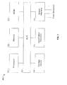
- an exemplary control system 300 for wind turbine 100 includes a bus 302 or other communications device to communicate information.
- Processor(s) 304 are coupled to bus 302 to process information, including information from sensors configured to measure displacements or moments.
- Control system 300 further includes random access memory (RAM) 306 and/or other storage device(s) 308.
- RAM 306 and storage device(s) 308 are coupled to bus 302 to store and transfer information and instructions to be executed by processor(s) 305.
- RAM 306 (and also storage device(s) 308, if required) can also be used to store temporary variables or other intermediate information during execution of instructions by processor(s) 305.
- Control system 300 can also include read only memory (ROM) and or other static storage device 310, which is coupled to bus 302 to store and provide static (i.e., non-changing) information and instructions to processor(s) 304.
- Input/output device(s) 312 can include any device known in the art to provide input data to control system 300 and to provide yaw control and pitch control outputs. Instructions are provided to memory from a storage device, such as magnetic disk, a read-only memory (ROM) integrated circuit, CD-ROM, DVD, via a remote connection that is either wired or wireless providing access to one or more electronically-accessible media, etc.
- ROM read-only memory
- DVD digital versatile discs
- Sensor interface 314 is an interface that allows control system 300 to communicate with one or more sensors.
- Sensor interface 314 can be or can comprise, for example, one or more analog-to-digital converters that convert analog signals into digital signals that can be used by processor(s) 304.
- the sensor interface includes signals from a rotor speed determining device and anemometry from wind vane 128.
- the present disclosure includes a method for increasing energy capture of a wind turbine by controllably adjusting the maximum or rated rotational speed set point in response to a measured operational value.
- “Rotational speed”, as utilized herein, is defined as the speed at which the blades rotate about the hub. The rotational speed may include the speed at which the low speed shaft 116 rotates or may be calculated from the speed of the high-speed shaft or at the generator 120.
- “Rated power”, as utilized herein, is defined as the power that the wind turbine generates at a maximum capacity, wherein the maximum capacity is determined by the control system.
- “Rated rotational speed”, as utilized herein is defined as the speed at which the rotor is permitted to rotate in continuous operations during full load operations. The rated rotational speed may correspond to the maximum power capacity, but may include wind turbine operation below the maximum power capacity.
- the controlled adjustment may include a feature installed on an existing wind turbine with no modification of the wind turbine components. During the period of time of increased maximum rotor speed set point, the wind turbine is able to run at a higher rated power and achieve a significantly higher energy production. In this embodiment, no components of the turbine need to be changed or added.
- the method includes operating a wind turbine having a variable speed control system.
- wind turbine control systems typically include sophisticated control systems and control programs.
- the control programs utilize wind turbine components to adjust various operational parameters within the wind turbine 100. For example, pitch blade angle and generator torque may be adjusted to vary the power output at the generator 120 and/or to adjust the rotational speed of the blades 108 in response to a wind speed.
- the wind turbine 100 will include a variable speed operational period (e.g., operation during shutdown and startup) and a constant speed operational period (e.g., during normal operating conditions or at maximum rated power operation).
- the control system includes an initial or rated rotational speed set point value.
- the initial rotational speed set point value corresponds to the designed maximum rotational speed at which the wind turbine is permitted to operate. While not so limited, the initial rotational speed set point value may be determined according to known design parameters or standards, such as international standards (e.g., IEC 61400). In the control configuration, the standardized environmental conditions such as average wind speed, turbulence intensity or air density for a theoretical average wind turbine site may form the basis for the design and configuration. White during normal operation (i.e., the constant speed operational period), the rotational speed is not permitted to exceed the maximum rotational speed set point. It is noted, however, that power output of the wind turbine 100 may vary at the maximum rotational speed by varying other parameters, such as torque.
- the method of various embodiments of the present disclosure includes a method wherein the initial rated rotational speed set point value is increased from the initial value in response to at least two operational parameters.
- the operational parameters are measured at one or mores sensors at the wind turbine 100, at a monitoring station for a wind turbine plant, or at a location corresponding to the wind turbine operation.
- the operational parameter are preferably selected from the group consisting of generator speed, power output, turbulence intensity (e.g., turbulence intensity measured as function of the standard deviation of the rotational speed), wind speed, wind direction (both in vertical and horizontal sense), wind shear, the combination of ambient temperature and air pressure, air density, component temperatures (e.g., generator windings, bearings, generator and gearbox cooling, gearbox oil, transformer, and/or converter), generator torque, current in generator rotor and stator, voltage in generator rotor and stator, power factor, tower top vibration, drive train vibrations, yaw position and combinations thereof. More preferably, the operational parameter is at least two parameters selected from the group consisting of an air turbulence intensity, air density, tower vibration, ambient temperature, wind turbine component temperature, yaw position and combinations thereof.
- turbulence intensity e.g., turbulence intensity measured as function of the standard deviation of the rotational speed
- wind speed wind direction (both in vertical and horizontal sense), wind shear
- the sensors for measuring the operational parameters may be any suitable sensors known in the art for measuring or sensing the operational parameter. Suitable sensors may include thermometers, thermocouples, thermistors, anemometers, pressure sensors, optical sensors, proximity sensors, encoders (e.g., encoder mounted on the individual components) or any other known sensor or sensor system.
- the sensors may be included at the wind turbine location or at a location remote from the wind turbine, such as at a remote monitoring system.
- the sensor may indirectly measure an operational parameter, such as by measuring a value that may be utilized to calculate an operational parameter.
- a plurality of sensors may be utilized to determine a single operational parameter.
- an adjusted, increased, rotational speed set point value is determined in response to the operational parameter.
- the amount of increase in rotational speed can be determined using any suitable model or calculation that is capable of determining a rotor speed that is greater than the initial rotational speed set point, and provides an adjusted rotor speed that is mechanically permitted by the wind turbine 100 and the conditions surrounding the wind turbine 100.
- the target rotational speed is a function of the standard deviation of the controlled rotational speed, which may be a measure of turbulence intensity.
- the increase in rotational speed set point value may be determined by the general relationship that as the annual average wind speed decreases, the mechanical loads on the wind turbine decrease, permitting an increase in rotational speed set point value.
- Combinations of two or more operational parameters are preferably utilized according to their respect relationships. For example, a lower ambient temperature and a higher air density are favorable for the cooling of the components, which results in lower mechanical loads on the wind turbine 100, permitting an increase in rotational speed set point value.
- a reduced power factor increases the electrical current and with that, the temperatures of components within the wind turbine 100, permitting an increase in rotational speed set point value.
- the temperature of some components of the wind turbine increases and other unfavorable component properties like voltage of the generator can increase.
- the new set point for the generator may be set, based on the parameters described above. For example, using the physical relationship of these parameters on turbine loads and power determines the new set point.
- a measured standard density of 1.225 with medium turbulence may result in a speed set point 6 % greater than the initial rotational speed set point.
- the measured density is 1.100 (i.e., lower than 1.225) adjust rotational speed set point will be set to 9% above the initial rotational speed set point.
- the inverse relationships of the above operational parameters to the value of increased rotational speed set point result in a reduction in the amount of increase or prevents an increase in the rotational speed set point value.
- the control system may only slightly increase the rotational speed set point value, or may not increase the rotational speed set point value.
- FIG. 4 shows a process flow diagram illustrating one embodiment of the present disclosure.
- a determination is made to whether controller speed control adjustment is activated, step 401. If the controller speed is not activated the controller maintains default settings, step 403.
- the default settings include a setting of the speed control to the initial rotational speed set point value.
- the determination in step 401 may include a switch, button, software determined option, or other mechanism that permits the selective activation of the speed control adjustment method.
- the speed control adjustment is activated, at least two operational parameters are obtained, step 405.
- the operational parameters are preferably obtained from sensors. Once the operational parameters are obtained, an adjusted rotational speed is determined in response to the operational parameters, step 407.
- the adjusted rotational speed is an adjusted rotational speed set point value for the control system that is greater than the initial or rated rotational speed set point value.
- the controller or control system is configured with the adjusted rotational speed set point, step 409.
- the control system permits the wind turbine to operate at the increased rotational speed set point value and the method repeats.
- a user interface is provided to provide the speed control activation, step 401.
- the interface may include, but is not limited to, the following: 1) an option to set time of day to operate in boost, 2) an option to set maximum boost allowed - up to a (e.g., extreme loads defined) limit, 3) an option to control the wind turbine remotely from a central control with plant power limits and plant power factors incorporated in the control provided by the central control.
- the interface is not so limited and may include other options or other features, as desired for wind turbine and wind turbine plant operation.
- the ability for the controller to adjust the rotational set point value can be activated by an external requirement.
- Suitable external requirements that may activate the ability for the controller to adjust the maximum rotor speed include, but are not limited to, electrical (e.g., power factor or overall rating) or environmental site properties (e.g.. wind speed, wind shear, turbulence).
- an estimate of the lifetime or change in the lifetime of the turbine e.g. calculated out of simulations of mechanical fatigue loads, based upon increased maximum rotor speeds may be communicated to a user, central monitoring station or other location.
- the external requirement may include electrical or site properties over the entire wind plant.
- a wind plant comprising a plurality of wind turbines may include an external requirement of a maximum plant power output (i.e., the total power produced by the entire wind plant), which when exceeded selectively prevents wind turbines from increasing the rotational speed set point value in excess of the initial or rated rotational speed set point value.
- a maximum plant power output i.e., the total power produced by the entire wind plant
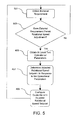
- FIG. 5 shows a process flow diagram illustrating another embodiment of the present disclosure.
- the embodiment shown in FIG. 5 includes obtaining an external requirement, step 501.
- a determination is made to whether the external requirement is satisfied, step 503. If the external requirement is not satisfied, the process is repeated and the rotational speed set point value is maintained at the initial rotational speed set point value.
- at least two operational parameters are obtained, step 405.
- the operational parameters are preferably obtained from sensors.
- an adjusted rotational speed is determined in response to the operational parameters, step 407.
- the adjusted rotational speed is an adjusted rotational speed set point value for the control system that is greater than the initial or rated rotational speed set point value.
- the controller or control system is configured with the adjusted rotational speed set point, step 409.
- the control system permits the wind turbine to operate at the increased rotational speed set point value and the method repeats.
- Example 1 includes results of simulations using the method of an embodiment of the present disclosure for annual energy production (AEP) in terms of percent increase for operation at rotational speed set points greater than the initial speed set point for varying wind speed averages (V avg ), see Table 1.
- the operational parameters are density and average wind speed.
- Table 1 EXAMPLE 1 V avg AEP Increase Density 1.225 AEP Increase Density 1.100 7.00 3.22% 4.54% 7.50 3.50% 5.00% 8.00 3.74% 5.41% 8.50 3.97% 5.78% 10.00 4.50% 6.62%
- the increase shown in Table 1 corresponds to an increase with respect to the AEP produced at the initial set point value or rated set point value of the wind turbine.
- the initial speed set point value or rated set point for the wind turbine corresponds to a 0% increase in AEP.
- Example 2 shows rotational speed set points value variations with respect to the operational parameters of air density and turbulence intensity (TI), see Table 2.
- Table 2 EXAMPLE 2 Air Density Turbulence Intensity Increase Of Set Point From Initial Speed Set Point 1.100 16% 9.70% 1.225 16% 6.25% 1.270 16% 3.00%
- the initial speed set point value or rated set point for the wind turbine corresponds to a 0% increase of set point from initial speed set point.
- Example 3 shows annual energy production (AEP) variations with respect to the operational parameters of wind velocity, air density and turbulence intensity, see Table 3.
- Table 3 EXAMPLE 3 V avg AEP Increase Density 1.225 High Turbulence AEP Increase Density 1.225 Medium Turbulence AEP Increase Density 1.225 Low Turbulence 7.00 2.8% 3.22% 3.85% 7.50 3.0% 3.5% 4.3% 8.00 3.1% 3.74% 4.71% 8.50 3.2% 3.97% 5.06% 10.00 3.3% 4.50% 5.83%
- the increase shown in Table 3 corresponds to an increase with respect to the AEP produced at the initial set point value or rated set point value of the wind turbine.
- the initial speed set point value or rated set point for the wind turbine corresponds to a 0% increase in AEP.
- Example 4 shows rotational speed set points value variations with respect to the operational parameters of air density and turbulence intensity, see Table 4.
- Table 4 EXAMPLE 4 Air Density Turbulence Intensity Increase Of Set Point From Original Speed Set Point 1.225 18% 3.00% 1.225 16% 6.25% 1.225 14% 7.80%
- the initial speed set point value or rated set point for the wind turbine corresponds to a 0% increase of set point from initial speed set point.
Applications Claiming Priority (1)
| Application Number | Priority Date | Filing Date | Title |
|---|---|---|---|
| US12/128,861 US8093737B2 (en) | 2008-05-29 | 2008-05-29 | Method for increasing energy capture in a wind turbine |
Publications (3)
| Publication Number | Publication Date |
|---|---|
| EP2128437A2 true EP2128437A2 (fr) | 2009-12-02 |
| EP2128437A3 EP2128437A3 (fr) | 2012-07-25 |
| EP2128437B1 EP2128437B1 (fr) | 2017-10-11 |
Family
ID=41066699
Family Applications (1)
| Application Number | Title | Priority Date | Filing Date |
|---|---|---|---|
| EP09160614.5A Revoked EP2128437B1 (fr) | 2008-05-29 | 2009-05-19 | Procédé d'augmentation de la capture d'énergie dans une éolienne |
Country Status (6)
| Country | Link |
|---|---|
| US (2) | US8093737B2 (fr) |
| EP (1) | EP2128437B1 (fr) |
| JP (1) | JP5491769B2 (fr) |
| CN (1) | CN101592118B (fr) |
| CA (1) | CA2666269C (fr) |
| DK (1) | DK2128437T3 (fr) |
Cited By (10)
| Publication number | Priority date | Publication date | Assignee | Title |
|---|---|---|---|---|
| WO2011157348A1 (fr) * | 2010-06-16 | 2011-12-22 | Robert Bosch Gmbh | Procédé et système de surveillance d'état pour éoliennes |
| FR2962498A1 (fr) * | 2010-07-07 | 2012-01-13 | Eolys Ressources Et En | Aerogenerateur a axe horizontal, comprenant un automate pour piloter un effacement progressif de la nacelle en fonction de la vitesse du vent. |
| WO2011157271A3 (fr) * | 2010-06-14 | 2012-05-18 | Vestas Wind Systems A/S | Procédé et unité de commande pour commander une éolienne en fonction d'une charge subie par l'éolienne |
| WO2012149984A1 (fr) | 2011-05-04 | 2012-11-08 | Siemens Aktiengesellschaft | Système et procédé pour faire fonctionner une éolienne au moyen d'une référence de vitesse adaptative |
| WO2014048583A1 (fr) | 2012-09-28 | 2014-04-03 | Siemens Aktiengesellschaft | Procédé et agencement permettant de commander une éolienne |
| EP2821637A1 (fr) * | 2013-06-26 | 2015-01-07 | General Electric Company | Système et procédé pour contrôler une éolienne |
| WO2020174007A1 (fr) * | 2019-02-26 | 2020-09-03 | Senvion Deutschland Gmbh | Procédé et système de commande d'une installation d'éoliennes |
| CN113027696A (zh) * | 2019-12-24 | 2021-06-25 | 新疆金风科技股份有限公司 | 液压变桨系统的故障诊断方法和装置 |
| EP3851669A1 (fr) * | 2020-01-16 | 2021-07-21 | General Electric Company | Systèmes et procédés de fonctionnement d'éoliennes utilisant des courbes de puissance améliorées |
| EP3910194A1 (fr) * | 2020-05-12 | 2021-11-17 | Siemens Gamesa Renewable Energy A/S | Agencement pour la commande d'éolienne |
Families Citing this family (51)
| Publication number | Priority date | Publication date | Assignee | Title |
|---|---|---|---|---|
| DE102007026995C5 (de) * | 2007-06-07 | 2017-03-30 | Senvion Gmbh | Drehzahlbestimmung |
| US8183707B2 (en) * | 2007-10-30 | 2012-05-22 | General Electric Company | Method of controlling a wind energy system and wind speed sensor free wind energy system |
| US8093737B2 (en) * | 2008-05-29 | 2012-01-10 | General Electric Company | Method for increasing energy capture in a wind turbine |
| WO2010000723A2 (fr) * | 2008-06-30 | 2010-01-07 | Vestas Wind Systems A/S | Procédé de commande d'une installation éolienne |
| US20110068577A1 (en) * | 2009-09-18 | 2011-03-24 | Hiwin Mikrosystem Corp. | Apparatus for providing overload protection for wind power generator and method thereof |
| DK201070274A (en) * | 2009-10-08 | 2011-04-09 | Vestas Wind Sys As | Control method for a wind turbine |
| DE102010001619A1 (de) * | 2010-02-05 | 2011-08-11 | Siemens Aktiengesellschaft, 80333 | Ständer einer permanenterregten rotierenden elektrischen Maschine |
| US8120194B2 (en) * | 2010-03-05 | 2012-02-21 | General Electric Company | System, device, and method for wind turbine load reduction in a cold weather environment |
| WO2011109611A1 (fr) * | 2010-03-05 | 2011-09-09 | Deka Products Limited Partnership | Appareil d'éolienne, systèmes et procédés associés |
| DK177434B1 (en) * | 2010-06-18 | 2013-05-21 | Vestas Wind Sys As | Method for controlling a wind turbine |
| EP2613047B1 (fr) * | 2010-08-31 | 2018-07-11 | Mitsubishi Heavy Industries, Ltd. | Méthode de conception d'un rotor d'éolienne, dispositif d'assistance à la conception d'un rotor d'éolienne et programme d'assistance à la conception d'un rotor d'éolienne |
| DE102010044433A1 (de) * | 2010-09-06 | 2012-03-08 | Nordex Energy Gmbh | Verfahren zur Drehzahlregelung einer Windenergieanlage |
| WO2012118549A1 (fr) | 2010-12-09 | 2012-09-07 | Northern Power Systems, Inc. | Systèmes pour la réduction de charge dans une tour d'un module d'énergie éolienne inactif, et procédés associés |
| DE102010054013A1 (de) * | 2010-12-10 | 2012-06-14 | Nordex Energy Gmbh | Verfahren zum Betrieb einer pitchgeregelten Windenergieanlage |
| US8169098B2 (en) * | 2010-12-22 | 2012-05-01 | General Electric Company | Wind turbine and operating same |
| US20110193344A1 (en) * | 2010-12-29 | 2011-08-11 | Vestas Wind Systems A/S | Control Network for Wind Turbine Park |
| EP2520795B1 (fr) | 2011-05-03 | 2022-07-06 | Siemens Gamesa Renewable Energy A/S | Procédé et module de calcul permettant de déterminer les signaux d'ajustement d'angle d'inclinaison d'une éolienne en fonction de la vitesse rotationnelle maximale |
| EP2565442A1 (fr) * | 2011-09-05 | 2013-03-06 | Siemens Aktiengesellschaft | Système et procédé de fonctionnement d'une éolienne utilisant des variables de référence adaptatives |
| DE102011101897A1 (de) * | 2011-05-18 | 2012-11-22 | Nordex Energy Gmbh | Verfahren zum Betreiben einer Windenergieanlage |
| ES2912102T3 (es) * | 2011-05-20 | 2022-05-24 | Insight Analytics Solutions Holdings Ltd | Determinación de daños y vida útil restante de maquinaria rotativa incluyendo trenes de transmisión, cajas de engranajes y generadores |
| ES2398027B1 (es) * | 2011-05-24 | 2014-09-05 | Gamesa Innovation & Technology, S.L. | Métodos y sistemas de control de aerogeneradores en condiciones de clima frio y baja altitud. |
| US9201410B2 (en) | 2011-12-23 | 2015-12-01 | General Electric Company | Methods and systems for optimizing farm-level metrics in a wind farm |
| CN103174587B (zh) * | 2011-12-26 | 2015-04-22 | 台达电子工业股份有限公司 | 风力发电系统及其控制方法 |
| EP2610484A1 (fr) * | 2011-12-26 | 2013-07-03 | Vestas Wind Systems A/S | Procédé de contrôle d'une éolienne |
| TWI494505B (zh) * | 2011-12-26 | 2015-08-01 | Delta Electronics Inc | 風力發電系統及其控制方法 |
| GB201200491D0 (en) * | 2012-01-12 | 2012-02-22 | Romax Technology Ltd | Method for operating a wind turbine generator |
| US9587628B2 (en) | 2012-01-17 | 2017-03-07 | General Electric Company | Method for operating a wind turbine |
| US8890349B1 (en) * | 2012-01-19 | 2014-11-18 | Northern Power Systems, Inc. | Load reduction system and method for a wind power unit |
| US9018787B2 (en) | 2012-04-24 | 2015-04-28 | General Electric Company | System and method of wind turbine control using a torque setpoint |
| US9624905B2 (en) | 2013-09-20 | 2017-04-18 | General Electric Company | System and method for preventing excessive loading on a wind turbine |
| US9683552B2 (en) * | 2014-03-06 | 2017-06-20 | General Electric Company | System and method for robust wind turbine operation |
| US9631606B2 (en) | 2014-04-14 | 2017-04-25 | General Electric Company | System and method for thrust-speed control of a wind turbine |
| CN105222742A (zh) * | 2014-05-26 | 2016-01-06 | 通用电气公司 | 浆距故障检测系统和方法 |
| JP6444740B2 (ja) * | 2014-05-29 | 2018-12-26 | 株式会社東芝 | 風力発電システムおよび風力発電方法 |
| US9926910B2 (en) * | 2015-03-13 | 2018-03-27 | General Electric Company | Wind turbine setpoint control |
| CN105134487B (zh) * | 2015-08-24 | 2017-11-14 | 南京理工大学 | 一种考虑湍流频率因素的风力机最大功率点跟踪控制方法 |
| JP6756489B2 (ja) * | 2016-02-17 | 2020-09-16 | 株式会社日立製作所 | 風力発電装置の制御方法 |
| DE102016110190A1 (de) * | 2016-06-02 | 2017-12-07 | Wobben Properties Gmbh | Verfahren zum Steuern einer Windenergieanlage und Windenergieanlage |
| CN106677985A (zh) * | 2016-12-13 | 2017-05-17 | 云南能投海装新能源设备有限公司 | 一种风力发电机组评估系统及其预测控制服务系统 |
| DE102016124703A1 (de) * | 2016-12-16 | 2018-06-21 | Wobben Properties Gmbh | Verfahren zum Betrieb einer Windenergieanlage sowie Einrichtung zum Steuern und/oder Regeln einer Windenergieanlage und entsprechende Windenergieanlage mit einem Rotor und einem über den Rotor angetriebenen Generator zur Erzeugung einer elektrischen Leistung |
| JP2018119427A (ja) | 2017-01-24 | 2018-08-02 | 株式会社日立製作所 | 風力発電システムまたは風力発電システムの運転方法 |
| JP2018178900A (ja) | 2017-04-18 | 2018-11-15 | 株式会社日立製作所 | 風力発電システム |
| US10697439B2 (en) | 2017-06-14 | 2020-06-30 | General Electric Company | Offset toggle method for wind turbine operation |
| US10634121B2 (en) | 2017-06-15 | 2020-04-28 | General Electric Company | Variable rated speed control in partial load operation of a wind turbine |
| CN109578203B (zh) * | 2017-09-28 | 2021-03-02 | 中车株洲电力机车研究所有限公司 | 风力发电机组极端工况下的主动降载控制方法及装置 |
| DE102018100727A1 (de) | 2018-01-15 | 2019-07-18 | Wobben Properties Gmbh | Verfahren zum Steuern einer Windenergieanlage und Windenergieanlage |
| DE102018100726A1 (de) * | 2018-01-15 | 2019-07-18 | Wobben Properties Gmbh | Windenergieanlage und Verfahren zum Steuern einer Windenergieanlage |
| DE102018113531A1 (de) * | 2018-06-06 | 2019-12-12 | Wobben Properties Gmbh | Verfahren zum Betreiben einer Windenergieanlage sowie Einrichtung zum Steuern und/oder Regeln einer Windenergieanlage und Windenergieanlage mit einem Rotor und einem über den Rotor angetriebenen Generator |
| WO2020078518A1 (fr) * | 2018-10-18 | 2020-04-23 | Vestas Wind Systems A/S | Modification de stratégie de commande permettant la commande d'une éolienne à l'aide d'une probabilité de charge et d'une limite de charge théorique |
| EP3909117B1 (fr) * | 2019-01-10 | 2022-11-23 | Vestas Wind Systems A/S | Améliorations concernant des générateurs électriques d'éoliennes |
| WO2020195691A1 (fr) | 2019-03-28 | 2020-10-01 | Ntn株式会社 | Système de surveillance d'état |
Citations (3)
| Publication number | Priority date | Publication date | Assignee | Title |
|---|---|---|---|---|
| US5289041A (en) * | 1991-09-19 | 1994-02-22 | U.S. Windpower, Inc. | Speed control system for a variable speed wind turbine |
| EP1429025A1 (fr) * | 2001-12-28 | 2004-06-16 | Mitsubishi Heavy Industries, Ltd. | Eolienne de type face au vent et procede de fonctionnement correspondant |
| US20050276696A1 (en) * | 2004-06-10 | 2005-12-15 | Lemieux David L | Methods and apparatus for rotor blade ice detection |
Family Cites Families (15)
| Publication number | Priority date | Publication date | Assignee | Title |
|---|---|---|---|---|
| US3665274A (en) * | 1970-05-05 | 1972-05-23 | Gen Electric | Reversible motor control having alternatively operative dual amplifiers and automatic response adjustment |
| DE3342583C2 (de) | 1983-11-25 | 1986-02-27 | Deutsche Forschungs- und Versuchsanstalt für Luft- und Raumfahrt e.V., 5300 Bonn | Verfahren zum Betrieb einer Windkraftanlage |
| US4703189A (en) * | 1985-11-18 | 1987-10-27 | United Technologies Corporation | Torque control for a variable speed wind turbine |
| DE19844258A1 (de) | 1998-09-26 | 2000-03-30 | Dewind Technik Gmbh | Windenergieanlage |
| ES2228121T3 (es) * | 1999-11-03 | 2005-04-01 | Vestas Wind Systems A/S | Procedimiento de control de la operacion de una turbina electrica y turbina electrica para usarse en dicho procedimiento. |
| CN1426510A (zh) * | 2000-03-08 | 2003-06-25 | 里索国家实验室 | 一种操作涡轮机的方法 |
| DE10022974C2 (de) * | 2000-05-11 | 2003-10-23 | Aloys Wobben | Verfahren zum Betreiben einer Windenergieanlage sowie Windenergieanlage |
| DE10109553B4 (de) * | 2001-02-28 | 2006-03-30 | Wobben, Aloys, Dipl.-Ing. | Luftdichteabhängige Leistungsregelung |
| US7015595B2 (en) * | 2002-02-11 | 2006-03-21 | Vestas Wind Systems A/S | Variable speed wind turbine having a passive grid side rectifier with scalar power control and dependent pitch control |
| CA2426711C (fr) * | 2002-05-02 | 2009-11-17 | General Electric Company | Centrale eolienne, mecanisme de commande de centrale eolienne et methode d'exploitation d'une centrale eolienne |
| DE10327344A1 (de) * | 2003-06-16 | 2005-01-27 | Repower Systems Ag | Windenergieanlage |
| US7298059B2 (en) * | 2004-12-17 | 2007-11-20 | General Electric Company | System and method for operating a wind farm under high wind speed conditions |
| US8649911B2 (en) * | 2005-06-03 | 2014-02-11 | General Electric Company | System and method for operating a wind farm under high wind speed conditions |
| US8093737B2 (en) * | 2008-05-29 | 2012-01-10 | General Electric Company | Method for increasing energy capture in a wind turbine |
| US8025476B2 (en) * | 2009-09-30 | 2011-09-27 | General Electric Company | System and methods for controlling a wind turbine |
-
2008
- 2008-05-29 US US12/128,861 patent/US8093737B2/en active Active
-
2009
- 2009-05-19 DK DK09160614.5T patent/DK2128437T3/da active
- 2009-05-19 EP EP09160614.5A patent/EP2128437B1/fr not_active Revoked
- 2009-05-21 CA CA2666269A patent/CA2666269C/fr active Active
- 2009-05-27 CN CN200910149202.1A patent/CN101592118B/zh active Active
- 2009-05-27 JP JP2009127269A patent/JP5491769B2/ja active Active
-
2011
- 2011-12-02 US US13/309,681 patent/US8212373B2/en active Active
Patent Citations (3)
| Publication number | Priority date | Publication date | Assignee | Title |
|---|---|---|---|---|
| US5289041A (en) * | 1991-09-19 | 1994-02-22 | U.S. Windpower, Inc. | Speed control system for a variable speed wind turbine |
| EP1429025A1 (fr) * | 2001-12-28 | 2004-06-16 | Mitsubishi Heavy Industries, Ltd. | Eolienne de type face au vent et procede de fonctionnement correspondant |
| US20050276696A1 (en) * | 2004-06-10 | 2005-12-15 | Lemieux David L | Methods and apparatus for rotor blade ice detection |
Cited By (13)
| Publication number | Priority date | Publication date | Assignee | Title |
|---|---|---|---|---|
| WO2011157271A3 (fr) * | 2010-06-14 | 2012-05-18 | Vestas Wind Systems A/S | Procédé et unité de commande pour commander une éolienne en fonction d'une charge subie par l'éolienne |
| WO2011157348A1 (fr) * | 2010-06-16 | 2011-12-22 | Robert Bosch Gmbh | Procédé et système de surveillance d'état pour éoliennes |
| FR2962498A1 (fr) * | 2010-07-07 | 2012-01-13 | Eolys Ressources Et En | Aerogenerateur a axe horizontal, comprenant un automate pour piloter un effacement progressif de la nacelle en fonction de la vitesse du vent. |
| WO2012149984A1 (fr) | 2011-05-04 | 2012-11-08 | Siemens Aktiengesellschaft | Système et procédé pour faire fonctionner une éolienne au moyen d'une référence de vitesse adaptative |
| CN104662289A (zh) * | 2012-09-28 | 2015-05-27 | 西门子公司 | 用于控制风力涡轮机的方法和装置 |
| WO2014048583A1 (fr) | 2012-09-28 | 2014-04-03 | Siemens Aktiengesellschaft | Procédé et agencement permettant de commander une éolienne |
| US9611834B2 (en) | 2012-09-28 | 2017-04-04 | Siemens Aktiengesellschaft | Method and arrangement for controlling a wind turbine |
| EP2821637A1 (fr) * | 2013-06-26 | 2015-01-07 | General Electric Company | Système et procédé pour contrôler une éolienne |
| WO2020174007A1 (fr) * | 2019-02-26 | 2020-09-03 | Senvion Deutschland Gmbh | Procédé et système de commande d'une installation d'éoliennes |
| CN113027696A (zh) * | 2019-12-24 | 2021-06-25 | 新疆金风科技股份有限公司 | 液压变桨系统的故障诊断方法和装置 |
| EP3851669A1 (fr) * | 2020-01-16 | 2021-07-21 | General Electric Company | Systèmes et procédés de fonctionnement d'éoliennes utilisant des courbes de puissance améliorées |
| EP3910194A1 (fr) * | 2020-05-12 | 2021-11-17 | Siemens Gamesa Renewable Energy A/S | Agencement pour la commande d'éolienne |
| WO2021228561A1 (fr) * | 2020-05-12 | 2021-11-18 | Siemens Gamesa Renewable Energy A/S | Dispositif de commande d'éolienne |
Also Published As
| Publication number | Publication date |
|---|---|
| JP2009287564A (ja) | 2009-12-10 |
| US8093737B2 (en) | 2012-01-10 |
| US8212373B2 (en) | 2012-07-03 |
| EP2128437A3 (fr) | 2012-07-25 |
| CN101592118B (zh) | 2015-05-20 |
| CA2666269C (fr) | 2015-01-13 |
| JP5491769B2 (ja) | 2014-05-14 |
| US20120091714A1 (en) | 2012-04-19 |
| US20090295160A1 (en) | 2009-12-03 |
| EP2128437B1 (fr) | 2017-10-11 |
| CN101592118A (zh) | 2009-12-02 |
| CA2666269A1 (fr) | 2009-11-29 |
| DK2128437T3 (da) | 2017-11-27 |
Similar Documents
| Publication | Publication Date | Title |
|---|---|---|
| EP2128437B1 (fr) | Procédé d'augmentation de la capture d'énergie dans une éolienne | |
| EP2273105B1 (fr) | Procédé et dispositf pour le contrôle de bruit d'une éolienne | |
| US8215906B2 (en) | Variable tip speed ratio tracking control for wind turbines | |
| US7763989B2 (en) | Method and apparatus for controlling the tip speed of a blade of a wind turbine | |
| EP2273109B1 (fr) | Système et procédé de contrôle d'émission acoustique d'éolienne | |
| US7772713B2 (en) | Method and system for controlling a wind turbine | |
| DK2096301T3 (en) | Method of operating a wind turbine plant under high wind conditions | |
| US7175389B2 (en) | Methods and apparatus for reducing peak wind turbine loads | |
| EP1918581B1 (fr) | Procédés et appareil pour faire fonctionner une éolienne | |
| EP2295793B1 (fr) | Système pour déterminer une limite d'interruption pour une éolienne | |
| EP2644887B1 (fr) | Une éolienne avec prévention du décrochage du rotor |
Legal Events
| Date | Code | Title | Description |
|---|---|---|---|
| PUAI | Public reference made under article 153(3) epc to a published international application that has entered the european phase |
Free format text: ORIGINAL CODE: 0009012 |
|
| AK | Designated contracting states |
Kind code of ref document: A2 Designated state(s): AT BE BG CH CY CZ DE DK EE ES FI FR GB GR HR HU IE IS IT LI LT LU LV MC MK MT NL NO PL PT RO SE SI SK TR |
|
| PUAL | Search report despatched |
Free format text: ORIGINAL CODE: 0009013 |
|
| AK | Designated contracting states |
Kind code of ref document: A3 Designated state(s): AT BE BG CH CY CZ DE DK EE ES FI FR GB GR HR HU IE IS IT LI LT LU LV MC MK MT NL NO PL PT RO SE SI SK TR |
|
| AX | Request for extension of the european patent |
Extension state: AL BA RS |
|
| RIC1 | Information provided on ipc code assigned before grant |
Ipc: F03D 7/02 20060101ALI20120618BHEP Ipc: F03D 7/04 20060101AFI20120618BHEP |
|
| 17P | Request for examination filed |
Effective date: 20130125 |
|
| 17Q | First examination report despatched |
Effective date: 20150602 |
|
| GRAP | Despatch of communication of intention to grant a patent |
Free format text: ORIGINAL CODE: EPIDOSNIGR1 |
|
| INTG | Intention to grant announced |
Effective date: 20170803 |
|
| GRAS | Grant fee paid |
Free format text: ORIGINAL CODE: EPIDOSNIGR3 |
|
| GRAA | (expected) grant |
Free format text: ORIGINAL CODE: 0009210 |
|
| AK | Designated contracting states |
Kind code of ref document: B1 Designated state(s): AT BE BG CH CY CZ DE DK EE ES FI FR GB GR HR HU IE IS IT LI LT LU LV MC MK MT NL NO PL PT RO SE SI SK TR |
|
| REG | Reference to a national code |
Ref country code: GB Ref legal event code: FG4D |
|
| REG | Reference to a national code |
Ref country code: CH Ref legal event code: EP |
|
| REG | Reference to a national code |
Ref country code: IE Ref legal event code: FG4D |
|
| REG | Reference to a national code |
Ref country code: AT Ref legal event code: REF Ref document number: 936299 Country of ref document: AT Kind code of ref document: T Effective date: 20171115 |
|
| REG | Reference to a national code |
Ref country code: DE Ref legal event code: R096 Ref document number: 602009048767 Country of ref document: DE |
|
| REG | Reference to a national code |
Ref country code: DK Ref legal event code: T3 Effective date: 20171122 |
|
| REG | Reference to a national code |
Ref country code: NL Ref legal event code: MP Effective date: 20171011 |
|
| REG | Reference to a national code |
Ref country code: LT Ref legal event code: MG4D |
|
| REG | Reference to a national code |
Ref country code: AT Ref legal event code: MK05 Ref document number: 936299 Country of ref document: AT Kind code of ref document: T Effective date: 20171011 |
|
| PG25 | Lapsed in a contracting state [announced via postgrant information from national office to epo] |
Ref country code: NL Free format text: LAPSE BECAUSE OF FAILURE TO SUBMIT A TRANSLATION OF THE DESCRIPTION OR TO PAY THE FEE WITHIN THE PRESCRIBED TIME-LIMIT Effective date: 20171011 |
|
| PG25 | Lapsed in a contracting state [announced via postgrant information from national office to epo] |
Ref country code: FI Free format text: LAPSE BECAUSE OF FAILURE TO SUBMIT A TRANSLATION OF THE DESCRIPTION OR TO PAY THE FEE WITHIN THE PRESCRIBED TIME-LIMIT Effective date: 20171011 Ref country code: LT Free format text: LAPSE BECAUSE OF FAILURE TO SUBMIT A TRANSLATION OF THE DESCRIPTION OR TO PAY THE FEE WITHIN THE PRESCRIBED TIME-LIMIT Effective date: 20171011 Ref country code: ES Free format text: LAPSE BECAUSE OF FAILURE TO SUBMIT A TRANSLATION OF THE DESCRIPTION OR TO PAY THE FEE WITHIN THE PRESCRIBED TIME-LIMIT Effective date: 20171011 Ref country code: NO Free format text: LAPSE BECAUSE OF FAILURE TO SUBMIT A TRANSLATION OF THE DESCRIPTION OR TO PAY THE FEE WITHIN THE PRESCRIBED TIME-LIMIT Effective date: 20180111 Ref country code: SE Free format text: LAPSE BECAUSE OF FAILURE TO SUBMIT A TRANSLATION OF THE DESCRIPTION OR TO PAY THE FEE WITHIN THE PRESCRIBED TIME-LIMIT Effective date: 20171011 |
|
| PG25 | Lapsed in a contracting state [announced via postgrant information from national office to epo] |
Ref country code: HR Free format text: LAPSE BECAUSE OF FAILURE TO SUBMIT A TRANSLATION OF THE DESCRIPTION OR TO PAY THE FEE WITHIN THE PRESCRIBED TIME-LIMIT Effective date: 20171011 Ref country code: GR Free format text: LAPSE BECAUSE OF FAILURE TO SUBMIT A TRANSLATION OF THE DESCRIPTION OR TO PAY THE FEE WITHIN THE PRESCRIBED TIME-LIMIT Effective date: 20180112 Ref country code: LV Free format text: LAPSE BECAUSE OF FAILURE TO SUBMIT A TRANSLATION OF THE DESCRIPTION OR TO PAY THE FEE WITHIN THE PRESCRIBED TIME-LIMIT Effective date: 20171011 Ref country code: IS Free format text: LAPSE BECAUSE OF FAILURE TO SUBMIT A TRANSLATION OF THE DESCRIPTION OR TO PAY THE FEE WITHIN THE PRESCRIBED TIME-LIMIT Effective date: 20180211 Ref country code: BG Free format text: LAPSE BECAUSE OF FAILURE TO SUBMIT A TRANSLATION OF THE DESCRIPTION OR TO PAY THE FEE WITHIN THE PRESCRIBED TIME-LIMIT Effective date: 20180111 Ref country code: AT Free format text: LAPSE BECAUSE OF FAILURE TO SUBMIT A TRANSLATION OF THE DESCRIPTION OR TO PAY THE FEE WITHIN THE PRESCRIBED TIME-LIMIT Effective date: 20171011 |
|
| REG | Reference to a national code |
Ref country code: DE Ref legal event code: R026 Ref document number: 602009048767 Country of ref document: DE |
|
| PLBI | Opposition filed |
Free format text: ORIGINAL CODE: 0009260 |
|
| PLAX | Notice of opposition and request to file observation + time limit sent |
Free format text: ORIGINAL CODE: EPIDOSNOBS2 |
|
| PG25 | Lapsed in a contracting state [announced via postgrant information from national office to epo] |
Ref country code: SK Free format text: LAPSE BECAUSE OF FAILURE TO SUBMIT A TRANSLATION OF THE DESCRIPTION OR TO PAY THE FEE WITHIN THE PRESCRIBED TIME-LIMIT Effective date: 20171011 Ref country code: EE Free format text: LAPSE BECAUSE OF FAILURE TO SUBMIT A TRANSLATION OF THE DESCRIPTION OR TO PAY THE FEE WITHIN THE PRESCRIBED TIME-LIMIT Effective date: 20171011 Ref country code: CZ Free format text: LAPSE BECAUSE OF FAILURE TO SUBMIT A TRANSLATION OF THE DESCRIPTION OR TO PAY THE FEE WITHIN THE PRESCRIBED TIME-LIMIT Effective date: 20171011 |
|
| 26 | Opposition filed |
Opponent name: ENERCON GMBH Effective date: 20180711 |
|
| PG25 | Lapsed in a contracting state [announced via postgrant information from national office to epo] |
Ref country code: IT Free format text: LAPSE BECAUSE OF FAILURE TO SUBMIT A TRANSLATION OF THE DESCRIPTION OR TO PAY THE FEE WITHIN THE PRESCRIBED TIME-LIMIT Effective date: 20171011 Ref country code: PL Free format text: LAPSE BECAUSE OF FAILURE TO SUBMIT A TRANSLATION OF THE DESCRIPTION OR TO PAY THE FEE WITHIN THE PRESCRIBED TIME-LIMIT Effective date: 20171011 Ref country code: RO Free format text: LAPSE BECAUSE OF FAILURE TO SUBMIT A TRANSLATION OF THE DESCRIPTION OR TO PAY THE FEE WITHIN THE PRESCRIBED TIME-LIMIT Effective date: 20171011 |
|
| PG25 | Lapsed in a contracting state [announced via postgrant information from national office to epo] |
Ref country code: SI Free format text: LAPSE BECAUSE OF FAILURE TO SUBMIT A TRANSLATION OF THE DESCRIPTION OR TO PAY THE FEE WITHIN THE PRESCRIBED TIME-LIMIT Effective date: 20171011 |
|
| PLBB | Reply of patent proprietor to notice(s) of opposition received |
Free format text: ORIGINAL CODE: EPIDOSNOBS3 |
|
| REG | Reference to a national code |
Ref country code: CH Ref legal event code: PL |
|
| GBPC | Gb: european patent ceased through non-payment of renewal fee |
Effective date: 20180519 |
|
| REG | Reference to a national code |
Ref country code: BE Ref legal event code: MM Effective date: 20180531 |
|
| PG25 | Lapsed in a contracting state [announced via postgrant information from national office to epo] |
Ref country code: MC Free format text: LAPSE BECAUSE OF FAILURE TO SUBMIT A TRANSLATION OF THE DESCRIPTION OR TO PAY THE FEE WITHIN THE PRESCRIBED TIME-LIMIT Effective date: 20171011 |
|
| REG | Reference to a national code |
Ref country code: IE Ref legal event code: MM4A |
|
| PG25 | Lapsed in a contracting state [announced via postgrant information from national office to epo] |
Ref country code: LI Free format text: LAPSE BECAUSE OF NON-PAYMENT OF DUE FEES Effective date: 20180531 Ref country code: CH Free format text: LAPSE BECAUSE OF NON-PAYMENT OF DUE FEES Effective date: 20180531 |
|
| PG25 | Lapsed in a contracting state [announced via postgrant information from national office to epo] |
Ref country code: LU Free format text: LAPSE BECAUSE OF NON-PAYMENT OF DUE FEES Effective date: 20180519 |
|
| PG25 | Lapsed in a contracting state [announced via postgrant information from national office to epo] |
Ref country code: IE Free format text: LAPSE BECAUSE OF NON-PAYMENT OF DUE FEES Effective date: 20180519 Ref country code: FR Free format text: LAPSE BECAUSE OF NON-PAYMENT OF DUE FEES Effective date: 20180531 Ref country code: GB Free format text: LAPSE BECAUSE OF NON-PAYMENT OF DUE FEES Effective date: 20180519 |
|
| PG25 | Lapsed in a contracting state [announced via postgrant information from national office to epo] |
Ref country code: BE Free format text: LAPSE BECAUSE OF NON-PAYMENT OF DUE FEES Effective date: 20180531 |
|
| RDAF | Communication despatched that patent is revoked |
Free format text: ORIGINAL CODE: EPIDOSNREV1 |
|
| REG | Reference to a national code |
Ref country code: DE Ref legal event code: R064 Ref document number: 602009048767 Country of ref document: DE Ref country code: DE Ref legal event code: R103 Ref document number: 602009048767 Country of ref document: DE |
|
| PG25 | Lapsed in a contracting state [announced via postgrant information from national office to epo] |
Ref country code: MT Free format text: LAPSE BECAUSE OF NON-PAYMENT OF DUE FEES Effective date: 20180519 |
|
| PG25 | Lapsed in a contracting state [announced via postgrant information from national office to epo] |
Ref country code: TR Free format text: LAPSE BECAUSE OF FAILURE TO SUBMIT A TRANSLATION OF THE DESCRIPTION OR TO PAY THE FEE WITHIN THE PRESCRIBED TIME-LIMIT Effective date: 20171011 |
|
| PG25 | Lapsed in a contracting state [announced via postgrant information from national office to epo] |
Ref country code: HU Free format text: LAPSE BECAUSE OF FAILURE TO SUBMIT A TRANSLATION OF THE DESCRIPTION OR TO PAY THE FEE WITHIN THE PRESCRIBED TIME-LIMIT; INVALID AB INITIO Effective date: 20090519 Ref country code: PT Free format text: LAPSE BECAUSE OF FAILURE TO SUBMIT A TRANSLATION OF THE DESCRIPTION OR TO PAY THE FEE WITHIN THE PRESCRIBED TIME-LIMIT Effective date: 20171011 |
|
| PG25 | Lapsed in a contracting state [announced via postgrant information from national office to epo] |
Ref country code: CY Free format text: LAPSE BECAUSE OF FAILURE TO SUBMIT A TRANSLATION OF THE DESCRIPTION OR TO PAY THE FEE WITHIN THE PRESCRIBED TIME-LIMIT Effective date: 20171011 Ref country code: MK Free format text: LAPSE BECAUSE OF NON-PAYMENT OF DUE FEES Effective date: 20171011 |
|
| RDAE | Information deleted related to despatch of communication that patent is revoked |
Free format text: ORIGINAL CODE: EPIDOSDREV1 |
|
| RDAF | Communication despatched that patent is revoked |
Free format text: ORIGINAL CODE: EPIDOSNREV1 |
|
| RDAG | Patent revoked |
Free format text: ORIGINAL CODE: 0009271 |
|
| STAA | Information on the status of an ep patent application or granted ep patent |
Free format text: STATUS: PATENT REVOKED |
|
| PGFP | Annual fee paid to national office [announced via postgrant information from national office to epo] |
Ref country code: DK Payment date: 20200424 Year of fee payment: 12 Ref country code: DE Payment date: 20200421 Year of fee payment: 12 |
|
| REG | Reference to a national code |
Ref country code: FI Ref legal event code: MGE |
|
| 27W | Patent revoked |
Effective date: 20200126 |
|
| P01 | Opt-out of the competence of the unified patent court (upc) registered |
Effective date: 20230530 |