EP2379362B1 - Kraftstoffbehälter mit einbauten und verfahren zu dessen fertigung - Google Patents
Kraftstoffbehälter mit einbauten und verfahren zu dessen fertigung Download PDFInfo
- Publication number
- EP2379362B1 EP2379362B1 EP10709174A EP10709174A EP2379362B1 EP 2379362 B1 EP2379362 B1 EP 2379362B1 EP 10709174 A EP10709174 A EP 10709174A EP 10709174 A EP10709174 A EP 10709174A EP 2379362 B1 EP2379362 B1 EP 2379362B1
- Authority
- EP
- European Patent Office
- Prior art keywords
- fuel tank
- wall
- moulding
- channel
- tank according
- Prior art date
- Legal status (The legal status is an assumption and is not a legal conclusion. Google has not performed a legal analysis and makes no representation as to the accuracy of the status listed.)
- Not-in-force
Links
- 239000002828 fuel tank Substances 0.000 title claims description 40
- 238000009434 installation Methods 0.000 title claims description 9
- 238000004519 manufacturing process Methods 0.000 title description 4
- 238000000034 method Methods 0.000 title description 4
- 238000003466 welding Methods 0.000 claims description 16
- 238000000465 moulding Methods 0.000 claims description 14
- 230000003014 reinforcing effect Effects 0.000 claims description 4
- 238000013022 venting Methods 0.000 claims description 4
- 238000013461 design Methods 0.000 description 5
- OKTJSMMVPCPJKN-UHFFFAOYSA-N Carbon Chemical compound [C] OKTJSMMVPCPJKN-UHFFFAOYSA-N 0.000 description 4
- 230000005587 bubbling Effects 0.000 description 4
- 239000007788 liquid Substances 0.000 description 4
- 230000002787 reinforcement Effects 0.000 description 3
- 230000007704 transition Effects 0.000 description 2
- 238000009423 ventilation Methods 0.000 description 2
- 241000237983 Trochidae Species 0.000 description 1
- 239000011324 bead Substances 0.000 description 1
- 238000007664 blowing Methods 0.000 description 1
- 239000002131 composite material Substances 0.000 description 1
- 238000005520 cutting process Methods 0.000 description 1
- 238000011161 development Methods 0.000 description 1
- 239000004744 fabric Substances 0.000 description 1
- 239000000446 fuel Substances 0.000 description 1
- 238000003780 insertion Methods 0.000 description 1
- 230000037431 insertion Effects 0.000 description 1
- 238000007689 inspection Methods 0.000 description 1
- 239000000463 material Substances 0.000 description 1
- 239000000155 melt Substances 0.000 description 1
- 230000035515 penetration Effects 0.000 description 1
- 238000003825 pressing Methods 0.000 description 1
- 238000013024 troubleshooting Methods 0.000 description 1
Images


Classifications
-
- B—PERFORMING OPERATIONS; TRANSPORTING
- B60—VEHICLES IN GENERAL
- B60K—ARRANGEMENT OR MOUNTING OF PROPULSION UNITS OR OF TRANSMISSIONS IN VEHICLES; ARRANGEMENT OR MOUNTING OF PLURAL DIVERSE PRIME-MOVERS IN VEHICLES; AUXILIARY DRIVES FOR VEHICLES; INSTRUMENTATION OR DASHBOARDS FOR VEHICLES; ARRANGEMENTS IN CONNECTION WITH COOLING, AIR INTAKE, GAS EXHAUST OR FUEL SUPPLY OF PROPULSION UNITS IN VEHICLES
- B60K15/00—Arrangement in connection with fuel supply of combustion engines or other fuel consuming energy converters, e.g. fuel cells; Mounting or construction of fuel tanks
- B60K15/03—Fuel tanks
- B60K15/03177—Fuel tanks made of non-metallic material, e.g. plastics, or of a combination of non-metallic and metallic material
-
- B—PERFORMING OPERATIONS; TRANSPORTING
- B29—WORKING OF PLASTICS; WORKING OF SUBSTANCES IN A PLASTIC STATE IN GENERAL
- B29C—SHAPING OR JOINING OF PLASTICS; SHAPING OF MATERIAL IN A PLASTIC STATE, NOT OTHERWISE PROVIDED FOR; AFTER-TREATMENT OF THE SHAPED PRODUCTS, e.g. REPAIRING
- B29C49/00—Blow-moulding, i.e. blowing a preform or parison to a desired shape within a mould; Apparatus therefor
- B29C49/20—Blow-moulding, i.e. blowing a preform or parison to a desired shape within a mould; Apparatus therefor of articles having inserts or reinforcements ; Handling of inserts or reinforcements
-
- B—PERFORMING OPERATIONS; TRANSPORTING
- B29—WORKING OF PLASTICS; WORKING OF SUBSTANCES IN A PLASTIC STATE IN GENERAL
- B29C—SHAPING OR JOINING OF PLASTICS; SHAPING OF MATERIAL IN A PLASTIC STATE, NOT OTHERWISE PROVIDED FOR; AFTER-TREATMENT OF THE SHAPED PRODUCTS, e.g. REPAIRING
- B29C51/00—Shaping by thermoforming, i.e. shaping sheets or sheet like preforms after heating, e.g. shaping sheets in matched moulds or by deep-drawing; Apparatus therefor
- B29C51/26—Component parts, details or accessories; Auxiliary operations
- B29C51/266—Auxiliary operations after the thermoforming operation
- B29C51/267—Two sheets being thermoformed in separate mould parts and joined together while still in the mould
-
- B—PERFORMING OPERATIONS; TRANSPORTING
- B60—VEHICLES IN GENERAL
- B60K—ARRANGEMENT OR MOUNTING OF PROPULSION UNITS OR OF TRANSMISSIONS IN VEHICLES; ARRANGEMENT OR MOUNTING OF PLURAL DIVERSE PRIME-MOVERS IN VEHICLES; AUXILIARY DRIVES FOR VEHICLES; INSTRUMENTATION OR DASHBOARDS FOR VEHICLES; ARRANGEMENTS IN CONNECTION WITH COOLING, AIR INTAKE, GAS EXHAUST OR FUEL SUPPLY OF PROPULSION UNITS IN VEHICLES
- B60K15/00—Arrangement in connection with fuel supply of combustion engines or other fuel consuming energy converters, e.g. fuel cells; Mounting or construction of fuel tanks
- B60K15/03—Fuel tanks
- B60K15/035—Fuel tanks characterised by venting means
-
- B—PERFORMING OPERATIONS; TRANSPORTING
- B60—VEHICLES IN GENERAL
- B60K—ARRANGEMENT OR MOUNTING OF PROPULSION UNITS OR OF TRANSMISSIONS IN VEHICLES; ARRANGEMENT OR MOUNTING OF PLURAL DIVERSE PRIME-MOVERS IN VEHICLES; AUXILIARY DRIVES FOR VEHICLES; INSTRUMENTATION OR DASHBOARDS FOR VEHICLES; ARRANGEMENTS IN CONNECTION WITH COOLING, AIR INTAKE, GAS EXHAUST OR FUEL SUPPLY OF PROPULSION UNITS IN VEHICLES
- B60K15/00—Arrangement in connection with fuel supply of combustion engines or other fuel consuming energy converters, e.g. fuel cells; Mounting or construction of fuel tanks
- B60K15/03—Fuel tanks
- B60K15/035—Fuel tanks characterised by venting means
- B60K15/03504—Fuel tanks characterised by venting means adapted to avoid loss of fuel or fuel vapour, e.g. with vapour recovery systems
-
- B—PERFORMING OPERATIONS; TRANSPORTING
- B60—VEHICLES IN GENERAL
- B60K—ARRANGEMENT OR MOUNTING OF PROPULSION UNITS OR OF TRANSMISSIONS IN VEHICLES; ARRANGEMENT OR MOUNTING OF PLURAL DIVERSE PRIME-MOVERS IN VEHICLES; AUXILIARY DRIVES FOR VEHICLES; INSTRUMENTATION OR DASHBOARDS FOR VEHICLES; ARRANGEMENTS IN CONNECTION WITH COOLING, AIR INTAKE, GAS EXHAUST OR FUEL SUPPLY OF PROPULSION UNITS IN VEHICLES
- B60K15/00—Arrangement in connection with fuel supply of combustion engines or other fuel consuming energy converters, e.g. fuel cells; Mounting or construction of fuel tanks
- B60K15/03—Fuel tanks
- B60K15/035—Fuel tanks characterised by venting means
- B60K15/03519—Valve arrangements in the vent line
-
- B—PERFORMING OPERATIONS; TRANSPORTING
- B29—WORKING OF PLASTICS; WORKING OF SUBSTANCES IN A PLASTIC STATE IN GENERAL
- B29C—SHAPING OR JOINING OF PLASTICS; SHAPING OF MATERIAL IN A PLASTIC STATE, NOT OTHERWISE PROVIDED FOR; AFTER-TREATMENT OF THE SHAPED PRODUCTS, e.g. REPAIRING
- B29C49/00—Blow-moulding, i.e. blowing a preform or parison to a desired shape within a mould; Apparatus therefor
- B29C49/20—Blow-moulding, i.e. blowing a preform or parison to a desired shape within a mould; Apparatus therefor of articles having inserts or reinforcements ; Handling of inserts or reinforcements
- B29C2049/2008—Blow-moulding, i.e. blowing a preform or parison to a desired shape within a mould; Apparatus therefor of articles having inserts or reinforcements ; Handling of inserts or reinforcements inside the article
-
- B—PERFORMING OPERATIONS; TRANSPORTING
- B29—WORKING OF PLASTICS; WORKING OF SUBSTANCES IN A PLASTIC STATE IN GENERAL
- B29C—SHAPING OR JOINING OF PLASTICS; SHAPING OF MATERIAL IN A PLASTIC STATE, NOT OTHERWISE PROVIDED FOR; AFTER-TREATMENT OF THE SHAPED PRODUCTS, e.g. REPAIRING
- B29C49/00—Blow-moulding, i.e. blowing a preform or parison to a desired shape within a mould; Apparatus therefor
- B29C49/20—Blow-moulding, i.e. blowing a preform or parison to a desired shape within a mould; Apparatus therefor of articles having inserts or reinforcements ; Handling of inserts or reinforcements
- B29C2049/2021—Inserts characterised by the material or type
- B29C2049/206—Inserts characterised by the material or type being constructed in such a way that the joining between the insert and the preform or parison is avoided
-
- B—PERFORMING OPERATIONS; TRANSPORTING
- B29—WORKING OF PLASTICS; WORKING OF SUBSTANCES IN A PLASTIC STATE IN GENERAL
- B29C—SHAPING OR JOINING OF PLASTICS; SHAPING OF MATERIAL IN A PLASTIC STATE, NOT OTHERWISE PROVIDED FOR; AFTER-TREATMENT OF THE SHAPED PRODUCTS, e.g. REPAIRING
- B29C49/00—Blow-moulding, i.e. blowing a preform or parison to a desired shape within a mould; Apparatus therefor
- B29C49/20—Blow-moulding, i.e. blowing a preform or parison to a desired shape within a mould; Apparatus therefor of articles having inserts or reinforcements ; Handling of inserts or reinforcements
- B29C2049/2021—Inserts characterised by the material or type
- B29C2049/2069—Inserts characterised by the material or type moulded in combination, e.g. injection moulded in the same mould before or after blow-moulding
-
- B—PERFORMING OPERATIONS; TRANSPORTING
- B29—WORKING OF PLASTICS; WORKING OF SUBSTANCES IN A PLASTIC STATE IN GENERAL
- B29L—INDEXING SCHEME ASSOCIATED WITH SUBCLASS B29C, RELATING TO PARTICULAR ARTICLES
- B29L2031/00—Other particular articles
- B29L2031/712—Containers; Packaging elements or accessories, Packages
- B29L2031/7172—Fuel tanks, jerry cans
-
- B—PERFORMING OPERATIONS; TRANSPORTING
- B60—VEHICLES IN GENERAL
- B60K—ARRANGEMENT OR MOUNTING OF PROPULSION UNITS OR OF TRANSMISSIONS IN VEHICLES; ARRANGEMENT OR MOUNTING OF PLURAL DIVERSE PRIME-MOVERS IN VEHICLES; AUXILIARY DRIVES FOR VEHICLES; INSTRUMENTATION OR DASHBOARDS FOR VEHICLES; ARRANGEMENTS IN CONNECTION WITH COOLING, AIR INTAKE, GAS EXHAUST OR FUEL SUPPLY OF PROPULSION UNITS IN VEHICLES
- B60K15/00—Arrangement in connection with fuel supply of combustion engines or other fuel consuming energy converters, e.g. fuel cells; Mounting or construction of fuel tanks
- B60K15/03—Fuel tanks
- B60K15/035—Fuel tanks characterised by venting means
- B60K2015/03523—Arrangements of the venting tube
- B60K2015/03528—Mounting of venting tubes
-
- B—PERFORMING OPERATIONS; TRANSPORTING
- B60—VEHICLES IN GENERAL
- B60K—ARRANGEMENT OR MOUNTING OF PROPULSION UNITS OR OF TRANSMISSIONS IN VEHICLES; ARRANGEMENT OR MOUNTING OF PLURAL DIVERSE PRIME-MOVERS IN VEHICLES; AUXILIARY DRIVES FOR VEHICLES; INSTRUMENTATION OR DASHBOARDS FOR VEHICLES; ARRANGEMENTS IN CONNECTION WITH COOLING, AIR INTAKE, GAS EXHAUST OR FUEL SUPPLY OF PROPULSION UNITS IN VEHICLES
- B60K15/00—Arrangement in connection with fuel supply of combustion engines or other fuel consuming energy converters, e.g. fuel cells; Mounting or construction of fuel tanks
- B60K15/03—Fuel tanks
- B60K15/035—Fuel tanks characterised by venting means
- B60K2015/03523—Arrangements of the venting tube
- B60K2015/03533—Arrangements of the venting tube the venting tube being movable with the fuel level
Definitions
- the invention relates to a fuel tank for motor vehicles made of plastic, inside which internals are located.
- Its wall can consist of a single blow-molded part with a sufficiently large opening or of two pressed or deep-drawn and then interconnected plastic shells. In the aforementioned deformation process, a mold is used and the plastic is deformed in a warm state.
- the walls may also be multi-layered to minimize the permeation of fuel vapors.
- the internals can be of various types, usually they are parts of a venting system, namely valves, separators, bubbling and / or float chambers and these connecting pipes or hoses.
- the parts of the venting system are either individually welded to the inside of the top shell (see for example US Pat EP 1 310 715A1 ) or attached to in openings of the shell welded crowns (see for example the EP 1 084 889 A1 In any case, however, the individual parts are connected to each other by pipes or to the atmosphere.
- the parts or welding crowns are consistently small area.
- the molding is a sheet-like member having an open space shape, it can thus be molded in a simple form or pressed from a flat cloth. It forms together with the wall of the fuel tank at least one channel.
- the corresponding part of the fitting is in a sense a "half pipe".
- the channel thus formed replaces the usual pipe.
- the cross section of the channel can be chosen freely, which allows a better space economy and still larger flow cross sections.
- the channel can be curved with a very narrow radius (which would bend a pipe or a hose) and itself again with internals and if necessary provided with local reinforcements.
- the welding flange of the fitting not only follows the spatial shape of the wall of the fuel tank, but also the contour of the channel.
- the fitting is not a large-scale and because of its spatial form stiff component.
- the channel forming part of the fitting is barely wider than the channel itself. It is therefore flexible enough to compensate for minor deviations.
- the fitting is welded all around with the wall of the fuel tank, the weld forms a substantially closed curve.
- the fitting For connection to the interior of the fuel tank, the fitting has at least one mouthpiece open to the interior of the fuel tank with it being integral with it. This can be designed according to the respective function or the component to be installed.
- the molding can form multiple channels without higher manufacturing costs and one or the other channel even be extended to a space forming a container (claim 2).
- These channels or the container may contain with him integral fittings, such as reinforcements, diaphragms or baffles, which may also be connected to the wall of the fuel tank (claim 3).
- An extended to a container channel may be formed without connection to the interior of the fuel tank, so to speak as a container in the container and are connected to outside of the fuel tank components. The same applies to non-extended channels.
- To connect to the outside holes can be cut in the wall of the fuel tank at the respective locations. The fitting engages over the at least one opening in the wall, which establishes the connection to the atmosphere or to an external component (for example an activated carbon filter). (Claim 4).
- the mouthpiece is designed for receiving, for example, a valve flange (claim 5), preferably with detents or elastic parts for clipping the valve (claim 6).
- a valve flange (claim 5)
- detents or elastic parts for clipping the valve (claim 6).
- conventional valves or built-in parts can also be welded to the fitting in a conventional manner.
- the or another mouthpiece may be formed at one end of a channel as a droplet separator (claim 7).
- a droplet separator (claim 7).
- Such consists in a particularly simple and effective embodiment in that the mouth portion of the fitting has a small hole, which is followed by a cylindrical inner wall inwardly and followed by a baffle (claim 8).
- the separated liquid can immediately flow back through the hole in the fuel tank.
- the welding flange of the fitting has at least one root which is wedge-shaped in cross-section and penetrates the plastic shell substantially normal (claim 9).
- the root which tapers to a sharp edge, penetrates lightly into the warm plastic shell, it quickly adopts its temperature and bonds so tightly with it. Therefore, the fitting for installation does not need to be heated, which simplifies installation.
- the first - upper - plastic shell summarily denoted by 1
- the second - lower - plastic shell 2 is in Figure 7 indicated by dashed lines.
- the upper wall, here the first plastic shell 1 consists of a large-area ceiling 3, which may be uneven, from all around a side wall 4 and from a welded from the side wall 4 to the outside Versch dipflansch 5.
- the plastic shell 1 has stiffening elongated reinforcing beads 6, 7 and rectangular reinforcing dents 8. At one point it forms a step 9 with a first hole 10, through which a connection to the outside or to another component, such as an activated carbon filter. This hole 10 is optionally cut out only after attachment of the internals.
- a second larger hole 11 is for installation of a pump unit or the like (not shown) thought, could be used in a one-piece blow-molded fuel tank for the introduction of other installations.
- Fig. 1 it is shown in its simplest form, in which it consists only of a "half-pipe" 17 and a mouthpiece 16.
- the channel formed by the fitting 15 together with the wall of the fuel tank, the first plastic shell 1, here has a closed rectangular cross-section.
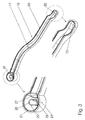
- Fig. 3 shows this fitting 15 in detail.
- the half pipe 17 first runs in a straight curve and ends in a lowered offset 22, which fits onto the step 9 with the outwardly leading first hole 10 of the plastic shell 1.
- the mouth part 16 at the other end of the half tube 17 is formed here as a liquid trap. All around the entire fitting runs continuously (also on the offset 22) a welding flange 20 with a root 21 (see below).
- the designed as a liquid trap mouthpiece 16 is a cylinder surface 24 in plan and has in the middle of an open inside the container hole 25. This is surrounded at one part of its circumference of a to the plane of the welding flange 20 and the cylinder jacket 24 reaching baffle 26 , At the transition from the cylinder jacket 24 to the half pipe 17 is still an equally high baffle 27.
- baffle 27 At the transition from the cylinder jacket 24 to the half pipe 17 is still an equally high baffle 27.
- Fig. 4 shows a half tube 37, here with a semicircular cross section.
- the transition from this to its welding flange 20 with the root 21 is here formed as a longitudinally directed bellows 38,39.
- the wall parts of the half tube 37 are zigzag in cross section. This allows the flexible welding flange to better adjust unevenness or tolerances.
- Fig. 5 shows a half tube 47 which is stiffened by a transverse rib 48 in the transverse direction.
- the rib 48 may be curved inwardly (as shown) or outwardly. If several such ribs follow each other, the half tube is flexible in the longitudinal direction and slightly variable in length.
- the mouth part 49 here has a cylindrical plug-in flange 50 with at least two notches 52 distributed over the circumference. In these, a valve indicated only by dashed lines can be inserted and clipped with the notches 52.
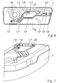
- the molding 115 is here in one piece with a series of channels, but still only an open planar part.
- One of the channels is expanded to a bubbling tank 116 having a space 117.
- the space 117 has a guide wall 119 and communicates via an opening 118 with the interior of the fuel tank in connection.
- the space 117 of the Ausperl matterers 116 is further connected via a first connecting channel 120 and a second connecting channel 121 with mouth parts 122 and 123 in connection.
- These can be considered liquid traps as in Fig. 3 or as a plug-in flange for a valve (as in Fig. 5 ) be formed.
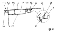
- the connecting channels 121, 122 have a relatively small cross-section, but nevertheless follow their course on both sides of their welding flanges. Where they are guided along the Ausperl matterer 116, they are united with him (see Fig. 8 ).
- a vent channel 127 of larger cross-section leads to an end portion 109, which is also connected tightly to the plastic shell 1 and surrounds the hole 10 leading to the outside. Also, this vent channel 127 with its loop 127 'has a closely following its contour welding flange. Where he is led along the bubbling tank 116, he is united with him (see Fig. 8 ).
- Fig. 8 It will be appreciated that the fitting 115 integrally forms the bubbler 116, the connection channels 120, 121 and the vent passage 127.
- the sharp edge 23 forming a root 21 of the surrounding all around the fitting welding flange 20 has penetrated into the plastic shell.
- the guide wall 119 and other intermediate walls can be connected to the plastic shell 1.
- the molding is either injected in a simple coreless form or pressed from a flat plastic plate.
- the fuel tank is either blown or its parts, here the two plastic shells are pressed or sprayed in the usual way.
- he or the respective plastic shell is brought to a temperature in which the plastic is soft and by pressing the fitting with him welded.
- the cold molded piece is pressed into the plastic shell still in the mold. Thanks to the tapered root 21 of the welding flange 20 requires not only a low insertion force.
- the region of the root near the cutting edge 23 is so thin that it melts immediately after penetration into the plastic shell 1 and with the latter enters into a particularly strong and tight connection.
- the thicker regions of the wedge-shaped cross-section of the root 21 and the welding flange 20 with the plastic shell 1. If in one of the mouth parts a valve is to be used, then it can happen soon afterwards or even before. If it is a multi-part fuel tank, finally, the two plastic shells 1.2 are joined together along their welding flange 5.
Landscapes
- Engineering & Computer Science (AREA)
- Mechanical Engineering (AREA)
- Life Sciences & Earth Sciences (AREA)
- Sustainable Development (AREA)
- Sustainable Energy (AREA)
- Chemical & Material Sciences (AREA)
- Combustion & Propulsion (AREA)
- Transportation (AREA)
- Manufacturing & Machinery (AREA)
- Cooling, Air Intake And Gas Exhaust, And Fuel Tank Arrangements In Propulsion Units (AREA)
- Details Of Rigid Or Semi-Rigid Containers (AREA)
Description
- Die Erfindung betrifft einen Kraftstoffbehälter für Kraftfahrzeuge aus Kunststoff, in dessen Innerem sich Einbauten befinden. Seine Wandung kann aus einem einzigen blasgeformtem Teil mit einer ausreichend großen Öffnung oder aus zwei gepressten oder tiefgezogenen und dann miteinander verbundenen Kunststoffschalen bestehen. Bei den genannten Verformungsverfahren wird eine Form verwendet und der Kunststoff in warmem Zustand verformt. Die Wandungen können zur Minimierung der Permeation von Kraftstoffdämpfen auch mehrschichtig sein. Die Einbauten können von verschiedener Art sein, in der Regel sind es Teile eines Entlüftungssystems, nämlich Ventile, Abscheider, Ausperlbehälter und/oder Schwimmerkammern und diese verbindende Rohre oder Schläuche.
- Bei den üblichen Kraftstoffbehältern aus Kunststoff sind die Teile des Entlüftungssystems einzeln innen an der oberen Schale entweder angeschweißt (siehe zum Beispiel die
EP 1 310 715A1 ) oder an in Durchbrechungen der Schale befestigten Schweißkronen angebracht (siehe zum Beispiel dieEP 1 084 889 A1 ), jedenfalls aber sind die einzelnen Teile durch Rohre miteinander beziehungsweise mit der Atmosphäre verbunden. Die Teile oder Schweißkronen sind durchwegs kleinflächig. - Bei der Fertigung ist die Anbringung und Verbindung der einzelnen Teile des Entlüftungssystems und deren Verbindungsrohre an der Innenseite der Kunststoffschale arbeitsaufwändig und daher kostspielig. Besonders, wenn der Kraftstoffbehälter zur besseren Raumausnutzung in einem Personenkraftwagen zerklüftet ist und die Wandungen beziehungsweise Kunststoffteile der Wandung eine tiefe Raumform haben. Die Rohre oder Schläuche hängen dann frei im Inneren des Kraftstoffbehälters und können schwingen, was sie störungsanfällig macht und Klappergeräusche erzeugen kann. Sie an der Wandung zu befestigen, erhöht den Arbeitsaufwand weiter. Schließlich sind der Querschnitt der Rohre oder Schläuche und ihr Krümmungsradius begrenzt. Ersteres beeinträchtigt die Funktion, zweiteres engt die Gestaltungsfreiheit ein.
- Aus der
DE 10 2006 059 799 A1 ist ein gattungsbildender Kraftstoffbehälter aus Kunststoff bekannt, an dessen Boden ein Schwallbehälter und an dessen Plafond Profilabschnitte in der Weise befestigt sind, dass sie Flansche mit Schweißfortsätzen haben, die in die Innenwand des warm in der Form liegenden Tankteiles eingedrückt und so stoffschlüssig mit ihr verbunden sind. Schwallbehälter und Profilabschnitte stehen miteinander in keinem Zusammenhang. Es besteht keine Verbindung mit irgendwelchen Funktionsteilen. - Es ist somit die der Erfindung zugrunde liegende Aufgabe, die Einbauten eines aus Kunststoff bestehenden Kraftstoffbehälters so auszubilden, dass mit minimalem Arbeits- Werkzeug- und Logistikaufwand das Auslangen gefunden wird und dass sie bei hoher Raumökonomie und Gestaltungsfreiheit auch funktionell verbessert sind. Die Einbauten sollen auch für Kraftstoffbehälter komplizierter Form (insbesondere mit tief profilierter oberer Wandung) geeignet sein und sollen nicht klappern.
- Erfindungsgemäß wird das mit den kennzeichnenden Merkmalen des ersten Anspruches erreicht. Dadurch dass sämtliche Einbauten zu einem Formstück zusammengefasst sind, ist eine einfache und schnelle Montage durch stoffschlüssige Verbindung mit der Wandung gegeben.
- Das Formstück ist ein flächiges Bauteil mit einer offenen Raumform, es kann somit in einer einfachen Form gespritzt oder aus einem ebenen Lappen gepresst sein. Es bildet gemeinsam mit der Wandung des Kraftstoffbehälters mindestens einen Kanal. Der entsprechende Teil des Formstückes ist gewissermaßen ein "Halbrohr". Der so gebildete Kanal ersetzt das bisher übliche Rohr. Dadurch, dass der Kanal einerseits von dem Formstück und andererseits von der Wandung gebildet ist, hat er einen geschlossenen Querschnitt, ohne dass es schwingende oder klappernde Verbindungsrohre gibt. Dadurch auch kann der Querschnitt des Kanals frei gewählt werden, was eine bessere Raumökonomie und trotzdem größere Strömungsquerschnitte erlaubt. Außerdem kann der Kanal mit sehr engem Radius gekrümmt verlaufen (was ein Rohr oder einen Schlauch abknicken würde) und selbst wieder mit Einbauten und wenn nötig örtlichen Verstärkungen versehen sein.
- Für den Toleranzausgleich und die Eignung für den Einbau in eine kompliziert geformte Kunststoffschale ist wesentlich, dass der Schweißflansch des Formstücks nicht nur der Raumform der Wandung des Kraftstoffbehälters, sondern auch der Kontur des Kanals folgt. Dadurch ist das Formstück kein großflächiges und wegen seiner Raumform steifes Bauteil. Der einen Kanal bildende Teil des Formstückes ist kaum breiter als der Kanal selbst. Er ist dadurch biegsam genug, geringfügige Maßabweichungen auszugleichen. Das Formstück ist rundum mit der Wandung des Kraftstoffbehälters verschweißt, die Schweißnaht bildet eine im Wesentlichen geschlossene Kurve.
- Zur Verbindung mit dem Inneren des Kraftstoffbehälters hat das Formstück mindestens einen zum Inneren des Kraftstoffbehälters hin offenen mit ihm einstückigen Mundteil. Dieser kann der jeweiligen Funktion beziehungsweise dem einzubauenden Bauteil entsprechend gestaltet sein.
- Über die angeführten Vorteile hinaus ist dank der Erfindung auch der Aufwand für Qualitätsprüfung und wegen der Einteiligkeit auch der für Logistik und Lagerhaltung geringer.
- Insgesamt wird mit dem so gestalteten Formstück große konstruktive Freiheit gewonnen. So kann das Formstück ohne höheren Herstellungsaufwand mehrere Kanäle bilden und der eine oder andere Kanal sogar zu einem Raum erweitert sein, der einen Behälter bildet (Anspruch 2). Diese Kanäle oder auch der Behälter können mit ihm einstückige Einbauten enthalten, etwa Verstärkungen, Diaphragmen oder Schikanen, die gegebenenfalls auch mit der Wandung des Kraftstoffbehälters verbunden sind (Anspruch 3).
- Ein zu einem Behälter erweiterter Kanal kann ohne Verbindung ins Innere des Kraftstoffbehälters sozusagen als Behälter im Behälter ausgebildet sein und mit außerhalb des Kraftstoffbehälters angeordneten Bauteilen in Verbindung stehen. Dasselbe gilt auch für nicht erweitere Kanäle. Zur Verbindung nach außen können in der Wandung des Kraftstoffbehälters an den jeweiligen Stellen Löcher ausgeschnitten sein. Das Formstück übergreift die zumindest eine Öffnung in der Wandung, die die Verbindung zur Atmosphäre oder zu einem externen Bauteil (zum Beispiel einem Aktivkohlefilter) herstellt. (Anspruch 4).
- In Weiterbildung der Erfindung ist der Mundteil ein für die Aufnahme beispielsweise eines Ventils ausgebildeter Flansch (Anspruch 5), vorzugsweise mit Rasten oder elastischen Teilen zum Einklipsen des Ventils (Anspruch 6). Herkömmliche Ventile oder Einbauteile können aber auch auf herkömmliche Weise mit dem Formstück verschweißt sein. Weiters kann der oder ein weiterer Mundteil an einem Ende eines Kanals als Tropfenabscheider ausgebildet sein (Anspruch 7). Ein solcher besteht in einer besonders einfachen und wirksamen Ausführungsform darin, dass der Mundteil des Formstücks ein kleines Loch hat, an das nach innen eine zylindrische Leitwand anschließt und auf die eine Prallwand folgt (Anspruch 8). So kann die abgeschiedene Flüssigkeit gleich durch das Loch in den Kraftstoffbehälter zurück fließen.
- Um eine dichte und haltbare Schweißverbindung zu erhalten, hat der Schweißflansch des Formstücks mindestens eine im Querschnitt keilförmige Wurzel, die im Wesentlichen normal in die Kunststoffschale eindringt (Anspruch 9). Die auf eine spitze Kante zulaufende Wurzel dringt leicht in die warme Kunststoffschale ein, sie nimmt besonders schnell deren Temperatur an und verbindet sich so fest mit ihr. Deshalb braucht das Formstück zum Einbau nicht erwärmt zu werden, was den Einbau vereinfacht.
- Unter Ausnutzung der großen Gestaltungsfreiheit kann ein einen Kanal bildender Teil des Formstückes quer zu seiner Längsrichtung mindestens eine Verstärkungsrippe aufweisen (Anspruch 10), oder gleich mehrere, gleich dem Balg einer Ziehharmonika. Ersteres zur Verstärkung in Querrichtung bei Erhaltung der Biegsamkeit in Längsrichtung; zweiteres zur Erhöhung der Biegsamkeit in Längsrichtung zum Toleranzausgleich.
-
- Fig. 1:
- Ansicht der oberen Schale eines erfindungsgemäßen Kraftstoffbehälters von unten,
- Fig. 2:
- Axonometrische Ansicht derselben, etwas vergrößert,
- Fig. 3:
- Ansicht des Formstückes der
Fig. 2 mit Details, vor der Montage, - Fig. 4:
- Detail einer Variante,
- Fig. 5:
- Detail einer weiteren Variante,
- Fig. 6:
- Ansicht einer weitergebildeten Ausführungsform eines erfindungsgemäßen Kraftstoffbehälters von unten,
- Fig. 7:
- Schnitt nach VII-VII zu
Fig. 6 , - Fig. 8:
- Detail VIII in
Fig. 7 . - In den
Fig. 1 und 2 ist bei einem aus zwei Teilen zusammengesetzten Kraftstoffbehälter die erste - obere - Kunststoffschale summarisch mit 1 bezeichnet, die zweite - untere - Kunststoffschale 2 ist inFig.7 strichliniert angedeutet. Die obere Wandung, hier die erste Kunststoffschale 1, besteht aus einem großflächigen Plafond 3, der uneben sein kann, aus rundum einer Seitenwand 4 und aus einem von der Seitenwand 4 nach außen gebördelten Verschweißflansch 5. Die Kunststoffschale 1 hat zur Versteifung längliche Verstärkungssicken 6,7 und rechteckige Verstärkungsdellen 8. An einer Stelle bildet sie eine Stufe 9 mit einem ersten Loch 10, durch das eine Verbindung ins Freie oder zu einem anderen Bauteil, etwa einem Aktivkohlefilter besteht. Dieses Loch 10 wird gegebenenfalls erst nach Anbringung der Einbauten ausgeschnitten. Ein zweites größeres Loch 11 ist für den Einbau einer Pumpeinheit oder dergleichen (nicht dargestellt) gedacht, könnte bei einem einteilig blasgeformten Kraftstoffbehälter auch für das Einbringen weiterer Einbauten, benutzt werden. - Die weiteren Einbauten, insbesondere die für die Entlüftung, sind zu einem erfindungsgemäßen Formstück 15 zusammengefasst. In
Fig. 1 ist es in seiner einfachsten Form abgebildet, in der es nur aus einem "Halbrohr" 17 und einem Mundteil 16 besteht. Der vom Formstück 15 zusammen mit der Wandung des Kraftstoffbehälters, der ersten Kunststoffschale 1, gebildete Kanal hat hier einen geschlossenen rechteckigen Querschnitt. -
Fig. 3 zeigt dieses Formstück 15 im Detail. Das Halbrohr 17 verlauft zuerst eben in einer Kurve und endet in einem abgesenkten Versatz 22, der auf die Stufe 9 mit dem nach außen führenden ersten Loch 10 der Kunststoffschale 1 passt. Der Mundteil 16 am anderen Ende des Halbrohres 17 ist hier als Flüssigkeitsfalle ausgebildet. Rundum das gesamte Formstück lauft ununterbrochen (auch über den Versatz 22) ein Schweißflansch 20 mit einer Wurzel 21 (dazu siehe weiter unten). - Der als Flüssigkeitsfalle ausgebildete Mundteil 16 ist im Grundriss ein Zylindermantel 24 und hat in der Mitte ein ins Innere des Behälters hin offenes Loch 25. Dieses ist an einem Teil seines Umfanges von einer bis zur Ebene des Schweißflansches 20 und zum Zylindermantel 24 reichenden Leitwand 26 umgeben. Am Übergang vom Zylindermantel 24 zum Halbrohr 17 ist noch eine ebenso hohe Prallwand 27. Durch das Loch 25 eintretende mit Tröpfchen beladene Dämpfe werden zwischen dem Zylindermantel 24 und der Leitwand 26 in einer Kreisbahn geführt und prallen dann an die Prallwand 27. Durch die Fliehkraft und die Prallwand werden die Tröpfchen abgeschieden. Sie laufen durch das Loch 25 zurück in den Behälter.
- Die Variante der
Fig. 4 zeigt ein Halbrohr 37, hier mit halbkreisförmigem Querschnitt. Der Übergang von diesem zu seinem Schweißflansch 20 mit der Wurzel 21 ist hier als längs gerichteter Balg 38,39 ausgebildet. Dazu sind die Wandteile des Halbrohres 37 im Querschnitt zickzackförmig. Dadurch kann sich der biegsame Schweißflansch Unebenheiten oder Toleranzen besser anpassen. - Die Variante der
Fig. 5 zeigt ein Halbrohr 47, das durch eine quer verlaufende Rippe 48 in Querrichtung versteift ist. Die Rippe 48 kann nach innen (wie abgebildet) oder nach außen gewölbt sein. Wenn mehrere solcher Rippen aufeinander folgen, ist das Halbrohr in Längsrichtung biegeweich und geringfügig längenveränderlich. Der Mundteil 49 hat hier einen zylindrischen Steckflansch 50 mit über den Umfang verteilt mindestens zwei Rasten 52. In diesen kann ein nur strichliniert angedeutetes Ventil eingesetzt und mit den Rasten 52 verklipst sein. - In den
Fig. 6, 7 und8 ist ein Ausführungsbeispiel mit einer komplizierten Entlüftungsvorrichtung zu sehen, bei dem die Vorteile der Erfindung besonders wirksam sind. Das Formstück 115 ist hier mit einer Reihe von Kanälen einstückig, aber trotzdem nur ein offener flächiger Teil. Einer der Kanäle ist zu einem Ausperlbehälter 116 mit einem Raum 117 erweitert. Der Raum 117 hat eine Leitwand 119 und steht über eine Öffnung 118 mit dem Inneren des Kraftstoffbehälters in Verbindung. Der Raum 117 des Ausperlbehälters 116 steht weiters über einen ersten Verbindungskanal 120 und einen zweiten Verbindungskanal 121 mit Mundteilen 122 beziehungsweise 123 in Verbindung. Diese können als Flüssigkeitsfalle wie inFig. 3 oder als Steckflansch für ein Ventil (wie inFig. 5 ) ausgebildet sein. Sie sind an voneinander entfernten Regionen des Kraftstoffbehälters angeordnet, um die Entlüftung lageunabhängig zu machen. Die Verbindungskanäle 121,122 haben einen relativ kleinen Querschnitt, aber trotzdem ihrem Verlauf folgend beiderseits ihre Schweißflansche. Wo sie an dem Ausperlbehälter 116 entlang geführt sind, sind sie mit ihm vereint (sieheFig. 8 ). - Von dem Ausperlbehälter 116 führt ein Entlüftungskanal 127 größeren Querschnittes zu einem Endteil 109, der auch dicht mit der Kunststoffschale 1 verbunden ist und das nach außen führende Loch 10 umgibt. Auch dieser Entlüftungskanal 127 mit seiner Schlinge 127' hat einen seiner Kontur eng folgenden Schweißflansch. Wo er an dem Ausperlbehälter 116 entlang geführt sind, ist er mit ihm vereint (siehe
Fig. 8 ). - In
Fig. 8 wird deutlich, dass das Formstück 115 einstückig den Ausperlbehälter 116, die Verbindungskanäle 120, 121 und den Entlüftungskanal 127 bildet. Im eingekreisten Detail ist zu sehen, wie die eine scharfe Schneide 23 bildende Wurzel 21 des rundum das ganze Formstück umgebenden Schweißflansches 20 in die Kunststoffschale eingedrungen ist. In derselben Weise kann auch die Leitwand 119 und weitere Zwischenwände mit der Kunststoffschale 1 verbunden sein. - Bei der Herstellung eines erfindungsgemäßen Kraftstoffbehälters wird das Formstück entweder in einer einfachen kernlosen Form gespritzt oder aus einer ebenen Kunststoffplatte gepresst. Der Kraftstoffbehälter wird entweder geblasen oder seine Teile, hier die beiden Kunststoffschalen werden in der üblichen Weise gepresst oder gespritzt. Dazu wird er oder die jeweilige Kunststoffschale auf eine Temperatur gebracht, in der der Kunststoff weich und durch Anpressen des Formstückes mit ihm verschweißbar ist. Sobald die Form zur Herstellung der Kunststoffschale geöffnet und die Schale noch heiß ist, beziehungsweise sobald der Blasvorgang beendet ist, wird das kalte Formstück in die noch in der Form befindliche Kunststoffschale eingedrückt. Dank der sich verjüngenden Wurzel 21 des Schweißflansches 20 erfordert das nicht nur eine geringe Einpresskraft.
- Der große Vorteil liegt darin, dass die Region der Wurzel nahe der Schneide 23 so dünn ist, dass sie sogleich nach dem Eindringen in die Kunststoffschale 1 aufschmilzt und mit letzterer eine besonders feste und dichte Verbindung eingeht. In der Folge verbinden sich auch die dickeren Regionen des keilförmigen Querschnittes der Wurzel 21 und der Schweißflansch 20 mit der Kunststoffschale 1. Sofern in einen der Mundteile ein Ventil einzusetzen ist, so kann das gleich danach oder auch vorher geschehen. Wenn es sich um einen aus mehreren Teilen bestehenden Kraftstoffbehälter handelt, werden schließlich die beiden Kunststoffschalen 1,2 entlang ihrer Verschweißflansche 5 miteinander verbunden.
Claims (10)
- Kraftstoffbehälter aus Kunststoff, in dessen Inneren sich Einbauten befinden, wobei an der Innenseite der Wandung (1) des Kraftstoffbehälters oder eines Teiles (1,2) dessen ein Formstück (15; 115) angebracht und mit der Wandung (1) stoffschlüssig verbunden ist,a) wobei das Formstück (15; 115) eine offene Raumform hat und zusammen mit der Innenseite der Wandung (1) mindestens einen Kanal (17; 116,120,121, 127) bildet, undb) wobei das Formstück (15; 115) rundum mit der Wandung (1) verschweißt ist, und ein eine im Wesentlichen geschlossene Kurve bildender Schweißflansch (20;40) der Kontur des mindestens einen Kanals (17; 116,120,121, 127) folgt,
dadurch gekennzeichnet, dassc) das Formstück (15; 115) zumindest Teil einer Entlüftungsvorrichtung ist, undd) das Formstück (15; 115) mindestens einen Kanal (17; 120,121,127) bildet, der mit einem zur Behälterinnenseite offenen Ende einen mit ihm einstückigen Mundteil (16; 49,50; 122,123) hat. - Kraftstoffbehälter nach Anspruch 1, dadurch gekennzeichnet, dass das Formstück mehrere Kanäle (120, 121, 127) bildet und ein Kanal (116) zumindest örtlich dergestalt erweitert ist, dass er mit der Wandung (1) einen Behälter (116) mit einem Innenraum (117) bildet.
- Kraftstoffbehälter nach Anspruch 1, dadurch gekennzeichnet, dass das Formstück (15; 115) Einbauten (26,27; 119) enthält, die mit ihm einstückig sind.
- Kraftstoffbehälter nach Anspruch 1, dadurch gekennzeichnet, dass das Formstück (15; 115) eine Öffnung (10) in der Wandung übergreift, die die Verbindung zur Atmosphäre oder zu einem externen Bauteil herstellt.
- Kraftstoffbehälter nach Anspruch 1, dadurch gekennzeichnet, dass der Mundteil (49) ein für die Aufnahme eines Ventils (51) oder dergleichen ausgebildeter Flansch ist.
- Kraftstoffbehälter nach Anspruch 5, dadurch gekennzeichnet, dass der Flansch (50) Rasten (52) oder elastische Teile zum Einklipsen des Ventils oder dergleichen hat.
- Kraftstoffbehälter nach Anspruch 1, dadurch gekennzeichnet, dass der Mundteil (16) an einem Ende eines Kanals (17) als Tropfenabscheider ausgebildet ist.
- Kraftstoffbehälter nach Anspruch 7, dadurch gekennzeichnet, dass der Mundteil (16) zur Bildung eines Tropfenabscheiders ein zum Inneren des Kraftstoffbehälters hin offenes Loch (25) hat, an das nach innen eine zylindrische Leitwand (26) anschließt, auf die eine Prallwand (27) folgt.
- Kraftstoffbehälter nach Anspruch 1, dadurch gekennzeichnet, dass der Schweißflansch (20;40) mindestens eine im Querschnitt keilförmige Wurzel (21) aufweist, die im Wesentlichen normal in die Kunststoffschale (1) eindringt.
- Kraftstoffbehälter nach Anspruch 1, dadurch gekennzeichnet, dass ein einen Kanal bildender Teil (47) des Formstückes (15; 115) quer zu seiner Längsrichtung mindestens eine Verstärkungsrippe (48) aufweist.
Applications Claiming Priority (2)
| Application Number | Priority Date | Filing Date | Title |
|---|---|---|---|
| DE102009005827 | 2009-01-22 | ||
| PCT/EP2010/050741 WO2010084179A2 (de) | 2009-01-22 | 2010-01-22 | Kraftstoffbehälter mit einbauten und verfahren zu dessen fertigung |
Publications (2)
| Publication Number | Publication Date |
|---|---|
| EP2379362A2 EP2379362A2 (de) | 2011-10-26 |
| EP2379362B1 true EP2379362B1 (de) | 2012-11-21 |
Family
ID=42313719
Family Applications (1)
| Application Number | Title | Priority Date | Filing Date |
|---|---|---|---|
| EP10709174A Not-in-force EP2379362B1 (de) | 2009-01-22 | 2010-01-22 | Kraftstoffbehälter mit einbauten und verfahren zu dessen fertigung |
Country Status (4)
| Country | Link |
|---|---|
| US (1) | US8556110B2 (de) |
| EP (1) | EP2379362B1 (de) |
| CN (1) | CN101823425B (de) |
| WO (1) | WO2010084179A2 (de) |
Cited By (2)
| Publication number | Priority date | Publication date | Assignee | Title |
|---|---|---|---|---|
| DE102015219980A1 (de) | 2015-10-14 | 2017-04-20 | Bayerische Motoren Werke Aktiengesellschaft | Behälter sowie Verfahren zur Herstellung eines Behälters für flüssige Betriebsmittel eines Kraftfahrzeugs |
| DE102015220740A1 (de) | 2015-10-23 | 2017-04-27 | Bayerische Motoren Werke Aktiengesellschaft | Behälter sowie Verfahren zur Herstellung eines Behälters für flüssige Betriebsmittel eines Kraftfahrzeugs |
Families Citing this family (3)
| Publication number | Priority date | Publication date | Assignee | Title |
|---|---|---|---|---|
| DE102014222286B4 (de) | 2014-10-31 | 2024-07-18 | Kautex Textron Gmbh & Co. Kg | Betriebsflüssigkeitsbehälter für ein Kfz aus thermoplastischem Kunststoff |
| FR3082150B1 (fr) * | 2018-06-11 | 2020-12-18 | Psa Automobiles Sa | Reservoir avec canalisation empechant un passage de carburant liquide vers un dispositif de stockage des vapeurs de carburant |
| CN115319412B (zh) * | 2022-08-08 | 2023-06-06 | 四川航天中天动力装备有限责任公司 | 一种变壁厚壳体加工工艺方法 |
Family Cites Families (20)
| Publication number | Priority date | Publication date | Assignee | Title |
|---|---|---|---|---|
| US2733775A (en) * | 1956-02-07 | dupure | ||
| US1352022A (en) * | 1919-09-29 | 1920-09-07 | Pajalic Antonio | Breather for gas-engines |
| US3583593A (en) * | 1969-09-23 | 1971-06-08 | Us Army | Variable level coagulant reservoir for self-sealing fuel tanks |
| DE3224338A1 (de) | 1981-09-09 | 1983-03-24 | Dr.Ing.H.C. F. Porsche Ag, 7000 Stuttgart | Vorrichtung zur entlueftung eines kraftstoffbehaelters |
| JPS6060032A (ja) | 1983-09-12 | 1985-04-06 | Honda Motor Co Ltd | 燃料タンクのベンチレ−シヨン装置 |
| US5398839A (en) * | 1992-10-06 | 1995-03-21 | Kleyn Die Engravers, Inc. | Compartmented fuel tank with fuel absorbent material |
| DE19825104A1 (de) | 1997-07-09 | 1999-01-14 | Mannesmann Vdo Ag | Kunststoffbehälter und Verfahren zu seiner Herstellung |
| DE59813228D1 (de) * | 1997-07-09 | 2005-12-29 | Siemens Ag | Kunststoffbehälter und verfahren zu seiner herstellung |
| US6338420B1 (en) * | 1999-06-08 | 2002-01-15 | Delphi Technologies, Inc. | Motor vehicle fuel tank and method |
| DE19932713C2 (de) | 1999-07-16 | 2001-09-06 | Mannesmann Vdo Ag | Kraftstoffbehälter |
| DE19943673A1 (de) | 1999-09-13 | 2001-03-29 | Kautex Textron Gmbh & Co Kg | Tankeinsatz und Verfahren zu dessen Herstellung |
| JP2004512211A (ja) * | 2000-08-11 | 2004-04-22 | ビステオン グローバル テクノロジーズ インコーポレイテッド | 内部コンポーネントを備えた炭化水素低放出燃料タンク |
| DE10054874C2 (de) * | 2000-11-06 | 2003-05-08 | Sig Kautex Gmbh & Co Kg | Kraftstoffbehälter |
| US6742536B2 (en) | 2001-11-13 | 2004-06-01 | Eaton Corporation | Attachment of fuel vapor vent valve to the inside of a fuel tank |
| US6834771B2 (en) | 2002-10-28 | 2004-12-28 | Kyosan Denki Co., Ltd. | Resin component welding structure |
| DE60205386T2 (de) | 2002-10-29 | 2006-05-24 | Kyosan Denki Co., Ltd. | Schweissstruktur für ein Kunststoffteil |
| FR2879121B1 (fr) * | 2004-12-15 | 2008-09-26 | Inergy Automotive Systems Res | Procede pour la connexion d'une piece tubulaire en matiere plastique a une goulotte d'un reservoir a carburant egalement en matiere plastique |
| FR2882962B1 (fr) * | 2005-03-11 | 2009-07-10 | Inergy Automotive Systems Res | Procede pour la fabrication d'un reservoir a carburant en matiere plastique |
| US20070017918A1 (en) * | 2005-07-20 | 2007-01-25 | Kirk J D | Fuel tank venting arrangement |
| DE102006059799A1 (de) * | 2006-12-15 | 2008-06-19 | Kautex Textron Gmbh & Co. Kg | Kraftstoffbehälter aus thermoplastischem Kunststoff mit Funktionseinbauten zur Be- und Entlüftung, zur Kraftstoffentnahme oder dergleichen |
-
2010
- 2010-01-21 CN CN201010002867.2A patent/CN101823425B/zh not_active Expired - Fee Related
- 2010-01-22 US US13/145,329 patent/US8556110B2/en not_active Expired - Fee Related
- 2010-01-22 EP EP10709174A patent/EP2379362B1/de not_active Not-in-force
- 2010-01-22 WO PCT/EP2010/050741 patent/WO2010084179A2/de not_active Ceased
Cited By (3)
| Publication number | Priority date | Publication date | Assignee | Title |
|---|---|---|---|---|
| DE102015219980A1 (de) | 2015-10-14 | 2017-04-20 | Bayerische Motoren Werke Aktiengesellschaft | Behälter sowie Verfahren zur Herstellung eines Behälters für flüssige Betriebsmittel eines Kraftfahrzeugs |
| DE102015220740A1 (de) | 2015-10-23 | 2017-04-27 | Bayerische Motoren Werke Aktiengesellschaft | Behälter sowie Verfahren zur Herstellung eines Behälters für flüssige Betriebsmittel eines Kraftfahrzeugs |
| DE102015220740B4 (de) | 2015-10-23 | 2022-05-25 | Bayerische Motoren Werke Aktiengesellschaft | Behälter sowie Verfahren zur Herstellung eines Behälters für flüssige Betriebsmittel eines Kraftfahrzeugs |
Also Published As
| Publication number | Publication date |
|---|---|
| EP2379362A2 (de) | 2011-10-26 |
| CN101823425A (zh) | 2010-09-08 |
| US20110278286A1 (en) | 2011-11-17 |
| WO2010084179A3 (de) | 2010-09-30 |
| US8556110B2 (en) | 2013-10-15 |
| CN101823425B (zh) | 2014-05-21 |
| WO2010084179A2 (de) | 2010-07-29 |
Similar Documents
| Publication | Publication Date | Title |
|---|---|---|
| EP2379361B1 (de) | Kraftstoffbehälter mit eingebautem zusatzbehälter | |
| EP1233900B1 (de) | Bauteil für ein kraftfahrzeug | |
| EP2285549B1 (de) | Verfahren zur herstellung eines kraftstoffbehälters für kfz sowie kraftstoffbehälter für kfz | |
| EP2150430B1 (de) | Kraftstoffbehälter für kraftfahrzeuge | |
| EP3529538B1 (de) | Bogenelement für ein lüftungssystem | |
| EP2230159B1 (de) | Verkleidungsteil in einem Kotflügel eines Kraftfahrzeugs mit strömungstechnischer Verbindung zu einer Scheinwerfereinheit | |
| DE10064522A1 (de) | Bauteil für ein Kraftfahrzeug | |
| EP2379362A2 (de) | Kraftstoffbehälter mit einbauten und verfahren zu dessen fertigung | |
| DE102015207835A1 (de) | Kraftstoffbehälter für ein Kraftfahrzeug | |
| DE602005002184T2 (de) | Absperrventil für den Wasserkasten eines Kraftfahrzeuges, und solch ein Wasserkasten | |
| DE69407505T2 (de) | Fülleinheit für einen Benzintank, insbesondere für ein Motorfahrzeug | |
| DE10315381B4 (de) | Wasserablauf für einen Kraftwagen | |
| DE19835704B4 (de) | Fahrzeugkarosserie | |
| EP2762696B1 (de) | Ausgleichsbehälter und hestellungsverfahren dieses ausgleichsbehälters | |
| DE102007015114A1 (de) | Verfahren zur Herstellung eines als Medienleitung nutzbaren Einbaumoduls und Einbaumodul | |
| EP1775168B1 (de) | Wasserablaufschlauch | |
| EP1927493A2 (de) | Spriegelanordnung für ein Cabriolet-Fahrzeug | |
| EP3034337B1 (de) | Luftführungssystem für ein kraftfahrzeug | |
| DE202012012136U1 (de) | Abdeckung mit Einfüllstutzen | |
| DE3203711C2 (de) | Klappenventil für Rohrleitungen, insbesondere für Heizungs- und/oder Belüftungsdüsen in Kraftfahrzeugen | |
| DE102008013954A1 (de) | Verdampferwanne, insbesondere für eine Kraftfahrzeug-Klimaanlage | |
| DE102008045595B4 (de) | Kraftfahrzeug-Luftfiltersystem und zugehöriges Montageverfahren | |
| EP1929219B1 (de) | Kältegerät mit wasserablauf | |
| WO2003035438A1 (de) | Modulare vorrichtung zur reinigung der windschutzscheibe eines kraftfahrzeuges | |
| EP2192337B1 (de) | Flexibles Befüllrohr aus Kunststoff |
Legal Events
| Date | Code | Title | Description |
|---|---|---|---|
| PUAI | Public reference made under article 153(3) epc to a published international application that has entered the european phase |
Free format text: ORIGINAL CODE: 0009012 |
|
| 17P | Request for examination filed |
Effective date: 20110714 |
|
| AK | Designated contracting states |
Kind code of ref document: A2 Designated state(s): AT BE BG CH CY CZ DE DK EE ES FI FR GB GR HR HU IE IS IT LI LT LU LV MC MK MT NL NO PL PT RO SE SI SK SM TR |
|
| DAX | Request for extension of the european patent (deleted) | ||
| GRAP | Despatch of communication of intention to grant a patent |
Free format text: ORIGINAL CODE: EPIDOSNIGR1 |
|
| GRAS | Grant fee paid |
Free format text: ORIGINAL CODE: EPIDOSNIGR3 |
|
| GRAA | (expected) grant |
Free format text: ORIGINAL CODE: 0009210 |
|
| AK | Designated contracting states |
Kind code of ref document: B1 Designated state(s): AT BE BG CH CY CZ DE DK EE ES FI FR GB GR HR HU IE IS IT LI LT LU LV MC MK MT NL NO PL PT RO SE SI SK SM TR |
|
| REG | Reference to a national code |
Ref country code: GB Ref legal event code: FG4D Free format text: NOT ENGLISH |
|
| REG | Reference to a national code |
Ref country code: CH Ref legal event code: EP |
|
| REG | Reference to a national code |
Ref country code: AT Ref legal event code: REF Ref document number: 584881 Country of ref document: AT Kind code of ref document: T Effective date: 20121215 |
|
| REG | Reference to a national code |
Ref country code: IE Ref legal event code: FG4D Free format text: LANGUAGE OF EP DOCUMENT: GERMAN |
|
| REG | Reference to a national code |
Ref country code: DE Ref legal event code: R096 Ref document number: 502010001701 Country of ref document: DE Effective date: 20130117 |
|
| REG | Reference to a national code |
Ref country code: NL Ref legal event code: VDEP Effective date: 20121121 |
|
| REG | Reference to a national code |
Ref country code: LT Ref legal event code: MG4D |
|
| PG25 | Lapsed in a contracting state [announced via postgrant information from national office to epo] |
Ref country code: SE Free format text: LAPSE BECAUSE OF FAILURE TO SUBMIT A TRANSLATION OF THE DESCRIPTION OR TO PAY THE FEE WITHIN THE PRESCRIBED TIME-LIMIT Effective date: 20121121 Ref country code: LT Free format text: LAPSE BECAUSE OF FAILURE TO SUBMIT A TRANSLATION OF THE DESCRIPTION OR TO PAY THE FEE WITHIN THE PRESCRIBED TIME-LIMIT Effective date: 20121121 Ref country code: FI Free format text: LAPSE BECAUSE OF FAILURE TO SUBMIT A TRANSLATION OF THE DESCRIPTION OR TO PAY THE FEE WITHIN THE PRESCRIBED TIME-LIMIT Effective date: 20121121 Ref country code: ES Free format text: LAPSE BECAUSE OF FAILURE TO SUBMIT A TRANSLATION OF THE DESCRIPTION OR TO PAY THE FEE WITHIN THE PRESCRIBED TIME-LIMIT Effective date: 20130304 Ref country code: NO Free format text: LAPSE BECAUSE OF FAILURE TO SUBMIT A TRANSLATION OF THE DESCRIPTION OR TO PAY THE FEE WITHIN THE PRESCRIBED TIME-LIMIT Effective date: 20130221 |
|
| PG25 | Lapsed in a contracting state [announced via postgrant information from national office to epo] |
Ref country code: PT Free format text: LAPSE BECAUSE OF FAILURE TO SUBMIT A TRANSLATION OF THE DESCRIPTION OR TO PAY THE FEE WITHIN THE PRESCRIBED TIME-LIMIT Effective date: 20130321 Ref country code: SI Free format text: LAPSE BECAUSE OF FAILURE TO SUBMIT A TRANSLATION OF THE DESCRIPTION OR TO PAY THE FEE WITHIN THE PRESCRIBED TIME-LIMIT Effective date: 20121121 Ref country code: GR Free format text: LAPSE BECAUSE OF FAILURE TO SUBMIT A TRANSLATION OF THE DESCRIPTION OR TO PAY THE FEE WITHIN THE PRESCRIBED TIME-LIMIT Effective date: 20130222 Ref country code: PL Free format text: LAPSE BECAUSE OF FAILURE TO SUBMIT A TRANSLATION OF THE DESCRIPTION OR TO PAY THE FEE WITHIN THE PRESCRIBED TIME-LIMIT Effective date: 20121121 Ref country code: LV Free format text: LAPSE BECAUSE OF FAILURE TO SUBMIT A TRANSLATION OF THE DESCRIPTION OR TO PAY THE FEE WITHIN THE PRESCRIBED TIME-LIMIT Effective date: 20121121 |
|
| BERE | Be: lapsed |
Owner name: MAGNA STEYR FUEL SYSTEMS GESMBH Effective date: 20130131 |
|
| PG25 | Lapsed in a contracting state [announced via postgrant information from national office to epo] |
Ref country code: EE Free format text: LAPSE BECAUSE OF FAILURE TO SUBMIT A TRANSLATION OF THE DESCRIPTION OR TO PAY THE FEE WITHIN THE PRESCRIBED TIME-LIMIT Effective date: 20121121 Ref country code: CZ Free format text: LAPSE BECAUSE OF FAILURE TO SUBMIT A TRANSLATION OF THE DESCRIPTION OR TO PAY THE FEE WITHIN THE PRESCRIBED TIME-LIMIT Effective date: 20121121 Ref country code: SK Free format text: LAPSE BECAUSE OF FAILURE TO SUBMIT A TRANSLATION OF THE DESCRIPTION OR TO PAY THE FEE WITHIN THE PRESCRIBED TIME-LIMIT Effective date: 20121121 Ref country code: DK Free format text: LAPSE BECAUSE OF FAILURE TO SUBMIT A TRANSLATION OF THE DESCRIPTION OR TO PAY THE FEE WITHIN THE PRESCRIBED TIME-LIMIT Effective date: 20121121 Ref country code: BG Free format text: LAPSE BECAUSE OF FAILURE TO SUBMIT A TRANSLATION OF THE DESCRIPTION OR TO PAY THE FEE WITHIN THE PRESCRIBED TIME-LIMIT Effective date: 20130221 |
|
| PG25 | Lapsed in a contracting state [announced via postgrant information from national office to epo] |
Ref country code: MC Free format text: LAPSE BECAUSE OF NON-PAYMENT OF DUE FEES Effective date: 20130131 Ref country code: RO Free format text: LAPSE BECAUSE OF FAILURE TO SUBMIT A TRANSLATION OF THE DESCRIPTION OR TO PAY THE FEE WITHIN THE PRESCRIBED TIME-LIMIT Effective date: 20121121 Ref country code: IT Free format text: LAPSE BECAUSE OF FAILURE TO SUBMIT A TRANSLATION OF THE DESCRIPTION OR TO PAY THE FEE WITHIN THE PRESCRIBED TIME-LIMIT Effective date: 20121121 Ref country code: NL Free format text: LAPSE BECAUSE OF FAILURE TO SUBMIT A TRANSLATION OF THE DESCRIPTION OR TO PAY THE FEE WITHIN THE PRESCRIBED TIME-LIMIT Effective date: 20121121 |
|
| PLBE | No opposition filed within time limit |
Free format text: ORIGINAL CODE: 0009261 |
|
| STAA | Information on the status of an ep patent application or granted ep patent |
Free format text: STATUS: NO OPPOSITION FILED WITHIN TIME LIMIT |
|
| REG | Reference to a national code |
Ref country code: IE Ref legal event code: MM4A |
|
| 26N | No opposition filed |
Effective date: 20130822 |
|
| PG25 | Lapsed in a contracting state [announced via postgrant information from national office to epo] |
Ref country code: BE Free format text: LAPSE BECAUSE OF NON-PAYMENT OF DUE FEES Effective date: 20130131 |
|
| PG25 | Lapsed in a contracting state [announced via postgrant information from national office to epo] |
Ref country code: HR Free format text: LAPSE BECAUSE OF FAILURE TO SUBMIT A TRANSLATION OF THE DESCRIPTION OR TO PAY THE FEE WITHIN THE PRESCRIBED TIME-LIMIT Effective date: 20121121 |
|
| REG | Reference to a national code |
Ref country code: DE Ref legal event code: R097 Ref document number: 502010001701 Country of ref document: DE Effective date: 20130822 |
|
| PG25 | Lapsed in a contracting state [announced via postgrant information from national office to epo] |
Ref country code: IE Free format text: LAPSE BECAUSE OF NON-PAYMENT OF DUE FEES Effective date: 20130122 |
|
| PG25 | Lapsed in a contracting state [announced via postgrant information from national office to epo] |
Ref country code: MT Free format text: LAPSE BECAUSE OF FAILURE TO SUBMIT A TRANSLATION OF THE DESCRIPTION OR TO PAY THE FEE WITHIN THE PRESCRIBED TIME-LIMIT Effective date: 20121121 |
|
| REG | Reference to a national code |
Ref country code: CH Ref legal event code: PL |
|
| PG25 | Lapsed in a contracting state [announced via postgrant information from national office to epo] |
Ref country code: CH Free format text: LAPSE BECAUSE OF NON-PAYMENT OF DUE FEES Effective date: 20140131 Ref country code: LI Free format text: LAPSE BECAUSE OF NON-PAYMENT OF DUE FEES Effective date: 20140131 |
|
| PG25 | Lapsed in a contracting state [announced via postgrant information from national office to epo] |
Ref country code: SM Free format text: LAPSE BECAUSE OF FAILURE TO SUBMIT A TRANSLATION OF THE DESCRIPTION OR TO PAY THE FEE WITHIN THE PRESCRIBED TIME-LIMIT Effective date: 20121121 |
|
| PG25 | Lapsed in a contracting state [announced via postgrant information from national office to epo] |
Ref country code: TR Free format text: LAPSE BECAUSE OF FAILURE TO SUBMIT A TRANSLATION OF THE DESCRIPTION OR TO PAY THE FEE WITHIN THE PRESCRIBED TIME-LIMIT Effective date: 20121121 Ref country code: CY Free format text: LAPSE BECAUSE OF FAILURE TO SUBMIT A TRANSLATION OF THE DESCRIPTION OR TO PAY THE FEE WITHIN THE PRESCRIBED TIME-LIMIT Effective date: 20121121 |
|
| REG | Reference to a national code |
Ref country code: DE Ref legal event code: R082 Ref document number: 502010001701 Country of ref document: DE Representative=s name: RAUSCH, GABRIELE, DIPL.-PHYS. DR.RER.NAT., DE |
|
| PG25 | Lapsed in a contracting state [announced via postgrant information from national office to epo] |
Ref country code: MK Free format text: LAPSE BECAUSE OF FAILURE TO SUBMIT A TRANSLATION OF THE DESCRIPTION OR TO PAY THE FEE WITHIN THE PRESCRIBED TIME-LIMIT Effective date: 20121121 Ref country code: HU Free format text: LAPSE BECAUSE OF FAILURE TO SUBMIT A TRANSLATION OF THE DESCRIPTION OR TO PAY THE FEE WITHIN THE PRESCRIBED TIME-LIMIT; INVALID AB INITIO Effective date: 20100122 Ref country code: LU Free format text: LAPSE BECAUSE OF NON-PAYMENT OF DUE FEES Effective date: 20130122 |
|
| REG | Reference to a national code |
Ref country code: FR Ref legal event code: PLFP Year of fee payment: 7 |
|
| REG | Reference to a national code |
Ref country code: AT Ref legal event code: MM01 Ref document number: 584881 Country of ref document: AT Kind code of ref document: T Effective date: 20150122 |
|
| PG25 | Lapsed in a contracting state [announced via postgrant information from national office to epo] |
Ref country code: AT Free format text: LAPSE BECAUSE OF NON-PAYMENT OF DUE FEES Effective date: 20150122 |
|
| PG25 | Lapsed in a contracting state [announced via postgrant information from national office to epo] |
Ref country code: IS Free format text: LAPSE BECAUSE OF FAILURE TO SUBMIT A TRANSLATION OF THE DESCRIPTION OR TO PAY THE FEE WITHIN THE PRESCRIBED TIME-LIMIT Effective date: 20121121 |
|
| REG | Reference to a national code |
Ref country code: FR Ref legal event code: PLFP Year of fee payment: 8 |
|
| REG | Reference to a national code |
Ref country code: FR Ref legal event code: PLFP Year of fee payment: 9 |
|
| REG | Reference to a national code |
Ref country code: DE Ref legal event code: R082 Ref document number: 502010001701 Country of ref document: DE Representative=s name: RAUSCH, GABRIELE, DIPL.-PHYS. DR.RER.NAT., DE Ref country code: DE Ref legal event code: R081 Ref document number: 502010001701 Country of ref document: DE Owner name: MAGNA ENERGY STORAGE SYSTEMS GESMBH, AT Free format text: FORMER OWNER: MAGNA STEYR FUEL SYSTEMS GESMBH, SINABELKIRCHEN, AT |
|
| PGFP | Annual fee paid to national office [announced via postgrant information from national office to epo] |
Ref country code: FR Payment date: 20230124 Year of fee payment: 14 |
|
| PGFP | Annual fee paid to national office [announced via postgrant information from national office to epo] |
Ref country code: GB Payment date: 20230119 Year of fee payment: 14 Ref country code: DE Payment date: 20230123 Year of fee payment: 14 |
|
| REG | Reference to a national code |
Ref country code: DE Ref legal event code: R119 Ref document number: 502010001701 Country of ref document: DE |
|
| GBPC | Gb: european patent ceased through non-payment of renewal fee |
Effective date: 20240122 |
|
| PG25 | Lapsed in a contracting state [announced via postgrant information from national office to epo] |
Ref country code: DE Free format text: LAPSE BECAUSE OF NON-PAYMENT OF DUE FEES Effective date: 20240801 |
|
| PG25 | Lapsed in a contracting state [announced via postgrant information from national office to epo] |
Ref country code: GB Free format text: LAPSE BECAUSE OF NON-PAYMENT OF DUE FEES Effective date: 20240122 |
|
| PG25 | Lapsed in a contracting state [announced via postgrant information from national office to epo] |
Ref country code: FR Free format text: LAPSE BECAUSE OF NON-PAYMENT OF DUE FEES Effective date: 20240131 |
|
| PG25 | Lapsed in a contracting state [announced via postgrant information from national office to epo] |
Ref country code: GB Free format text: LAPSE BECAUSE OF NON-PAYMENT OF DUE FEES Effective date: 20240122 Ref country code: FR Free format text: LAPSE BECAUSE OF NON-PAYMENT OF DUE FEES Effective date: 20240131 Ref country code: DE Free format text: LAPSE BECAUSE OF NON-PAYMENT OF DUE FEES Effective date: 20240801 |