EP2378129A2 - Vakuumpumpe - Google Patents
Vakuumpumpe Download PDFInfo
- Publication number
- EP2378129A2 EP2378129A2 EP11169894A EP11169894A EP2378129A2 EP 2378129 A2 EP2378129 A2 EP 2378129A2 EP 11169894 A EP11169894 A EP 11169894A EP 11169894 A EP11169894 A EP 11169894A EP 2378129 A2 EP2378129 A2 EP 2378129A2
- Authority
- EP
- European Patent Office
- Prior art keywords
- pump
- pumping
- chamber
- fluid
- inlet
- Prior art date
- Legal status (The legal status is an assumption and is not a legal conclusion. Google has not performed a legal analysis and makes no representation as to the accuracy of the status listed.)
- Granted
Links
Images


Classifications
-
- F—MECHANICAL ENGINEERING; LIGHTING; HEATING; WEAPONS; BLASTING
- F04—POSITIVE - DISPLACEMENT MACHINES FOR LIQUIDS; PUMPS FOR LIQUIDS OR ELASTIC FLUIDS
- F04D—NON-POSITIVE-DISPLACEMENT PUMPS
- F04D19/00—Axial-flow pumps
- F04D19/02—Multi-stage pumps
- F04D19/04—Multi-stage pumps specially adapted to the production of a high vacuum, e.g. molecular pumps
- F04D19/042—Turbomolecular vacuum pumps
-
- F—MECHANICAL ENGINEERING; LIGHTING; HEATING; WEAPONS; BLASTING
- F04—POSITIVE - DISPLACEMENT MACHINES FOR LIQUIDS; PUMPS FOR LIQUIDS OR ELASTIC FLUIDS
- F04D—NON-POSITIVE-DISPLACEMENT PUMPS
- F04D17/00—Radial-flow pumps, e.g. centrifugal pumps; Helico-centrifugal pumps
- F04D17/08—Centrifugal pumps
- F04D17/16—Centrifugal pumps for displacing without appreciable compression
- F04D17/168—Pumps specially adapted to produce a vacuum
-
- F—MECHANICAL ENGINEERING; LIGHTING; HEATING; WEAPONS; BLASTING
- F04—POSITIVE - DISPLACEMENT MACHINES FOR LIQUIDS; PUMPS FOR LIQUIDS OR ELASTIC FLUIDS
- F04D—NON-POSITIVE-DISPLACEMENT PUMPS
- F04D19/00—Axial-flow pumps
- F04D19/02—Multi-stage pumps
- F04D19/04—Multi-stage pumps specially adapted to the production of a high vacuum, e.g. molecular pumps
- F04D19/044—Holweck-type pumps
-
- F—MECHANICAL ENGINEERING; LIGHTING; HEATING; WEAPONS; BLASTING
- F04—POSITIVE - DISPLACEMENT MACHINES FOR LIQUIDS; PUMPS FOR LIQUIDS OR ELASTIC FLUIDS
- F04D—NON-POSITIVE-DISPLACEMENT PUMPS
- F04D19/00—Axial-flow pumps
- F04D19/02—Multi-stage pumps
- F04D19/04—Multi-stage pumps specially adapted to the production of a high vacuum, e.g. molecular pumps
- F04D19/046—Combinations of two or more different types of pumps
-
- F—MECHANICAL ENGINEERING; LIGHTING; HEATING; WEAPONS; BLASTING
- F04—POSITIVE - DISPLACEMENT MACHINES FOR LIQUIDS; PUMPS FOR LIQUIDS OR ELASTIC FLUIDS
- F04D—NON-POSITIVE-DISPLACEMENT PUMPS
- F04D23/00—Other rotary non-positive-displacement pumps
- F04D23/008—Regenerative pumps
-
- H—ELECTRICITY
- H01—ELECTRIC ELEMENTS
- H01J—ELECTRIC DISCHARGE TUBES OR DISCHARGE LAMPS
- H01J49/00—Particle spectrometers or separator tubes
- H01J49/02—Details
- H01J49/24—Vacuum systems, e.g. maintaining desired pressures
Definitions
- This invention relates to a vacuum pump and in particular a compound vacuum pump with multiple ports suitable for differential pumping of multiple chambers.
- a sample and carrier gas are introduced to a mass analyser for analysis.
- a mass analyser for analysis.
- One such example is given in Figure 1 .
- the first interface chamber is the highest-pressure chamber in the evacuated spectrometer system and may contain an orifice or capillary through which ions are drawn from the ion source into the first interface chamber 11.
- the second, optional interface chamber 12 may include ion optics for guiding ions from the first interface chamber 11 into the third interface chamber 14, and the third chamber 14 may include additional ion optics for guiding ions from the second interface chamber into the high vacuum chamber 10.
- the first interface chamber is at a pressure of around 1-10 mbar
- the second interface chamber (where used) is at a pressure of around 10 -1 -1 mbar
- the third interface chamber is at a pressure of around 10 -2 - 10- 3 mbar
- the high vacuum chamber is at a pressure of around 10 -5 -10 -6 mbar.
- the high vacuum chamber 10, second interface chamber 12 and third interface chamber 14 can be evacuated by means of a compound vacuum pump 16.
- the vacuum pump has two pumping sections in the form of two sets 18, 20 of turbo-molecular stages, and a third pumping section in the form of a Holweck drag mechanism 22; an alternative form of drag mechanism, such as a Siegbahn or Gaede mechanism, could be used instead.
- Each set 18, 20 of turbo-molecular stages comprises a number (three shown in Figure 1 , although any suitable number could be provided) of rotor 19a, 21 a and stator 19b, 21 b blade pairs of known angled construction.
- the Holweck mechanism 22 includes a number (two shown in Figure 1 although any suitable number could be provided) of rotating cylinders 23a and corresponding annular stators 23b and helical channels in a manner known per se.
- a first pump inlet 24 is connected to the high vacuum chamber 10, and fluid pumped through the inlet 24 passes through both sets 18, 20 of turbo-molecular stages in sequence and the Holweck mechanism 22 and exits the pump via outlet 30.
- a second pump inlet 26 is connected to the third interface chamber 14, and fluid pumped through the inlet 26 passes through set 20 of turbo-molecular stages and the Holweck mechanism 22 and exits the pump via outlet 30.
- the pump 16 also includes a third inlet 27 which can be selectively opened and closed and can, for example, make the use of an internal baffle to guide fluid into the pump 16 from the second, optional interface chamber 12.
- the first interface chamber 11 is connected to a backing pump 32, which also pumps fluid from the outlet 30 of the compound vacuum pump 16.
- the backing pump typically pumps a larger mass flow directly from the first chamber 11 than that from the outlet of the secondary vacuum pump 30.
- the pump 16 is able to provide the required vacuum levels in the chambers 10, 12, 14, with the backing pump 32 providing the required vacuum level in the chamber 11.
- the backing pump 32 is typically a relatively large, floor standing pump.
- the performance provided by the backing pump at the first interface chamber 11 can be significantly affected by the operational frequency.
- a direct on line backing pump running from a 50Hz electrical supply can produce a performance in the first chamber 11 as much as a 20% lower than the performance produced by the same pump operating at 60Hz.
- any change in the performance in the first chamber 11 would have a significant affect on the performance in the other chambers.
- the present invention seeks to solve these and other problems.
- the present invention provides a differentially pumped vacuum system comprising apparatus, for example, a mass spectrometer, having at least first and second chambers; and a vacuum pump for differentially pumping fluid from the chambers to generate a first pressure above 0.1mbar, preferably above 1 mbar, in the first chamber and a second pressure lower than the first pressure in the second chamber, the pump comprising at least first and second pump inlets each for receiving fluid from a respective pressure chamber and a plurality of pumping stages positioned relative to the inlets so that fluid received from the first chamber passes through fewer pumping stages than fluid from the second chamber, the inlets being attached to the apparatus such that at least 99% of the fluid mass pumped from the apparatus passes through at least one of the pumping stages of the pump.
- apparatus for example, a mass spectrometer, having at least first and second chambers
- a vacuum pump for differentially pumping fluid from the chambers to generate a first pressure above 0.1mbar, preferably above 1 mbar, in the first chamber and a second pressure
- the differentially pumped vacuum system may have additional, lower pressure chambers than those described above, which may be pumped by the same pumping arrangement or by a separate pumping arrangement. However, in either case, the fluid mass pumped through these additional lower pressure chambers is typically much less than 1% of the total system mass flow.
- Each pumping stage preferably comprises a dry pumping stage, that is, a pumping stage that requires no liquid or lubricant for its operation.
- the apparatus comprises a third chamber
- the pump comprises a third inlet for receiving fluid from the third chamber to generate a third pressure lower than the second pressure in the third chamber, the pumping stages being arranged such that fluid entering the pump from the third chamber passes through a greater number of pumping stages than fluid entering the pump from the second chamber.
- the pump comprises at least three pump inlets, an outlet from a first, relatively high, pressure chamber being connected to a first pump inlet, an outlet for a second, medium pressure chamber being connected to a second pump inlet, and an outlet for a third, relatively low pressure chamber being connected to a third pump inlet.
- the pump comprises at least three pumping sections, each comprising at least one pumping stage, for differentially pumping the first to third chambers.
- the pump preferably comprises a first pumping section, a second pumping section downstream from the first pumping section, and a third pumping section downstream from the second pumping section, the sections being positioned relative to the inlets such that fluid entering the pump from the third chamber passes through the first, second and third pumping sections, fluid entering the pump from the second chamber passes through, of said sections, only the second and third pumping sections, and fluid entering the pump from the first chamber passes through, of said sections, only at least part of the third pumping section.
- At least one of the first and second pumping sections comprises at least one turbo-molecular stage.
- Both of the first and second pumping sections may comprise at least one turbo-molecular stage.
- the stage of the first pumping section may be of a different size to the stage of the second pumping section.
- the stage of the second pumping section may be larger than the stage of the first pumping section to offer selective pumping performance.
- the third pumping section is arranged such that fluid passing therethrough from the second pump inlet follows a different path from fluid passing therethrough from the first pump inlet.
- the third pumping section may be arranged such that fluid passing therethrough from the first pump inlet follows only part of the path of the fluid passing therethrough from the second pump inlet.
- the third pumping section may be arranged such that fluid passing therethrough from the first pump inlet follows a path which is separate from the path of the fluid passing therethrough from the second pump inlet.
- the third pumping stage may comprise a plurality of channels, in which one or more of the channels communicate with the second pump inlet whilst the remaining channels communicate with the first pump inlet.
- the third pumping section preferably comprises at least one molecular drag stage.
- the third section comprises a multi-stage Holweck mechanism with a plurality of channels arranged as a plurality of helixes.
- the Holweck mechanism may be positioned relative to the first and second pump inlets such that fluid passing therethrough from the first pump inlet follows only part of the path of the fluid passing therethrough from the second pump inlet.
- the third pumping section comprises at least one Gaede pumping stage and/or at least one aerodynamic pumping stage for receiving fluid entering the pump from each of the first, second and third chambers.
- the Holweck mechanism may be positioned upstream from said at least one Gaede pumping stage and/or at least one aerodynamic pumping stage, and such that fluid entering the pump from the first pump inlet does not pass therethrough.
- the aerodynamic pumping stage may be a regenerative stage.
- Other types of aerodynamic mechanism may be side flow, side channel, and peripheral flow mechanisms.
- the pressure of the fluid exhaust from the pump outlet is equal to or greater than 10 mbar.
- the apparatus may comprise a fourth chamber located between the first and second chambers.
- the vacuum pump preferably comprises an optional fourth inlet for receiving fluid from the fourth chamber, the fourth inlet being positioned such that fluid entering the pump from the fourth chamber passes through, of said sections, only the third pumping section towards the pump outlet, and with the fluid entering the pump from the fourth chamber passes through a greater number of stages of the third pumping section than fluid entering the pump from the first chamber.
- the pump preferably comprises a drive shaft having mounted thereon at least one rotor element for each of the pumping stages.
- the rotor elements of at least two of the pumping sections may be located on, preferably integral with, a common impeller mounted on the drive shaft.
- rotor elements for the first and second pumping sections may be integral with the impeller.
- the third pumping section comprises a molecular drag stage
- an impeller for the molecular drag stage may be located on a rotor integral with the impeller.
- the rotor may comprise a disc substantially orthogonal to, preferably integral with, the impeller.
- the third pumping section comprises a regenerative pumping stage
- rotor elements for the regenerative pumping stage are preferably integral with the impeller.
- the system preferably comprises a backing pump connected to the pump outlet such that, in use, at least 99% of the fluid mass pumped from the apparatus passes through both the vacuum pump and the backing pump.
- the present invention provides a method of differentially evacuating a plurality of chambers of an apparatus, the method comprising the steps of providing a vacuum pump comprising at least first and second pump inlets each for receiving fluid from a respective chamber and a plurality of pumping stages positioned relative to the inlets so that fluid entering the pump from the first inlet passes through fewer pumping stages than fluid entering the pump from the second inlet, attaching the inlets of the pump to the chambers such that, in use, at least 99% of the fluid mass pumped from the apparatus passes through at least one of the pumping stages of the pump, and operating the pump to generate a first pressure above 0.1mbar in a first chamber and a second pressure lower than the first pressure in a second chamber.
- the present invention provides a differentially pumped vacuum system comprising a plurality of pressure chambers; and a vacuum pump attached thereto and comprising a plurality of pump inlets each for receiving fluid from a respective pressure chamber, and a plurality of pumping stages for differentially pumping the chambers; wherein a pumping stage arranged to pump fluid from the pressure chamber in which the highest pressure is to be generated comprises a Gaede pumping stage or an aerodynamic pumping stage.
- This system may be a mass spectrometer system, a coating system, or other form of system comprising a plurality of differentially pumped chambers.
- the present invention provides a method of differentially evacuating a plurality of chambers, the method comprising the steps of providing a vacuum pump comprising a plurality of pump inlets each for receiving fluid from a respective pressure chamber, and a plurality of pumping stages for differentially pumping the chambers; and attaching the pump to the chambers such that a pumping stage for pumping fluid from the pressure chamber in which the highest pressure is to be generated comprises a Gaede pumping stage or an aerodynamic pumping stage.
- the present invention provides a compound multi-port vacuum pump comprising first, second and third pumping sections, a first pump inlet through which fluid can enter the pump and pass through each of the pumping sections towards a pump outlet, a second pump inlet through which fluid can enter the pump and pass through only the second and third pumping sections towards the outlet, an optional third pump inlet through which fluid can enter the pump and pass through only the third pumping section towards the outlet, and a fourth inlet through which fluid can enter the pump and pass through only part of the third pumping section towards the outlet.
- the present invention also provides a differentially pumped vacuum system comprising a plurality of chambers and a pump as aforementioned for evacuating each of the chambers.
- the system preferably comprises a backing pump having an inlet connected to the pump outlet for receiving fluid exhaust from the pump.
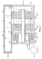
- Figure 2 illustrates a first embodiment of a compound multi port vacuum pump 100 suitable for evacuating more than 99% of the total mass flow in the differentially pumped mass spectrometer system described above with reference to Figure 1 .
- the compound multi port vacuum pump 100 comprises a multi-component body 102 within which is mounted a drive shaft 104. Rotation of the shaft is effected by a motor (not shown), for example, a brushless dc motor, positioned about the shaft 104.
- the shaft 104 is mounted on opposite bearings (not shown).
- the drive shaft 104 may be supported by a hybrid permanent magnet bearing and oil lubricated bearing system.
- the pump includes at least three pumping sections 106, 108, 112.
- the first pumping section 106 comprises a set of turbo-molecular stages.
- the set of turbo-molecular stages 106 comprises four rotor blades and three stator blades of known angled construction.
- a rotor blade is indicated at 107a and a stator blade is indicated at 107b.
- the rotor blades 107a are mounted on the drive shaft 104.
- the second pumping section 108 is similar to the first pumping section 106, and also comprises a set of turbo-molecular stages.
- the set of turbo-molecular stages 108 also comprises four rotor blades and three stator blades of known angled construction.
- a rotor blade is indicated at 109a and a stator blade is indicated at 109b.
- the rotor blades 109a are also mounted on the drive shaft 104.
- a third pumping section 112 Downstream of the first and second pumping sections is a third pumping section 112 in the form of a molecular drag mechanism, for example, a Holweck drag mechanism.
- the Holweck mechanism comprises two rotating cylinders 113a, 113b and corresponding annular stators 114a, 114b having helical channels formed therein in a manner known per se.
- the rotating cylinders 113a, 113b are preferably formed from a carbon fibre material, and are mounted on a disc 115, which is located on the drive shaft 104.
- the disc 115 is also mounted on with the drive shaft 104.
- a pump outlet 116 Downstream of the Holweck mechanism 112 is a pump outlet 116.
- a backing pump 150 backs the pump 100 via outlet 116.
- the pump 100 has three inlets 120, 122, 124; although only three inlets are used in this embodiment, the pump may have an additional, optional inlet indicated at 126, which can be selectively opened and closed and can, for example, make the use of internal baffles to guide different flow streams to particular portions of a mechanism.
- the low fluid pressure inlet 120 is located upstream of all of the pumping sections.
- the middle fluid pressure inlet 122 is located interstage the first pumping section 106 and the second pumping section 108.
- the high fluid pressure inlet 124 may be located upstream of or, as illustrated in Figure 2 , between the stages of the Holweck mechanism 112, such that all of the stages of the Holweck mechanism are in fluid communication with the other inlets 120, 122, whilst, in the arrangement illustrated in Figure 2 , only a portion (one or more) of the stages are in fluid communication with the third inlet 124.
- the optional inlet 126 is located interstage the second pumping section 108 and the Holweck mechanism 112, such that all of the stages of the Holweck mechanism 112 are in fluid communication with the optional inlet 126.
- each inlet is connected to a respective chamber of the differentially pumped mass spectrometer system.
- inlet 120 is connected to a low pressure chamber 10
- inlet 122 is connected to a middle pressure chamber 14
- inlet 124 is connected to the highest pressure chamber 11.
- the optional inlet 126 is opened and connected to this chamber 12.
- Additional lower pressure chambers may be added to the system, and may be pumped by separate means, however, the mass flow of these additional chambers is typically much less than 1 % of the total mass flow of the spectrometer system.
- Fluid passing through inlet 120 from the low pressure chamber 10 passes through the first pumping section 106, through the second pumping section 108, through all of the channels of the Holweck mechanism 112 and exits the pump 100 via pump outlet 116.
- Fluid passing through inlet 122 from the middle pressure chamber 14 enters the pump 100, passes through the second pumping section 108, through all of the channels of the Holweck mechanism 112 and exits the pump 100 via pump outlet 116.
- Fluid passing through inlet 124 from the high pressure chamber 11 enters the pump 100, passes through at least a portion of the channels of the Holweck mechanism and exits the pump via pump outlet 116. If opened, fluid passing through inlet 126 from chamber 12 enters the pump 100, passes through all of the channels of the Holweck mechanism 112 and exits the pump 100 via pump outlet 116.
- the first interface chamber 11 is at a pressure above 0.1 mbar, preferably around 1-10 mbar
- the second interface chamber 12 (where used) is at a pressure of around 10 -1 -1 mbar
- the third interface chamber 14 is at a pressure of around 10 -2 -10 -3 mbar
- the high vacuum chamber 10 is at a pressure of around 10 -5 -10 -6 mbar.
- a particular advantage of the embodiment described above is that, by enabling the high pressure chamber of the differentially pumped mass spectrometer system to be directly pumped by the same compound multi port vacuum pump 100 that pumps the second and third highest pressure chambers, rather than by the backing pump 150, the compound multi port vacuum pump is able to manage more than 99% of the total fluid mass flow of the mass spectrometer system.
- the performance of the first chamber and the rest of the internally linked spectrometer system can be increased without increasing the size of the backing pump.
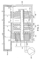
- Figure 3 provides a second embodiment of a vacuum pump 200 suitable for evacuating more than 99% of the total mass flow from a differentially pumped mass spectrometer system and is similar to the first embodiment, save that the third pumping section also includes at least one aerodynamic stage 210, in this example in the form of an aerodynamic regenerative stage, located downstream of the Holweck mechanism 212.
- the regenerative stage 210 comprises a plurality of rotors in the form of an annular array of raised rings 211 a mounted on, or integral with, the disc 215 of the Holweck mechanism 212.
- rotors 107, 109, of the turbo-molecular sections 106, 108, the rotating disc 215 of the Holweck mechanism 212 and the rotors 211 a of the regenerative stage 210 may be located on a common impeller 245, which is mounted on the drive shaft 204, with the carbon fibre rotating cylinder 213a of the Holweck mechanism 212 being mounted on the rotating disc 215 following machining of these integral rotary elements.
- rotary elements may be integral with the impeller 245, with the remaining elements being mounted on the drive shaft 204 as in the first embodiment, or located on another impeller, as required.
- the right (as shown) end of the impeller 245 may be supported by a magnetic bearing, with permanent magnets of this bearing being located on the impeller, and the left (as shown) end of the drive shaft 204 may be supported by a lubricated bearing.
- Stator 214b of the Holweck mechanism 212 can also form the stator of the regenerative stage 210, and has formed therein an annular channel 211 b within which the rotors 211 a rotate.
- the channel 211 b has a cross sectional area greater than that of the individual rotors 211 a, except for a small part of the channel known as a "stripper" which has a reduced cross section providing a close clearance for the rotors.
- fluid pumped from each of the chambers of the differentially pumped mass spectrometer system enters the annular channel 211 b via an inlet positioned adjacent one end of the stripper and the fluid is urged by means of the rotors 211 a on the rotating disc 215 along the channel 211 b until it strikes the other end of the stripper, and the fluid is then urged through the outlet 216 situated on that other end of the stripper.
- the vacuum pump 200 can generate a similar performance advantage in the chambers of the differentially pumped mass spectrometer system as the vacuum pump 100 of the first embodiment.
- this second embodiment can also offer two further distinct advantages.
- the first of these is the consistency of the system performance when backed by pumps with different levels of performance, for example a backing pump operating directly on line at 50 or 60Hz.
- the variation in system performance will be as low as 1 % if the frequency of operation of the backing pump 250 is varied between 50Hz and 60Hz, thus providing the user with a flexible pumping arrangement with stable system performance.
- the second additional advantage of the second embodiment is that by providing an additional pumping stage downstream of the Holweck section, this arrangement of the vacuum pump can enable the capacity, and thus the size, of the backing pump 250 to be significantly reduced in comparison to the first embodiment.
- the vacuum pump 200 can exhaust fluid at a pressure of above 10mbar.
- the vacuum pump 100 of the first embodiment typically exhausts fluid at a pressure of around 1-10 mbar, and so the size of the backing pump 250 can be reduced significantly in comparison to the backing pump 150 of the first embodiment. It is anticipated that this size reduction could be as much as a factor of 10 in some mass spectrometer systems without adversely affecting system performance.
- the rotors 211 a of the regenerative stage 210 are surrounded by the rotating cylinder 213a of the Holweck section 212.
- the regenerative section 210 can be conveniently included in the vacuum pump 100 of the first embodiment with little, or no, increase in the overall length of the vacuum pump.
- the whole pumping system of the second embodiment including both vacuum pump 200 and backing pump 250, could be reduced in size and possibly conveniently housed within a bench-top mounted enclosure.
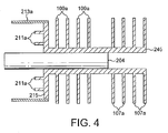
- Figure 5 provides a third embodiment of a vacuum pump 260 suitable for evacuating more than 99% of the total mass flow from a differentially pumped mass spectrometer system and is similar to the second embodiment, save that fluid passing through inlet 124 from the high pressure chamber 11 enters the pump 250, passes through the aerodynamic stage 210 without passing through the Holweck mechanism 212, and exits the pump via pump outlet 216.
- at least part of the aerodynamic pumping stage 210 may be replaced by a Gaede, or other molecular drag, mechanism 300.
- the extent to which the aerodynamic pumping stage 210 is replaced by a Gaede mechanism 300 depends on the required pumping performance of the vacuum pump 260.
- the regenerative stage 210 may be either wholly replaced or, as depicted, only partially replaced by a Gaede mechanism.
- a differentially pumped mass spectrometer system comprising a mass spectrometer having a plurality of pressure chambers; and a vacuum pump attached thereto and comprising a plurality of pump inlets each for receiving fluid from a respective pressure chamber and a plurality of pumping stages for differentially pumping fluid from the chambers; whereby, in use, at least 99% of the fluid mass pumped from the spectrometer passes through one or more of the pumping stages of the vacuum pump.
Landscapes
- Engineering & Computer Science (AREA)
- Mechanical Engineering (AREA)
- General Engineering & Computer Science (AREA)
- Chemical & Material Sciences (AREA)
- Analytical Chemistry (AREA)
- Non-Positive Displacement Air Blowers (AREA)
- Structures Of Non-Positive Displacement Pumps (AREA)
- Electrophonic Musical Instruments (AREA)
Applications Claiming Priority (4)
| Application Number | Priority Date | Filing Date | Title |
|---|---|---|---|
| GB0322888A GB0322888D0 (en) | 2003-09-30 | 2003-09-30 | Vacuum pump |
| GBGB0409139.3A GB0409139D0 (en) | 2003-09-30 | 2004-04-23 | Vacuum pump |
| PCT/GB2004/004046 WO2005040615A2 (en) | 2003-09-30 | 2004-09-23 | Vacuum pump |
| EP04768590.4A EP1668254B1 (de) | 2003-09-30 | 2004-09-23 | Vakuumpumpe |
Related Parent Applications (3)
| Application Number | Title | Priority Date | Filing Date |
|---|---|---|---|
| EP04768590.4 Division | 2004-09-23 | ||
| EP04768590.4A Division-Into EP1668254B1 (de) | 2003-09-30 | 2004-09-23 | Vakuumpumpe |
| EP04768590.4A Division EP1668254B1 (de) | 2003-09-30 | 2004-09-23 | Vakuumpumpe |
Publications (3)
| Publication Number | Publication Date |
|---|---|
| EP2378129A2 true EP2378129A2 (de) | 2011-10-19 |
| EP2378129A3 EP2378129A3 (de) | 2017-05-31 |
| EP2378129B1 EP2378129B1 (de) | 2020-02-05 |
Family
ID=34424883
Family Applications (4)
| Application Number | Title | Priority Date | Filing Date |
|---|---|---|---|
| EP04768590.4A Expired - Lifetime EP1668254B1 (de) | 2003-09-30 | 2004-09-23 | Vakuumpumpe |
| EP11169894.0A Expired - Lifetime EP2378129B1 (de) | 2003-09-30 | 2004-09-23 | Vakuumpumpe |
| EP11169892.4A Expired - Lifetime EP2375080B1 (de) | 2003-09-30 | 2004-09-23 | Vakuumpumpe |
| EP04768653.0A Expired - Lifetime EP1668255B2 (de) | 2003-09-30 | 2004-09-23 | Vakuumpumpe |
Family Applications Before (1)
| Application Number | Title | Priority Date | Filing Date |
|---|---|---|---|
| EP04768590.4A Expired - Lifetime EP1668254B1 (de) | 2003-09-30 | 2004-09-23 | Vakuumpumpe |
Family Applications After (2)
| Application Number | Title | Priority Date | Filing Date |
|---|---|---|---|
| EP11169892.4A Expired - Lifetime EP2375080B1 (de) | 2003-09-30 | 2004-09-23 | Vakuumpumpe |
| EP04768653.0A Expired - Lifetime EP1668255B2 (de) | 2003-09-30 | 2004-09-23 | Vakuumpumpe |
Country Status (8)
| Country | Link |
|---|---|
| US (4) | US7866940B2 (de) |
| EP (4) | EP1668254B1 (de) |
| JP (5) | JP5546094B2 (de) |
| CN (3) | CN102062109B (de) |
| AT (1) | ATE535715T1 (de) |
| CA (4) | CA2747137C (de) |
| GB (1) | GB0409139D0 (de) |
| WO (2) | WO2005033520A1 (de) |
Cited By (1)
| Publication number | Priority date | Publication date | Assignee | Title |
|---|---|---|---|---|
| EP3112688A1 (de) * | 2015-07-01 | 2017-01-04 | Pfeiffer Vacuum GmbH | Splitflow-vakuumpumpe sowie vakuum-system mit einer splitflow-vakuumpumpe |
Families Citing this family (39)
| Publication number | Priority date | Publication date | Assignee | Title |
|---|---|---|---|---|
| GB0322883D0 (en) * | 2003-09-30 | 2003-10-29 | Boc Group Plc | Vacuum pump |
| GB0409139D0 (en) * | 2003-09-30 | 2004-05-26 | Boc Group Plc | Vacuum pump |
| DE102006020710A1 (de) * | 2006-05-04 | 2007-11-08 | Pfeiffer Vacuum Gmbh | Vakuumpumpe mit Gehäuse |
| US20120027583A1 (en) * | 2006-05-04 | 2012-02-02 | Bernd Hofmann | Vacuum pump |
| US8288719B1 (en) * | 2006-12-29 | 2012-10-16 | Griffin Analytical Technologies, Llc | Analytical instruments, assemblies, and methods |
| DE102007010068B4 (de) * | 2007-02-28 | 2024-06-13 | Thermo Fisher Scientific (Bremen) Gmbh | Vakuumpumpe oder Vakuumapparatur mit Vakuumpumpe |
| DE102007027352A1 (de) * | 2007-06-11 | 2008-12-18 | Oerlikon Leybold Vacuum Gmbh | Massenspektrometer-Anordnung |
| GB2466156B8 (en) * | 2007-09-07 | 2015-10-14 | Ionics Mass Spectrometry Group | Multi-pressure stage mass spectrometer and methods |
| CN101398406B (zh) * | 2007-09-30 | 2012-03-07 | 孔令昌 | 便携式质谱计 |
| DE102008009715A1 (de) * | 2008-02-19 | 2009-08-20 | Oerlikon Leybold Vacuum Gmbh | Vakuumpump-System und Verwendung einer Mehrstufen-Vakuumpumpe |
| WO2009142905A1 (en) * | 2008-05-20 | 2009-11-26 | Sundew Technologies, Llc | Deposition method and apparatus |
| KR101297743B1 (ko) | 2008-10-10 | 2013-08-20 | 가부시키가이샤 아루박 | 드라이 펌프 |
| GB0901872D0 (en) * | 2009-02-06 | 2009-03-11 | Edwards Ltd | Multiple inlet vacuum pumps |
| GB2472638B (en) * | 2009-08-14 | 2014-03-19 | Edwards Ltd | Vacuum system |
| GB2474507B (en) | 2009-10-19 | 2016-01-27 | Edwards Ltd | Vacuum pump |
| DE102010019940B4 (de) * | 2010-05-08 | 2021-09-23 | Pfeiffer Vacuum Gmbh | Vakuumpumpstufe |
| DE102012003680A1 (de) | 2012-02-23 | 2013-08-29 | Pfeiffer Vacuum Gmbh | Vakuumpumpe |
| WO2014125238A1 (en) * | 2013-02-15 | 2014-08-21 | Edwards Limited | Vacuum pump |
| DE202013005458U1 (de) | 2013-06-15 | 2014-09-16 | Oerlikon Leybold Vacuum Gmbh | Vakuumpumpe |
| DE102013214662A1 (de) * | 2013-07-26 | 2015-01-29 | Pfeiffer Vacuum Gmbh | Vakuumpumpe |
| GB201314841D0 (en) | 2013-08-20 | 2013-10-02 | Thermo Fisher Scient Bremen | Multiple port vacuum pump system |
| DE102013109637A1 (de) * | 2013-09-04 | 2015-03-05 | Pfeiffer Vacuum Gmbh | Vakuumpumpe sowie Anordnung mit einer Vakuumpumpe |
| DE102014101257A1 (de) | 2014-02-03 | 2015-08-06 | Pfeiffer Vacuum Gmbh | Vakuumpumpe |
| EP3032106B1 (de) * | 2014-12-08 | 2020-02-12 | Pfeiffer Vacuum Gmbh | Vakuumpumpe |
| GB2533153B (en) * | 2014-12-12 | 2017-09-20 | Thermo Fisher Scient (Bremen) Gmbh | Vacuum system |
| DE102014226038A1 (de) * | 2014-12-16 | 2016-06-16 | Carl Zeiss Microscopy Gmbh | Druckreduzierungseinrichtung, Vorrichtung zur massenspektrometrischen Analyse eines Gases und Reinigungsverfahren |
| US9368335B1 (en) | 2015-02-02 | 2016-06-14 | Thermo Finnigan Llc | Mass spectrometer |
| JP6488898B2 (ja) | 2015-06-09 | 2019-03-27 | 株式会社島津製作所 | 真空ポンプおよび質量分析装置 |
| JP6578838B2 (ja) * | 2015-09-15 | 2019-09-25 | 株式会社島津製作所 | 真空ポンプおよび質量分析装置 |
| EP3327293B1 (de) * | 2016-11-23 | 2019-11-06 | Pfeiffer Vacuum Gmbh | Vakuumpumpe mit mehreren einlässen |
| JP7108377B2 (ja) * | 2017-02-08 | 2022-07-28 | エドワーズ株式会社 | 真空ポンプ、真空ポンプに備わる回転部、およびアンバランス修正方法 |
| GB201715151D0 (en) * | 2017-09-20 | 2017-11-01 | Edwards Ltd | A drag pump and a set of vacuum pumps including a drag pump |
| KR101838660B1 (ko) * | 2017-12-04 | 2018-03-14 | (주)대명엔지니어링 | 진공 펌프 |
| GB2569633A (en) * | 2017-12-21 | 2019-06-26 | Edwards Ltd | A vacuum pumping arrangement and method of cleaning the vacuum pumping arrangement |
| DE202018000285U1 (de) * | 2018-01-18 | 2019-04-23 | Leybold Gmbh | Vakuumpumpen-System |
| DE102018119747B3 (de) * | 2018-08-14 | 2020-02-13 | Bruker Daltonik Gmbh | Turbomolekularpumpe für massenspektrometer |
| GB2584603B (en) * | 2019-04-11 | 2021-10-13 | Edwards Ltd | Vacuum chamber module |
| EP3623634B1 (de) * | 2019-08-13 | 2022-04-06 | Pfeiffer Vacuum Gmbh | Vakuumpumpe umfassend eine holweckpumpstufe und zwei seitenkanalpumpstufen |
| US11710950B2 (en) | 2021-01-20 | 2023-07-25 | Te Connectivity Solutions Gmbh | Cutting blade and cutting depth control device |
Family Cites Families (45)
| Publication number | Priority date | Publication date | Assignee | Title |
|---|---|---|---|---|
| DE2409857B2 (de) | 1974-03-01 | 1977-03-24 | Leybold-Heraeus GmbH & Co KG, 5000Köln | Turbomolekularvakuumpumpe mit zumindest teilweise glockenfoermig ausgebildetem rotor |
| DE2442614A1 (de) * | 1974-09-04 | 1976-03-18 | Siemens Ag | Turbomolekularpumpe |
| JPS6172896A (ja) | 1984-09-17 | 1986-04-14 | Japan Atom Energy Res Inst | 高速回転ポンプ |
| JPS62279282A (ja) * | 1986-05-27 | 1987-12-04 | Mitsubishi Electric Corp | タ−ボ分子ポンプ |
| JPS6355396A (ja) * | 1986-08-21 | 1988-03-09 | Hitachi Ltd | タ−ボ真空ポンプ |
| JPS6375386A (ja) | 1986-09-18 | 1988-04-05 | Mitsubishi Heavy Ind Ltd | ハイブリツド真空ポンプ |
| US5020969A (en) † | 1988-09-28 | 1991-06-04 | Hitachi, Ltd. | Turbo vacuum pump |
| JP2585420B2 (ja) | 1989-04-04 | 1997-02-26 | 株式会社日立製作所 | ターボ真空ポンプ |
| JPH02108895A (ja) † | 1988-10-17 | 1990-04-20 | Hitachi Ltd | ターボ真空ポンプ |
| JPH02136595A (ja) | 1988-11-16 | 1990-05-25 | Anelva Corp | 真空ポンプ |
| ATE117410T1 (de) * | 1990-07-06 | 1995-02-15 | Cit Alcatel | Zweite stufe für mechanische vakuumpumpeinheit und lecküberwachungssystem zur anwendung dieser einheit. |
| DE4228313A1 (de) * | 1992-08-26 | 1994-03-03 | Leybold Ag | Gegenstrom-Lecksucher mit Hochvakuumpumpe |
| US5733104A (en) * | 1992-12-24 | 1998-03-31 | Balzers-Pfeiffer Gmbh | Vacuum pump system |
| EP0603694A1 (de) * | 1992-12-24 | 1994-06-29 | BALZERS-PFEIFFER GmbH | Vakuumpumpsystem |
| JP2656199B2 (ja) * | 1993-01-11 | 1997-09-24 | アプライド マテリアルズ インコーポレイテッド | 真空チャンバの開放方法及びpvd装置 |
| DE4314418A1 (de) | 1993-05-03 | 1994-11-10 | Leybold Ag | Reibungsvakuumpumpe mit unterschiedlich gestalteten Pumpenabschnitten |
| CN1110376A (zh) * | 1994-04-16 | 1995-10-18 | 储继国 | 拖动分子泵 |
| DE19508566A1 (de) * | 1995-03-10 | 1996-09-12 | Balzers Pfeiffer Gmbh | Molekularvakuumpumpe mit Kühlgaseinrichtung und Verfahren zu deren Betrieb |
| JP3095338B2 (ja) * | 1995-06-19 | 2000-10-03 | 富士通株式会社 | ターボ分子ポンプ |
| GB9725146D0 (en) * | 1997-11-27 | 1998-01-28 | Boc Group Plc | Improvements in vacuum pumps |
| JPH11230036A (ja) * | 1998-02-18 | 1999-08-24 | Ebara Corp | 真空排気システム |
| DE19821634A1 (de) * | 1998-05-14 | 1999-11-18 | Leybold Vakuum Gmbh | Reibungsvakuumpumpe mit Stator und Rotor |
| GB9810872D0 (en) * | 1998-05-20 | 1998-07-22 | Boc Group Plc | Improved vacuum pump |
| WO1999061799A1 (de) * | 1998-05-26 | 1999-12-02 | Leybold Vakuum Gmbh | Reibungsvakuumpumpe mit chassis, rotor und gehäuse sowie einrichtung, ausgerüstet mit einer reibungsvakuumpumpe dieser art |
| US6193461B1 (en) * | 1999-02-02 | 2001-02-27 | Varian Inc. | Dual inlet vacuum pumps |
| DE19915307A1 (de) * | 1999-04-03 | 2000-10-05 | Leybold Vakuum Gmbh | Reibungsvakuumpumpe mit aus Welle und Rotor bestehender Rotoreinheit |
| DE19930952A1 (de) * | 1999-07-05 | 2001-01-11 | Pfeiffer Vacuum Gmbh | Vakuumpumpe |
| GB9927493D0 (en) * | 1999-11-19 | 2000-01-19 | Boc Group Plc | Improved vacuum pumps |
| DE10022062A1 (de) * | 2000-05-06 | 2001-11-08 | Leybold Vakuum Gmbh | Maschine, vorzugsweise Vakuumpumpe, mit Magnetlagern |
| JP2001323892A (ja) * | 2000-05-16 | 2001-11-22 | Shimadzu Corp | ターボ型真空機器 |
| DE10032607B4 (de) * | 2000-07-07 | 2004-08-12 | Leo Elektronenmikroskopie Gmbh | Teilchenstrahlgerät mit einer im Ultrahochvakuum zu betreibenden Teilchenquelle und kaskadenförmige Pumpanordnung für ein solches Teilchenstrahlgerät |
| US6793466B2 (en) * | 2000-10-03 | 2004-09-21 | Ebara Corporation | Vacuum pump |
| JP2002138987A (ja) * | 2000-10-31 | 2002-05-17 | Seiko Instruments Inc | 真空ポンプ |
| DE10055057A1 (de) * | 2000-11-07 | 2002-05-08 | Pfeiffer Vacuum Gmbh | Leckdetektorpumpe |
| JP2002285987A (ja) | 2001-03-28 | 2002-10-03 | Chiba Seimitsu:Kk | 小型真空ポンプ |
| CN1399076A (zh) * | 2001-07-27 | 2003-02-26 | 大晃机械工业株式会社 | 真空泵 |
| GB0124731D0 (en) * | 2001-10-15 | 2001-12-05 | Boc Group Plc | Vacuum pumps |
| JP3961273B2 (ja) * | 2001-12-04 | 2007-08-22 | Bocエドワーズ株式会社 | 真空ポンプ |
| GB0229355D0 (en) * | 2002-12-17 | 2003-01-22 | Boc Group Plc | Vacuum pumping arrangement |
| GB0229352D0 (en) * | 2002-12-17 | 2003-01-22 | Boc Group Plc | Vacuum pumping arrangement and method of operating same |
| GB0229353D0 (en) * | 2002-12-17 | 2003-01-22 | Boc Group Plc | Vacuum pumping system and method of operating a vacuum pumping arrangement |
| GB0229356D0 (en) * | 2002-12-17 | 2003-01-22 | Boc Group Plc | Vacuum pumping arrangement |
| ITTO20030421A1 (it) * | 2003-06-05 | 2004-12-06 | Varian Spa | Pompa da vuoto compatta |
| GB0409139D0 (en) | 2003-09-30 | 2004-05-26 | Boc Group Plc | Vacuum pump |
| GB0411426D0 (en) * | 2004-05-21 | 2004-06-23 | Boc Group Plc | Pumping arrangement |
-
2004
- 2004-04-23 GB GBGB0409139.3A patent/GB0409139D0/en not_active Ceased
- 2004-09-23 CN CN2011100487470A patent/CN102062109B/zh not_active Expired - Lifetime
- 2004-09-23 US US10/574,027 patent/US7866940B2/en active Active
- 2004-09-23 WO PCT/GB2004/004110 patent/WO2005033520A1/en not_active Ceased
- 2004-09-23 CA CA2747137A patent/CA2747137C/en not_active Expired - Fee Related
- 2004-09-23 AT AT04768653T patent/ATE535715T1/de active
- 2004-09-23 JP JP2006530555A patent/JP5546094B2/ja not_active Expired - Fee Related
- 2004-09-23 CA CA2563306A patent/CA2563306C/en not_active Expired - Fee Related
- 2004-09-23 CN CN2004800284031A patent/CN1860301B/zh not_active Expired - Lifetime
- 2004-09-23 EP EP04768590.4A patent/EP1668254B1/de not_active Expired - Lifetime
- 2004-09-23 CA CA2747136A patent/CA2747136C/en not_active Expired - Fee Related
- 2004-09-23 WO PCT/GB2004/004046 patent/WO2005040615A2/en not_active Ceased
- 2004-09-23 JP JP2006530557A patent/JP4843493B2/ja not_active Expired - Fee Related
- 2004-09-23 CN CN2004800268965A patent/CN101124409B/zh not_active Expired - Lifetime
- 2004-09-23 EP EP11169894.0A patent/EP2378129B1/de not_active Expired - Lifetime
- 2004-09-23 US US10/572,894 patent/US8851865B2/en active Active
- 2004-09-23 CA CA2563234A patent/CA2563234C/en not_active Expired - Fee Related
- 2004-09-23 EP EP11169892.4A patent/EP2375080B1/de not_active Expired - Lifetime
- 2004-09-23 EP EP04768653.0A patent/EP1668255B2/de not_active Expired - Lifetime
-
2010
- 2010-12-13 US US12/966,566 patent/US8672607B2/en active Active
-
2011
- 2011-04-13 JP JP2011089466A patent/JP5637919B2/ja not_active Expired - Fee Related
-
2013
- 2013-10-10 JP JP2013213092A patent/JP2014001743A/ja active Pending
- 2013-10-10 JP JP2013213093A patent/JP5809218B2/ja not_active Expired - Fee Related
-
2014
- 2014-08-28 US US14/471,698 patent/US9249805B2/en not_active Expired - Fee Related
Non-Patent Citations (1)
| Title |
|---|
| None |
Cited By (1)
| Publication number | Priority date | Publication date | Assignee | Title |
|---|---|---|---|---|
| EP3112688A1 (de) * | 2015-07-01 | 2017-01-04 | Pfeiffer Vacuum GmbH | Splitflow-vakuumpumpe sowie vakuum-system mit einer splitflow-vakuumpumpe |
Also Published As
Similar Documents
| Publication | Publication Date | Title |
|---|---|---|
| EP1668254B1 (de) | Vakuumpumpe | |
| JP5378432B2 (ja) | ポンピング装置 | |
| EP1668257B1 (de) | Vakuumpumpe | |
| EP1807627B1 (de) | Pumpanordnung |
Legal Events
| Date | Code | Title | Description |
|---|---|---|---|
| AC | Divisional application: reference to earlier application |
Ref document number: 1668254 Country of ref document: EP Kind code of ref document: P |
|
| AK | Designated contracting states |
Kind code of ref document: A2 Designated state(s): AT BE BG CH CY CZ DE DK EE ES FI FR GB GR HU IE IT LI LU MC NL PL PT RO SE SI SK TR |
|
| AX | Request for extension of the european patent |
Extension state: AL HR LT LV MK |
|
| PUAI | Public reference made under article 153(3) epc to a published international application that has entered the european phase |
Free format text: ORIGINAL CODE: 0009012 |
|
| RAP1 | Party data changed (applicant data changed or rights of an application transferred) |
Owner name: EDWARDS LIMITED |
|
| PUAL | Search report despatched |
Free format text: ORIGINAL CODE: 0009013 |
|
| RIC1 | Information provided on ipc code assigned before grant |
Ipc: F04D 19/04 20060101AFI20170420BHEP Ipc: F04D 17/16 20060101ALI20170420BHEP |
|
| AK | Designated contracting states |
Kind code of ref document: A3 Designated state(s): AT BE BG CH CY CZ DE DK EE ES FI FR GB GR HU IE IT LI LU MC NL PL PT RO SE SI SK TR |
|
| AX | Request for extension of the european patent |
Extension state: AL HR LT LV MK |
|
| STAA | Information on the status of an ep patent application or granted ep patent |
Free format text: STATUS: REQUEST FOR EXAMINATION WAS MADE |
|
| 17P | Request for examination filed |
Effective date: 20171130 |
|
| RBV | Designated contracting states (corrected) |
Designated state(s): AT BE BG CH CY CZ DE DK EE ES FI FR GB GR HU IE IT LI LU MC NL PL PT RO SE SI SK TR |
|
| STAA | Information on the status of an ep patent application or granted ep patent |
Free format text: STATUS: EXAMINATION IS IN PROGRESS |
|
| 17Q | First examination report despatched |
Effective date: 20180704 |
|
| GRAP | Despatch of communication of intention to grant a patent |
Free format text: ORIGINAL CODE: EPIDOSNIGR1 |
|
| STAA | Information on the status of an ep patent application or granted ep patent |
Free format text: STATUS: GRANT OF PATENT IS INTENDED |
|
| INTG | Intention to grant announced |
Effective date: 20190819 |
|
| GRAS | Grant fee paid |
Free format text: ORIGINAL CODE: EPIDOSNIGR3 |
|
| GRAA | (expected) grant |
Free format text: ORIGINAL CODE: 0009210 |
|
| STAA | Information on the status of an ep patent application or granted ep patent |
Free format text: STATUS: THE PATENT HAS BEEN GRANTED |
|
| AC | Divisional application: reference to earlier application |
Ref document number: 1668254 Country of ref document: EP Kind code of ref document: P |
|
| AK | Designated contracting states |
Kind code of ref document: B1 Designated state(s): AT BE BG CH CY CZ DE DK EE ES FI FR GB GR HU IE IT LI LU MC NL PL PT RO SE SI SK TR |
|
| REG | Reference to a national code |
Ref country code: GB Ref legal event code: FG4D |
|
| REG | Reference to a national code |
Ref country code: AT Ref legal event code: REF Ref document number: 1230105 Country of ref document: AT Kind code of ref document: T Effective date: 20200215 |
|
| REG | Reference to a national code |
Ref country code: DE Ref legal event code: R096 Ref document number: 602004054505 Country of ref document: DE |
|
| REG | Reference to a national code |
Ref country code: IE Ref legal event code: FG4D |
|
| REG | Reference to a national code |
Ref country code: CH Ref legal event code: EP |
|
| REG | Reference to a national code |
Ref country code: NL Ref legal event code: MP Effective date: 20200205 |
|
| PG25 | Lapsed in a contracting state [announced via postgrant information from national office to epo] |
Ref country code: PT Free format text: LAPSE BECAUSE OF FAILURE TO SUBMIT A TRANSLATION OF THE DESCRIPTION OR TO PAY THE FEE WITHIN THE PRESCRIBED TIME-LIMIT Effective date: 20200628 Ref country code: FI Free format text: LAPSE BECAUSE OF FAILURE TO SUBMIT A TRANSLATION OF THE DESCRIPTION OR TO PAY THE FEE WITHIN THE PRESCRIBED TIME-LIMIT Effective date: 20200205 |
|
| PG25 | Lapsed in a contracting state [announced via postgrant information from national office to epo] |
Ref country code: GR Free format text: LAPSE BECAUSE OF FAILURE TO SUBMIT A TRANSLATION OF THE DESCRIPTION OR TO PAY THE FEE WITHIN THE PRESCRIBED TIME-LIMIT Effective date: 20200506 Ref country code: BG Free format text: LAPSE BECAUSE OF FAILURE TO SUBMIT A TRANSLATION OF THE DESCRIPTION OR TO PAY THE FEE WITHIN THE PRESCRIBED TIME-LIMIT Effective date: 20200505 Ref country code: SE Free format text: LAPSE BECAUSE OF FAILURE TO SUBMIT A TRANSLATION OF THE DESCRIPTION OR TO PAY THE FEE WITHIN THE PRESCRIBED TIME-LIMIT Effective date: 20200205 |
|
| PG25 | Lapsed in a contracting state [announced via postgrant information from national office to epo] |
Ref country code: NL Free format text: LAPSE BECAUSE OF FAILURE TO SUBMIT A TRANSLATION OF THE DESCRIPTION OR TO PAY THE FEE WITHIN THE PRESCRIBED TIME-LIMIT Effective date: 20200205 |
|
| PG25 | Lapsed in a contracting state [announced via postgrant information from national office to epo] |
Ref country code: DK Free format text: LAPSE BECAUSE OF FAILURE TO SUBMIT A TRANSLATION OF THE DESCRIPTION OR TO PAY THE FEE WITHIN THE PRESCRIBED TIME-LIMIT Effective date: 20200205 Ref country code: CZ Free format text: LAPSE BECAUSE OF FAILURE TO SUBMIT A TRANSLATION OF THE DESCRIPTION OR TO PAY THE FEE WITHIN THE PRESCRIBED TIME-LIMIT Effective date: 20200205 Ref country code: RO Free format text: LAPSE BECAUSE OF FAILURE TO SUBMIT A TRANSLATION OF THE DESCRIPTION OR TO PAY THE FEE WITHIN THE PRESCRIBED TIME-LIMIT Effective date: 20200205 Ref country code: EE Free format text: LAPSE BECAUSE OF FAILURE TO SUBMIT A TRANSLATION OF THE DESCRIPTION OR TO PAY THE FEE WITHIN THE PRESCRIBED TIME-LIMIT Effective date: 20200205 Ref country code: ES Free format text: LAPSE BECAUSE OF FAILURE TO SUBMIT A TRANSLATION OF THE DESCRIPTION OR TO PAY THE FEE WITHIN THE PRESCRIBED TIME-LIMIT Effective date: 20200205 Ref country code: SK Free format text: LAPSE BECAUSE OF FAILURE TO SUBMIT A TRANSLATION OF THE DESCRIPTION OR TO PAY THE FEE WITHIN THE PRESCRIBED TIME-LIMIT Effective date: 20200205 |
|
| REG | Reference to a national code |
Ref country code: DE Ref legal event code: R097 Ref document number: 602004054505 Country of ref document: DE |
|
| REG | Reference to a national code |
Ref country code: AT Ref legal event code: MK05 Ref document number: 1230105 Country of ref document: AT Kind code of ref document: T Effective date: 20200205 |
|
| PLBE | No opposition filed within time limit |
Free format text: ORIGINAL CODE: 0009261 |
|
| STAA | Information on the status of an ep patent application or granted ep patent |
Free format text: STATUS: NO OPPOSITION FILED WITHIN TIME LIMIT |
|
| 26N | No opposition filed |
Effective date: 20201106 |
|
| PG25 | Lapsed in a contracting state [announced via postgrant information from national office to epo] |
Ref country code: IT Free format text: LAPSE BECAUSE OF FAILURE TO SUBMIT A TRANSLATION OF THE DESCRIPTION OR TO PAY THE FEE WITHIN THE PRESCRIBED TIME-LIMIT Effective date: 20200205 Ref country code: AT Free format text: LAPSE BECAUSE OF FAILURE TO SUBMIT A TRANSLATION OF THE DESCRIPTION OR TO PAY THE FEE WITHIN THE PRESCRIBED TIME-LIMIT Effective date: 20200205 |
|
| PG25 | Lapsed in a contracting state [announced via postgrant information from national office to epo] |
Ref country code: PL Free format text: LAPSE BECAUSE OF FAILURE TO SUBMIT A TRANSLATION OF THE DESCRIPTION OR TO PAY THE FEE WITHIN THE PRESCRIBED TIME-LIMIT Effective date: 20200205 Ref country code: SI Free format text: LAPSE BECAUSE OF FAILURE TO SUBMIT A TRANSLATION OF THE DESCRIPTION OR TO PAY THE FEE WITHIN THE PRESCRIBED TIME-LIMIT Effective date: 20200205 |
|
| PG25 | Lapsed in a contracting state [announced via postgrant information from national office to epo] |
Ref country code: MC Free format text: LAPSE BECAUSE OF FAILURE TO SUBMIT A TRANSLATION OF THE DESCRIPTION OR TO PAY THE FEE WITHIN THE PRESCRIBED TIME-LIMIT Effective date: 20200205 |
|
| REG | Reference to a national code |
Ref country code: CH Ref legal event code: PL |
|
| GBPC | Gb: european patent ceased through non-payment of renewal fee |
Effective date: 20200923 |
|
| REG | Reference to a national code |
Ref country code: BE Ref legal event code: MM Effective date: 20200930 |
|
| PG25 | Lapsed in a contracting state [announced via postgrant information from national office to epo] |
Ref country code: LU Free format text: LAPSE BECAUSE OF NON-PAYMENT OF DUE FEES Effective date: 20200923 |
|
| PG25 | Lapsed in a contracting state [announced via postgrant information from national office to epo] |
Ref country code: FR Free format text: LAPSE BECAUSE OF NON-PAYMENT OF DUE FEES Effective date: 20200930 |
|
| PG25 | Lapsed in a contracting state [announced via postgrant information from national office to epo] |
Ref country code: CH Free format text: LAPSE BECAUSE OF NON-PAYMENT OF DUE FEES Effective date: 20200930 Ref country code: BE Free format text: LAPSE BECAUSE OF NON-PAYMENT OF DUE FEES Effective date: 20200930 Ref country code: LI Free format text: LAPSE BECAUSE OF NON-PAYMENT OF DUE FEES Effective date: 20200930 Ref country code: GB Free format text: LAPSE BECAUSE OF NON-PAYMENT OF DUE FEES Effective date: 20200923 Ref country code: IE Free format text: LAPSE BECAUSE OF NON-PAYMENT OF DUE FEES Effective date: 20200923 |
|
| PGFP | Annual fee paid to national office [announced via postgrant information from national office to epo] |
Ref country code: DE Payment date: 20210929 Year of fee payment: 18 |
|
| PG25 | Lapsed in a contracting state [announced via postgrant information from national office to epo] |
Ref country code: TR Free format text: LAPSE BECAUSE OF FAILURE TO SUBMIT A TRANSLATION OF THE DESCRIPTION OR TO PAY THE FEE WITHIN THE PRESCRIBED TIME-LIMIT Effective date: 20200205 Ref country code: CY Free format text: LAPSE BECAUSE OF FAILURE TO SUBMIT A TRANSLATION OF THE DESCRIPTION OR TO PAY THE FEE WITHIN THE PRESCRIBED TIME-LIMIT Effective date: 20200205 |
|
| REG | Reference to a national code |
Ref country code: DE Ref legal event code: R082 Ref document number: 602004054505 Country of ref document: DE Representative=s name: FLEUCHAUS & GALLO PARTNERSCHAFT MBB PATENTANWA, DE |
|
| REG | Reference to a national code |
Ref country code: DE Ref legal event code: R119 Ref document number: 602004054505 Country of ref document: DE |
|
| P01 | Opt-out of the competence of the unified patent court (upc) registered |
Effective date: 20230425 |
|
| PG25 | Lapsed in a contracting state [announced via postgrant information from national office to epo] |
Ref country code: DE Free format text: LAPSE BECAUSE OF NON-PAYMENT OF DUE FEES Effective date: 20230401 |