EP2377457B1 - Medizinische vorrichtung - Google Patents
Medizinische vorrichtung Download PDFInfo
- Publication number
- EP2377457B1 EP2377457B1 EP10827686.6A EP10827686A EP2377457B1 EP 2377457 B1 EP2377457 B1 EP 2377457B1 EP 10827686 A EP10827686 A EP 10827686A EP 2377457 B1 EP2377457 B1 EP 2377457B1
- Authority
- EP
- European Patent Office
- Prior art keywords
- distal end
- end portion
- medical apparatus
- image
- bending
- Prior art date
- Legal status (The legal status is an assumption and is not a legal conclusion. Google has not performed a legal analysis and makes no representation as to the accuracy of the status listed.)
- Active
Links
- 238000003780 insertion Methods 0.000 claims description 113
- 230000037431 insertion Effects 0.000 claims description 113
- 238000005452 bending Methods 0.000 claims description 64
- 238000012545 processing Methods 0.000 claims description 29
- 238000000034 method Methods 0.000 claims description 28
- 210000000621 bronchi Anatomy 0.000 claims description 18
- 238000012937 correction Methods 0.000 claims description 13
- 230000009466 transformation Effects 0.000 claims description 4
- 238000010586 diagram Methods 0.000 description 48
- 239000013598 vector Substances 0.000 description 13
- 238000002591 computed tomography Methods 0.000 description 9
- 238000001514 detection method Methods 0.000 description 4
- 210000004072 lung Anatomy 0.000 description 4
- 238000001574 biopsy Methods 0.000 description 3
- 238000003745 diagnosis Methods 0.000 description 3
- 230000002159 abnormal effect Effects 0.000 description 2
- 230000002496 gastric effect Effects 0.000 description 2
- 239000003550 marker Substances 0.000 description 2
- 230000002093 peripheral effect Effects 0.000 description 2
- 206010058467 Lung neoplasm malignant Diseases 0.000 description 1
- 238000013459 approach Methods 0.000 description 1
- 239000003086 colorant Substances 0.000 description 1
- 238000004891 communication Methods 0.000 description 1
- 229940079593 drug Drugs 0.000 description 1
- 239000003814 drug Substances 0.000 description 1
- 238000003384 imaging method Methods 0.000 description 1
- 201000005202 lung cancer Diseases 0.000 description 1
- 208000020816 lung neoplasm Diseases 0.000 description 1
- 238000012986 modification Methods 0.000 description 1
- 230000004048 modification Effects 0.000 description 1
- 230000005855 radiation Effects 0.000 description 1
- 238000011084 recovery Methods 0.000 description 1
- 239000004065 semiconductor Substances 0.000 description 1
- 230000003068 static effect Effects 0.000 description 1
Images


Classifications
-
- A—HUMAN NECESSITIES
- A61—MEDICAL OR VETERINARY SCIENCE; HYGIENE
- A61B—DIAGNOSIS; SURGERY; IDENTIFICATION
- A61B1/00—Instruments for performing medical examinations of the interior of cavities or tubes of the body by visual or photographical inspection, e.g. endoscopes; Illuminating arrangements therefor
- A61B1/267—Instruments for performing medical examinations of the interior of cavities or tubes of the body by visual or photographical inspection, e.g. endoscopes; Illuminating arrangements therefor for the respiratory tract, e.g. laryngoscopes, bronchoscopes
- A61B1/2676—Bronchoscopes
-
- A—HUMAN NECESSITIES
- A61—MEDICAL OR VETERINARY SCIENCE; HYGIENE
- A61B—DIAGNOSIS; SURGERY; IDENTIFICATION
- A61B1/00—Instruments for performing medical examinations of the interior of cavities or tubes of the body by visual or photographical inspection, e.g. endoscopes; Illuminating arrangements therefor
- A61B1/04—Instruments for performing medical examinations of the interior of cavities or tubes of the body by visual or photographical inspection, e.g. endoscopes; Illuminating arrangements therefor combined with photographic or television appliances
- A61B1/05—Instruments for performing medical examinations of the interior of cavities or tubes of the body by visual or photographical inspection, e.g. endoscopes; Illuminating arrangements therefor combined with photographic or television appliances characterised by the image sensor, e.g. camera, being in the distal end portion
-
- A—HUMAN NECESSITIES
- A61—MEDICAL OR VETERINARY SCIENCE; HYGIENE
- A61B—DIAGNOSIS; SURGERY; IDENTIFICATION
- A61B34/00—Computer-aided surgery; Manipulators or robots specially adapted for use in surgery
- A61B34/20—Surgical navigation systems; Devices for tracking or guiding surgical instruments, e.g. for frameless stereotaxis
-
- A—HUMAN NECESSITIES
- A61—MEDICAL OR VETERINARY SCIENCE; HYGIENE
- A61B—DIAGNOSIS; SURGERY; IDENTIFICATION
- A61B1/00—Instruments for performing medical examinations of the interior of cavities or tubes of the body by visual or photographical inspection, e.g. endoscopes; Illuminating arrangements therefor
- A61B1/00147—Holding or positioning arrangements
- A61B1/00158—Holding or positioning arrangements using magnetic field
-
- A—HUMAN NECESSITIES
- A61—MEDICAL OR VETERINARY SCIENCE; HYGIENE
- A61B—DIAGNOSIS; SURGERY; IDENTIFICATION
- A61B1/00—Instruments for performing medical examinations of the interior of cavities or tubes of the body by visual or photographical inspection, e.g. endoscopes; Illuminating arrangements therefor
- A61B1/012—Instruments for performing medical examinations of the interior of cavities or tubes of the body by visual or photographical inspection, e.g. endoscopes; Illuminating arrangements therefor characterised by internal passages or accessories therefor
- A61B1/018—Instruments for performing medical examinations of the interior of cavities or tubes of the body by visual or photographical inspection, e.g. endoscopes; Illuminating arrangements therefor characterised by internal passages or accessories therefor for receiving instruments
-
- A—HUMAN NECESSITIES
- A61—MEDICAL OR VETERINARY SCIENCE; HYGIENE
- A61B—DIAGNOSIS; SURGERY; IDENTIFICATION
- A61B34/00—Computer-aided surgery; Manipulators or robots specially adapted for use in surgery
- A61B34/20—Surgical navigation systems; Devices for tracking or guiding surgical instruments, e.g. for frameless stereotaxis
- A61B2034/2046—Tracking techniques
- A61B2034/2051—Electromagnetic tracking systems
Definitions
- the present invention relates to a medical apparatus equipped with a treatment instrument to be inserted into a lumen of a subject to carry out treatment, and more particularly to a medical apparatus which aids a treatment instrument insertion operation using virtual endoscopic images based on three-dimensional image data of the lumen.
- three-dimensional images inside a subject are obtained by picking up tomograms of the subject using an X-ray CT (Computed Tomography) apparatus and used to carry out diagnosis and the like of a target site.
- X-ray CT Computer Tomography
- the CT apparatus performs successive scans (helical scans) of the subject continually while rotating X-ray irradiation position and detection position continuously by moving the subject. Then, three-dimensional image data is obtained from a large number of successive two-dimensional tomograms of the subject.
- Examples of the three-dimensional image data used for diagnosis and treatment include three-dimensional image data of the bronchi of the lungs.
- the three-dimensional image data of the bronchi of the lungs is used, for example, to three-dimensionally locate an abnormal site where lung cancer is suspected. Then, to check the abnormal site by a biopsy, an endoscope is inserted into the bronchi, a treatment instrument such as a biopsy needle or biopsy forceps is protruded from a distal end portion of the endoscope, and a sample is taken from the target site.
- U.S. Patent Application Laid-Open Publication No. 2009-56238 and WO 2008/111070 disclose a navigation system which forms three-dimensional images of a lumen based on three-dimensional image data of the subject, determines a route to a target spot along the lumen using the three-dimensional images, further forms and displays virtual endoscopic images of the lumen along the route, and thereby guides insertion operation.
- Patent Application Laid-Open Publication No. 2002-119507 discloses a medical apparatus which displays a virtual image viewed from a distal end portion of a catheter inserted in a subject while Patent Application Laid-Open Publication No. 2002-306403 discloses an endoscope apparatus which displays a virtual image of a distal end portion of an endoscope in superimposition on a virtual endoscopic image.
- An object of the present invention is to provide a medical apparatus allowing a distal end of a treatment instrument to be inserted to a target site in a lumen.
- a medical apparatus having the features of claim 1.
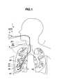
- FIG. 1 is a schematic diagram showing how a target site 9G at a bronchial end is biopsied by passing an insertion portion 4E of a treatment instrument 4 through a channel 2F1 of an endoscope 2A of an endoscope apparatus 2 inserted into a bronchus 9 of a patient 7.
- the bronchi 9 have multiple bifurcations. Therefore, to insert the treatment instrument 4 to the target site 9G, a surgeon needs to make a correct selection judgment and perform a proper insertion operation at each bifurcation based on an endoscopic image picked up by a CCD 2G (see Fig. 2 ) which is image pickup means in an insertion-portion distal end portion 2C of the endoscope 2A.
- a CCD 2G see Fig. 2
- a CMOS or the like may be used as the image pickup means.
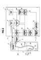
- the medical apparatus 1 in addition to the endoscope apparatus 2 and the treatment instrument 4, the medical apparatus 1 includes an insertion aid apparatus 3 adapted to aid the surgeon in making judgments and performing operations. That is, a first function of the insertion aid apparatus 3 is to help the surgeon make selection judgments at bifurcations. A second function of the insertion aid apparatus 3 is to help the surgeon perform bending operation.
- the endoscope apparatus 2 includes the insertion-portion distal end portion 2C, a bending portion 2D used for bending operation of the insertion-portion distal end portion 2C, an insertion portion 2E elongated in shape, and an operation portion 2B (see Fig. 2 ), which are installed consecutively.
- the treatment instrument 4 serving as treatment means includes a distal end portion 4C, a bending portion 4D used for bending operation of the distal end portion 4C, an insertion portion 4E elongated in shape, and an operation portion 4B (see Fig. 2 ), which are installed consecutively.
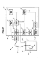
- the insertion aid apparatus 3 includes a CT image data storing unit 13, an input unit 14, a virtual endoscopic image generating unit 12 serving as virtual endoscopic image generating means (hereinafter the virtual endoscopic image will also be referred to as a "VBS image" which stands for Virtual Bronchus Scope image), an image processing unit 10, a display unit 6, a sensor 19 disposed in the distal end portion 4C of the treatment instrument 4, a magnetic field generating antenna 20, an antenna drive unit 21, a position detecting unit 22, a position storage unit 22B, and a control unit 11 which performs overall control.
- the components of the insertion aid apparatus 3 may be common with components (not shown) of the endoscope apparatus 2 which perform various processes.
- the CT image data storing unit 13 serving as storage means is a semiconductor storage device, a magnetic recording device, or the like which stores three-dimensional image data, for example, in DICOM (Digital Imaging and Communication in Medicine) format by receiving the three-dimensional image data via a receiving unit (not shown) as the three-dimensional image data is generated by a known CT apparatus (not shown) which picks up X-ray tomograms of the patient 7.
- DICOM Digital Imaging and Communication in Medicine
- the input unit 14 includes a keyboard, a mouse, and the like used by the surgeon to input information to the medical apparatus 1. In setting the position of the target site 9G based on three-dimensional image data, the surgeon also uses the input unit 14 serving as target position setting means.
- the VBS image generating unit 12 generates VBS images from the three-dimensional image data in DICOM format based on a six-dimensional line-of-sight parameter described later.
- the image processing unit 10 serving as image processing means performs image processing on endoscopic images (hereinafter also referred to as "real images") picked up by the CCD 2G as well as performs processing to display operation information, rotating operation information about the bending portion 4D, and a VBS image in superimposition as described later, where the operation information, the rotating operation information, and the VBS image are used to help insert the distal end portion 4C to the target site 9G.
- the display unit 6 serves as display means which displays real images, VBS images, and the like.
- the treatment instrument 4 has the sensor 19 in the distal end portion 4C to detect a position, a direction, and a roll angle (hereinafter also referred to as the "position and the like").
- the sensor 19 is, for example, a magnetic field detection sensor and is adapted to detect a magnetic field generated by the magnetic field generating antenna 20 made up of three antennas disposed outside the patient 7 and thereby detect position and the like where the treatment instrument 4 is disposed.
- an MR sensor, a Hall element, a coil, or the like may be used as the magnetic field detection sensor.
- ac magnetic fields of different frequencies are generated from multiple antennas of the magnetic field generating antenna 20 by the antenna drive unit 21.
- the sensor 19 detects the multiple ac magnetic fields of different frequencies in distinction from one another, allowing the position detecting unit 22 to detect information about the position, direction, and roll angle (X, Y, Z, a, e, r) of the sensor 19 with respect to the magnetic field generating antenna 20 based on information from the sensor 19, where (X, Y, Z) are three-dimensional coordinate values, (a) is an azimuth angle, (e) is an elevation angle, and (r) is a roll angle.
- a predetermined location of the treatment instrument 4, e.g., position of a distal end 4H is calculated based on the position of the sensor 19.
- the position storage unit 22B time-sequentially stores the position of the distal end 4H and the like detected by the position detecting unit 22.
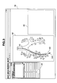
- a display screen 6a of the display unit 6 displays information 6A including information about the patient 7 and information about bifurcations of the bronchi 9, a virtual image 6B of the bronchi 9 based on three-dimensional image data, and a VBS image B (6C) and the like whose details are not illustrated.
- the VBS image B is a VBS image based on the line-of-sight parameter of the CCD 2G.
- the line-of-sight parameter is a six-dimensional parameter which includes the position, direction, and roll angle (X, Y, Z, a, e, r).
- a VBS image A is a VBS image based on the line-of-sight parameter of the distal end portion 4C of the treatment instrument 4.
- the surgeon By operating the input unit 14, the surgeon sets target site 9G of the lungs, which is a target position, with a pointer 14A or the like using the virtual image 6B. Incidentally, the surgeon may set any site such as a passing point along the way rather than the target site 9G.
- the insertion aid apparatus 3 calculates an insertion route R1, and displays the insertion route R1 in superimposition on the virtual image 6B as shown in Fig. 3 .
- the insertion route R1 is a core line leading to the target site 9G out of core lines which link center-of-gravity points or center points of lumen cross sections of the virtual endoscopic images.
- the VBS image generating unit 12 creates a VBS image B for each of the multiple bifurcations along the insertion route R1.
- the insertion aid apparatus 3 may have a VBS image storage unit (not shown) adapted to store VBS images of the bronchi 9 generated beforehand by the VBS image generating unit 12, and may display VBS images of the bifurcations along the insertion route R1 by extracting them from the stored VBS images.
- the display screen 6a displays a real image 6F picked up by the CCD 2G and processed by the image processing unit 10, multiple thumbnail VBS images (6E) which are reduced VBS images of the bifurcations appearing in the course of the insertion operation, and a VBS image B (6D) of the bifurcation which will appear next.
- the VBS image B (6D) is superimposed with guiding information 6G indicating which of the lumens located ahead of the bifurcation to insert the distal end portion into.
- the treatment instrument 4 does not need to be passed through the channel 2F1 in the insertion portion 2E.
- the treatment instrument 4 may be passed through the channel 2F1 of the insertion portion 2E with the distal end portion 4C fixed to a predetermined position of the insertion-portion distal end portion 2C of the insertion portion 2E.
- the surgeon cannot insert the insertion-portion distal end portion 2C of the endoscope 2A to the target site 9G even if the insertion portion 2E of the endoscope 2A has a thin diameter.
- the surgeon has to insert the distal end portion 4C of the treatment instrument 4 into the target site 9G in a deeper part by protruding the treatment instrument 4 from a treatment instrument outlet 2F of the insertion-portion distal end portion 2C of the endoscope 2A and carry out predetermined treatment there.
- the insertion portion 2E of the endoscope 2A has a diameter of, for example, 3 mm, which is smaller than a gastrointestinal endoscope or the like, but the treatment instrument 4 has a diameter of, for example, 1 mm so as to be able to be inserted into a still thinner peripheral lumen. Therefore, the bending portion 4D of the treatment instrument 4 is bendable only either in an up/down direction or a left/right direction. That is, unlike gastrointestinal endoscopes, the bending portion 4D cannot be bend freely in all four directions: left, right, up, and down. Consequently, the bending operation of the bending portion 4D requires skills.
- the phrase "up/down direction or left/right direction" is used for the sake of convenience, the phrase means one direction in a plane orthogonal to an insertion direction.
- the VBS image generating unit 12 of the insertion aid apparatus 3 generates the VBS image A based on the line-of-sight parameter of the distal end portion 4C, more precisely, part of the distal end portion 4C, for example, the distal end 4H, of the treatment instrument 4.
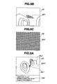
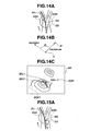
- the treatment instrument 4 includes the sensor 19 adapted to detect the position and the like. Consequently, the VBS image generating unit 12 generates the VBS image A based on the line-of-sight parameter, which in turn is based on the position and the like detected by the sensor 19, and displays the VBS image A in the display unit 6. Furthermore, the image processing unit 10 causes the display unit 6 to display an image ( Fig. 5C ) resulting from a superimposition process in which the VBS image A ( Fig. 5A ) is superimposed with a graphically displayed operations guide image 30 ( Fig. 5B ) intended to direct the distal end portion to a lumen 31 into which it should be inserted. As shown in Fig.
- the graphically displayed operations guide image 30, which is displayed as an arrow, for example, is not simply an image which indicates an insertion direction. That is, direction of the arrow represents a roll angle ⁇ 1 and length of the arrow represents a bending angle ⁇ 2.
- digital information may be displayed in addition to the graphic display.
- the surgeon can operate the operation portion 4B and perform a rotating operation. Then, by rotating the treatment instrument 4 by a roll angle ⁇ 1 as shown in Fig. 6B and then by bending the bending portion 4D by a bending angle ⁇ 2 as shown in Fig. 6C using the operation portion 4B, the surgeon can easily orient the distal end portion 4C to a lumen in the direction of the target site 9G.
- the surgeon rotates the bending portion 4D and the distal end portion 4C via the insertion portion 4E by griping and rotating the treatment instrument 4 on the side of a proximal end portion.
- the insertion aid apparatus 3 allows the surgeon to bring the distal end portion 4C to the target site 9G by watching the VBS image A and making selection judgments at bifurcations based on the guiding information of the VBS image A. Furthermore, even if the bending portion 4D cannot be bend freely in all four directions, the insertion aid apparatus 3 allows the surgeon to operate the bending portion 4D easily based on the operation information displayed by being superimposed on the VBS image A.
- the image processing unit 10 may perform a superimposition process and thereby display an insertion route 30L1 used to insert the distal end portion 4C to the target site 9G in superimposition on the VBS image A.
- Fig. 7A shows a case in which a transparent image 9GV1 of the target site 9G exists in a screen, where an insertion route 30L2 represented by a broken line is a non-visible insertion route which cannot be seen directly from the position of the distal end portion 4C.
- Fig. 7B shows a case in which no transparent image 9GV1 of the target site 9G exists in the screen of the VBS image A.
- Fig. 7B also illustrates something offscreen that is not displayed in the screen of the VBS image A.
- the insertion aid apparatus 3 performs a superimposition process and thereby displays the VBS image superimposed with insertion routes, the insertion route 30L1 visible from the position of the distal end portion 4C and the non-visible insertion route 30L2, to the target site 9G from the position of the distal end portion 4C which is being inserted.
- the insertion aid apparatus 3 provides excellent operability.
- the surgeon can insert the distal end portion 4C precisely to the target site 9G in a short time. Also, since the medical apparatus 1 does not use X-rays, the patient does not get exposed to radiation.
- Fig. 6C and the like show an example in which the image processing unit 10 performs a superimposition process and thereby displays the VBS image A in superimposition with the transparent image 9GV1 of the target site 9G.
- the target site 9G displayed here is located in such a position as not to be viewable using the currently set line-of-sight parameter, but displayed as the transparent image 9GV1 to provide position information about the target site 9G to the surgeon.
- the transparent image 9GV1 is represented by a broken line or displayed in a distinctive color so as to be easily distinguished from viewable sites.
- information about distance from the target site 9G can be provided to the surgeon using graphic display.
- the image 9GV of the target site 9G is set to be colored or hatched particularly conspicuously.
- the information of a predetermined size to be attached to the transparent image 9GV1 may have a fixed size to provide intuitive information about the distance from the target site 9G to the surgeon.
- the surgeon is allowed to set a predetermined size for a target position i.e., to set the volume of the target site 9G, via the input unit 14.
- the image processing unit 10 can perform a superimposition process and thereby display the volume of the target site 9G, length of the insertion route from the current position of the distal end portion 4C to the target site 9G, and the number of bifurcations N on the insertion route in superimposition.
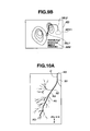
- Fig. 9A and 9B when the volume of the target site 9G is set, the image processing unit 10 can perform a superimposition process and thereby display the volume of the target site 9G, length of the insertion route from the current position of the distal end portion 4C to the target site 9G, and the number of bifurcations N on the insertion route in superimposition.
- Fig. 9A is an example in which operation information is displayed below the VBS image A in superimposition while Fig. 9B is an example in which operation information is displayed in the VBS image A in superimposition.
- the insertion aid apparatus described above can convey more information to the surgeon, and thus provides more excellent operability. That is, although three-dimensional display such as the virtual image 6B in Fig. 3 is not provided, the surgeon can obtain information about approximate distance to the target site 9G.
- the image processing unit 10 may perform a superimposition process of operation information only when bending operation or rotating operation is necessary. That is, when the distal end portion 4C is passing through a non-bifurcated lumen before reaching a bifurcation or when the distal end portion 4C is oriented in a correct insertion direction, there is no need to provide operation information to the surgeon.
- the image processing unit 10 performs a superimposition process for display of operation information only when the distal end portion 4C reaches a predetermined operation information display area and a predetermined bending angle threshold and a predetermined roll angle threshold are reached.
- the image processing unit 10 displays operation information in superimposition only for bending operation or rotating operation whichever needs to be performed. That is, the image processing unit 10 performs a superimposition process of the operation information when at least either of bending operation and rotating operation is required.
- the image processing unit 10 which displays operation information in superimposition based on the bending angle threshold and the roll angle threshold provides good operability because unnecessary information is not presented to the surgeon.
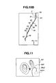
- the operation information display area is a region of the bronchi in a predetermined three-dimensional space with reference to bifurcations N1 to NX of the insertion route R1, for example, in a sphere SX of a predetermined radius from the bifurcation NX That is, as described later, even after the distal end portion 4C passes a bifurcation, preferably operation information is displayed as long as the distal end portion 4C is located in the operation information display area. This is to display a recovery method or the like in case the distal end portion 4C is inserted into a lumen in a wrong direction due to misoperation or the like, as described later.
- the position of the distal end portion 4C is calculated based on the position of the sensor 19.
- the radius of the sphere SX which provides the operation information display area is equal to or longer than a device tip length L, but may vary with the position of the bifurcation N, where the device tip length L is the length of the bending portion 4D used for bending operation of the distal end portion 4C.
- the image processing unit 10 of the insertion aid apparatus 3 can alert the surgeon by presenting a special display, for example, by displaying an X mark such as shown in Fig. 11 in addition to the superimposed display of the insertion route.
- the position of the distal end 4H will be defined as point B, a fulcrum for bending of the bending portion 4D as point A, and a starting point of the bending portion 4D on the side of the proximal end portion as point O.
- the insertion aid apparatus 3 calculates positions of point A, point B, and point O based on time-series data on the position of the distal end 4H stored in the position storage unit 22B.
- the image processing unit 10 does not display the bending angle ⁇ 2 and the roll angle ⁇ 1 as operation information.
- the image processing unit 10 does not perform a superimposition process of the bending angle ⁇ 2 or the roll angle ⁇ 1.
- information that the distal end portion 4C is oriented in the correct insertion direction may be displayed as text information 30M.
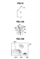
- a vector V is derived from a tangent to the insertion direction at a bifurcation of the insertion route, to begin with.
- a vector AB is derived from position information about point A and point B or from a distal end direction vector at point A.
- a vector OA is derived and a plane OAV perpendicular to the vector OA is defined.
- the bending angle ⁇ 2 is calculated. That is, a circle centered at point A and having a radius equal to the device tip length L is created such that a point of intersection with the area in the insertion route direction on a plane OAB will be point B2. Then, as shown in Fig. 15B , an angle between the vector AB and a vector AB2 is the bending angle ⁇ 2. Consequently, as shown in Fig. 15C , the roll angle ⁇ 1 and the bending angle ⁇ 2 are displayed by being superimposed on the VBS image A.
- operating direction is displayed to inform the surgeon of rotating direction or bending direction.
- the operation information may be displayed either in text form as shown in Figs. 18A and 18B or in graphic form shown in Figs. 18C and 18D .
- the graphic display shown in Fig. 18(C) and the like is superimposed on a virtual endoscopic image.
- the second function of the insertion aid apparatus 3 is to aid the bending operation of the bending portion 4D of the treatment instrument 4, but the second function can also be used to aid the bending operation of the bending portion 2D of the endoscope 2A. That is, during insertion operation of the insertion portion 2E, if the distal end portion 4C of the treatment instrument 4 is inserted into the channel 2F1 in advance, the sensor 19 can be placed in a predetermined position of the insertion-portion distal end portion 2C.
- the insertion aid apparatus 3 can graphically display bending operation information about the bending portion 2D in superimposition on the VBS image B to the surgeon.
- the insertion aid apparatus 3 may be configured to perform a process to display the bending operation information in superimposition on a real image.
- a virtual image of the treatment instrument 4 may be displayed in the display unit 6, being superimposed on a VBS image C whose line-of-sight parameter is viewable from the treatment instrument 4.
- the insertion aid apparatus 3 calculates the shortest route as the insertion route.
- multiple insertion routes may be displayed simultaneously when selected by the surgeon.
- the next shortest insertion route may be displayed when, for example, a "2nd ROUTE" (next candidate display) button 6P presented in the display unit 6 of a touch panel type is pressed or selected by an operator.
- the "2nd ROUTE" button may be a dedicated mechanical button.
- the insertion routes are displayed in different colors, line shapes, or the like.
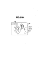
- the distal end portion 4C is located in a lumen off the insertion route (first insertion route) due to a wrong operation, there are cases where the distal end portion 4C can reach the target site 9G through another insertion route (second insertion route). In that case, as shown in Fig. 21A , the "2nd ROUTE" button is automatically displayed in the display unit 6.
- the insertion aid apparatus described above calculates multiple insertion routes, allowing the surgeon to select the most suitable insertion route at the time even during an insertion operation, and thus provides good operability.
- the medical apparatus 1A according to the present embodiment is similar to the medical apparatus 1 according to the first embodiment, and the same components as those in the first embodiment are denoted by the same reference numerals as the corresponding components, and description thereof will be omitted.
- an insertion aid apparatus 3A of the medical apparatus 1A includes a correction unit 23 adapted to correct the position and the like detected by the sensor 19, based on a real image picked up by the CCD 2G.
- the control unit 11 can cause the VBS image generating unit 12 to generate a VBS image B similar to a real image photographed by the CCD 2G. That is, based on the position, direction, and roll angle (X0, Y0, Z0, a0, e0, r0) of the sensor 19 detected by the sensor 19, first the control unit 11 generates a VBS image B whose line-of-sight parameter includes the position, direction, and roll angle (X1, Y1, Z1, a1, e1, r1) of the CCD 2G at the time. Then, the control unit 11 compares similarity between the VBS image B and the real image.
- the similarity of images is checked by known image processing, which may use either matching at a pixel data level or matching at the level of features extracted from the images.
- the matching process of the real image and the VBS image B is performed per frame of the real image, and an actual comparison process is carried out with reference to similarity between a static endoscopic image and the VBS image B.
- the control unit 11 If the comparison and calculation of similarity between the real image and the VBS image B reveals a larger error e between the two images than an allowable error e0 (No), the control unit 11 outputs the line-of-sight parameter whose values have been changed slightly to the VBS image generating unit 12.
- the VBS image generating unit 12 generates a next VBS image B based on the new line-of-sight parameter.
- the VBS image B generated by the VBS image generating unit 12 gradually becomes more similar to the real image, and after a few iterations, the error e between the two images becomes smaller than the allowable error e0.
- the control unit 11 detects the line-of-sight parameter of the CCD 2G, in other words, the position, direction, and roll angle (Xn, Yn, Zn, an, en, rn) of the CCD 2G, equal to or smaller than the allowable error e0 in real image information.
- the correction unit 23 uses the line-of-sight parameter to correct the position, direction, and roll angle (X0, Y0, Z0, a0, e0, r0) of the sensor 19 detected by the sensor 19, based on the position, direction, and roll angle (Xn, Yn, Zn, an, en, rn) of the CCD 2G.
- control unit 11 calibrates the sensor 19 based on a second virtual endoscopic image B and the real image, where the second virtual endoscopic image B has the line-of-sight parameter which is made up of the position, the direction, and the roll angle of the CCD 2G.
- the surgeon has a clearer view of a relative relationship between the distal end 4H of the treatment instrument 4 and the target site 9G.
- the position of the target site 9G has been set by the input unit 14 in a CT coordinate system which is based on three-dimensional image data.
- the position of the sensor 19 is obtained in a sensor coordinate system relative to, for example, the magnetic field generating antenna 20.
- a correction process performed by the correction unit 23 is intended not only to correct detection errors of the sensor 19, but also to ensure consistency between the CT coordinate system and the sensor coordinate system, in other words, calculate a coordinate transformation formula between the different coordinate systems.
- the coordinate transformation formula calculated by the correction unit 23 allows the control unit 11 to perform control more accurately and easily.
- the medical apparatus 1A features higher processing speed and enables highly accurate navigation, and thus allows the distal end portion 4C of the treatment instrument 4 to be inserted to the target site 9G in a lumen more reliably.
- the medical apparatus 1B according to the present variation is similar to the medical apparatus 1A according to the second embodiment, and the same components as those in the second embodiment are denoted by the same reference numerals as the corresponding components, and description thereof will be omitted.
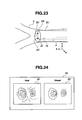
- a correction unit 23B of an insertion aid apparatus 3B of the medical apparatus 1B includes a correction unit 23B adapted to correct the position and the like detected by the sensor 19, based on an image of the treatment instrument 4 contained in a real image picked up by the CCD 2G of the endoscope 2A.
- the surgeon protrudes the distal end portion 4C of the treatment instrument 4 from the treatment instrument outlet 2F of the insertion-portion distal end portion 2C.
- This provides a real image which shows the distal end portion 4C being picked up, as shown in Fig. 26 .
- the treatment instrument 4 has a graduated scale 4L which allows an amount of protrusion and the like to be detected and a graduated scale 4M which allows rotation to be detected.
- the graduated scales can be read from the real image by the control unit 11. Based on the read data and the like, the control unit 11 can calculates a relative positional relationship between the distal end 4H of the treatment instrument 4 and the CCD 2G.
- the control unit 11 corrects the information detected by the sensor 19 to improve accuracy of the information, and in other words, calibrates the information from the sensor 19.
- the medical apparatus 1B enables more accurate navigation, and thus allows the distal end portion 4C of the treatment instrument 4 to be inserted to the target site 9G in a lumen more reliably.
- a medical apparatus 1C according to a third embodiment is similar to the medical apparatus 1 according to the first embodiment, and the same components as those in the first embodiment are denoted by the same reference numerals as the corresponding components, and description thereof will be omitted.
- the medical apparatus 1C includes a treatment instrument 4 inserted alone into the bronchus 9 of the patient and a reference marker 24 placed on a body surface of the patient 7.
- the medical apparatus 1C can ensure consistency between the CT coordinate system and the sensor coordinate system, and in other words, calculate a coordinate transformation formula between the different coordinate systems.
- the treatment instrument 4 cannot acquire endoscopic images of bifurcations during insertion operation.
- the surgeon can insert the distal end portion 4C to the target site 9G based on the VBS image A and operations guide image 30 displayed by an insertion aid apparatus 3C of the medical apparatus 1C.
- Movements of the insertion aid apparatus 3C of the medical apparatus 1C are the same as movements carried out to aid the treatment instrument 4 in the medical apparatus 1.
- the medical apparatus 1C according to the present embodiment provides the same advantages as the medical apparatus 1 according to the first embodiment.
- the medical apparatus includes: a treatment instrument inserted in a channel of an endoscope so as to protrude from an endoscopic distal end portion, equipped with a sensor and a bending portion in a distal end portion, and inserted to a target site in a bronchus, where the sensor is intended to detect a position, a direction, and a roll angle; an image data storing unit adapted to store three-dimensional image data of the bronchus acquired in advance; an input unit used to set the target site; a virtual endoscopic image generating unit adapted to generate a virtual endoscopic image using a line-of-sight parameter which includes the position, the direction, and the roll angle of the distal end portion detected by the sensor, based on the three-dimensional image data; an image processing unit adapted to perform a superimposition process and thereby display bending operation information of the bending portion, rotating operation information of the distal end portion, the virtual endoscopic image, and an insertion route in superimposition with one another to help
Claims (12)
- Medizinisches Gerät, das umfasst:einen endoskopischen Einführabschnitt (4E), der mit einem Bildaufnahmemittel (2G) und einem Kanal (2F1) versehen ist, der durch ein inneres Teil hindurchtritt;ein Behandlungsmittel (4), das mit einem Sensor (19) und einem Biegeabschnitt (4D) versehen ist und durch den Kanal (2F1) hindurchtritt, wobei es einem distalen Endabschnitt (4C) des Behandlungsmittels (4) möglich ist, von einem distalen Einführabschnitt-Endabschnitt (2C) des endoskopischen Einführabschnitts (4E) vorzustehen, wobei der Sensor (19) in dem distalen Endabschnitt (4C) angeordnet und dazu eingerichtet ist, eine Position, eine Richtung und einen Rollwinkel zu erfassen, und der Biegeabschnitt (4D) dazu eingerichtet ist, den distalen Endabschnitt (4C) zu biegen;ein Speichermittel (13), das dazu eingerichtet ist, vorab aufgenommene dreidimensionale Bilddaten des Lumens eines Subjekts zu speichern;ein Zielpositionsfestlegungsmittel (14), das dazu eingerichtet ist, die Zielposition auf der Basis der dreidimensionalen Bilddaten festzulegen; undein Mittel (12) zur Erzeugung eines virtuellen endoskopischen Bilds, das dazu eingerichtet ist, ein virtuelles endoskopisches Bild zu erzeugen, indem es einen Sichtlinienparameter verwendet, der die Position, die Richtung und den Rollwinkel des distalen Endabschnitts (4C) umfasst, die durch den Sensor (19) auf der Basis der dreidimensionalen Bilddaten erfasst worden sind, und wobeider Biegeabschnitt (4D) entweder in einer aufwärts/abwärts-Richtung oder einer links/rechts-Richtung biegbar ist,gekennzeichnet durchein Bildverarbeitungsmittel (10), das dazu eingerichtet ist, einen Überlagerungsprozess durchzuführen und dadurch eine Operationsinformation, die zum Einführen des distalen Endabschnitts (4C) zu der Zielposition verwendet wird, dem virtuellen endoskopischen Bild überlagert anzuzeigen, wobeidie von dem Bildverarbeitungsmittel (10) verarbeitete Operationsinformation eine Information über einen Biegewinkel des Biegeabschnitts (4D) und einen Rollwinkel des distalen Endabschnitts (4C) ist.
- Medizinisches Gerät nach Anspruch 1, bei dem das Lumen eine Mehrzahl von Verzweigungen hat.
- Medizinisches Gerät (1) nach Anspruch 1, bei dem das Bildverarbeitungsmittel (10) ferner einen Überlagerungsprozess einer Einführroute durchführt, die zum Einführen des distalen Endabschnitts (4C) zu der vorbestimmten Position verwendet wird.
- Medizinisches Gerät nach Anspruch 3, bei dem, wenn eine Mehrzahl der Einführrouten vorhanden ist, das Bildverarbeitungsmittel (10) einen Überlagerungsprozess durchführt und dadurch alle der Mehrzahl von Einführrouten oder eine ausgewählte der Einführrouten anzeigt.
- Medizinisches Gerät nach Anspruch 3, bei dem:das Zielpositionsfestlegungsmittel (14) dazu in der Lage ist, einen Zielort, der ein vorbestimmtes Volumen hat, als die Zielposition festzulegen;das Bildverarbeitungsmittel (10) einen Überlagerungsprozess durchführt und dadurch das vorbestimmte Volumen des Zielorts, eine Länge der Einführroute von dem distalen Endabschnitt (4C) zu dem Zielort und eine Anzahl von Verzweigungen auf der Einführroute von dem distalen Endabschnitt (4C) zu dem Zielort einander überlagert anzeigt.
- Medizinisches Gerät nach Anspruch 1, das ferner ein Korrekturmittel (23) umfasst, das dazu eingerichtet ist, eine Position, eine Richtung und einen Rollwinkel, die von dem Sensor (19) auf der Basis eines von dem Bildaufnahmemittel (2G) aufgenommenen endoskopischen Bilds und eines zweiten virtuellen endoskopischen Bilds, das einen eine Position, eine Richtung und einen Rollwinkel des Bildaufnahmemittels (2G) umfassenden Sichtlinienparameter hat, erfasst worden sind, zu korrigieren und eine Koordinatentransformationsformel zu berechnen, die dazu verwendet wird, Koordinaten der von dem Sensor (19) erfassten Position in ein Koordinatensystem der dreidimensionalen Bilddaten zu transformieren.
- Medizinisches Gerät nach Anspruch 6, bei dem das endoskopische Bild ein Bild ist, bei dem der distale Endabschnitt (4C), der von dem distalen Einführabschnitt-Endabschnitt (2C) vorsteht, aufgenommen wird.
- Medizinisches Gerät nach Anspruch 6, bei dem eine Position des distalen Endabschnitts (4C), der von dem distalen Einführabschnitt-Endabschnitt (2C) vorsteht, an einem Ort angeordnet ist, in den der distale Einführabschnitt-Endabschnitt (2C) nicht einführbar ist.
- Medizinisches Gerät nach Anspruch 1, bei dem das Lumen eine Bronchie ist.
- Medizinisches Gerät nach Anspruch 1, bei dem das Bildverarbeitungsmittel (10) einen Überlagerungsprozess durchführt und dadurch die Operationsinformation anzeigt, wann eine Biegeoperation des Biegeabschnitts (4D) und/oder eine Drehoperation des distalen Endabschnitts (4C) erforderlich ist.
- Medizinisches Gerät nach Anspruch 1, bei dem das Bildverarbeitungsmittel (10) bestimmt, ob die Biegeoperation oder die dritte Operation erforderlich ist oder nicht, indem es den Biegewinkel und den Rollwinkel, die die Operationsinformation bereitstellen, mit jeweiligen vorbestimmten Schwellwerten vergleicht.
- Medizinisches Gerät nach Anspruch 1, bei dem die Operationsinformation, die durch das Bildverarbeitungsmittel (10) verarbeitet wird, grafisch dargestellt wird.
Applications Claiming Priority (2)
| Application Number | Priority Date | Filing Date | Title |
|---|---|---|---|
| JP2010036480 | 2010-02-22 | ||
| PCT/JP2010/065324 WO2011102012A1 (ja) | 2010-02-22 | 2010-09-07 | 医療機器 |
Publications (3)
| Publication Number | Publication Date |
|---|---|
| EP2377457A1 EP2377457A1 (de) | 2011-10-19 |
| EP2377457A4 EP2377457A4 (de) | 2013-01-09 |
| EP2377457B1 true EP2377457B1 (de) | 2016-07-27 |
Family
ID=44482627
Family Applications (1)
| Application Number | Title | Priority Date | Filing Date |
|---|---|---|---|
| EP10827686.6A Active EP2377457B1 (de) | 2010-02-22 | 2010-09-07 | Medizinische vorrichtung |
Country Status (4)
| Country | Link |
|---|---|
| US (1) | US8102416B2 (de) |
| EP (1) | EP2377457B1 (de) |
| CN (1) | CN102740755B (de) |
| WO (1) | WO2011102012A1 (de) |
Families Citing this family (104)
| Publication number | Priority date | Publication date | Assignee | Title |
|---|---|---|---|---|
| EP3492008B1 (de) | 2005-09-13 | 2021-06-02 | Veran Medical Technologies, Inc. | Vorrichtung und verfahren zur bildgelenkten präzisionsprüfung |
| US20070066881A1 (en) | 2005-09-13 | 2007-03-22 | Edwards Jerome R | Apparatus and method for image guided accuracy verification |
| US10004387B2 (en) * | 2009-03-26 | 2018-06-26 | Intuitive Surgical Operations, Inc. | Method and system for assisting an operator in endoscopic navigation |
| US8337397B2 (en) | 2009-03-26 | 2012-12-25 | Intuitive Surgical Operations, Inc. | Method and system for providing visual guidance to an operator for steering a tip of an endoscopic device toward one or more landmarks in a patient |
| US9962229B2 (en) | 2009-10-12 | 2018-05-08 | Corindus, Inc. | System and method for navigating a guide wire |
| WO2011094518A2 (en) * | 2010-01-28 | 2011-08-04 | The Penn State Research Foundation | Image-based global registration system and method applicable to bronchoscopy guidance |
| WO2011161564A1 (en) * | 2010-06-22 | 2011-12-29 | Koninklijke Philips Electronics N.V. | System and method for real-time endoscope calibration |
| US8672837B2 (en) | 2010-06-24 | 2014-03-18 | Hansen Medical, Inc. | Methods and devices for controlling a shapeable medical device |
| US20120071753A1 (en) | 2010-08-20 | 2012-03-22 | Mark Hunter | Apparatus and method for four dimensional soft tissue navigation including endoscopic mapping |
| JP5766940B2 (ja) * | 2010-12-01 | 2015-08-19 | オリンパス株式会社 | 管状挿入システム |
| US8900131B2 (en) * | 2011-05-13 | 2014-12-02 | Intuitive Surgical Operations, Inc. | Medical system providing dynamic registration of a model of an anatomical structure for image-guided surgery |
| EP4056111A3 (de) | 2012-02-22 | 2022-12-07 | Veran Medical Technologies, Inc. | Systeme, verfahren und vorrichtungen für vierdimensionale weichgewebenavigation |
| JP2013202313A (ja) * | 2012-03-29 | 2013-10-07 | Panasonic Corp | 手術支援装置および手術支援プログラム |
| JP5807826B2 (ja) * | 2012-03-29 | 2015-11-10 | パナソニックヘルスケア株式会社 | 手術支援装置および手術支援プログラム |
| US10299698B2 (en) | 2012-05-14 | 2019-05-28 | Intuitive Surgical Operations, Inc. | Systems and methods for registration of a medical device using a reduced search space |
| US10039473B2 (en) | 2012-05-14 | 2018-08-07 | Intuitive Surgical Operations, Inc. | Systems and methods for navigation based on ordered sensor records |
| CN103648395B (zh) * | 2012-06-07 | 2017-07-28 | 松下知识产权经营株式会社 | 转矩测定装置 |
| JP2013252387A (ja) * | 2012-06-08 | 2013-12-19 | Canon Inc | 医療用画像処理装置 |
| JP2014028125A (ja) * | 2012-06-29 | 2014-02-13 | Toshiba Corp | 超音波診断装置及び制御プログラム |
| US9259269B2 (en) | 2012-08-07 | 2016-02-16 | Covidien Lp | Microwave ablation catheter and method of utilizing the same |
| EP2884879B1 (de) * | 2012-08-14 | 2020-01-08 | Intuitive Surgical Operations, Inc. | Systeme und verfahren zur registrierung mehrerer sichtsysteme |
| US20140188440A1 (en) | 2012-12-31 | 2014-07-03 | Intuitive Surgical Operations, Inc. | Systems And Methods For Interventional Procedure Planning |
| JP6233913B2 (ja) * | 2013-01-07 | 2017-11-22 | 晃 竹林 | 内視鏡向けナビゲーション装置 |
| WO2014141968A1 (ja) * | 2013-03-12 | 2014-09-18 | オリンパスメディカルシステムズ株式会社 | 内視鏡システム |
| US9057600B2 (en) | 2013-03-13 | 2015-06-16 | Hansen Medical, Inc. | Reducing incremental measurement sensor error |
| US9639666B2 (en) | 2013-03-15 | 2017-05-02 | Covidien Lp | Pathway planning system and method |
| US9271663B2 (en) | 2013-03-15 | 2016-03-01 | Hansen Medical, Inc. | Flexible instrument localization from both remote and elongation sensors |
| US9925009B2 (en) * | 2013-03-15 | 2018-03-27 | Covidien Lp | Pathway planning system and method |
| US9629595B2 (en) | 2013-03-15 | 2017-04-25 | Hansen Medical, Inc. | Systems and methods for localizing, tracking and/or controlling medical instruments |
| US9014851B2 (en) | 2013-03-15 | 2015-04-21 | Hansen Medical, Inc. | Systems and methods for tracking robotically controlled medical instruments |
| US9439570B2 (en) * | 2013-03-15 | 2016-09-13 | Lx Medical Corporation | Tissue imaging and image guidance in luminal anatomic structures and body cavities |
| US9364167B2 (en) | 2013-03-15 | 2016-06-14 | Lx Medical Corporation | Tissue imaging and image guidance in luminal anatomic structures and body cavities |
| CN104755009B (zh) * | 2013-04-15 | 2017-04-19 | 奥林巴斯株式会社 | 内窥镜系统 |
| CN103169445B (zh) * | 2013-04-16 | 2016-07-06 | 苏州朗开医疗技术有限公司 | 一种内窥镜的导航方法及系统 |
| US11020016B2 (en) | 2013-05-30 | 2021-06-01 | Auris Health, Inc. | System and method for displaying anatomy and devices on a movable display |
| WO2014203847A1 (ja) * | 2013-06-18 | 2014-12-24 | オリンパスメディカルシステムズ株式会社 | 挿入装置 |
| CN109954196B (zh) * | 2013-08-15 | 2021-11-09 | 直观外科手术操作公司 | 用于导管定位和插入的图形用户界面 |
| JP2017502728A (ja) | 2013-12-09 | 2017-01-26 | インテュイティブ サージカル オペレーションズ, インコーポレイテッド | 装置を認識する可撓性ツール位置合わせのためのシステム及び方法 |
| WO2015118423A1 (en) | 2014-02-04 | 2015-08-13 | Koninklijke Philips N.V. | Visualization of depth and position of blood vessels and robot guided visualization of blood vessel cross section |
| EP3119325B2 (de) * | 2014-03-17 | 2022-04-13 | Intuitive Surgical Operations, Inc. | Systeme und verfahren zur steuerung der ausrichtung eines bildgebungsinstruments |
| JP6854237B2 (ja) * | 2014-03-28 | 2021-04-07 | インテュイティブ サージカル オペレーションズ, インコーポレイテッド | 視野内の器具の定量的三次元視覚化 |
| US20150305650A1 (en) | 2014-04-23 | 2015-10-29 | Mark Hunter | Apparatuses and methods for endobronchial navigation to and confirmation of the location of a target tissue and percutaneous interception of the target tissue |
| US20150305612A1 (en) | 2014-04-23 | 2015-10-29 | Mark Hunter | Apparatuses and methods for registering a real-time image feed from an imaging device to a steerable catheter |
| JP6534193B2 (ja) | 2014-07-02 | 2019-06-26 | コヴィディエン リミテッド パートナーシップ | 実時間自動位置合わせフィードバック |
| CN111449669B (zh) | 2014-07-02 | 2023-04-18 | 柯惠有限合伙公司 | 用于检测气管的系统和方法 |
| US9603668B2 (en) | 2014-07-02 | 2017-03-28 | Covidien Lp | Dynamic 3D lung map view for tool navigation inside the lung |
| US9770216B2 (en) | 2014-07-02 | 2017-09-26 | Covidien Lp | System and method for navigating within the lung |
| US9754367B2 (en) | 2014-07-02 | 2017-09-05 | Covidien Lp | Trachea marking |
| US9836848B2 (en) | 2014-07-02 | 2017-12-05 | Covidien Lp | System and method for segmentation of lung |
| CN106659374B (zh) * | 2014-07-02 | 2021-04-02 | 柯惠有限合伙公司 | 在3d导航时提供距离和取向反馈的系统和方法 |
| CA2953694A1 (en) * | 2014-07-02 | 2016-01-07 | Covidien Lp | Alignment ct |
| US20160000414A1 (en) | 2014-07-02 | 2016-01-07 | Covidien Lp | Methods for marking biopsy location |
| CN107106119A (zh) | 2014-10-30 | 2017-08-29 | 皇家飞利浦有限公司 | 弯曲结构的超声可视化 |
| CN106464827B (zh) * | 2014-11-27 | 2019-10-01 | 奥林巴斯株式会社 | 图像再现装置和图像再现方法 |
| CN111494008A (zh) | 2014-12-05 | 2020-08-07 | 科林达斯公司 | 用于引导导线的系统和方法 |
| WO2016098255A1 (ja) * | 2014-12-19 | 2016-06-23 | オリンパス株式会社 | 挿抜支援装置及び挿抜支援方法 |
| JP6356623B2 (ja) * | 2015-03-18 | 2018-07-11 | 富士フイルム株式会社 | 画像処理装置、方法、及びプログラム |
| JP6371729B2 (ja) * | 2015-03-25 | 2018-08-08 | 富士フイルム株式会社 | 内視鏡検査支援装置、内視鏡検査支援装置の作動方法および内視鏡支援プログラム |
| US9892506B2 (en) * | 2015-05-28 | 2018-02-13 | The Florida International University Board Of Trustees | Systems and methods for shape analysis using landmark-driven quasiconformal mapping |
| US10163262B2 (en) * | 2015-06-19 | 2018-12-25 | Covidien Lp | Systems and methods for navigating through airways in a virtual bronchoscopy view |
| WO2016207973A1 (ja) * | 2015-06-23 | 2016-12-29 | オリンパス株式会社 | 内視鏡システム、内視鏡情報処理装置および内視鏡情報処理方法 |
| JP6594133B2 (ja) | 2015-09-16 | 2019-10-23 | 富士フイルム株式会社 | 内視鏡位置特定装置、内視鏡位置特定装置の作動方法および内視鏡位置特定プログラム |
| US9727963B2 (en) | 2015-09-18 | 2017-08-08 | Auris Surgical Robotics, Inc. | Navigation of tubular networks |
| US10986990B2 (en) | 2015-09-24 | 2021-04-27 | Covidien Lp | Marker placement |
| US10709352B2 (en) | 2015-10-27 | 2020-07-14 | Covidien Lp | Method of using lung airway carina locations to improve ENB registration |
| US10143526B2 (en) | 2015-11-30 | 2018-12-04 | Auris Health, Inc. | Robot-assisted driving systems and methods |
| US10478254B2 (en) | 2016-05-16 | 2019-11-19 | Covidien Lp | System and method to access lung tissue |
| CN113951799A (zh) * | 2016-06-01 | 2022-01-21 | 恩达马斯特有限公司 | 内窥镜对接站 |
| EP4238490A3 (de) | 2016-06-30 | 2023-11-01 | Intuitive Surgical Operations, Inc. | Grafische benutzeroberfläche zur anzeige von anleitungsinformationen während eines bildgeführten verfahrens |
| US10244926B2 (en) | 2016-12-28 | 2019-04-02 | Auris Health, Inc. | Detecting endolumenal buckling of flexible instruments |
| CN106890025B (zh) * | 2017-03-03 | 2020-02-28 | 浙江大学 | 一种微创手术导航系统和导航方法 |
| JP6745748B2 (ja) * | 2017-03-16 | 2020-08-26 | 富士フイルム株式会社 | 内視鏡位置特定装置、その作動方法およびプログラム |
| KR102558061B1 (ko) | 2017-03-31 | 2023-07-25 | 아우리스 헬스, 인코포레이티드 | 생리적 노이즈를 보상하는 관강내 조직망 항행을 위한 로봇 시스템 |
| CN110621252B (zh) * | 2017-04-18 | 2024-03-15 | 直观外科手术操作公司 | 用于监测图像引导程序的图形用户界面 |
| US10022192B1 (en) | 2017-06-23 | 2018-07-17 | Auris Health, Inc. | Automatically-initialized robotic systems for navigation of luminal networks |
| EP3644885B1 (de) | 2017-06-28 | 2023-10-11 | Auris Health, Inc. | Ausrichtung eines elektromagnetischen feldgenerators |
| WO2019005696A1 (en) | 2017-06-28 | 2019-01-03 | Auris Health, Inc. | DETECTION OF ELECTROMAGNETIC DISTORTION |
| US10506991B2 (en) * | 2017-08-31 | 2019-12-17 | Biosense Webster (Israel) Ltd. | Displaying position and optical axis of an endoscope in an anatomical image |
| FR3071396B1 (fr) * | 2017-09-22 | 2022-01-21 | Koelis | Dispositif de guidage d’instrument medical et procede correspondant |
| US10464209B2 (en) * | 2017-10-05 | 2019-11-05 | Auris Health, Inc. | Robotic system with indication of boundary for robotic arm |
| US10555778B2 (en) | 2017-10-13 | 2020-02-11 | Auris Health, Inc. | Image-based branch detection and mapping for navigation |
| US11058493B2 (en) | 2017-10-13 | 2021-07-13 | Auris Health, Inc. | Robotic system configured for navigation path tracing |
| US11219489B2 (en) | 2017-10-31 | 2022-01-11 | Covidien Lp | Devices and systems for providing sensors in parallel with medical tools |
| JP6749020B2 (ja) * | 2017-11-29 | 2020-09-02 | 水野 裕子 | 内視鏡ナビゲーション装置 |
| WO2019107226A1 (ja) * | 2017-11-29 | 2019-06-06 | 水野 裕子 | 内視鏡装置 |
| JP2019097665A (ja) * | 2017-11-29 | 2019-06-24 | 水野 裕子 | 内視鏡装置 |
| KR20200100613A (ko) | 2017-12-14 | 2020-08-26 | 아우리스 헬스, 인코포레이티드 | 기구 위치 추정을 위한 시스템 및 방법 |
| CN110809453B (zh) | 2017-12-18 | 2023-06-06 | 奥瑞斯健康公司 | 用于腔网络内的器械跟踪和导航的方法和系统 |
| WO2019130390A1 (ja) * | 2017-12-25 | 2019-07-04 | オリンパス株式会社 | 推奨操作呈示システム、推奨操作呈示制御装置及び推奨操作呈示制御方法 |
| US11224392B2 (en) | 2018-02-01 | 2022-01-18 | Covidien Lp | Mapping disease spread |
| US11464576B2 (en) | 2018-02-09 | 2022-10-11 | Covidien Lp | System and method for displaying an alignment CT |
| US10524866B2 (en) | 2018-03-28 | 2020-01-07 | Auris Health, Inc. | Systems and methods for registration of location sensors |
| US10827913B2 (en) | 2018-03-28 | 2020-11-10 | Auris Health, Inc. | Systems and methods for displaying estimated location of instrument |
| US10905499B2 (en) | 2018-05-30 | 2021-02-02 | Auris Health, Inc. | Systems and methods for location sensor-based branch prediction |
| EP3801280A4 (de) | 2018-05-31 | 2022-03-09 | Auris Health, Inc. | Robotersysteme und verfahren zur navigation eines luminalen netzwerks zur detektion physiologischer geräusche |
| WO2019231891A1 (en) | 2018-05-31 | 2019-12-05 | Auris Health, Inc. | Path-based navigation of tubular networks |
| MX2020012904A (es) | 2018-05-31 | 2021-02-26 | Auris Health Inc | Analisis y mapeo de vias respiratorias basados en imagen. |
| CN114340540B (zh) | 2019-08-30 | 2023-07-04 | 奥瑞斯健康公司 | 器械图像可靠性系统和方法 |
| CN114340542B (zh) | 2019-08-30 | 2023-07-21 | 奥瑞斯健康公司 | 用于位置传感器的基于权重的配准的系统和方法 |
| EP4025921A4 (de) | 2019-09-03 | 2023-09-06 | Auris Health, Inc. | Detektion und kompensation von elektromagnetischer verzerrung |
| US20220198742A1 (en) * | 2019-09-20 | 2022-06-23 | Hoya Corporation | Processor for endoscope, program, information processing method, and information processing device |
| JP2023508525A (ja) | 2019-12-31 | 2023-03-02 | オーリス ヘルス インコーポレイテッド | 経皮的アクセスのための位置合わせ技術 |
| CN114929148A (zh) | 2019-12-31 | 2022-08-19 | 奥瑞斯健康公司 | 用于经皮进入的对准界面 |
| WO2021137072A1 (en) | 2019-12-31 | 2021-07-08 | Auris Health, Inc. | Anatomical feature identification and targeting |
Family Cites Families (17)
| Publication number | Priority date | Publication date | Assignee | Title |
|---|---|---|---|---|
| US5840024A (en) * | 1993-10-18 | 1998-11-24 | Olympus Optical Co., Ltd. | Endoscope form detecting apparatus in which coil is fixedly mounted by insulating member so that form is not deformed within endoscope |
| JP2002119507A (ja) | 2000-10-17 | 2002-04-23 | Toshiba Corp | 医用装置および医用画像収集表示方法 |
| JP2002306403A (ja) | 2001-04-18 | 2002-10-22 | Olympus Optical Co Ltd | 内視鏡装置 |
| ES2865048T3 (es) * | 2002-04-17 | 2021-10-14 | Covidien Lp | Estructuras de endoscopio para navegar a un objetivo en una estructura ramificada |
| JP4009639B2 (ja) * | 2002-07-31 | 2007-11-21 | オリンパス株式会社 | 内視鏡装置、内視鏡装置のナビゲーション方法、内視鏡画像の表示方法、及び内視鏡用画像表示プログラム |
| JP4436638B2 (ja) * | 2002-08-30 | 2010-03-24 | オリンパス株式会社 | 内視鏡装置及び内視鏡挿入動作プログラム |
| AU2003264354A1 (en) | 2002-08-30 | 2004-04-30 | Olympus Corporation | Medical treatment system, endoscope system, endoscope insert operation program, and endoscope device |
| JP4245880B2 (ja) * | 2002-08-30 | 2009-04-02 | オリンパス株式会社 | 内視鏡装置 |
| JP4698966B2 (ja) * | 2004-03-29 | 2011-06-08 | オリンパス株式会社 | 手技支援システム |
| US7835785B2 (en) * | 2005-10-04 | 2010-11-16 | Ascension Technology Corporation | DC magnetic-based position and orientation monitoring system for tracking medical instruments |
| WO2007074668A1 (ja) * | 2005-12-26 | 2007-07-05 | Hrs Consultant Service, Inc. | 心エコー診断教育装置 |
| US8199984B2 (en) * | 2006-05-02 | 2012-06-12 | National University Corporation Nagoya University | System that assists in observing a luminal organ using the structure of the luminal organ |
| WO2008111070A2 (en) * | 2007-03-12 | 2008-09-18 | David Tolkowsky | Devices and methods for performing medical procedures in tree-like luminal structures |
| JP5123615B2 (ja) * | 2007-08-31 | 2013-01-23 | オリンパスメディカルシステムズ株式会社 | 内視鏡挿入支援装置 |
| JP4922107B2 (ja) * | 2007-09-03 | 2012-04-25 | オリンパスメディカルシステムズ株式会社 | 内視鏡装置 |
| JP5028191B2 (ja) | 2007-09-03 | 2012-09-19 | オリンパスメディカルシステムズ株式会社 | 内視鏡装置 |
| JP2010036480A (ja) | 2008-08-06 | 2010-02-18 | Reiko Co Ltd | 箔こぼれ防止転写フイルム |
-
2010
- 2010-09-07 WO PCT/JP2010/065324 patent/WO2011102012A1/ja active Application Filing
- 2010-09-07 CN CN201080003294.3A patent/CN102740755B/zh active Active
- 2010-09-07 EP EP10827686.6A patent/EP2377457B1/de active Active
-
2011
- 2011-02-09 US US13/023,806 patent/US8102416B2/en active Active
Also Published As
| Publication number | Publication date |
|---|---|
| WO2011102012A1 (ja) | 2011-08-25 |
| US8102416B2 (en) | 2012-01-24 |
| CN102740755B (zh) | 2015-04-22 |
| EP2377457A4 (de) | 2013-01-09 |
| EP2377457A1 (de) | 2011-10-19 |
| US20110234780A1 (en) | 2011-09-29 |
| CN102740755A (zh) | 2012-10-17 |
Similar Documents
| Publication | Publication Date | Title |
|---|---|---|
| EP2377457B1 (de) | Medizinische vorrichtung | |
| US20230346487A1 (en) | Graphical user interface for monitoring an image-guided procedure | |
| EP2581029B1 (de) | Medizinische vorrichtung | |
| CN108430373B (zh) | 用于在患者体内跟踪内窥镜的位置的装置和方法 | |
| US20190362552A1 (en) | Controlled perspective guidance method | |
| EP1761160B1 (de) | System und verfahren für die bildbasierte ausrichtung eines endoskops | |
| EP1924197B1 (de) | System für flexible navigierte endoskopie | |
| JP5146692B2 (ja) | 光学的位置測定ならびに剛性または半可撓性の針の標的への誘導のためのシステム | |
| US7824328B2 (en) | Method and apparatus for tracking a surgical instrument during surgery | |
| JP2017528175A (ja) | 3dのナビゲーションの間に距離および向きのフィードバックを提供するシステムおよび方法 | |
| JP2009279249A (ja) | 医療機器 | |
| JP2009279250A (ja) | 医療機器 | |
| JP4728456B1 (ja) | 医療機器 | |
| WO2008107874A2 (en) | Method, system and computer product for planning needle procedures | |
| US20230363635A1 (en) | Endoscopic anatomical feature tracking | |
| US20220354380A1 (en) | Endoscope navigation system with updating anatomy model | |
| US20230143522A1 (en) | Surgical assistant system based on image data of the operative field | |
| EP4333682A1 (de) | Endoskopnavigationssystem mit aktualisierungsanatomiemodell | |
| WO2023235224A1 (en) | Systems and methods for robotic endoscope with integrated tool-in-lesion-tomosynthesis |
Legal Events
| Date | Code | Title | Description |
|---|---|---|---|
| PUAI | Public reference made under article 153(3) epc to a published international application that has entered the european phase |
Free format text: ORIGINAL CODE: 0009012 |
|
| 17P | Request for examination filed |
Effective date: 20110503 |
|
| AK | Designated contracting states |
Kind code of ref document: A1 Designated state(s): AL AT BE BG CH CY CZ DE DK EE ES FI FR GB GR HR HU IE IS IT LI LT LU LV MC MK MT NL NO PL PT RO SE SI SK SM TR |
|
| A4 | Supplementary search report drawn up and despatched |
Effective date: 20121206 |
|
| RIC1 | Information provided on ipc code assigned before grant |
Ipc: A61B 1/04 20060101ALI20121130BHEP Ipc: A61B 19/00 20060101ALI20121130BHEP Ipc: A61B 1/00 20060101AFI20121130BHEP Ipc: A61B 1/267 20060101ALI20121130BHEP |
|
| DAX | Request for extension of the european patent (deleted) | ||
| RAP1 | Party data changed (applicant data changed or rights of an application transferred) |
Owner name: OLYMPUS CORPORATION |
|
| GRAP | Despatch of communication of intention to grant a patent |
Free format text: ORIGINAL CODE: EPIDOSNIGR1 |
|
| RIC1 | Information provided on ipc code assigned before grant |
Ipc: A61B 1/04 20060101ALI20160111BHEP Ipc: A61B 1/00 20060101AFI20160111BHEP Ipc: A61B 1/267 20060101ALI20160111BHEP |
|
| INTG | Intention to grant announced |
Effective date: 20160205 |
|
| GRAS | Grant fee paid |
Free format text: ORIGINAL CODE: EPIDOSNIGR3 |
|
| GRAA | (expected) grant |
Free format text: ORIGINAL CODE: 0009210 |
|
| AK | Designated contracting states |
Kind code of ref document: B1 Designated state(s): AL AT BE BG CH CY CZ DE DK EE ES FI FR GB GR HR HU IE IS IT LI LT LU LV MC MK MT NL NO PL PT RO SE SI SK SM TR |
|
| RAP1 | Party data changed (applicant data changed or rights of an application transferred) |
Owner name: OLYMPUS CORPORATION |
|
| REG | Reference to a national code |
Ref country code: GB Ref legal event code: FG4D |
|
| REG | Reference to a national code |
Ref country code: CH Ref legal event code: EP |
|
| REG | Reference to a national code |
Ref country code: AT Ref legal event code: REF Ref document number: 815097 Country of ref document: AT Kind code of ref document: T Effective date: 20160815 |
|
| REG | Reference to a national code |
Ref country code: IE Ref legal event code: FG4D |
|
| REG | Reference to a national code |
Ref country code: DE Ref legal event code: R096 Ref document number: 602010035110 Country of ref document: DE |
|
| RAP2 | Party data changed (patent owner data changed or rights of a patent transferred) |
Owner name: OLYMPUS CORPORATION |
|
| RAP2 | Party data changed (patent owner data changed or rights of a patent transferred) |
Owner name: OLYMPUS CORPORATION |
|
| RIN2 | Information on inventor provided after grant (corrected) |
Inventor name: ITO, SEIICHI Inventor name: ONISHI, JUNICHI |
|
| REG | Reference to a national code |
Ref country code: LT Ref legal event code: MG4D |
|
| REG | Reference to a national code |
Ref country code: NL Ref legal event code: MP Effective date: 20160727 |
|
| REG | Reference to a national code |
Ref country code: AT Ref legal event code: MK05 Ref document number: 815097 Country of ref document: AT Kind code of ref document: T Effective date: 20160727 |
|
| PG25 | Lapsed in a contracting state [announced via postgrant information from national office to epo] |
Ref country code: NL Free format text: LAPSE BECAUSE OF FAILURE TO SUBMIT A TRANSLATION OF THE DESCRIPTION OR TO PAY THE FEE WITHIN THE PRESCRIBED TIME-LIMIT Effective date: 20160727 Ref country code: FI Free format text: LAPSE BECAUSE OF FAILURE TO SUBMIT A TRANSLATION OF THE DESCRIPTION OR TO PAY THE FEE WITHIN THE PRESCRIBED TIME-LIMIT Effective date: 20160727 Ref country code: LT Free format text: LAPSE BECAUSE OF FAILURE TO SUBMIT A TRANSLATION OF THE DESCRIPTION OR TO PAY THE FEE WITHIN THE PRESCRIBED TIME-LIMIT Effective date: 20160727 Ref country code: NO Free format text: LAPSE BECAUSE OF FAILURE TO SUBMIT A TRANSLATION OF THE DESCRIPTION OR TO PAY THE FEE WITHIN THE PRESCRIBED TIME-LIMIT Effective date: 20161027 Ref country code: IS Free format text: LAPSE BECAUSE OF FAILURE TO SUBMIT A TRANSLATION OF THE DESCRIPTION OR TO PAY THE FEE WITHIN THE PRESCRIBED TIME-LIMIT Effective date: 20161127 Ref country code: HR Free format text: LAPSE BECAUSE OF FAILURE TO SUBMIT A TRANSLATION OF THE DESCRIPTION OR TO PAY THE FEE WITHIN THE PRESCRIBED TIME-LIMIT Effective date: 20160727 Ref country code: IT Free format text: LAPSE BECAUSE OF FAILURE TO SUBMIT A TRANSLATION OF THE DESCRIPTION OR TO PAY THE FEE WITHIN THE PRESCRIBED TIME-LIMIT Effective date: 20160727 |
|
| PG25 | Lapsed in a contracting state [announced via postgrant information from national office to epo] |
Ref country code: BE Free format text: LAPSE BECAUSE OF NON-PAYMENT OF DUE FEES Effective date: 20160727 Ref country code: SE Free format text: LAPSE BECAUSE OF FAILURE TO SUBMIT A TRANSLATION OF THE DESCRIPTION OR TO PAY THE FEE WITHIN THE PRESCRIBED TIME-LIMIT Effective date: 20160727 Ref country code: LV Free format text: LAPSE BECAUSE OF FAILURE TO SUBMIT A TRANSLATION OF THE DESCRIPTION OR TO PAY THE FEE WITHIN THE PRESCRIBED TIME-LIMIT Effective date: 20160727 Ref country code: AT Free format text: LAPSE BECAUSE OF FAILURE TO SUBMIT A TRANSLATION OF THE DESCRIPTION OR TO PAY THE FEE WITHIN THE PRESCRIBED TIME-LIMIT Effective date: 20160727 Ref country code: GR Free format text: LAPSE BECAUSE OF FAILURE TO SUBMIT A TRANSLATION OF THE DESCRIPTION OR TO PAY THE FEE WITHIN THE PRESCRIBED TIME-LIMIT Effective date: 20161028 Ref country code: PT Free format text: LAPSE BECAUSE OF FAILURE TO SUBMIT A TRANSLATION OF THE DESCRIPTION OR TO PAY THE FEE WITHIN THE PRESCRIBED TIME-LIMIT Effective date: 20161128 Ref country code: PL Free format text: LAPSE BECAUSE OF FAILURE TO SUBMIT A TRANSLATION OF THE DESCRIPTION OR TO PAY THE FEE WITHIN THE PRESCRIBED TIME-LIMIT Effective date: 20160727 Ref country code: ES Free format text: LAPSE BECAUSE OF FAILURE TO SUBMIT A TRANSLATION OF THE DESCRIPTION OR TO PAY THE FEE WITHIN THE PRESCRIBED TIME-LIMIT Effective date: 20160727 |
|
| PG25 | Lapsed in a contracting state [announced via postgrant information from national office to epo] |
Ref country code: MC Free format text: LAPSE BECAUSE OF FAILURE TO SUBMIT A TRANSLATION OF THE DESCRIPTION OR TO PAY THE FEE WITHIN THE PRESCRIBED TIME-LIMIT Effective date: 20160727 Ref country code: RO Free format text: LAPSE BECAUSE OF FAILURE TO SUBMIT A TRANSLATION OF THE DESCRIPTION OR TO PAY THE FEE WITHIN THE PRESCRIBED TIME-LIMIT Effective date: 20160727 Ref country code: EE Free format text: LAPSE BECAUSE OF FAILURE TO SUBMIT A TRANSLATION OF THE DESCRIPTION OR TO PAY THE FEE WITHIN THE PRESCRIBED TIME-LIMIT Effective date: 20160727 |
|
| REG | Reference to a national code |
Ref country code: CH Ref legal event code: PL |
|
| REG | Reference to a national code |
Ref country code: DE Ref legal event code: R097 Ref document number: 602010035110 Country of ref document: DE |
|
| PG25 | Lapsed in a contracting state [announced via postgrant information from national office to epo] |
Ref country code: SK Free format text: LAPSE BECAUSE OF FAILURE TO SUBMIT A TRANSLATION OF THE DESCRIPTION OR TO PAY THE FEE WITHIN THE PRESCRIBED TIME-LIMIT Effective date: 20160727 Ref country code: DK Free format text: LAPSE BECAUSE OF FAILURE TO SUBMIT A TRANSLATION OF THE DESCRIPTION OR TO PAY THE FEE WITHIN THE PRESCRIBED TIME-LIMIT Effective date: 20160727 Ref country code: BG Free format text: LAPSE BECAUSE OF FAILURE TO SUBMIT A TRANSLATION OF THE DESCRIPTION OR TO PAY THE FEE WITHIN THE PRESCRIBED TIME-LIMIT Effective date: 20161027 Ref country code: SM Free format text: LAPSE BECAUSE OF FAILURE TO SUBMIT A TRANSLATION OF THE DESCRIPTION OR TO PAY THE FEE WITHIN THE PRESCRIBED TIME-LIMIT Effective date: 20160727 Ref country code: CZ Free format text: LAPSE BECAUSE OF FAILURE TO SUBMIT A TRANSLATION OF THE DESCRIPTION OR TO PAY THE FEE WITHIN THE PRESCRIBED TIME-LIMIT Effective date: 20160727 |
|
| PLBE | No opposition filed within time limit |
Free format text: ORIGINAL CODE: 0009261 |
|
| STAA | Information on the status of an ep patent application or granted ep patent |
Free format text: STATUS: NO OPPOSITION FILED WITHIN TIME LIMIT |
|
| GBPC | Gb: european patent ceased through non-payment of renewal fee |
Effective date: 20161027 |
|
| REG | Reference to a national code |
Ref country code: IE Ref legal event code: MM4A |
|
| REG | Reference to a national code |
Ref country code: FR Ref legal event code: ST Effective date: 20170531 |
|
| 26N | No opposition filed |
Effective date: 20170502 |
|
| PG25 | Lapsed in a contracting state [announced via postgrant information from national office to epo] |
Ref country code: CH Free format text: LAPSE BECAUSE OF NON-PAYMENT OF DUE FEES Effective date: 20160930 Ref country code: GB Free format text: LAPSE BECAUSE OF NON-PAYMENT OF DUE FEES Effective date: 20161027 Ref country code: FR Free format text: LAPSE BECAUSE OF NON-PAYMENT OF DUE FEES Effective date: 20160930 Ref country code: LI Free format text: LAPSE BECAUSE OF NON-PAYMENT OF DUE FEES Effective date: 20160930 Ref country code: IE Free format text: LAPSE BECAUSE OF NON-PAYMENT OF DUE FEES Effective date: 20160907 |
|
| PG25 | Lapsed in a contracting state [announced via postgrant information from national office to epo] |
Ref country code: LU Free format text: LAPSE BECAUSE OF NON-PAYMENT OF DUE FEES Effective date: 20160907 Ref country code: SI Free format text: LAPSE BECAUSE OF FAILURE TO SUBMIT A TRANSLATION OF THE DESCRIPTION OR TO PAY THE FEE WITHIN THE PRESCRIBED TIME-LIMIT Effective date: 20160727 |
|
| PG25 | Lapsed in a contracting state [announced via postgrant information from national office to epo] |
Ref country code: CY Free format text: LAPSE BECAUSE OF FAILURE TO SUBMIT A TRANSLATION OF THE DESCRIPTION OR TO PAY THE FEE WITHIN THE PRESCRIBED TIME-LIMIT Effective date: 20160727 Ref country code: HU Free format text: LAPSE BECAUSE OF FAILURE TO SUBMIT A TRANSLATION OF THE DESCRIPTION OR TO PAY THE FEE WITHIN THE PRESCRIBED TIME-LIMIT; INVALID AB INITIO Effective date: 20100907 |
|
| PG25 | Lapsed in a contracting state [announced via postgrant information from national office to epo] |
Ref country code: MT Free format text: LAPSE BECAUSE OF NON-PAYMENT OF DUE FEES Effective date: 20160930 Ref country code: MK Free format text: LAPSE BECAUSE OF FAILURE TO SUBMIT A TRANSLATION OF THE DESCRIPTION OR TO PAY THE FEE WITHIN THE PRESCRIBED TIME-LIMIT Effective date: 20160727 Ref country code: TR Free format text: LAPSE BECAUSE OF FAILURE TO SUBMIT A TRANSLATION OF THE DESCRIPTION OR TO PAY THE FEE WITHIN THE PRESCRIBED TIME-LIMIT Effective date: 20160727 |
|
| PG25 | Lapsed in a contracting state [announced via postgrant information from national office to epo] |
Ref country code: AL Free format text: LAPSE BECAUSE OF FAILURE TO SUBMIT A TRANSLATION OF THE DESCRIPTION OR TO PAY THE FEE WITHIN THE PRESCRIBED TIME-LIMIT Effective date: 20160727 |
|
| P01 | Opt-out of the competence of the unified patent court (upc) registered |
Effective date: 20230528 |
|
| PGFP | Annual fee paid to national office [announced via postgrant information from national office to epo] |
Ref country code: DE Payment date: 20230920 Year of fee payment: 14 |