EP2377213B1 - Flexible ignitor assembly for air/fuel mixture and method of construction thereof - Google Patents
Flexible ignitor assembly for air/fuel mixture and method of construction thereof Download PDFInfo
- Publication number
- EP2377213B1 EP2377213B1 EP10729648.5A EP10729648A EP2377213B1 EP 2377213 B1 EP2377213 B1 EP 2377213B1 EP 10729648 A EP10729648 A EP 10729648A EP 2377213 B1 EP2377213 B1 EP 2377213B1
- Authority
- EP
- European Patent Office
- Prior art keywords
- electrical connector
- housing
- subassembly
- electrical
- terminal
- Prior art date
- Legal status (The legal status is an assumption and is not a legal conclusion. Google has not performed a legal analysis and makes no representation as to the accuracy of the status listed.)
- Active
Links
Images


Classifications
-
- H—ELECTRICITY
- H01—ELECTRIC ELEMENTS
- H01T—SPARK GAPS; OVERVOLTAGE ARRESTERS USING SPARK GAPS; SPARKING PLUGS; CORONA DEVICES; GENERATING IONS TO BE INTRODUCED INTO NON-ENCLOSED GASES
- H01T13/00—Sparking plugs
- H01T13/02—Details
-
- H—ELECTRICITY
- H01—ELECTRIC ELEMENTS
- H01T—SPARK GAPS; OVERVOLTAGE ARRESTERS USING SPARK GAPS; SPARKING PLUGS; CORONA DEVICES; GENERATING IONS TO BE INTRODUCED INTO NON-ENCLOSED GASES
- H01T13/00—Sparking plugs
- H01T13/02—Details
- H01T13/04—Means providing electrical connection to sparking plugs
-
- H—ELECTRICITY
- H01—ELECTRIC ELEMENTS
- H01T—SPARK GAPS; OVERVOLTAGE ARRESTERS USING SPARK GAPS; SPARKING PLUGS; CORONA DEVICES; GENERATING IONS TO BE INTRODUCED INTO NON-ENCLOSED GASES
- H01T13/00—Sparking plugs
- H01T13/20—Sparking plugs characterised by features of the electrodes or insulation
-
- H—ELECTRICITY
- H01—ELECTRIC ELEMENTS
- H01T—SPARK GAPS; OVERVOLTAGE ARRESTERS USING SPARK GAPS; SPARKING PLUGS; CORONA DEVICES; GENERATING IONS TO BE INTRODUCED INTO NON-ENCLOSED GASES
- H01T13/00—Sparking plugs
- H01T13/40—Sparking plugs structurally combined with other devices
- H01T13/44—Sparking plugs structurally combined with other devices with transformers, e.g. for high-frequency ignition
-
- Y—GENERAL TAGGING OF NEW TECHNOLOGICAL DEVELOPMENTS; GENERAL TAGGING OF CROSS-SECTIONAL TECHNOLOGIES SPANNING OVER SEVERAL SECTIONS OF THE IPC; TECHNICAL SUBJECTS COVERED BY FORMER USPC CROSS-REFERENCE ART COLLECTIONS [XRACs] AND DIGESTS
- Y10—TECHNICAL SUBJECTS COVERED BY FORMER USPC
- Y10T—TECHNICAL SUBJECTS COVERED BY FORMER US CLASSIFICATION
- Y10T29/00—Metal working
- Y10T29/49—Method of mechanical manufacture
- Y10T29/49002—Electrical device making
-
- Y—GENERAL TAGGING OF NEW TECHNOLOGICAL DEVELOPMENTS; GENERAL TAGGING OF CROSS-SECTIONAL TECHNOLOGIES SPANNING OVER SEVERAL SECTIONS OF THE IPC; TECHNICAL SUBJECTS COVERED BY FORMER USPC CROSS-REFERENCE ART COLLECTIONS [XRACs] AND DIGESTS
- Y10—TECHNICAL SUBJECTS COVERED BY FORMER USPC
- Y10T—TECHNICAL SUBJECTS COVERED BY FORMER US CLASSIFICATION
- Y10T29/00—Metal working
- Y10T29/49—Method of mechanical manufacture
- Y10T29/49826—Assembling or joining
- Y10T29/49904—Assembling a subassembly, then assembling with a second subassembly
Definitions
- This invention relates generally to ignitors used for igniting air/fuel mixtures in automotive application and the like.
- US Patent 6,883,507 discloses an ignitor for use in a corona discharge air/fuel ignition system.
- the ignitor is straight and is able to fit in ignitor openings that are straight. However, it is not able to accommodate a non-straight and/or a partially obstructed ignitor opening.
- An ignitor capable of accommodating a non-straight and/or partially obstructed ignitor opening is known from US 2008/0271724 A1
- An ignitor assembly constructed in accordance with one aspect of the invention has an upper inductor subassembly including a tubular housing extending between an upper end and a lower end with inductor windings received therein and an upper electrical connector adjacent the upper end of the housing and a lower electrical connector adjacent the lower end of the housing.
- the upper electrical connector is configured in electrical communication with the lower electrical connector via the inductor windings.
- the ignitor assembly also has a lower firing end subassembly including a ceramic insulator and a metal housing surrounding at least a portion of the ceramic insulator.
- the ceramic insulator extends between a terminal end and a firing end with an electrical terminal extending from the terminal end in electrical contact with the lower electrical connector of the upper inductor subassembly.
- An electrode extends from the firing end of the ceramic insulator and is configured in electrical communication with the electrical terminal.
- the ignitor assembly further has a non-metal tube connecting the upper inductor subassembly to the lower firing end subassembly.
- the non-metal tube maintains the electrical terminal in electrical contact with the lower electrical connector.
- the non-metal tube has an intermediate region extending between the tubular housing of the upper inductor subassembly and the ceramic insulator. The intermediate region is circumferentially unconstrained from allowing relative pivotal movement between the electrical terminal and the lower electrical connector.
- the intermediate region allows the flexible ignitor assembly to be freely disposed in bent, multi-axis or partially obstructed ignitor holes in a cylinder head of an engine. Further, designers of the cylinder head and overall ignition systems are free to utilize less space and introduce complex, partially obstructed, or multi-axes bores, if necessary, to house the ignitor assembly without concern for accommodating installation of the ignitor assembly along a straight path.
- the efficient utilization of available space in a cylinder head and throughout the ignition system, as a result of the flexible ignitor assembly contributes to a decrease in the size, weight and cost of the overall engine.
- a method of constructing an ignitor assembly includes forming a lower firing end subassembly having a ceramic insulator and a metal housing surrounding at least a portion of the ceramic insulator with an electrical terminal extending from a terminal end of the insulator and an electrode extending from a firing end of the insulator. Further, forming an upper inductor subassembly having a tubular housing extending between an upper end and a lower end with inductor windings received in the housing and having an upper electrical connector adjacent the upper end and a lower electrical connector adjacent the lower end with the lower electrical connector being axially biased relative to the tubular housing by a spring member.
- FIGS 1-3 show an ignitor assembly, represented as a corona discharge ignitor assembly, and referred to hereafter as assembly 10, constructed in accordance with one aspect of the invention.
- the assembly 10 is constructed to be mounted within an ignitor bore 12 of a cylinder head 14 that is configured to be joined to an engine block 16 of an internal combustion engine 18.
- the engine block 16 includes a combustion cylinder 20 in which a piston (not shown) reciprocates.
- the engine 18 may have a plurality of such combustion cylinders 20 and associated pistons.
- the ignitor bore 12 can be constructed to extend along a straight axis, or, if desired, along multiple non-parallel axes, such as may be desired to route around other adjacent engine features, such as a fuel injector bore 19 in which a fuel injector head (not shown) is received for injecting a fuel/air mixture into the combustion cylinder 20 and/or a valve bore 21 in which a valve assembly 23 is received, for example.
- the assembly 10 is constructed to flex at a bend joint, also referred to as pivot joint 22, and thus, is able to freely attain a bent configuration, as needed and desired. Accordingly, the assembly 10 is able accommodate a curved and/or partially obstructed ignitor bore 12 and otherwise allows an upper inductor subassembly 24 to pivot relative to a lower firing end subassembly 26.
- the cylinder head 14 is formed with at least one of the ignition bores 12 associated with each combustion cylinder 20.
- the ignition bore 12 extends from an upper surface 28 of the head 14 to a lower surface 30 and is in open communication with the associated combustion cylinder 20.
- the bore 12 can extend along an axis A that is transverse or substantially transverse to the upper surface 28 or it can extend along an axis B that is inclined at an oblique angle to the upper surface 28, or both.
- the assembly 10 is able to accommodate an inclination between the axes A and B without impacting the functionality of the assembly 10.
- the ignition bore 12 may be positioned and routed immediately adjacent other features of the engine 18, such as a fuel injection bore, for example.
- the engine 18 has a cylinder head cover, also referred to as a valve cover 32, bolted or otherwise secured to the cylinder head 14.
- the cover 32 has an opening 34 to accommodate the ignitor assembly 10, such that an electrical wire or source of power can be readily attached to the ignitor assembly 10.
- the opening 34 can be positioned and centered along the axis B of the lower firing end subassembly 26, or it could be located off center from the axis B, such as along axis C, if desired.
- the opening 34 can be constructed as an integral cylindrical passage with the valve cover 32, as shown, or a it can be provided via a separate tubular sleeve for fixed and sealed receipt with an upper surface 38 of the valve cover 32 and being brought into sealed engagement with the upper surface 28 of the cylinder head 14.
- a separate tubular shield 39 can be disposed about a portion of the assembly 10 to facilitate protecting the assembly 10 from exposure to oil within the valve cover 32.
- the opening 34 or sleeve 36 provides a mechanism to fix the upper inductor subassembly 24 in position relative to the lower firing end subassembly 26 that is fixed in the bore 12 of cylinder head 14, and further, keeps the upper inductor subassembly 24 free from any undesired exposure to lubricant.
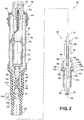
- the upper inductor subassembly 24 includes a metal tubular housing 40 that extends along a first axis A' between an upper end 42 and a lower end 44.
- the housing 40 is shown here as having an enlarged diameter upper portion 46 and a lower portion 48 that is reduced in diameter from the upper portion 46.
- the upper portion 46 is sized appropriately to receive the desired configuration of inductor windings, also referred to as a coil 50, of both high and low voltage inductor windings.
- the coil 50 is wound about a central ferromagnetic core 52 and is in electrical communication with an upper electrical connector 54 adjacent the upper end 42 of the housing 40 and a lower electrical connector 56 adjacent the lower end 44 of the housing 40.
- the housing 40 is either filled with a pressurized gas or resin 60 about the coil 50 and the housing 40 for high voltage suppression.
- the resin 60 fills or substantially fills any voids within the upper portion 46 of the housing 40.
- a polymeric or rubber cap 62 extends circumferentially about the upper end 42 of the housing 40 and is shown as having annular projections or ribs 64 extending radially outwardly from the housing 40 to facilitate fixing and forming a seal between the housing 40 and the cylinder head cover 32.
- the lower electrical connector 56 is constructed of a suitable conducting metal material and is sized having a cylindrical shape for close plunging movement within the lower portion 48 of the housing 40. Accordingly, the cylindrical lower electrical connector 56 has a slightly reduced outer diameter from the inner diameter of the lower portion 48, thereby providing a loose fit therebetween.
- the lower electrical connector 56 extends outwardly from the lower end 44 of the housing 40 to a free end 57 having a concave surface.
- An opposite end 59 of the connector 56 is brought into electrical communication with the coil 50 via a spring member 66 and an intermediate conductor 68.
- both the spring member 66 and the intermediate conductor 68 are constructed from a suitable metal material.
- the spring member 66 is represented here as being a coil spring member, though other spring configurations are contemplated to be within the scope of the invention.
- the intermediate conductor 68 is fixed to the coil 50, such as by way of interference fit within the lower portion 48 and/or via the resin 60.
- the spring member 66 has one end 70 configured in electrical communication with the intermediate conductor 68 and another end 72 configured in electrical communication with the lower electrical connector 56.
- the end 70 can be fixed to the intermediate conductor 68, such as by being attached or snapped over an end of the conductor 68 and the end 72 can be fixed to the lower electrical connector 56, such as by being attached or snapped over an end of the connector 56.
- the lower electrical connector 56 though able to slide freely in the lower portion 48 of the housing 40, can be held and maintained from falling freely out of the lower portion 48 by the spring member 66, if desired.
- the lower firing end subassembly 26 includes an elongate ceramic insulator 74 extending between an upper terminal end 76 and a lower firing end 78 with central through passage 80 extending therebetween.
- the insulator 74 has an enlarged diameter intermediate section 82 providing radially outwardly extending upper and lower shoulders 84, 86, respectively.
- the insulator 74 also has a tapered nose 88 converging to the firing end 78.
- An electrical terminal 90 is received within the central through passage 80 and extends from the terminal end 76 of the bore 56 to a free end 91, shown as being convex, for pivotal electrical communication with the lower electrical connector 56 of the upper inductor subassembly 24.
- a central electrode 92 is received within the central through passage 80 and extends from the firing end 78 to a free discharge end 94 which, when the ignitor assembly 10 is installed in the cylinder head 14, projects into the combustion cylinder 20 of the engine 18.
- the terminal 90 and the central electrode 92 are configured in electrical communication with one another, such as via a resistor layer 96 made from any suitable composition used in such applications to suppress electromagnetic interference ("EMI").
- EMI electromagnetic interference
- the lower firing end subassembly 26 further includes an outer metal jacket, also referred to as housing or shell 98.
- the shell 98 surrounds at least a portion of the ceramic insulator 74 in fixed relation thereto.
- the shell 98 has an inner surface 99 shaped to receive the insulator 74 therein with an inner shoulder 100 configured to abut the lower shoulder 86 of the insulator intermediate section 82 and an uppermost lip 102 that is curled, rolled, or otherwise folded over the upper shoulder 84 of the insulator intermediate section 82 to capture the intermediated section 82 between the shoulder 100 and the lip 102.
- the shell 98 may be provided with an external hexagonal tool receiving member 104 or other feature for removal and installation of the lower firing end subassembly 26 in the ignitor bore 12.
- the feature size will preferably conform with an industry standard tool size of this type for the related application. Of course, some applications may call for a tool receiving interface other than a hexagon, such as slots to receive a spanner wrench, or other features such as are known in racing spark plug and other applications.
- the shell 98 also has an annular flange 106 extending radially outwardly from an outer surface 101 of the shell 98 to provide an annular, generally planar sealing seat 108 from which a threaded region 110 depends.
- the sealing seat 108 may be paired with a gasket 112 to facilitate a hot gas seal of the space between the outer surface 101 of the shell 98 and the threaded bore in the ignitor bore 12.
- the sealing seat 108 may be configured as a tapered seat located along the lower portion of the shell 98 to provide a close tolerance and a self-sealing installation in a cylinder head which is also designed with a mating taper for this style of spark plug seat.
- the lower firing end subassembly 26 is connected to the upper inductor subassembly 24 by an intervening flexible tube 114, such as a non-metal tube of polymeric material, such as silicone, or other suitable types of rubber, for example.
- the tube 114 has an upper end 116 attached to the housing 40 of the upper inductor subassembly 24 and an opposite lower end 118 attached to the ceramic insulator 74 with an intermediate region 120 extending between the tubular housing 40 of the upper inductor subassembly 24 and the ceramic insulator 74.
- a through passage 122 extends axially between the ends 116, 118.
- the through passage 122 has a radially inwardly extending annular protrusion, also referred to as constriction 124, sized to restrict or inhibit the passage of the lower electrical connector 56 therethrough.
- the constriction 124 is located within the intermediate region 120 of the tube 114. As such, the constriction 124 facilitates maintaining the upper inductor subassembly 24 in an assembled state prior to attachment to the lower firing end subassembly 26 by maintaining the lower electrical connector 56 within the tube 114 against the bias imparted by the spring member 66.
- the intermediate region 120 is circumferentially unconstrained to allow relative pivotal movement between the electrical terminal 90 and the lower electrical connector 56.
- the lower firing end subassembly 26 is first threaded into the ignitor bore 12 of the cylinder head 14. While threading the threaded region 110 of the shell 98 into the ignitor bore 12, the sealing seat 108 is brought into sealed engagement with a sealing surface 126 in the ignitor bore 12. Then, upon fixing the lower firing end subassembly 26 into the ignitor bore 12, the upper inductor subassembly 24 is attached to the lower firing end subassembly 26, either prior to fastening the cylinder head cover 32 to the cylinder head 14 or after.
- the upper inductor subassembly 24 is disposed in the ignitor bore 12, thereby disposing the lower end 118 of the flexible tube 114 over the terminal end 76 of the insulator 74.
- the convex free end 91 of the terminal 90 is received through the constriction 124 of the tube 114 and brought into direct electrical contact with the concave free end 57 of the lower electrode connector 56.
- the lower electrode connector 56 is free to plunge axially against the bias of the spring member 66 to accommodate assembly of the upper inductor subassembly 24 to the lower firing end subassembly 26, and thus, moves axially out of engagement and away from the constriction 124 as necessary to complete the assembly.
- the convex free 91 and the concave free end 57 are radially aligned with the unconstrained intermediate region 120 of the tube 114 to form the pivot joint 22, wherein the pivot joint 22 is able to be freely pivoted, such as in a ball and socket type joint.
- the ignitor assembly 10 can be assembled and secured in position within the ignitor bore 12.
- the lower end of the jacket 54 can be threaded to allow the ignitor assembly 10 to be screwed into a blind threaded region of the ignitor bore 12, as discussed or the ignitor could be provided with suitable clamps and/or fasteners to enable the ignitor to be secured to the cylinder head 14 at or near its upper surface.
- the valve cover 32 can be installed either before or after installation of the ignitor assembly 10, depending upon the particular routing and fastening requirements. Accordingly, the particular fastening technique is less important to this invention and any of a number of ways are contemplated for securing the assembly 10 in place, including and in addition to those shown and described.
Landscapes
- Engineering & Computer Science (AREA)
- Power Engineering (AREA)
- Chemical & Material Sciences (AREA)
- Combustion & Propulsion (AREA)
- Ignition Installations For Internal Combustion Engines (AREA)
- Spark Plugs (AREA)
- Cylinder Crankcases Of Internal Combustion Engines (AREA)
Applications Claiming Priority (2)
| Application Number | Priority Date | Filing Date | Title |
|---|---|---|---|
| US14399409P | 2009-01-12 | 2009-01-12 | |
| PCT/US2010/020708 WO2010081124A2 (en) | 2009-01-12 | 2010-01-12 | Flexible ignitor assembly for air/fuel mixture and method of construction thereof |
Publications (3)
| Publication Number | Publication Date |
|---|---|
| EP2377213A2 EP2377213A2 (en) | 2011-10-19 |
| EP2377213A4 EP2377213A4 (en) | 2015-11-04 |
| EP2377213B1 true EP2377213B1 (en) | 2019-10-02 |
Family
ID=42317205
Family Applications (1)
| Application Number | Title | Priority Date | Filing Date |
|---|---|---|---|
| EP10729648.5A Active EP2377213B1 (en) | 2009-01-12 | 2010-01-12 | Flexible ignitor assembly for air/fuel mixture and method of construction thereof |
Country Status (6)
| Country | Link |
|---|---|
| US (2) | US8151781B2 (enExample) |
| EP (1) | EP2377213B1 (enExample) |
| JP (1) | JP5592899B2 (enExample) |
| KR (1) | KR101630196B1 (enExample) |
| CN (1) | CN102334252B (enExample) |
| WO (1) | WO2010081124A2 (enExample) |
Families Citing this family (31)
| Publication number | Priority date | Publication date | Assignee | Title |
|---|---|---|---|---|
| WO2010081153A2 (en) * | 2009-01-12 | 2010-07-15 | Federal-Mogul Ignition Company | Igniter system for igniting fuel |
| KR101868424B1 (ko) | 2010-12-14 | 2018-06-18 | 페더럴-모굴 이그니션 컴퍼니 | 성형된 절연체를 가진 코로나 점화기 |
| EP2652311A2 (en) | 2010-12-14 | 2013-10-23 | Federal-Mogul Ignition Company | Corona ignition device having asymmetric firing tip |
| US8638540B2 (en) | 2010-12-15 | 2014-01-28 | Federal-Mogul Ignition Company | Corona igniter including ignition coil with improved isolation |
| US8839753B2 (en) | 2010-12-29 | 2014-09-23 | Federal-Mogul Ignition Company | Corona igniter having improved gap control |
| US8844490B2 (en) | 2011-01-13 | 2014-09-30 | Federal-Mogul Ignition Company | Corona igniter having controlled location of corona formation |
| US8839752B2 (en) * | 2011-01-14 | 2014-09-23 | John A. Burrows | Corona igniter with magnetic screening |
| CN103392066B (zh) | 2011-02-22 | 2016-06-22 | 费德罗-莫格尔点火公司 | 具有改进能效的电晕点火器 |
| US8749126B2 (en) | 2011-06-27 | 2014-06-10 | Federal-Mogul Ignition Company | Corona igniter assembly including corona enhancing insulator geometry |
| WO2013028603A1 (en) | 2011-08-19 | 2013-02-28 | Federal-Mogul Ignition Company | Corona igniter including temperature control features |
| JP5809585B2 (ja) * | 2012-03-07 | 2015-11-11 | 日本特殊陶業株式会社 | 点火システム |
| US9088136B2 (en) * | 2012-03-23 | 2015-07-21 | Federal-Mogul Ignition Company | Corona ignition device with improved electrical performance |
| WO2013169365A1 (en) * | 2012-05-07 | 2013-11-14 | Federal-Mogul Ignition Company | Shrink-fit ceramic center electrode |
| WO2013172771A1 (en) * | 2012-05-14 | 2013-11-21 | Sem Ab | Spark plug extension |
| FR2995460B1 (fr) * | 2012-09-12 | 2014-08-29 | Renault Sa | "bougie d'allumage de type a etincelle radiofrequence a amorce de rupture integree" |
| DE102012111172B4 (de) * | 2012-11-20 | 2016-01-28 | Borgwarner Ludwigsburg Gmbh | Korona-Zündeinrichtung |
| DE102012023367B4 (de) * | 2012-11-29 | 2019-04-11 | Audi Ag | Brennkraftmaschine mit einem Zylinderkopf und einer Zündkerze |
| CN105210248B (zh) * | 2013-03-15 | 2017-06-09 | 费德罗-莫格尔点火公司 | 用于电晕点火线圈的高压连接密封方法 |
| DE102014102230B4 (de) | 2013-04-22 | 2019-07-11 | Borgwarner Ludwigsburg Gmbh | Verfahren zum Herstellen einer Koronazündeinrichtung |
| US9281663B2 (en) * | 2013-04-26 | 2016-03-08 | Howard Johnson | General aviation igniter cable assembly |
| EP3300193B1 (en) * | 2013-05-03 | 2020-10-07 | Federal-Mogul Ignition LLC | Corona ignition with hermetic combustion seal |
| DE102013110246B4 (de) * | 2013-09-17 | 2017-03-09 | Borgwarner Ludwigsburg Gmbh | Korona-Zündeinrichtung |
| DE102014101967B3 (de) * | 2014-02-17 | 2015-03-19 | Borgwarner Ludwigsburg Gmbh | Koronazündeinrichtung mit geschlitztem Kontaktelement |
| US9941671B2 (en) * | 2015-09-24 | 2018-04-10 | Federal-Mogul Llc | Air-free cap end design for corona ignition system |
| US10084291B2 (en) * | 2015-10-20 | 2018-09-25 | Delphi Technologies Ip Limited | Ignition coil being adjustable to accommodate different mounting environments |
| US9923300B2 (en) * | 2016-05-18 | 2018-03-20 | Marshall Electric Corp. | Semi-rigid high-voltage extender |
| RU2718374C1 (ru) * | 2016-12-13 | 2020-04-02 | Сосьете Бик | Устройство для получения пламени и способ изготовления такого устройства для получения пламени |
| US10364788B2 (en) * | 2017-03-27 | 2019-07-30 | Tenneco Inc. | Igniter assembly with improved insulation and method of insulating the igniter assembly |
| DE102018108292B4 (de) * | 2017-11-17 | 2023-05-11 | Borgwarner Ludwigsburg Gmbh | Verbindungsstecker zum Anschließen einer Zündspule an eine Zündkerze sowie Schutzrohr für einen Verbindungsstecker |
| US10622788B1 (en) | 2018-12-13 | 2020-04-14 | Tenneco lnc. | Corona ignition assembly including a high voltage connection and method of manufacturing the corona ignition assembly |
| JP7238530B2 (ja) | 2019-03-26 | 2023-03-14 | 株式会社デンソー | 点火コイル |
Family Cites Families (42)
| Publication number | Priority date | Publication date | Assignee | Title |
|---|---|---|---|---|
| USRE14949E (en) | 1920-09-14 | Spark-plug | ||
| US14949A (en) | 1856-05-27 | Improvement in breech-loading fire-arms | ||
| US1450110A (en) | 1923-03-27 | High-fkequency ignition system | ||
| US991226A (en) | 1908-07-10 | 1911-05-02 | A R Mosler & Co | Electric ignition device. |
| US973873A (en) | 1909-12-18 | 1910-10-25 | Superior Motor Specialty Company | Spark-plug for explosive-engines. |
| US1784541A (en) | 1929-06-19 | 1930-12-09 | Rouillard Rene | Heated spark-plug holder |
| US2213478A (en) * | 1940-04-08 | 1940-09-03 | Carl E Swanson | Ignition distribution system |
| US2280855A (en) * | 1941-10-15 | 1942-04-28 | John J Rose | Shielded spark plug cable terminal |
| US2550358A (en) * | 1948-04-09 | 1951-04-24 | Grand John Peter Le | Spark plug terminal protector |
| US2665673A (en) * | 1952-10-30 | 1954-01-12 | Gen Motors Corp | Spark plug boot |
| US2943139A (en) * | 1956-12-12 | 1960-06-28 | Gen Motors Corp | Cable connector |
| US3025425A (en) | 1958-04-21 | 1962-03-13 | Bendix Corp | Electrical discharge device |
| US4073565A (en) * | 1976-01-21 | 1978-02-14 | Raymond Eugene B | Spark plug terminal |
| US4145106A (en) * | 1977-10-31 | 1979-03-20 | Livingston Industries, Incorporated | Shielding device for oriented spark plugs |
| US4413870A (en) * | 1981-07-30 | 1983-11-08 | Labutski Iii Justyn J | Pivotable spark plug connector |
| US4797115A (en) * | 1987-11-13 | 1989-01-10 | Prestolite Wire Corporation | Angled boot for angled spark plug cable terminals |
| JPH01267984A (ja) * | 1988-04-20 | 1989-10-25 | Ngk Spark Plug Co Ltd | 引込みギャップ型イグナイタプラグ |
| US5371436A (en) * | 1989-09-28 | 1994-12-06 | Hensley Plasma Plug Partnership | Combustion ignitor |
| US5357233A (en) * | 1991-08-23 | 1994-10-18 | Nippondenso Co., Ltd. | Ignition apparatus for internal combustion engine |
| JPH0729822U (ja) * | 1993-11-11 | 1995-06-02 | 住友電装株式会社 | 内燃機関の点火装置 |
| JPH08144916A (ja) * | 1994-11-17 | 1996-06-04 | Nippondenso Co Ltd | 内燃機関のプラグチューブおよび点火装置 |
| JP3145880B2 (ja) * | 1994-11-22 | 2001-03-12 | 住友電装株式会社 | 内燃機関用点火プラグと点火コイルの接続構造 |
| JP3556725B2 (ja) * | 1995-03-20 | 2004-08-25 | 三菱電機株式会社 | 内燃機関の点火装置 |
| JP3277750B2 (ja) * | 1995-04-26 | 2002-04-22 | 三菱電機株式会社 | 内燃機関の点火装置用伝送装置及び点火装置 |
| JP3489925B2 (ja) * | 1995-10-13 | 2004-01-26 | 三菱電機株式会社 | 内燃機関の点火装置 |
| US5596974A (en) * | 1995-10-23 | 1997-01-28 | Lulu Trust | Corona generator system for fuel engines |
| JP3813708B2 (ja) * | 1996-09-12 | 2006-08-23 | 日本特殊陶業株式会社 | スパークプラグの製造方法 |
| KR100287231B1 (ko) * | 1996-09-12 | 2001-04-16 | 오카무라 가네오 | 스파크 플러그 및 그 제조방법 |
| KR100258208B1 (ko) * | 1996-12-07 | 2000-06-01 | 정몽규 | 점화플러그 |
| US5706792A (en) * | 1996-12-10 | 1998-01-13 | General Motors Corporation | Integrated ignition coil and spark plug |
| US5971776A (en) * | 1997-05-05 | 1999-10-26 | Lexington Insulators | Adjustable spark plug boot |
| JP2000145602A (ja) * | 1998-11-12 | 2000-05-26 | Sumitomo Wiring Syst Ltd | 点火プラグと点火ケーブルとの接続部の構造 |
| JP2000186660A (ja) * | 1998-12-21 | 2000-07-04 | Hanshin Electric Co Ltd | 内燃機関用点火コイルとエンジンの点火プラグとの接続装置 |
| US6617769B2 (en) | 2000-06-30 | 2003-09-09 | Ngk Spark Plug Co., Ltd. | Spark plug and mounting structure of the same |
| US6358072B1 (en) * | 2000-08-31 | 2002-03-19 | Howard R. Johnson | Aircraft ignition cable connector |
| US6703770B2 (en) | 2001-04-12 | 2004-03-09 | Akira Suzuki | Spark plug attachment structure and spark plug therefor |
| US6883507B2 (en) * | 2003-01-06 | 2005-04-26 | Etatech, Inc. | System and method for generating and sustaining a corona electric discharge for igniting a combustible gaseous mixture |
| US6817872B1 (en) | 2003-11-05 | 2004-11-16 | Steven Michael Berg | Heat protective spark plug extension |
| ES2533577T3 (es) * | 2006-05-18 | 2015-04-13 | North-West University | Sistema de encendido |
| US7849843B2 (en) * | 2007-04-27 | 2010-12-14 | Denso Corporation | Ignition coil |
| JP4267042B2 (ja) * | 2007-05-01 | 2009-05-27 | 三菱電機株式会社 | 内燃機関用点火コイル装置 |
| CN102224650B (zh) * | 2008-10-03 | 2013-10-30 | 费德罗-莫格尔点火公司 | 用于空气/燃料混合物及其发动机的点火器和将其装入汽缸盖的方法 |
-
2010
- 2010-01-12 EP EP10729648.5A patent/EP2377213B1/en active Active
- 2010-01-12 CN CN201080006782XA patent/CN102334252B/zh not_active Expired - Fee Related
- 2010-01-12 WO PCT/US2010/020708 patent/WO2010081124A2/en not_active Ceased
- 2010-01-12 JP JP2011545502A patent/JP5592899B2/ja not_active Expired - Fee Related
- 2010-01-12 US US12/685,825 patent/US8151781B2/en not_active Expired - Fee Related
- 2010-01-12 KR KR1020117016844A patent/KR101630196B1/ko not_active Expired - Fee Related
-
2012
- 2012-03-07 US US13/414,129 patent/US8474428B2/en active Active
Non-Patent Citations (1)
| Title |
|---|
| None * |
Also Published As
| Publication number | Publication date |
|---|---|
| JP5592899B2 (ja) | 2014-09-17 |
| US8151781B2 (en) | 2012-04-10 |
| CN102334252A (zh) | 2012-01-25 |
| KR20110119648A (ko) | 2011-11-02 |
| EP2377213A4 (en) | 2015-11-04 |
| WO2010081124A3 (en) | 2010-10-14 |
| JP2012515419A (ja) | 2012-07-05 |
| WO2010081124A2 (en) | 2010-07-15 |
| US8474428B2 (en) | 2013-07-02 |
| KR101630196B1 (ko) | 2016-06-14 |
| US20100175653A1 (en) | 2010-07-15 |
| EP2377213A2 (en) | 2011-10-19 |
| CN102334252B (zh) | 2013-03-27 |
| US20120161604A1 (en) | 2012-06-28 |
Similar Documents
| Publication | Publication Date | Title |
|---|---|---|
| EP2377213B1 (en) | Flexible ignitor assembly for air/fuel mixture and method of construction thereof | |
| EP2342788B1 (en) | Ignitor for air/fuel mixture and engine therewith and method of assembly thereof into a cylinder head | |
| EP2127048B1 (en) | 14 mm extension spark plug | |
| EP2541702B1 (en) | Plug cap | |
| US5918571A (en) | Dual electrode high thread spark plug | |
| EP2553779B1 (en) | High thread spark plug with undercut insulator | |
| EP0989369A2 (en) | Glow sensor and engine component combination | |
| US10648445B2 (en) | Shielded spark plug extension for conventional spark plugs | |
| JP2009545856A (ja) | 一体型のシェルの高位置にねじ部を有するスパークプラグ | |
| US8373337B2 (en) | Spark plug having a reduced physical volume | |
| US7768183B2 (en) | Extension spark plug | |
| US20050284454A1 (en) | Ignition device for internal combustion engine | |
| WO2009045209A1 (en) | Spark plug | |
| EP2319145B1 (en) | Extension-type spark plug | |
| US20100007257A1 (en) | Spark Plug | |
| CN115939939A (zh) | 具有带保持特征件的隔热罩的火花塞导线 | |
| JP2002235648A (ja) | 内燃機関用点火装置 | |
| CN107448346B (zh) | 点火线圈的安装结构 |
Legal Events
| Date | Code | Title | Description |
|---|---|---|---|
| PUAI | Public reference made under article 153(3) epc to a published international application that has entered the european phase |
Free format text: ORIGINAL CODE: 0009012 |
|
| 17P | Request for examination filed |
Effective date: 20110712 |
|
| AK | Designated contracting states |
Kind code of ref document: A2 Designated state(s): AT BE BG CH CY CZ DE DK EE ES FI FR GB GR HR HU IE IS IT LI LT LU LV MC MK MT NL NO PL PT RO SE SI SK SM TR |
|
| DAX | Request for extension of the european patent (deleted) | ||
| A4 | Supplementary search report drawn up and despatched |
Effective date: 20151006 |
|
| RIC1 | Information provided on ipc code assigned before grant |
Ipc: H01T 13/02 20060101AFI20150930BHEP Ipc: H01T 13/20 20060101ALI20150930BHEP |
|
| GRAP | Despatch of communication of intention to grant a patent |
Free format text: ORIGINAL CODE: EPIDOSNIGR1 |
|
| STAA | Information on the status of an ep patent application or granted ep patent |
Free format text: STATUS: GRANT OF PATENT IS INTENDED |
|
| INTG | Intention to grant announced |
Effective date: 20190521 |
|
| RAP1 | Party data changed (applicant data changed or rights of an application transferred) |
Owner name: FEDERAL-MOGUL IGNITION LLC |
|
| GRAS | Grant fee paid |
Free format text: ORIGINAL CODE: EPIDOSNIGR3 |
|
| GRAA | (expected) grant |
Free format text: ORIGINAL CODE: 0009210 |
|
| STAA | Information on the status of an ep patent application or granted ep patent |
Free format text: STATUS: THE PATENT HAS BEEN GRANTED |
|
| AK | Designated contracting states |
Kind code of ref document: B1 Designated state(s): AT BE BG CH CY CZ DE DK EE ES FI FR GB GR HR HU IE IS IT LI LT LU LV MC MK MT NL NO PL PT RO SE SI SK SM TR |
|
| REG | Reference to a national code |
Ref country code: GB Ref legal event code: FG4D |
|
| REG | Reference to a national code |
Ref country code: AT Ref legal event code: REF Ref document number: 1187253 Country of ref document: AT Kind code of ref document: T Effective date: 20191015 Ref country code: CH Ref legal event code: EP |
|
| REG | Reference to a national code |
Ref country code: DE Ref legal event code: R096 Ref document number: 602010061313 Country of ref document: DE |
|
| REG | Reference to a national code |
Ref country code: IE Ref legal event code: FG4D |
|
| REG | Reference to a national code |
Ref country code: NL Ref legal event code: MP Effective date: 20191002 |
|
| REG | Reference to a national code |
Ref country code: LT Ref legal event code: MG4D |
|
| PGFP | Annual fee paid to national office [announced via postgrant information from national office to epo] |
Ref country code: FR Payment date: 20191226 Year of fee payment: 11 |
|
| REG | Reference to a national code |
Ref country code: AT Ref legal event code: MK05 Ref document number: 1187253 Country of ref document: AT Kind code of ref document: T Effective date: 20191002 |
|
| PG25 | Lapsed in a contracting state [announced via postgrant information from national office to epo] |
Ref country code: FI Free format text: LAPSE BECAUSE OF FAILURE TO SUBMIT A TRANSLATION OF THE DESCRIPTION OR TO PAY THE FEE WITHIN THE PRESCRIBED TIME-LIMIT Effective date: 20191002 Ref country code: PT Free format text: LAPSE BECAUSE OF FAILURE TO SUBMIT A TRANSLATION OF THE DESCRIPTION OR TO PAY THE FEE WITHIN THE PRESCRIBED TIME-LIMIT Effective date: 20200203 Ref country code: BG Free format text: LAPSE BECAUSE OF FAILURE TO SUBMIT A TRANSLATION OF THE DESCRIPTION OR TO PAY THE FEE WITHIN THE PRESCRIBED TIME-LIMIT Effective date: 20200102 Ref country code: NL Free format text: LAPSE BECAUSE OF FAILURE TO SUBMIT A TRANSLATION OF THE DESCRIPTION OR TO PAY THE FEE WITHIN THE PRESCRIBED TIME-LIMIT Effective date: 20191002 Ref country code: LT Free format text: LAPSE BECAUSE OF FAILURE TO SUBMIT A TRANSLATION OF THE DESCRIPTION OR TO PAY THE FEE WITHIN THE PRESCRIBED TIME-LIMIT Effective date: 20191002 Ref country code: ES Free format text: LAPSE BECAUSE OF FAILURE TO SUBMIT A TRANSLATION OF THE DESCRIPTION OR TO PAY THE FEE WITHIN THE PRESCRIBED TIME-LIMIT Effective date: 20191002 Ref country code: PL Free format text: LAPSE BECAUSE OF FAILURE TO SUBMIT A TRANSLATION OF THE DESCRIPTION OR TO PAY THE FEE WITHIN THE PRESCRIBED TIME-LIMIT Effective date: 20191002 Ref country code: GR Free format text: LAPSE BECAUSE OF FAILURE TO SUBMIT A TRANSLATION OF THE DESCRIPTION OR TO PAY THE FEE WITHIN THE PRESCRIBED TIME-LIMIT Effective date: 20200103 Ref country code: NO Free format text: LAPSE BECAUSE OF FAILURE TO SUBMIT A TRANSLATION OF THE DESCRIPTION OR TO PAY THE FEE WITHIN THE PRESCRIBED TIME-LIMIT Effective date: 20200102 Ref country code: LV Free format text: LAPSE BECAUSE OF FAILURE TO SUBMIT A TRANSLATION OF THE DESCRIPTION OR TO PAY THE FEE WITHIN THE PRESCRIBED TIME-LIMIT Effective date: 20191002 Ref country code: SE Free format text: LAPSE BECAUSE OF FAILURE TO SUBMIT A TRANSLATION OF THE DESCRIPTION OR TO PAY THE FEE WITHIN THE PRESCRIBED TIME-LIMIT Effective date: 20191002 Ref country code: AT Free format text: LAPSE BECAUSE OF FAILURE TO SUBMIT A TRANSLATION OF THE DESCRIPTION OR TO PAY THE FEE WITHIN THE PRESCRIBED TIME-LIMIT Effective date: 20191002 |
|
| PGFP | Annual fee paid to national office [announced via postgrant information from national office to epo] |
Ref country code: IT Payment date: 20200116 Year of fee payment: 11 Ref country code: DE Payment date: 20191218 Year of fee payment: 11 |
|
| PG25 | Lapsed in a contracting state [announced via postgrant information from national office to epo] |
Ref country code: CZ Free format text: LAPSE BECAUSE OF FAILURE TO SUBMIT A TRANSLATION OF THE DESCRIPTION OR TO PAY THE FEE WITHIN THE PRESCRIBED TIME-LIMIT Effective date: 20191002 Ref country code: IS Free format text: LAPSE BECAUSE OF FAILURE TO SUBMIT A TRANSLATION OF THE DESCRIPTION OR TO PAY THE FEE WITHIN THE PRESCRIBED TIME-LIMIT Effective date: 20200224 Ref country code: HR Free format text: LAPSE BECAUSE OF FAILURE TO SUBMIT A TRANSLATION OF THE DESCRIPTION OR TO PAY THE FEE WITHIN THE PRESCRIBED TIME-LIMIT Effective date: 20191002 |
|
| REG | Reference to a national code |
Ref country code: DE Ref legal event code: R097 Ref document number: 602010061313 Country of ref document: DE |
|
| PG2D | Information on lapse in contracting state deleted |
Ref country code: IS |
|
| PG25 | Lapsed in a contracting state [announced via postgrant information from national office to epo] |
Ref country code: IS Free format text: LAPSE BECAUSE OF FAILURE TO SUBMIT A TRANSLATION OF THE DESCRIPTION OR TO PAY THE FEE WITHIN THE PRESCRIBED TIME-LIMIT Effective date: 20200202 Ref country code: RO Free format text: LAPSE BECAUSE OF FAILURE TO SUBMIT A TRANSLATION OF THE DESCRIPTION OR TO PAY THE FEE WITHIN THE PRESCRIBED TIME-LIMIT Effective date: 20191002 Ref country code: DK Free format text: LAPSE BECAUSE OF FAILURE TO SUBMIT A TRANSLATION OF THE DESCRIPTION OR TO PAY THE FEE WITHIN THE PRESCRIBED TIME-LIMIT Effective date: 20191002 Ref country code: EE Free format text: LAPSE BECAUSE OF FAILURE TO SUBMIT A TRANSLATION OF THE DESCRIPTION OR TO PAY THE FEE WITHIN THE PRESCRIBED TIME-LIMIT Effective date: 20191002 |
|
| PLBE | No opposition filed within time limit |
Free format text: ORIGINAL CODE: 0009261 |
|
| STAA | Information on the status of an ep patent application or granted ep patent |
Free format text: STATUS: NO OPPOSITION FILED WITHIN TIME LIMIT |
|
| PG25 | Lapsed in a contracting state [announced via postgrant information from national office to epo] |
Ref country code: SM Free format text: LAPSE BECAUSE OF FAILURE TO SUBMIT A TRANSLATION OF THE DESCRIPTION OR TO PAY THE FEE WITHIN THE PRESCRIBED TIME-LIMIT Effective date: 20191002 Ref country code: MC Free format text: LAPSE BECAUSE OF FAILURE TO SUBMIT A TRANSLATION OF THE DESCRIPTION OR TO PAY THE FEE WITHIN THE PRESCRIBED TIME-LIMIT Effective date: 20191002 Ref country code: SK Free format text: LAPSE BECAUSE OF FAILURE TO SUBMIT A TRANSLATION OF THE DESCRIPTION OR TO PAY THE FEE WITHIN THE PRESCRIBED TIME-LIMIT Effective date: 20191002 |
|
| REG | Reference to a national code |
Ref country code: CH Ref legal event code: PL |
|
| 26N | No opposition filed |
Effective date: 20200703 |
|
| GBPC | Gb: european patent ceased through non-payment of renewal fee |
Effective date: 20200112 |
|
| REG | Reference to a national code |
Ref country code: BE Ref legal event code: MM Effective date: 20200131 |
|
| PG25 | Lapsed in a contracting state [announced via postgrant information from national office to epo] |
Ref country code: GB Free format text: LAPSE BECAUSE OF NON-PAYMENT OF DUE FEES Effective date: 20200112 Ref country code: LU Free format text: LAPSE BECAUSE OF NON-PAYMENT OF DUE FEES Effective date: 20200112 |
|
| PG25 | Lapsed in a contracting state [announced via postgrant information from national office to epo] |
Ref country code: BE Free format text: LAPSE BECAUSE OF NON-PAYMENT OF DUE FEES Effective date: 20200131 Ref country code: LI Free format text: LAPSE BECAUSE OF NON-PAYMENT OF DUE FEES Effective date: 20200131 Ref country code: CH Free format text: LAPSE BECAUSE OF NON-PAYMENT OF DUE FEES Effective date: 20200131 Ref country code: SI Free format text: LAPSE BECAUSE OF FAILURE TO SUBMIT A TRANSLATION OF THE DESCRIPTION OR TO PAY THE FEE WITHIN THE PRESCRIBED TIME-LIMIT Effective date: 20191002 |
|
| PG25 | Lapsed in a contracting state [announced via postgrant information from national office to epo] |
Ref country code: IE Free format text: LAPSE BECAUSE OF NON-PAYMENT OF DUE FEES Effective date: 20200112 |
|
| REG | Reference to a national code |
Ref country code: DE Ref legal event code: R119 Ref document number: 602010061313 Country of ref document: DE |
|
| PG25 | Lapsed in a contracting state [announced via postgrant information from national office to epo] |
Ref country code: FR Free format text: LAPSE BECAUSE OF NON-PAYMENT OF DUE FEES Effective date: 20210131 |
|
| PG25 | Lapsed in a contracting state [announced via postgrant information from national office to epo] |
Ref country code: DE Free format text: LAPSE BECAUSE OF NON-PAYMENT OF DUE FEES Effective date: 20210803 |
|
| PG25 | Lapsed in a contracting state [announced via postgrant information from national office to epo] |
Ref country code: IT Free format text: LAPSE BECAUSE OF NON-PAYMENT OF DUE FEES Effective date: 20210112 |
|
| PG25 | Lapsed in a contracting state [announced via postgrant information from national office to epo] |
Ref country code: TR Free format text: LAPSE BECAUSE OF FAILURE TO SUBMIT A TRANSLATION OF THE DESCRIPTION OR TO PAY THE FEE WITHIN THE PRESCRIBED TIME-LIMIT Effective date: 20191002 Ref country code: MT Free format text: LAPSE BECAUSE OF FAILURE TO SUBMIT A TRANSLATION OF THE DESCRIPTION OR TO PAY THE FEE WITHIN THE PRESCRIBED TIME-LIMIT Effective date: 20191002 Ref country code: CY Free format text: LAPSE BECAUSE OF FAILURE TO SUBMIT A TRANSLATION OF THE DESCRIPTION OR TO PAY THE FEE WITHIN THE PRESCRIBED TIME-LIMIT Effective date: 20191002 |
|
| PG25 | Lapsed in a contracting state [announced via postgrant information from national office to epo] |
Ref country code: MK Free format text: LAPSE BECAUSE OF FAILURE TO SUBMIT A TRANSLATION OF THE DESCRIPTION OR TO PAY THE FEE WITHIN THE PRESCRIBED TIME-LIMIT Effective date: 20191002 |