EP2375155B1 - Oxy-fuel combustion oxidant heater internal arrangement and method - Google Patents
Oxy-fuel combustion oxidant heater internal arrangement and method Download PDFInfo
- Publication number
- EP2375155B1 EP2375155B1 EP11155172.7A EP11155172A EP2375155B1 EP 2375155 B1 EP2375155 B1 EP 2375155B1 EP 11155172 A EP11155172 A EP 11155172A EP 2375155 B1 EP2375155 B1 EP 2375155B1
- Authority
- EP
- European Patent Office
- Prior art keywords
- oxidant
- stream
- primary
- combustion
- heater
- Prior art date
- Legal status (The legal status is an assumption and is not a legal conclusion. Google has not performed a legal analysis and makes no representation as to the accuracy of the status listed.)
- Not-in-force
Links
- 239000007800 oxidant agent Substances 0.000 title claims description 381
- 230000001590 oxidative effect Effects 0.000 title claims description 379
- 238000002485 combustion reaction Methods 0.000 title claims description 141
- 238000000034 method Methods 0.000 title claims description 33
- 239000000446 fuel Substances 0.000 title claims description 31
- UGFAIRIUMAVXCW-UHFFFAOYSA-N Carbon monoxide Chemical compound [O+]#[C-] UGFAIRIUMAVXCW-UHFFFAOYSA-N 0.000 claims description 94
- 239000003546 flue gas Substances 0.000 claims description 94
- 239000007789 gas Substances 0.000 claims description 56
- QVGXLLKOCUKJST-UHFFFAOYSA-N atomic oxygen Chemical compound [O] QVGXLLKOCUKJST-UHFFFAOYSA-N 0.000 claims description 51
- 229910052760 oxygen Inorganic materials 0.000 claims description 51
- 239000001301 oxygen Substances 0.000 claims description 51
- 238000011144 upstream manufacturing Methods 0.000 claims description 20
- 239000003245 coal Substances 0.000 claims description 10
- XLYOFNOQVPJJNP-UHFFFAOYSA-N water Substances O XLYOFNOQVPJJNP-UHFFFAOYSA-N 0.000 claims description 10
- 238000007906 compression Methods 0.000 claims description 8
- 230000006835 compression Effects 0.000 claims description 7
- 238000000746 purification Methods 0.000 claims description 6
- 238000003908 quality control method Methods 0.000 claims description 5
- MYMOFIZGZYHOMD-UHFFFAOYSA-N Dioxygen Chemical compound O=O MYMOFIZGZYHOMD-UHFFFAOYSA-N 0.000 claims description 4
- 238000001816 cooling Methods 0.000 claims description 3
- 239000013618 particulate matter Substances 0.000 claims description 3
- 238000004064 recycling Methods 0.000 claims description 2
- 239000002918 waste heat Substances 0.000 claims description 2
- 230000001172 regenerating effect Effects 0.000 description 29
- NINIDFKCEFEMDL-UHFFFAOYSA-N Sulfur Chemical compound [S] NINIDFKCEFEMDL-UHFFFAOYSA-N 0.000 description 12
- 229910052717 sulfur Inorganic materials 0.000 description 12
- 239000011593 sulfur Substances 0.000 description 12
- 230000008901 benefit Effects 0.000 description 6
- 238000013461 design Methods 0.000 description 6
- 239000000203 mixture Substances 0.000 description 6
- 230000003068 static effect Effects 0.000 description 6
- CURLTUGMZLYLDI-UHFFFAOYSA-N Carbon dioxide Chemical compound O=C=O CURLTUGMZLYLDI-UHFFFAOYSA-N 0.000 description 5
- 229910002092 carbon dioxide Inorganic materials 0.000 description 4
- 239000001569 carbon dioxide Substances 0.000 description 4
- 230000008569 process Effects 0.000 description 4
- 230000009467 reduction Effects 0.000 description 4
- 238000010304 firing Methods 0.000 description 3
- 238000003860 storage Methods 0.000 description 3
- IJGRMHOSHXDMSA-UHFFFAOYSA-N Atomic nitrogen Chemical compound N#N IJGRMHOSHXDMSA-UHFFFAOYSA-N 0.000 description 2
- 229910000831 Steel Inorganic materials 0.000 description 2
- 238000013459 approach Methods 0.000 description 2
- 230000008859 change Effects 0.000 description 2
- 238000010586 diagram Methods 0.000 description 2
- 238000010438 heat treatment Methods 0.000 description 2
- 238000004519 manufacturing process Methods 0.000 description 2
- 239000010959 steel Substances 0.000 description 2
- 238000012546 transfer Methods 0.000 description 2
- 230000009286 beneficial effect Effects 0.000 description 1
- 238000006243 chemical reaction Methods 0.000 description 1
- 150000001875 compounds Chemical class 0.000 description 1
- 238000007796 conventional method Methods 0.000 description 1
- 230000003247 decreasing effect Effects 0.000 description 1
- 238000010790 dilution Methods 0.000 description 1
- 239000012895 dilution Substances 0.000 description 1
- 238000001035 drying Methods 0.000 description 1
- 238000005338 heat storage Methods 0.000 description 1
- 238000002156 mixing Methods 0.000 description 1
- 229910052757 nitrogen Inorganic materials 0.000 description 1
- 230000000135 prohibitive effect Effects 0.000 description 1
- 238000011946 reduction process Methods 0.000 description 1
- 238000005201 scrubbing Methods 0.000 description 1
- 238000000926 separation method Methods 0.000 description 1
Images


Classifications
-
- F—MECHANICAL ENGINEERING; LIGHTING; HEATING; WEAPONS; BLASTING
- F23—COMBUSTION APPARATUS; COMBUSTION PROCESSES
- F23L—SUPPLYING AIR OR NON-COMBUSTIBLE LIQUIDS OR GASES TO COMBUSTION APPARATUS IN GENERAL ; VALVES OR DAMPERS SPECIALLY ADAPTED FOR CONTROLLING AIR SUPPLY OR DRAUGHT IN COMBUSTION APPARATUS; INDUCING DRAUGHT IN COMBUSTION APPARATUS; TOPS FOR CHIMNEYS OR VENTILATING SHAFTS; TERMINALS FOR FLUES
- F23L15/00—Heating of air supplied for combustion
- F23L15/02—Arrangements of regenerators
-
- F—MECHANICAL ENGINEERING; LIGHTING; HEATING; WEAPONS; BLASTING
- F28—HEAT EXCHANGE IN GENERAL
- F28D—HEAT-EXCHANGE APPARATUS, NOT PROVIDED FOR IN ANOTHER SUBCLASS, IN WHICH THE HEAT-EXCHANGE MEDIA DO NOT COME INTO DIRECT CONTACT
- F28D19/00—Regenerative heat-exchange apparatus in which the intermediate heat-transfer medium or body is moved successively into contact with each heat-exchange medium
- F28D19/04—Regenerative heat-exchange apparatus in which the intermediate heat-transfer medium or body is moved successively into contact with each heat-exchange medium using rigid bodies, e.g. mounted on a movable carrier
- F28D19/041—Regenerative heat-exchange apparatus in which the intermediate heat-transfer medium or body is moved successively into contact with each heat-exchange medium using rigid bodies, e.g. mounted on a movable carrier with axial flow through the intermediate heat-transfer medium
- F28D19/042—Rotors; Assemblies of heat absorbing masses
- F28D19/044—Rotors; Assemblies of heat absorbing masses shaped in sector form, e.g. with baskets
-
- Y—GENERAL TAGGING OF NEW TECHNOLOGICAL DEVELOPMENTS; GENERAL TAGGING OF CROSS-SECTIONAL TECHNOLOGIES SPANNING OVER SEVERAL SECTIONS OF THE IPC; TECHNICAL SUBJECTS COVERED BY FORMER USPC CROSS-REFERENCE ART COLLECTIONS [XRACs] AND DIGESTS
- Y02—TECHNOLOGIES OR APPLICATIONS FOR MITIGATION OR ADAPTATION AGAINST CLIMATE CHANGE
- Y02E—REDUCTION OF GREENHOUSE GAS [GHG] EMISSIONS, RELATED TO ENERGY GENERATION, TRANSMISSION OR DISTRIBUTION
- Y02E20/00—Combustion technologies with mitigation potential
- Y02E20/34—Indirect CO2mitigation, i.e. by acting on non CO2directly related matters of the process, e.g. pre-heating or heat recovery
Definitions
- the present invention relates generally to the field of oxidant heaters (air heaters and air pre-heaters) for use in coal-fire power plants and in particular but not exclusively to a system and method for use in oxy-fuel combustion which incorporates a novel regenerative oxidant heater internal sector arrangement as well as the strategic positioning of the primary oxidant fan and primary oxidant mixer.
- Oxygen combustion is a means of drastically decreasing the amount of nitrogen in the flue gas from a boiler firing a carbonaceous fuel in order to achieve a much higher concentration of carbon dioxide (CO 2 ) in the combustion gasses to permit compression and storage.
- An oxidant such as pure oxygen, and a carbonaceous fuel, such as coal, is introduced into the boiler furnace where the fuel is ignited and burned.
- the resulting gaseous combustion product will contain primarily CO 2 along with some water and various compounds and oxides depending on the fuel composition. This gas is then further purified and compressed as needed to suit pipeline and storage requirements.
- the oxy-fuel combustion process offers several configurations, each having its advantages and disadvantages.
- the hot flue gas flowing from the oxidant heater outlet is split into primary and secondary streams. Oxygen is then mixed with these streams and they are recycled back to the boiler as primary and secondary oxidant to provide dilution of the flame temperature and maintain gaseous volume for convective heat transfer.
- Oxidant may be introduced into the boiler system in several locations and the mixture of oxidant and flue gas is generally heated before it enters the combustion process. Prior to entering the combustion process the recycled gas streams undergo various flue gas treatment processes, which may include removal of particulate matter, SO 2 scrubbing, and moisture reduction processes.
- warm recycle the flue gas leaving the oxidant heater is immediately split into two streams.
- One stream passes through particulate, SO 2 , and moisture removal as described herein, before being further split between the primary and exit stream to a CPU.
- the other, secondary stream passes through particulate removal, and is routed back to the oxidant heater in a "warm" state (about 400 F).
- oxidant heaters which are employed to heat the combustion oxidant (i.e., air) are regenerative oxidant heaters ("air heaters” or "air pre-heaters”).
- Regenerative oxidant heaters transfer heat indirectly by convection as a heat storage medium is periodically rotated into the hotter and cooler flow streams.
- a heat storage medium In steam generating plants, tightly packed bundles of corrugated steel plates serve as the storage medium.
- the steel plates, or surface elements rotate through oxidant (or air) and gas streams, or rotating ducts direct oxidant and gas streams through stationary surface elements.
- the conventional regenerative oxidant heater which is most commonly used is the Ljungstrom® type which features a cylindrical shell plus a rotor which is packed with bundles of heating surface elements which are rotated through counterflowing oxidant and gas streams.
- FIG. 1 shows the typical positioning of the sectors through which the primary oxidant stream 51 and secondary oxidant stream 52 as well as the counterflowing flue gas stream 50 flows in a conventional Ljungstrom® type regenerative oxidant heater. As is shown, oxidant flows through one half of the rotor and flue gas which comes from the boiler's gas exit flows through the other half. Additionally, the oxidant side (or "air side”) consists of two sectors, one for the primary stream and one for the secondary stream.
- FIG. 2 is a bottom cross sectional view of the rotor of an oxidant heater with a typical sector arrangement, which is also employed in Counterman. It shows the primary oxidant sector 61, and the secondary oxidant sector 62, through which respective primary and secondary oxidant streams flow toward a boiler.
- the primary and secondary sectors 61, 62 are separated by a sector plate 63 and they are both adjacent to the flue gas sector 60, through which flue gas flows away from a boiler. Additionally, the primary and secondary sectors 61, 62 are separated from the flue gas sector 60 by sector plates 64 and 65.
- a typical pressure for the primary oxidant stream (or "air stream") is high as compared with that of both the secondary air stream and the flue gas stream.
- a typical pressure for the primary oxidant stream is about +9.963kPa (40 inches of water gage (in. wg))
- for the secondary oxidant stream it is about +4.982kPa (20 in. wg)
- for the flue gas stream from the boiler it is about -1.245kPa (-5 in. wg).
- the pressure gradient between the primary air sector and the gas side is much greater.
- a further known oxidant heater sector arrangement splits the secondary oxidant stream 72 in two and positions it in two secondary air sectors adjacent to the gas side 70.
- the primary sector 71 through which the primary oxidant stream flows is positioned between the two secondary sectors in order to minimize the pressure difference to the greatest extent possible in an attempt to reduce leakage and optimize performance.
- a typical known step is to add cool oxidant to the oxidant flow stream(s) prior to (i.e., upstream from) the oxidant heater.
- this conventional method is undesirable because leakage from the oxygenated oxidant stream(s) into the boiler flue gas stream results in the loss of costly oxygen. The loss of oxygen occurs because a substantial portion of it will flow in the stream which leads to the compression process. Additionally, if the oxygen is added to the primary or secondary oxidant stream after the oxidant heater an acceptable oxidant heater design becomes more difficult to achieve.
- a known alternative to using a regenerative oxidant heater in order to eliminate internal leakage and avoid loss of costly oxygen is to use expensive separate primary and secondary tubular or plate type pre-heaters for the secondary and primary oxidant streams which completely separates the oxidant side and the gas side allowing no leakage.
- this alternative may be reasonable for use on the industrial boiler scale in air fired applications, it is not cost effective when applied to large utility boilers.
- separate tubular pre-heaters require considerably more space than regenerative oxidant heaters and tubular pre-heaters are susceptible to significant internal leakage with age, thus inevitably resulting in oxidant loss.
- US 2009/013941 relates to a Tri-sector regenerative oxidant pre-heater for oxy-fired pulverized coal combustion.
- some aspects of the present disclosure may provide a cost effective system and method for use in oxy-fuel combustion which allows a regenerative oxidant heater design; which minimizes the loss of costly oxygen typically caused by internal leakage between the air and gas sides of a regenerative oxidant heater (or "air heater” or “air pre-heater”); and which simultaneously aids in achieving a balance between acceptable heat exchange within the oxidant heater and reasonable oxidant heater exit gas temperatures.
- Some aspects of the present disclosure may significantly reduce overall power plant operating cost as compared with those plants which use separate air heaters and/or tubular air heater designs.
- Some aspects of the present disclosure may improve the gas composition to the boiler by reducing the total amount of sulfur and moisture in the recycle combustion oxidant which is returned to the boiler via primary and secondary oxidant recycle streams.
- system and method of the present disclosure can employ an unconventional and novel regenerative oxidant heater internal sector arrangement which utilizes leakage from a primary combustion oxidant stream (or "recycle gas stream") having a a low oxygen content, into both a flue gas stream which flows out from a boiler's gas exit, as well as into an oxygenated secondary combustion oxidant stream which flows toward the boiler.
- a primary combustion oxidant stream or "recycle gas stream” having a a low oxygen content
- Two of said at least two primary combustion oxidant sectors are positioned adjacent to both the flue gas side and to said at least one secondary combustion oxidant sector. At least one secondary combustion oxidant sector is located between the two primary combustion oxidant sectors.
- the system also includes a primary oxidant fan, which feeds primary oxidant flow to the oxidant heater positioned upstream of the oxidant heater as well as a primary oxidant mixer, positioned downstream of the oxidant heater, which introduces an oxidant (i.e., oxygen or air) into the primary combustion oxidant stream.
- a primary oxidant fan which feeds primary oxidant flow to the oxidant heater positioned upstream of the oxidant heater as well as a primary oxidant mixer, positioned downstream of the oxidant heater, which introduces an oxidant (i.e., oxygen or air) into the primary combustion oxidant stream.
- an oxidant i.e., oxygen or air
- one method that can be provided comprises the first step of providing an oxidant heater having the aforementioned internal sector arrangement and the second step of providing a primary oxidant fan for feeding primary flow to said oxidant heater positioned upstream from said oxidant heater.
- the cold primary oxidant stream which has a static gas pressure greater than the pressure of both the secondary combustion oxidant and flue gas streams, is split up and then directed to flow through the at least two separate primary combustion oxidant sectors.
- the method can includes the further step of allowing the cold primary combustion oxidant to leak into both a flue gas sector and into at least one secondary combustion oxidant sector as it flows through the oxidant heater.
- power to the primary oxidant fan is increased to provide additional primary oxidant flow to the oxidant heater for the purpose of making up the portion of flow lost as a result of the leakage into the flue gas and secondary combustion oxidant streams.
- Another step that is provided by the method is introducing oxidant into the primary stream at a location downstream from the oxidant heater.
- the present disclosure relates to a system and method designed for use in oxy-fuel combustion where a regenerative oxidant heater is desired, and it incorporates a novel regenerative oxidant heater internal sector arrangement as well as the strategic positioning of both a primary oxidant fan and primary oxidant mixer.
- the system and method of the present disclosure minimizes loss of oxygen to the boiler flue gas stream and simultaneously provides a sufficient amount of cool oxidant flow to the oxidant heater so that a reasonable heat exchange within the oxidant heater and a reasonable oxidant heater exit gas temperature can be achieved. Furthermore, the system and method of the present disclosure accomplish this, in part, by employing and oxidant heater internal sector arrangement which can allow a substantial amount of internal leakage from a cold primary combustion oxidant stream to both a flue gas stream and a secondary combustion oxidant stream.
- FIG. 4 shows a cross sectional view of a regenerative oxidant heater 10 having an internal sector arrangement according to the present disclosure. It consists of a flue gas side 11 and a combustion oxidant side 12 which are separated by sector plates 16.
- the flue gas side consists of a single sector through which a flue gas stream 20 (shown in FIGS. 8 and 9 ) flows away from a boiler 1 as it leaves the boiler's gas exit 2 (shown in FIGS. 8 and 9 ).
- the combustion oxidant side 12 comprises two primary combustion oxidant sectors 14 and one secondary combustion oxidant sector 13, each of which is separated from the others by sector plates 17.
- the primary and secondary sectors 14, 13 contain primary and secondary combustion oxidant streams 25, 22 (shown in FIGS. 8 and 9 ) which flow through them, in a counterflow manner to the flue gas stream 20, on their way toward the boiler.
- each of the two primary sectors 14 are adjacent to, i.e, they abut, the flue gas side 11 of the oxidant heater 10. Additionally, the secondary combustion oxidant sector 13 is positioned between the two primary sectors 14.
- the teachings of the present disclosure are applicable to an arrangement having at least two primary combustion oxidant sectors 14 each positioned adjacent to the flue gas side 11 of the oxidant heater 10.
- FIG. 7 there can be more than one secondary combustion oxidant sector 13 as shown in both FIG. 7 and in FIG. 6 which illustrates an additional embodiment of the oxidant heater internal sector arrangement.
- all secondary sectors 13 are positioned between the two primary sectors 14 which abut the flue gas side 11, and none of the secondary sectors 13 are positioned adjacent to the flue gas side 11 of the oxidant heater 10.
- a typical static gas pressure for the primary oxidant stream 14 is from about +9.963kPa to 11.209kPa (+40 to +45 inches of water gage (in. wg)), for the secondary oxidant stream 13 it is from about +4.982kPa to 6.227kPa (+20 to +25 in. wg), and for the flue gas stream 11 from the boiler 1 it is from about -1.245kPa to 0Pa) (-5 to 0 in. wg).
- These static gas pressure values shown in FIG. 5 are representative of a coal fired oxy-combustion plant, yet may vary depending on fuel and equipment variations and should not be considered absolute.
- the secondary oxidant stream 22 typically has an oxygen concentration of about 20.0% which is generally greater than that of both the primary oxidant stream 25 and flue gas stream 20.
- a typical oxygen concentration for the primary oxidant stream 25 before additional oxygen is added is around 2.5% and the flue gas stream 20 usually has an oxygen concentration of about 2.5%.
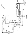
- Figure 8A is a schematic view of a warm recycle system 100 embodiment employing an oxidant heater 10 of the above described novel internal sector arrangement.
- the inventive system 100 incorporates, among other elements, a primary oxidant fan 31, for feeding primary oxidant flow to the oxidant heater 10, located before (or upstream from) the oxidant heater 10. It also comprise a primary oxidant mixer 32 for injecting oxidant into the primary oxidant stream 25, located after (or downstream from) the oxidant heater 10.
- the oxidant which is added to the primary stream 25 by the primary oxidant mixer 32 is in the present example pure or nearly pure oxygen. However, other oxidants such as for example atmospheric air or a mixture of flue gas and oxygen can also be used.
- the static gas pressure differential between the primary and secondary oxidant streams 25, 22 flowing through the primary and secondary combustion oxidant sectors 14, 13 is about +6.227kPa (25 in wg). Therefore, the internal oxidant heater leakage will be from un-oxygenated primary stream 25 into the oxygenated secondary stream 22, as indicated by arrow 15b. Also, the pressure difference between the primary stream 25 and the flue gas stream 20 which respectively flow through the primary sectors 14 and the flue gas side 11 of the oxidant heater 10 is high (i.e., between +11.209kPa to 12.454kPa (+45 to +50 in.
- one method according to the present disclosure includes the steps of providing an oxidant heater 10 with the above described internal sector arrangement; providing a primary oxidant fan 31 upstream from the oxidant heater 10 for feeding the primary oxidant stream 25 flow to the oxidant heater 10; splitting the cold primary combustion oxidant stream 25 before it enters the oxidant heater 10 on its way to the boiler 1; and directing the split primary combustion oxidant stream 25 to flow through the two separate primary combustion oxidant sectors 14;
- a method according to the present disclosure also includes the steps of allowing cold primary oxidant from the primary combustion oxidant stream 25 flowing through the two primary combustion oxidant sectors 14 to leak into both the flue gas side 11 and into the secondary combustion oxidant sector 13; and then introducing oxidant into the primary combustion oxidant stream 25 downstream from the oxidant heater 10.
- the flow of the primary combustion oxidant stream 25 is less than the flow of the secondary combustion oxidant stream 22 and because the amount of oxygen in the primary stream 25 is much less, injecting the cooler oxygen into the primary stream 25 downstream from the oxidant heater 10 has the least impact on the oxidant heater 10 balance (loss of cooling and flow to absorb heat) and, if the oxygen is preheated before mixing with the primary oxygen stream 25 it reduces its impact on achieving the required primary oxygen temperature at the pulverizer for coal drying.
- such a method may include the step of pre-heating the oxidant before it is introduced into the primary combustion oxidant stream 25.
- the primary oxidant fan 31 provides volumetric flow to the primary oxidant stream 25 so that it flows through the oxidant heater 10. Therefore, due to the large amount of internal leakage from the primary combustion oxidant stream 25 to the flue gas stream 20, the flow of primary oxidant flowing out of the oxidant heater 10 toward the boiler 1 is reduced. Thus, it may be appropriate to increase the output of the primary fan 31 to maintain primary flow to the pulverizer 4, compensating for the flow lost to internal leakage.
- one method according to the present disclosure also includes the step of increasing the power to the primary oxidant fan 31 to provide an additional primary flow to the oxidant heater 10.
- the flue gas stream 20 which exits the boiler 1 via the boiler gas exit 2 flows through the flue gas side 11 of the oxidant heater 10. After passing through the oxidant heater 10, a portion 21 of the flue gas stream 20 which exits the oxidant heater 10 splits to form the secondary oxidant stream 22 as well as an intermediate flue gas stream 23.
- a particulate removal unit 34 Downstream from the point at which the portion 21 of the flue gas stream 20 splits is provided a particulate removal unit 34 for removing particulate matter, such as ash, from the secondary combustion oxidant stream 22.
- the system of the present example comprises a secondary oxidant fan 30 for feeding secondary flow to the oxidant heater 10 which is positioned upstream from the oxidant heater 10.
- a secondary oxidant mixer 33 for introducing oxidant into the secondary combustion oxidant stream 22.
- the oxidant which is added to secondary oxidant stream 22 by the secondary oxidant mixer 33 in the present example is pure or nearly pure oxygen.
- other oxidants such as atmospheric air and a mixture of flue gas and oxygen can also be used.
- the secondary oxidant mixer 33 is placed upstream of the secondary oxidant fan 30.
- system of the present example can also comprise a gas quality control system (GQCS) unit 35 located along the intermediate flue gas stream 23.
- GQCS gas quality control system
- the GQCS may comprise particulate, sulfur, and moisture removal devices to treat the passing flow stream. After it passes through the GQCS unit 35, the intermediate flue gas stream 23 splits to form the primary combustion oxidant stream 25 as well as a compression and purification (CPU) stream 24 which leads to a compression and purification unit 36.
- CPU compression and purification
- the primary combustion oxidant stream 25 flows to a coal pulverizer(s) mill 4, where it dries the coal and conveys it to the burners 8, subsequently entering the combustion process.
- the secondary combustion oxidant stream 22 passes through the oxidant heater 10, it flows to a windbox 3 attached to the boiler 1, before entering the burner 8 and exiting into combustion process.
- a method of the present examples may comprise the additional steps of providing a secondary oxidant fan 30 for feeding secondary oxidant stream 22 flow to the oxidant heater 10 and positioning it upstream from the oxidant heater 10; providing a secondary oxidant mixer 33 at a location upstream from the oxidant heater 10 and downstream from the secondary oxidant fan 30 for the purpose of introducing oxidant into the secondary combustion oxidant stream 22.
- the method of the present examples may include the further steps of splitting a portion 21 of the flue gas stream 20 which exits the oxidant heater 10 to form the secondary combustion oxidant stream 22 and an intermediate flue gas stream 23; providing a particulate removal unit 34 along the secondary combustion oxidant stream 22 at a position upstream of the secondary oxidant fan 30; providing an GQCS unit 35 on the intermediary flue gas stream 23; splitting the intermediate flue gas stream 23 after it passes through the GQCS unit 35 to form both the primary combustion oxidant stream 25 and the CPU stream 24 which leads to a compression and purification (CPU) unit 36.
- CPU compression and purification
- the method of the present examples may also comprise the further steps of directing the secondary combustion oxidant stream 22 to the windbox 3, after it passes through the oxidant heater 10 and directing the primary combustion oxidant stream 25 to a coal pulverizer 4 after it passes through the oxidant heater 10 and oxygen mixer 32.
- the system and method of the present disclosure can inhibit loss of oxygen from the process as described above, and it can also provide sufficient cool primary combustion oxidant from the primary combustion oxidant stream 25 to the oxidant heater 10 which along with the oxygenated secondary oxygen stream 22 allows an acceptable oxidant heater 10 exit gas temperature.
- the present disclosure also may reduce total fan power required compared to other conventional systems.
- the primary combustion oxidant stream 25 flowing to the oxidant heater 10 is adjusted by the primary fan 31 to achieve the desired primary outlet flow to the coal pulverizer 4.
- the primary inlet flow to the oxidant heater 10 will be higher than the outlet flow as a result of the internal leakage.
- the flow though the ID fan 27 will be increased by the leakage within the oxidant heater 10.
- the secondary combustion oxidant flow 22 into the oxidant heater 10 is reduced compared to the required outlet flow. This results in a reduced power requirement for the secondary oxidant (or forced draft) fan 30. Since the secondary fan 30 typically operates at about 176.67 degrees Celsius (350 F) or higher (warm recycle embodiments) while the primary fan 31 and ID fan 27 typically operates at about 65.56 degrees Celsius (150 F) or lower the primary stream 25 and intermediate stream 23 is much cooler than the secondary stream 22 hence the power increase for the ID fan 27 and primary fan 31 can be less than the power reduction in the warm secondary fan 30 resulting in a net power savings depending on the magnitude of internal leakages. (See Tables 1 and 2 and FIG. 9 ).
- use of the system and method of the present disclosure can also reduce sulfur and moisture in the boiler 1.
- the flow in the intermediate flue gas stream 23 which splits to form the primary stream 25 and the CPU stream 24 is increased.
- the secondary combustion oxidant stream 22 passes through particulate removal, the secondary fan 30, and is then routed directly back to the oxidant heater 10 and from the oxidant heater 10 to a windbox 3 attached to the boiler 1 with no sulfur or moisture removal.
- the intermediate flue gas stream 23 passes through particulate, sulfur and moisture removal in the GQCS unit 35. As a result, more flow passes through the GQCS unit 35 than would otherwise.
- the oxidant heater 10 is sized so that conversion to full air firing does not change the oxidant heater 10 shell but may require routine changes to baffling and baskets (generally for the first application only), this design of the present disclosure could be converted to full air firing with a relatively simple and inexpensive internal change if necessary.
- system and method of the present disclosure allow the use of a regenerative oxidant heater it reduces a plants capital cost because regenerative oxidant heaters are less costly than separate tubular oxidant heaters and require considerably less space. Additionally, because its use substantially reduces the loss of costly oxygen and in many applications reduces the total fan power requirement, the system and method of the present disclosure enables plant operating cost reductions.
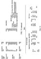
- Tables 1 and 2 below show approximate estimates for oxygen and fan power used when employing the teachings of the present disclosure as compared with separate primary and secondary oxidant heaters. Additionally, FIG. 9 shows oxidant heater balance in a system for warm recycle oxy-fuel combustion which employs the teachings of the present disclosure as compared with what it would be if separate primary and secondary oxidant heaters were used.
- the calculations in Fig. 10 and 11 as well as those in FIG. 7 are based on the assumption that the internal leakage from the primary oxidant stream 25 to the flue gas stream 20 and the secondary oxidant stream 22 is 20.0% and 15.0% respectively.
- the assumed leakage is what would be expected when the pressure of the primary oxidant stream 25 is +11.209kPa (+45 in. wg), when the pressure of the secondary oxidant stream 22 is +6.227kPa (+25 in. wg) and when the pressure of the flue gas stream 20 is 0Pa (0 in. wg).
- the present teachings allow use of a single regenerative oxidant heater. Also, the amount of costly oxygen saved would be about 1.19 metric tons per hour. Additionally, when using the present teachings, there is a reduction in total fan power required of about 50.2 Kilowatts of energy. Furthermore, the total sulfur and moisture contents in the primary and secondary recycle streams to the boiler were noticeably lower. As a result, use of the present teachings significantly reduces plant capital cost as well as plant operating cost as compared with use of a conventional system.
- Fig 8B a schematic illustration of an alternative system configuration embodiment, known as cold recycle is shown.
- flue gas stream 21 is split after the GQCS, thereby subjecting all recycled flow to GQCS treatment prior to being split into primary 23 and secondary 25 streams.
- An alternative location for secondary oxidant mixer 33A is also shown.
Priority Applications (1)
| Application Number | Priority Date | Filing Date | Title |
|---|---|---|---|
| PL11155172T PL2375155T3 (pl) | 2010-04-12 | 2011-02-21 | Układ wewnętrzny i sposób dotyczący podgrzewacza oksydantu do spalania paliwa w atmosferze |
Applications Claiming Priority (1)
| Application Number | Priority Date | Filing Date | Title |
|---|---|---|---|
| US12/712,268 US8807991B2 (en) | 2007-07-10 | 2010-04-12 | Oxy-fuel combustion oxidant heater internal arrangement |
Publications (3)
| Publication Number | Publication Date |
|---|---|
| EP2375155A2 EP2375155A2 (en) | 2011-10-12 |
| EP2375155A3 EP2375155A3 (en) | 2014-11-19 |
| EP2375155B1 true EP2375155B1 (en) | 2017-04-12 |
Family
ID=44260285
Family Applications (1)
| Application Number | Title | Priority Date | Filing Date |
|---|---|---|---|
| EP11155172.7A Not-in-force EP2375155B1 (en) | 2010-04-12 | 2011-02-21 | Oxy-fuel combustion oxidant heater internal arrangement and method |
Country Status (8)
| Country | Link |
|---|---|
| US (1) | US8807991B2 (zh) |
| EP (1) | EP2375155B1 (zh) |
| JP (2) | JP5797912B2 (zh) |
| CN (2) | CN102213440B (zh) |
| AU (1) | AU2011200398B2 (zh) |
| CA (1) | CA2730611C (zh) |
| PL (1) | PL2375155T3 (zh) |
| ZA (1) | ZA201100698B (zh) |
Families Citing this family (9)
| Publication number | Priority date | Publication date | Assignee | Title |
|---|---|---|---|---|
| US8807991B2 (en) * | 2007-07-10 | 2014-08-19 | Babcock & Wilcox Power Generation Group, Inc. | Oxy-fuel combustion oxidant heater internal arrangement |
| EP2743624A1 (en) * | 2012-12-14 | 2014-06-18 | Alstom Technology Ltd | Leakage reduction system in power plant operations |
| TWI572827B (zh) * | 2013-01-04 | 2017-03-01 | Zero Energy Dissipation Device and Method for Volatile Organic Compounds | |
| US9518734B2 (en) | 2013-01-28 | 2016-12-13 | General Electric Technology Gmbh | Fluid distribution and mixing grid for mixing gases |
| US9841242B2 (en) * | 2013-06-21 | 2017-12-12 | General Electric Technology Gmbh | Method of air preheating for combustion power plant and systems comprising the same |
| JP6201600B2 (ja) * | 2013-10-03 | 2017-09-27 | 株式会社Ihi | 酸素燃焼システムの支燃流体予熱装置 |
| JP6273747B2 (ja) * | 2013-10-03 | 2018-02-07 | 株式会社Ihi | 酸素燃焼用の再生回転式予熱器 |
| CN103994462B (zh) * | 2014-06-05 | 2016-07-27 | 山东大学 | 空预脱硝一体反应器及反应方法 |
| CN107101216B (zh) * | 2017-04-20 | 2023-05-09 | 华电电力科学研究院有限公司 | 一种返抽防漏型原净烟气回热式换热系统及其工作方法 |
Family Cites Families (29)
| Publication number | Priority date | Publication date | Assignee | Title |
|---|---|---|---|---|
| DE3140406C2 (de) * | 1981-10-12 | 1985-03-07 | Apparatebau Rothemühle Brandt + Kritzler GmbH, 5963 Wenden | Regenerativ-Wärmeaustauscher zur getrennten Aufwärmung zweier parallel geführter Ströme eines wärmeaufnehmenden Mediums durch ein wärmeabgebendes Medium |
| JPS63176917A (ja) * | 1987-01-19 | 1988-07-21 | Mitsubishi Heavy Ind Ltd | 再生式空気予熱器 |
| JPS63201417A (ja) * | 1987-02-16 | 1988-08-19 | Mitsubishi Heavy Ind Ltd | 空気予熱器 |
| JPS648033U (zh) * | 1987-06-30 | 1989-01-17 | ||
| JPH01305217A (ja) * | 1988-06-02 | 1989-12-08 | Ishikawajima Harima Heavy Ind Co Ltd | ボイラにおけるNOx、CO低減法 |
| US5038849A (en) | 1989-10-24 | 1991-08-13 | Damper Design, Inc. | Sealing of air heaters by deforming sector plates |
| JP3068888B2 (ja) * | 1991-05-28 | 2000-07-24 | 株式会社日立製作所 | 燃焼装置及びその運転方法 |
| JP3422044B2 (ja) * | 1993-06-15 | 2003-06-30 | 石川島播磨重工業株式会社 | 回転再生式空気予熱機 |
| US5915339A (en) * | 1995-06-29 | 1999-06-29 | Abb Air Preheater Inc. | Sector plate and seal arrangement for trisector air preheater |
| US5915340A (en) | 1996-10-02 | 1999-06-29 | Abb Air Preheater Inc. | Variable sector plate quad sector air preheater |
| JP3611272B2 (ja) * | 1997-12-19 | 2005-01-19 | 三菱重工業株式会社 | 回転再生式熱交換器 |
| US6089023A (en) * | 1998-04-29 | 2000-07-18 | Combustion Engineering, Inc. | Steam generator system operation |
| US6202574B1 (en) | 1999-07-09 | 2001-03-20 | Abb Alstom Power Inc. | Combustion method and apparatus for producing a carbon dioxide end product |
| US7082987B2 (en) | 2000-01-19 | 2006-08-01 | Howden Power Limited | Rotary regenerative heat exchanger and rotor therefor |
| US6345442B1 (en) | 2000-05-22 | 2002-02-12 | Abb Alstom Power N.V. | Method of making rotor design with double seals for vertical air preheaters |
| US6505567B1 (en) * | 2001-11-26 | 2003-01-14 | Alstom (Switzerland) Ltd | Oxygen fired circulating fluidized bed steam generator |
| US6647929B1 (en) | 2003-03-07 | 2003-11-18 | Alstom (Switzerland) Ltd | System for increasing efficiency of steam generator system having a regenerative air preheater |
| US6640752B1 (en) | 2003-03-07 | 2003-11-04 | Alstom (Switzerland) Ltd | Boiler and regenerative air preheater arrangement to enhance SO3 capture |
| US6974318B2 (en) | 2004-04-05 | 2005-12-13 | Dürr Environmental, Inc. | Online bakeout of regenerative oxidizers |
| US7475544B2 (en) | 2004-11-02 | 2009-01-13 | Counterman Wayne S | Efficiency improvement for a utility steam generator with a regenerative air preheater |
| US7278378B2 (en) | 2004-11-02 | 2007-10-09 | Counterman Wayne S | Regenerative air preheater leakage recovery system |
| JP4731293B2 (ja) * | 2005-11-28 | 2011-07-20 | 電源開発株式会社 | 酸素燃焼ボイラの燃焼制御方法及び装置 |
| US8327809B2 (en) * | 2007-07-10 | 2012-12-11 | Babcock & Wilcox Power Generation Group, Inc. | Tri-sector regenerative oxidant preheater for oxy-fired pulverized coal combustion |
| US8807991B2 (en) * | 2007-07-10 | 2014-08-19 | Babcock & Wilcox Power Generation Group, Inc. | Oxy-fuel combustion oxidant heater internal arrangement |
| US8196532B2 (en) * | 2008-02-27 | 2012-06-12 | Andrus Jr Herbert E | Air-fired CO2 capture ready circulating fluidized bed heat generation with a reactor subsystem |
| US8453585B2 (en) * | 2008-04-14 | 2013-06-04 | Babcock & Wilcox Power Generation Group, Inc. | Oxy-combustion coal fired boiler and method of transitioning between air and oxygen firing |
| JP4644725B2 (ja) * | 2008-05-07 | 2011-03-02 | 株式会社日立製作所 | 酸素燃焼ボイラシステム,微粉炭燃焼ボイラの改造方法,酸素燃焼ボイラシステムの制御装置及びその制御方法 |
| EP2304366A2 (en) * | 2008-05-30 | 2011-04-06 | Foster Wheeler Energia Oy | Method of and system for generating power by oxyfuel combustion |
| JP5183372B2 (ja) * | 2008-08-29 | 2013-04-17 | 株式会社日立製作所 | 酸素燃焼ボイラシステム及び燃焼方法 |
-
2010
- 2010-04-12 US US12/712,268 patent/US8807991B2/en not_active Expired - Fee Related
-
2011
- 2011-01-27 ZA ZA2011/00698A patent/ZA201100698B/en unknown
- 2011-01-31 AU AU2011200398A patent/AU2011200398B2/en not_active Ceased
- 2011-02-03 CA CA2730611A patent/CA2730611C/en not_active Expired - Fee Related
- 2011-02-21 EP EP11155172.7A patent/EP2375155B1/en not_active Not-in-force
- 2011-02-21 PL PL11155172T patent/PL2375155T3/pl unknown
- 2011-02-25 JP JP2011040187A patent/JP5797912B2/ja not_active Expired - Fee Related
- 2011-02-25 CN CN201110050394.8A patent/CN102213440B/zh not_active Expired - Fee Related
- 2011-02-25 CN CN201510524117.4A patent/CN105157054B/zh not_active Expired - Fee Related
-
2015
- 2015-08-19 JP JP2015162279A patent/JP6099706B2/ja not_active Expired - Fee Related
Non-Patent Citations (1)
| Title |
|---|
| None * |
Also Published As
| Publication number | Publication date |
|---|---|
| ZA201100698B (en) | 2011-10-26 |
| CA2730611A1 (en) | 2011-10-12 |
| CN102213440B (zh) | 2015-12-09 |
| US8807991B2 (en) | 2014-08-19 |
| CN105157054A (zh) | 2015-12-16 |
| JP2011220667A (ja) | 2011-11-04 |
| AU2011200398A1 (en) | 2011-10-27 |
| JP5797912B2 (ja) | 2015-10-21 |
| CA2730611C (en) | 2015-11-24 |
| EP2375155A3 (en) | 2014-11-19 |
| AU2011200398B2 (en) | 2017-04-06 |
| JP2015232438A (ja) | 2015-12-24 |
| CN105157054B (zh) | 2017-11-28 |
| EP2375155A2 (en) | 2011-10-12 |
| CN102213440A (zh) | 2011-10-12 |
| US20110250551A1 (en) | 2011-10-13 |
| JP6099706B2 (ja) | 2017-03-22 |
| PL2375155T3 (pl) | 2017-10-31 |
Similar Documents
| Publication | Publication Date | Title |
|---|---|---|
| EP2375155B1 (en) | Oxy-fuel combustion oxidant heater internal arrangement and method | |
| US7350471B2 (en) | Combustion system with recirculation of flue gas | |
| US5814284A (en) | Plant for the reduction of nitrogen oxide in furnace waste gases | |
| EP2314920B1 (en) | Retrofit method for pulverized coal boiler | |
| CN202595161U (zh) | 高炉炉顶气回收系统 | |
| CN112654828B (zh) | 一种水泥预分解窑系统及制备水泥熟料的方法 | |
| KR20100110826A (ko) | 순산소 연료 연소에 의해 전력을 생성하는 공정을 제어하는 방법 | |
| AU2016201559B2 (en) | Leakage reduction system in power plant operations | |
| US4326041A (en) | Process for the catalytic synthesis of methanol | |
| CN210855855U (zh) | 由在线型分解炉改造的可调节co2富集量水泥窑系统 | |
| KR20120030427A (ko) | 열 회수 모듈 | |
| EP2784388B1 (en) | Method for combustion of a low-grade fuel | |
| US20150353406A1 (en) | Energy recovery from fumes from a melting furnace using a gas turbine and heat exchangers | |
| US9581330B2 (en) | Oxy-fuel combustion oxidant heater internal arrangement | |
| EP3519731B1 (en) | Method for reducing nox emission | |
| Smyth | A proposal for the use of a very high temperature ceramic heat exchanger in gas turbine power production | |
| AU684526B2 (en) | Steam plant for production of electrical energy | |
| TW201337179A (zh) | 旋轉再生熱交換器 | |
| RU2018056C1 (ru) | Котел | |
| JPS6338609B2 (zh) | ||
| Meyer | Effect on the Integrated Energy Economy of a Waste Gas Recovery System for Combustion Agent Preheating in Hot Blast Stove Plants |
Legal Events
| Date | Code | Title | Description |
|---|---|---|---|
| PUAI | Public reference made under article 153(3) epc to a published international application that has entered the european phase |
Free format text: ORIGINAL CODE: 0009012 |
|
| AK | Designated contracting states |
Kind code of ref document: A2 Designated state(s): AL AT BE BG CH CY CZ DE DK EE ES FI FR GB GR HR HU IE IS IT LI LT LU LV MC MK MT NL NO PL PT RO RS SE SI SK SM TR |
|
| AX | Request for extension of the european patent |
Extension state: BA ME |
|
| PUAL | Search report despatched |
Free format text: ORIGINAL CODE: 0009013 |
|
| AK | Designated contracting states |
Kind code of ref document: A3 Designated state(s): AL AT BE BG CH CY CZ DE DK EE ES FI FR GB GR HR HU IE IS IT LI LT LU LV MC MK MT NL NO PL PT RO RS SE SI SK SM TR |
|
| AX | Request for extension of the european patent |
Extension state: BA ME |
|
| RIC1 | Information provided on ipc code assigned before grant |
Ipc: F28D 19/04 20060101ALI20141014BHEP Ipc: F23L 15/02 20060101AFI20141014BHEP |
|
| 17P | Request for examination filed |
Effective date: 20150519 |
|
| RBV | Designated contracting states (corrected) |
Designated state(s): AL AT BE BG CH CY CZ DE DK EE ES FI FR GB GR HR HU IE IS IT LI LT LU LV MC MK MT NL NO PL PT RO RS SE SI SK SM TR |
|
| 17Q | First examination report despatched |
Effective date: 20151016 |
|
| RAP1 | Party data changed (applicant data changed or rights of an application transferred) |
Owner name: THE BABCOCK & WILCOX COMPANY |
|
| GRAP | Despatch of communication of intention to grant a patent |
Free format text: ORIGINAL CODE: EPIDOSNIGR1 |
|
| INTG | Intention to grant announced |
Effective date: 20160908 |
|
| STAA | Information on the status of an ep patent application or granted ep patent |
Free format text: STATUS: GRANT OF PATENT IS INTENDED |
|
| GRAS | Grant fee paid |
Free format text: ORIGINAL CODE: EPIDOSNIGR3 |
|
| GRAA | (expected) grant |
Free format text: ORIGINAL CODE: 0009210 |
|
| STAA | Information on the status of an ep patent application or granted ep patent |
Free format text: STATUS: THE PATENT HAS BEEN GRANTED |
|
| AK | Designated contracting states |
Kind code of ref document: B1 Designated state(s): AL AT BE BG CH CY CZ DE DK EE ES FI FR GB GR HR HU IE IS IT LI LT LU LV MC MK MT NL NO PL PT RO RS SE SI SK SM TR |
|
| REG | Reference to a national code |
Ref country code: GB Ref legal event code: FG4D |
|
| REG | Reference to a national code |
Ref country code: CH Ref legal event code: EP |
|
| REG | Reference to a national code |
Ref country code: IE Ref legal event code: FG4D |
|
| REG | Reference to a national code |
Ref country code: AT Ref legal event code: REF Ref document number: 884291 Country of ref document: AT Kind code of ref document: T Effective date: 20170515 |
|
| REG | Reference to a national code |
Ref country code: DE Ref legal event code: R096 Ref document number: 602011036817 Country of ref document: DE |
|
| REG | Reference to a national code |
Ref country code: RO Ref legal event code: EPE |
|
| REG | Reference to a national code |
Ref country code: NL Ref legal event code: MP Effective date: 20170412 |
|
| REG | Reference to a national code |
Ref country code: LT Ref legal event code: MG4D |
|
| PG25 | Lapsed in a contracting state [announced via postgrant information from national office to epo] |
Ref country code: NL Free format text: LAPSE BECAUSE OF FAILURE TO SUBMIT A TRANSLATION OF THE DESCRIPTION OR TO PAY THE FEE WITHIN THE PRESCRIBED TIME-LIMIT Effective date: 20170412 |
|
| PG25 | Lapsed in a contracting state [announced via postgrant information from national office to epo] |
Ref country code: HR Free format text: LAPSE BECAUSE OF FAILURE TO SUBMIT A TRANSLATION OF THE DESCRIPTION OR TO PAY THE FEE WITHIN THE PRESCRIBED TIME-LIMIT Effective date: 20170412 Ref country code: LT Free format text: LAPSE BECAUSE OF FAILURE TO SUBMIT A TRANSLATION OF THE DESCRIPTION OR TO PAY THE FEE WITHIN THE PRESCRIBED TIME-LIMIT Effective date: 20170412 Ref country code: FI Free format text: LAPSE BECAUSE OF FAILURE TO SUBMIT A TRANSLATION OF THE DESCRIPTION OR TO PAY THE FEE WITHIN THE PRESCRIBED TIME-LIMIT Effective date: 20170412 Ref country code: NO Free format text: LAPSE BECAUSE OF FAILURE TO SUBMIT A TRANSLATION OF THE DESCRIPTION OR TO PAY THE FEE WITHIN THE PRESCRIBED TIME-LIMIT Effective date: 20170712 Ref country code: GR Free format text: LAPSE BECAUSE OF FAILURE TO SUBMIT A TRANSLATION OF THE DESCRIPTION OR TO PAY THE FEE WITHIN THE PRESCRIBED TIME-LIMIT Effective date: 20170713 Ref country code: ES Free format text: LAPSE BECAUSE OF FAILURE TO SUBMIT A TRANSLATION OF THE DESCRIPTION OR TO PAY THE FEE WITHIN THE PRESCRIBED TIME-LIMIT Effective date: 20170412 |
|
| PG25 | Lapsed in a contracting state [announced via postgrant information from national office to epo] |
Ref country code: BG Free format text: LAPSE BECAUSE OF FAILURE TO SUBMIT A TRANSLATION OF THE DESCRIPTION OR TO PAY THE FEE WITHIN THE PRESCRIBED TIME-LIMIT Effective date: 20170712 Ref country code: RS Free format text: LAPSE BECAUSE OF FAILURE TO SUBMIT A TRANSLATION OF THE DESCRIPTION OR TO PAY THE FEE WITHIN THE PRESCRIBED TIME-LIMIT Effective date: 20170412 Ref country code: LV Free format text: LAPSE BECAUSE OF FAILURE TO SUBMIT A TRANSLATION OF THE DESCRIPTION OR TO PAY THE FEE WITHIN THE PRESCRIBED TIME-LIMIT Effective date: 20170412 Ref country code: IS Free format text: LAPSE BECAUSE OF FAILURE TO SUBMIT A TRANSLATION OF THE DESCRIPTION OR TO PAY THE FEE WITHIN THE PRESCRIBED TIME-LIMIT Effective date: 20170812 Ref country code: SE Free format text: LAPSE BECAUSE OF FAILURE TO SUBMIT A TRANSLATION OF THE DESCRIPTION OR TO PAY THE FEE WITHIN THE PRESCRIBED TIME-LIMIT Effective date: 20170412 |
|
| REG | Reference to a national code |
Ref country code: SK Ref legal event code: T3 Ref document number: E 24704 Country of ref document: SK |
|
| REG | Reference to a national code |
Ref country code: DE Ref legal event code: R097 Ref document number: 602011036817 Country of ref document: DE |
|
| REG | Reference to a national code |
Ref country code: HU Ref legal event code: AG4A Ref document number: E033807 Country of ref document: HU |
|
| PG25 | Lapsed in a contracting state [announced via postgrant information from national office to epo] |
Ref country code: EE Free format text: LAPSE BECAUSE OF FAILURE TO SUBMIT A TRANSLATION OF THE DESCRIPTION OR TO PAY THE FEE WITHIN THE PRESCRIBED TIME-LIMIT Effective date: 20170412 Ref country code: DK Free format text: LAPSE BECAUSE OF FAILURE TO SUBMIT A TRANSLATION OF THE DESCRIPTION OR TO PAY THE FEE WITHIN THE PRESCRIBED TIME-LIMIT Effective date: 20170412 |
|
| PLBE | No opposition filed within time limit |
Free format text: ORIGINAL CODE: 0009261 |
|
| STAA | Information on the status of an ep patent application or granted ep patent |
Free format text: STATUS: NO OPPOSITION FILED WITHIN TIME LIMIT |
|
| PG25 | Lapsed in a contracting state [announced via postgrant information from national office to epo] |
Ref country code: SM Free format text: LAPSE BECAUSE OF FAILURE TO SUBMIT A TRANSLATION OF THE DESCRIPTION OR TO PAY THE FEE WITHIN THE PRESCRIBED TIME-LIMIT Effective date: 20170412 |
|
| 26N | No opposition filed |
Effective date: 20180115 |
|
| PG25 | Lapsed in a contracting state [announced via postgrant information from national office to epo] |
Ref country code: SI Free format text: LAPSE BECAUSE OF FAILURE TO SUBMIT A TRANSLATION OF THE DESCRIPTION OR TO PAY THE FEE WITHIN THE PRESCRIBED TIME-LIMIT Effective date: 20170412 |
|
| REG | Reference to a national code |
Ref country code: CH Ref legal event code: PL |
|
| PG25 | Lapsed in a contracting state [announced via postgrant information from national office to epo] |
Ref country code: MC Free format text: LAPSE BECAUSE OF FAILURE TO SUBMIT A TRANSLATION OF THE DESCRIPTION OR TO PAY THE FEE WITHIN THE PRESCRIBED TIME-LIMIT Effective date: 20170412 |
|
| GBPC | Gb: european patent ceased through non-payment of renewal fee |
Effective date: 20180221 |
|
| REG | Reference to a national code |
Ref country code: BE Ref legal event code: MM Effective date: 20180228 |
|
| PG25 | Lapsed in a contracting state [announced via postgrant information from national office to epo] |
Ref country code: LI Free format text: LAPSE BECAUSE OF NON-PAYMENT OF DUE FEES Effective date: 20180228 Ref country code: CH Free format text: LAPSE BECAUSE OF NON-PAYMENT OF DUE FEES Effective date: 20180228 Ref country code: LU Free format text: LAPSE BECAUSE OF NON-PAYMENT OF DUE FEES Effective date: 20180221 |
|
| REG | Reference to a national code |
Ref country code: FR Ref legal event code: ST Effective date: 20181031 |
|
| REG | Reference to a national code |
Ref country code: IE Ref legal event code: MM4A |
|
| PG25 | Lapsed in a contracting state [announced via postgrant information from national office to epo] |
Ref country code: IE Free format text: LAPSE BECAUSE OF NON-PAYMENT OF DUE FEES Effective date: 20180221 |
|
| PG25 | Lapsed in a contracting state [announced via postgrant information from national office to epo] |
Ref country code: GB Free format text: LAPSE BECAUSE OF NON-PAYMENT OF DUE FEES Effective date: 20180221 Ref country code: FR Free format text: LAPSE BECAUSE OF NON-PAYMENT OF DUE FEES Effective date: 20180228 Ref country code: BE Free format text: LAPSE BECAUSE OF NON-PAYMENT OF DUE FEES Effective date: 20180228 |
|
| REG | Reference to a national code |
Ref country code: AT Ref legal event code: UEP Ref document number: 884291 Country of ref document: AT Kind code of ref document: T Effective date: 20170412 |
|
| PG25 | Lapsed in a contracting state [announced via postgrant information from national office to epo] |
Ref country code: MT Free format text: LAPSE BECAUSE OF NON-PAYMENT OF DUE FEES Effective date: 20180221 |
|
| PG25 | Lapsed in a contracting state [announced via postgrant information from national office to epo] |
Ref country code: TR Free format text: LAPSE BECAUSE OF FAILURE TO SUBMIT A TRANSLATION OF THE DESCRIPTION OR TO PAY THE FEE WITHIN THE PRESCRIBED TIME-LIMIT Effective date: 20170412 |
|
| PGFP | Annual fee paid to national office [announced via postgrant information from national office to epo] |
Ref country code: HU Payment date: 20200214 Year of fee payment: 10 Ref country code: IT Payment date: 20200220 Year of fee payment: 10 Ref country code: PL Payment date: 20200203 Year of fee payment: 10 Ref country code: RO Payment date: 20200207 Year of fee payment: 10 Ref country code: AT Payment date: 20200203 Year of fee payment: 10 Ref country code: DE Payment date: 20200227 Year of fee payment: 10 |
|
| PG25 | Lapsed in a contracting state [announced via postgrant information from national office to epo] |
Ref country code: PT Free format text: LAPSE BECAUSE OF FAILURE TO SUBMIT A TRANSLATION OF THE DESCRIPTION OR TO PAY THE FEE WITHIN THE PRESCRIBED TIME-LIMIT Effective date: 20170412 |
|
| PGFP | Annual fee paid to national office [announced via postgrant information from national office to epo] |
Ref country code: SK Payment date: 20200131 Year of fee payment: 10 Ref country code: CZ Payment date: 20200207 Year of fee payment: 10 |
|
| PG25 | Lapsed in a contracting state [announced via postgrant information from national office to epo] |
Ref country code: MK Free format text: LAPSE BECAUSE OF NON-PAYMENT OF DUE FEES Effective date: 20170412 Ref country code: CY Free format text: LAPSE BECAUSE OF FAILURE TO SUBMIT A TRANSLATION OF THE DESCRIPTION OR TO PAY THE FEE WITHIN THE PRESCRIBED TIME-LIMIT Effective date: 20170412 |
|
| PG25 | Lapsed in a contracting state [announced via postgrant information from national office to epo] |
Ref country code: AL Free format text: LAPSE BECAUSE OF FAILURE TO SUBMIT A TRANSLATION OF THE DESCRIPTION OR TO PAY THE FEE WITHIN THE PRESCRIBED TIME-LIMIT Effective date: 20170412 |
|
| REG | Reference to a national code |
Ref country code: DE Ref legal event code: R082 Ref document number: 602011036817 Country of ref document: DE Representative=s name: D YOUNG & CO LLP, DE |
|
| REG | Reference to a national code |
Ref country code: DE Ref legal event code: R119 Ref document number: 602011036817 Country of ref document: DE |
|
| REG | Reference to a national code |
Ref country code: AT Ref legal event code: MM01 Ref document number: 884291 Country of ref document: AT Kind code of ref document: T Effective date: 20210221 |
|
| REG | Reference to a national code |
Ref country code: SK Ref legal event code: MM4A Ref document number: E 24704 Country of ref document: SK Effective date: 20210221 |
|
| PG25 | Lapsed in a contracting state [announced via postgrant information from national office to epo] |
Ref country code: CZ Free format text: LAPSE BECAUSE OF NON-PAYMENT OF DUE FEES Effective date: 20210221 Ref country code: HU Free format text: LAPSE BECAUSE OF NON-PAYMENT OF DUE FEES Effective date: 20210222 Ref country code: AT Free format text: LAPSE BECAUSE OF NON-PAYMENT OF DUE FEES Effective date: 20210221 |
|
| PG25 | Lapsed in a contracting state [announced via postgrant information from national office to epo] |
Ref country code: RO Free format text: LAPSE BECAUSE OF NON-PAYMENT OF DUE FEES Effective date: 20210221 Ref country code: SK Free format text: LAPSE BECAUSE OF NON-PAYMENT OF DUE FEES Effective date: 20210221 |
|
| PG25 | Lapsed in a contracting state [announced via postgrant information from national office to epo] |
Ref country code: DE Free format text: LAPSE BECAUSE OF NON-PAYMENT OF DUE FEES Effective date: 20210901 |
|
| PG25 | Lapsed in a contracting state [announced via postgrant information from national office to epo] |
Ref country code: IT Free format text: LAPSE BECAUSE OF NON-PAYMENT OF DUE FEES Effective date: 20210221 |
|
| PG25 | Lapsed in a contracting state [announced via postgrant information from national office to epo] |
Ref country code: PL Free format text: LAPSE BECAUSE OF NON-PAYMENT OF DUE FEES Effective date: 20210221 |