EP2374494A2 - Lunette à air, embout nasal, élément en Y et procédé associé - Google Patents
Lunette à air, embout nasal, élément en Y et procédé associé Download PDFInfo
- Publication number
- EP2374494A2 EP2374494A2 EP10186319A EP10186319A EP2374494A2 EP 2374494 A2 EP2374494 A2 EP 2374494A2 EP 10186319 A EP10186319 A EP 10186319A EP 10186319 A EP10186319 A EP 10186319A EP 2374494 A2 EP2374494 A2 EP 2374494A2
- Authority
- EP
- European Patent Office
- Prior art keywords
- piece
- air
- fork tube
- goggles
- heating wire
- Prior art date
- Legal status (The legal status is an assumption and is not a legal conclusion. Google has not performed a legal analysis and makes no representation as to the accuracy of the status listed.)
- Granted
Links
- 238000000034 method Methods 0.000 title claims abstract description 12
- 238000010438 heat treatment Methods 0.000 claims abstract description 72
- 230000005494 condensation Effects 0.000 claims abstract description 11
- 238000009833 condensation Methods 0.000 claims abstract description 9
- 230000007704 transition Effects 0.000 claims description 29
- 238000009413 insulation Methods 0.000 claims description 22
- 229910052751 metal Inorganic materials 0.000 claims description 10
- 239000002184 metal Substances 0.000 claims description 10
- 230000000087 stabilizing effect Effects 0.000 claims description 5
- 206010041235 Snoring Diseases 0.000 claims description 4
- 239000011521 glass Substances 0.000 abstract description 6
- 239000007789 gas Substances 0.000 description 13
- QVGXLLKOCUKJST-UHFFFAOYSA-N atomic oxygen Chemical compound [O] QVGXLLKOCUKJST-UHFFFAOYSA-N 0.000 description 9
- 229910052760 oxygen Inorganic materials 0.000 description 9
- 239000001301 oxygen Substances 0.000 description 9
- 101100116570 Caenorhabditis elegans cup-2 gene Proteins 0.000 description 6
- 101100116572 Drosophila melanogaster Der-1 gene Proteins 0.000 description 6
- 230000006641 stabilisation Effects 0.000 description 6
- 238000011105 stabilization Methods 0.000 description 6
- 208000008784 apnea Diseases 0.000 description 4
- 230000001419 dependent effect Effects 0.000 description 4
- 238000005259 measurement Methods 0.000 description 4
- 239000000463 material Substances 0.000 description 3
- 230000009467 reduction Effects 0.000 description 3
- 210000002345 respiratory system Anatomy 0.000 description 3
- 208000023504 respiratory system disease Diseases 0.000 description 3
- CURLTUGMZLYLDI-UHFFFAOYSA-N Carbon dioxide Chemical compound O=C=O CURLTUGMZLYLDI-UHFFFAOYSA-N 0.000 description 2
- 230000008901 benefit Effects 0.000 description 2
- 230000015572 biosynthetic process Effects 0.000 description 2
- 238000011513 continuous positive airway pressure therapy Methods 0.000 description 2
- 238000001816 cooling Methods 0.000 description 2
- 238000006073 displacement reaction Methods 0.000 description 2
- 238000007373 indentation Methods 0.000 description 2
- 238000004519 manufacturing process Methods 0.000 description 2
- 239000000203 mixture Substances 0.000 description 2
- 230000000414 obstructive effect Effects 0.000 description 2
- 238000005192 partition Methods 0.000 description 2
- 239000004033 plastic Substances 0.000 description 2
- 229920003023 plastic Polymers 0.000 description 2
- 230000000241 respiratory effect Effects 0.000 description 2
- 241001136792 Alle Species 0.000 description 1
- UGFAIRIUMAVXCW-UHFFFAOYSA-N Carbon monoxide Chemical compound [O+]#[C-] UGFAIRIUMAVXCW-UHFFFAOYSA-N 0.000 description 1
- 208000024172 Cardiovascular disease Diseases 0.000 description 1
- 241000511343 Chondrostoma nasus Species 0.000 description 1
- MYMOFIZGZYHOMD-UHFFFAOYSA-N Dioxygen Chemical compound O=O MYMOFIZGZYHOMD-UHFFFAOYSA-N 0.000 description 1
- 206010021143 Hypoxia Diseases 0.000 description 1
- 206010038669 Respiratory arrest Diseases 0.000 description 1
- 208000036071 Rhinorrhea Diseases 0.000 description 1
- 206010039101 Rhinorrhoea Diseases 0.000 description 1
- HCHKCACWOHOZIP-UHFFFAOYSA-N Zinc Chemical compound [Zn] HCHKCACWOHOZIP-UHFFFAOYSA-N 0.000 description 1
- 230000001154 acute effect Effects 0.000 description 1
- 230000006399 behavior Effects 0.000 description 1
- 238000005452 bending Methods 0.000 description 1
- 238000009529 body temperature measurement Methods 0.000 description 1
- 229910052799 carbon Inorganic materials 0.000 description 1
- 229910002092 carbon dioxide Inorganic materials 0.000 description 1
- 239000001569 carbon dioxide Substances 0.000 description 1
- 229910002091 carbon monoxide Inorganic materials 0.000 description 1
- 230000008859 change Effects 0.000 description 1
- 238000006243 chemical reaction Methods 0.000 description 1
- 230000001684 chronic effect Effects 0.000 description 1
- 239000004020 conductor Substances 0.000 description 1
- 238000010276 construction Methods 0.000 description 1
- 230000001276 controlling effect Effects 0.000 description 1
- 238000013461 design Methods 0.000 description 1
- 238000011161 development Methods 0.000 description 1
- 238000010586 diagram Methods 0.000 description 1
- 238000010292 electrical insulation Methods 0.000 description 1
- 239000002657 fibrous material Substances 0.000 description 1
- 239000003063 flame retardant Substances 0.000 description 1
- 230000017525 heat dissipation Effects 0.000 description 1
- 208000018875 hypoxemia Diseases 0.000 description 1
- 239000012774 insulation material Substances 0.000 description 1
- 230000010354 integration Effects 0.000 description 1
- 238000002955 isolation Methods 0.000 description 1
- 239000000155 melt Substances 0.000 description 1
- 208000010125 myocardial infarction Diseases 0.000 description 1
- 238000013021 overheating Methods 0.000 description 1
- 210000003254 palate Anatomy 0.000 description 1
- 231100000572 poisoning Toxicity 0.000 description 1
- 230000000607 poisoning effect Effects 0.000 description 1
- 229920001296 polysiloxane Polymers 0.000 description 1
- 230000001105 regulatory effect Effects 0.000 description 1
- 230000002040 relaxant effect Effects 0.000 description 1
- 230000035939 shock Effects 0.000 description 1
- 239000000779 smoke Substances 0.000 description 1
- 238000002560 therapeutic procedure Methods 0.000 description 1
- 210000001519 tissue Anatomy 0.000 description 1
- XLYOFNOQVPJJNP-UHFFFAOYSA-N water Substances O XLYOFNOQVPJJNP-UHFFFAOYSA-N 0.000 description 1
- 229910052725 zinc Inorganic materials 0.000 description 1
- 239000011701 zinc Substances 0.000 description 1
Images


Classifications
-
- A—HUMAN NECESSITIES
- A61—MEDICAL OR VETERINARY SCIENCE; HYGIENE
- A61M—DEVICES FOR INTRODUCING MEDIA INTO, OR ONTO, THE BODY; DEVICES FOR TRANSDUCING BODY MEDIA OR FOR TAKING MEDIA FROM THE BODY; DEVICES FOR PRODUCING OR ENDING SLEEP OR STUPOR
- A61M16/00—Devices for influencing the respiratory system of patients by gas treatment, e.g. mouth-to-mouth respiration; Tracheal tubes
- A61M16/06—Respiratory or anaesthetic masks
- A61M16/0666—Nasal cannulas or tubing
-
- A—HUMAN NECESSITIES
- A61—MEDICAL OR VETERINARY SCIENCE; HYGIENE
- A61M—DEVICES FOR INTRODUCING MEDIA INTO, OR ONTO, THE BODY; DEVICES FOR TRANSDUCING BODY MEDIA OR FOR TAKING MEDIA FROM THE BODY; DEVICES FOR PRODUCING OR ENDING SLEEP OR STUPOR
- A61M16/00—Devices for influencing the respiratory system of patients by gas treatment, e.g. mouth-to-mouth respiration; Tracheal tubes
- A61M16/08—Bellows; Connecting tubes ; Water traps; Patient circuits
- A61M16/0816—Joints or connectors
- A61M16/0833—T- or Y-type connectors, e.g. Y-piece
-
- A—HUMAN NECESSITIES
- A61—MEDICAL OR VETERINARY SCIENCE; HYGIENE
- A61M—DEVICES FOR INTRODUCING MEDIA INTO, OR ONTO, THE BODY; DEVICES FOR TRANSDUCING BODY MEDIA OR FOR TAKING MEDIA FROM THE BODY; DEVICES FOR PRODUCING OR ENDING SLEEP OR STUPOR
- A61M16/00—Devices for influencing the respiratory system of patients by gas treatment, e.g. mouth-to-mouth respiration; Tracheal tubes
- A61M16/10—Preparation of respiratory gases or vapours
- A61M16/1075—Preparation of respiratory gases or vapours by influencing the temperature
- A61M16/1095—Preparation of respiratory gases or vapours by influencing the temperature in the connecting tubes
-
- A—HUMAN NECESSITIES
- A61—MEDICAL OR VETERINARY SCIENCE; HYGIENE
- A61M—DEVICES FOR INTRODUCING MEDIA INTO, OR ONTO, THE BODY; DEVICES FOR TRANSDUCING BODY MEDIA OR FOR TAKING MEDIA FROM THE BODY; DEVICES FOR PRODUCING OR ENDING SLEEP OR STUPOR
- A61M16/00—Devices for influencing the respiratory system of patients by gas treatment, e.g. mouth-to-mouth respiration; Tracheal tubes
- A61M16/08—Bellows; Connecting tubes ; Water traps; Patient circuits
- A61M16/0808—Condensation traps
-
- A—HUMAN NECESSITIES
- A61—MEDICAL OR VETERINARY SCIENCE; HYGIENE
- A61M—DEVICES FOR INTRODUCING MEDIA INTO, OR ONTO, THE BODY; DEVICES FOR TRANSDUCING BODY MEDIA OR FOR TAKING MEDIA FROM THE BODY; DEVICES FOR PRODUCING OR ENDING SLEEP OR STUPOR
- A61M2205/00—General characteristics of the apparatus
- A61M2205/33—Controlling, regulating or measuring
- A61M2205/3368—Temperature
- A61M2205/3372—Temperature compensation
-
- A—HUMAN NECESSITIES
- A61—MEDICAL OR VETERINARY SCIENCE; HYGIENE
- A61M—DEVICES FOR INTRODUCING MEDIA INTO, OR ONTO, THE BODY; DEVICES FOR TRANSDUCING BODY MEDIA OR FOR TAKING MEDIA FROM THE BODY; DEVICES FOR PRODUCING OR ENDING SLEEP OR STUPOR
- A61M2205/00—General characteristics of the apparatus
- A61M2205/36—General characteristics of the apparatus related to heating or cooling
- A61M2205/3653—General characteristics of the apparatus related to heating or cooling by Joule effect, i.e. electric resistance
-
- A—HUMAN NECESSITIES
- A61—MEDICAL OR VETERINARY SCIENCE; HYGIENE
- A61M—DEVICES FOR INTRODUCING MEDIA INTO, OR ONTO, THE BODY; DEVICES FOR TRANSDUCING BODY MEDIA OR FOR TAKING MEDIA FROM THE BODY; DEVICES FOR PRODUCING OR ENDING SLEEP OR STUPOR
- A61M2205/00—General characteristics of the apparatus
- A61M2205/42—Reducing noise
Definitions
- the invention relates to the technical field of goggles according to the preamble of claim 1, of nose pieces therefor according to the preambles of claims 12 to 15, of Y-pieces according to the preamble of claim 16 and of methods according to the preamble of claim 19.
- the invention relates to design changes that facilitate the use of air goggles in the pneumatic upper airway splinting.
- CPAP continuous positive airway pressure
- CPAP therapy In CPAP therapy, a patient is given a constant positive pressure via a nasal mask to appear in the upper airway. If the overpressure is properly selected, it will ensure that the upper airways remain fully open throughout the night, preventing obstructive respiratory disorders. Among other things, to improve comfort BiLevel devices were developed, which lower the pressure during the breather. As generic term for devices for the pneumatic splinting of the upper respiratory tract the term PAP devices is used here.
- Snoring and apneas may have the same cause, namely flabby palate and tongue tissue.
- Oxygen glasses for oxygen treatment are also known from the prior art. With the oxygen goggles, the patient is air with an increased oxygen partial pressure (> 210 mbar) or pure oxygen in the Nose applied.
- oxygen treatment occurs in acute or chronic hypoxemia due to respiratory or cardiovascular disorder (myocardial infarction, shock) or certain poisoning, for example, carbon monoxide, carbon dioxide, fluorescent gas or smoke.
- Oxygen goggles are referred to in this context as air goggles.
- Vapotherm 2000i is a humidification system that delivers air flows in the range of 8 to 40 l / min via nasal cannula to patients.
- the extracted air is humidified and heated.
- Air can be enriched with oxygen.
- the heating of a forked tube by means of a heating wire can prevent the compensation of moisture in the forked tube.
- a laying of the heating wire inside the fork tube is easy to manufacture. Due to the heat dissipation to the environment of the fork tube, the temperature in the fork tube drops approximately linearly with the distance from the compressor. This temperature drop can be compensated by a constant heat output per unit length, as they just created a heating wire. Due to the construction of the hose, the required heat output for the entire air-rollover can be kept below 15 watts. Otherwise, due to legal requirements, the use of fire-retardant plastics would be required, which are generally not biocompatible and whose use is therefore problematic in medical devices.
- a measurement of the temperature of the applied air makes it possible to control the heat output of a heating wire or a heater in a compressor housing in such a way that that the temperature is perceived by the user as pleasant. Without compensation for the temperature drop in the forked tube, the application openings in the tines would be the coldest places. Consequently, air humidity will most likely condense here. For this reason, a heat output control, due to a temperature measurement near the application ports, is best suited to prevent condensation in the entire goggle.
- a triangular cross-section of the elevations advantageously ensures that the contact area between the insulation of the heating wire and the inside of the fork tube remains small both in normal operation and when bent.
- the overall star-shaped cross-section of the insulation advantageously increases the surface of the insulation and thus provides for a reduction of the thermal resistance between the insulation and the passing air.
- Also extending in the longitudinal direction of the fork tube projections provide in an advantageous manner that even then sufficient air flow is ensured inter alia for cooling the heating wire, if the fork tube kinks.
- Stabilization threads serve to reduce a longitudinal expansion of the tubes.
- Inner radius stages at different connection points can just compensate for the hose thickness, so that after attachment of a hose, the transition between the hose and the corresponding component is smooth. A smooth transition creates less vortex and therefore less noise.
- transition areas between a tine and the central connector and a tine and the connector on the side of the tine are rounded to prevent vortex formation and thus a noise emission in an advantageous manner.
- an optimal flow resistance of the connector can be adjusted.
- Fig. 1 shows a goggle according to the invention 1 with a first embodiment of a nose piece 2.
- Nose piece 2 is supplied via a fork hose 3, a Y-piece 4, a supply hose 5, and a plug 6 with compressed air.
- Nose piece 2 has two prongs 12 for the application of air in the two nostrils of a user.
- Inner radius stages 16 compensate for the difference between the inner and outer radius of the fork tubes and thus prevent sudden changes in the cross section of the airways.
- Plug 6 has a pneumatic connector part 10, an electrical connector part 9 and a bracket 11. From the electrical connector part 9 performs a heating wire 8 through supply hose 5, Y-piece 4, the right piece of fork hose 3, the right part of the nose piece 2 to a temperature sensor 7 and from there through the left part of the nose piece 2, the left piece of forked hose 3, Y-piece 4 and supply hose 5 to the electrical connector part 9 back.
- the clip 11 snaps into place on a connector provided for 6 socket and secures connector 6 against unintentional withdrawal.
- a possible cross section of fork tube 3 and supply hose 5 is in connection with Fig. 6 explained.
- Feed hose 5 has a larger cross-section than fork hose 3, because feed hose 5 typically has to transport twice the air flow, the distance to be bridged is greater and the loss of comfort with a large hose thickness is lower.
- the word forked hose was chosen only because supply hose 5 "aufgabelt" at Y-piece 4.
- heating wire 8 runs in the area of nose piece 2 in an additional lumen 17th
- the component 7 can be a temperature switch 19, which can be understood as a temperature sensor with a poor resolution of one bit.
- the temperature switch can be realized for example by a bimetallic contact, for example, with a triggering temperature in the range of 30 ° C to 50 ° C, in particular of 40 ° C. If the temperature of the temperature switch exceeds the trip temperature, the heating circuit is interrupted.
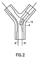
- a temperature sensor or switch 19 may be accommodated in the Y-piece 4, as shown in FIG Fig. 2 is shown.
- An additional temperature switch for example a bimetallic contact with a release temperature of (50 ⁇ 10) ° C, can represent a further safeguard against overheating, for example, when accidentally kinking the fork hose 3 and / or the supply hose 5. Above the trip temperature, the heating circuit is interrupted.
- the in Fig. 2 illustrated temperature switch 19 is a schematic bimetallic contact.
- a temperature sensor or switch 19 alone can effectively prevent condensation since the Y-piece does not end the supply hose 5 heated by the patient's body. Insofar is located in the supply hose 5 of the coldest and thus most susceptible to condensation point between the compressor and nose piece 2. Is the Temperature of the coldest point held above the dew point, no condensation takes place. A displacement of the temperature sensor or switch in the Y-piece 4 can increase the wearing comfort of the air rims 1, because the nose piece 2 can be made lighter and smaller.
- approximately the air temperature in the prongs 12 can be calculated from the temperature in the Y-piece, the heating power and the set flow, a displacement of the temperature sensor from the nosepiece 2 into the Y-piece Piece 4 to no significant loss of comfort.
- Fig. 3 shows a second embodiment of a pair of air goggles, wherein the supply hose 5 and Y-piece 4 are replaced by a double lumen tube 13.
- the double lumen tube consists of two forked tube pieces, which are mechanically connected to each other.
- the Y-piece 4 is omitted or is integrated according to another view in the connector 6.
- a clamp 14 may be provided which prevents further splicing of the double lumen tube.
- the division of an air flow on two forked tube pieces can be done in the plug 6 and is thus further away from the tines 12, so that the noise emission is lower.
- Fig. 4 shows a way to read a temperature sensor over only two heating wires.
- the two heating wires 8 are in the in FIG. 4 shown equivalent circuit diagram represented by the two resistors R H.
- R T represents a two-terminal with temperature-dependent terminal behavior.
- the resistor R T is only a temperature-dependent resistor such as a Pt100 or Pt1000.
- R T is big compared to R H.
- the heating wires typically have a resistance of 15 ⁇ with large tolerances. If a positive heating voltage U H is applied to the three resistors connected in series, then the temperature sensor is short-circuited by the diode D connected in parallel, so that essentially only the heating wires are heated. If a negative or a small measuring voltage UM is applied to the three series-connected resistors, the greater part of the measuring voltage drops at the temperature sensor R T. From this, the temperature of the Temperature sensor can be determined. The remaining voltage drops at the heating resistors can be eliminated.
- diode D serves to bridge and thus protect the integrated circuit for the heating current.
- a Schottky diode can be used for the diode D because of its low forward voltage.
- the direction of the measuring current is directed counter to the heating current. Its amount depends on the temperature and the integrated circuit used and is a few 100 ⁇ A. The particular advantage of this solution is that the wire resistance practically does not affect the measurement result.
- the conversion of the temperature signal by modulating on the heating current is possible. This can be done both analog and digital and realized in customer-specific circuits. Such circuits are known, for example, from telephones or baby monitors for modulating audio frequency signals to the operating voltage.
- the polarity or magnitude of the applied voltage can be switched much faster than the thermal inertia of the system, so that switching between the heater voltage U H and the measurement voltage UM has virtually no temperature change.
- Fig. 4 shows a section through the embodiment of a heating wire 8.
- a metal wire 21 is embedded in an insulation 22.
- the insulation has a star-shaped cross section with five triangular rays and is therefore invariant with respect to rotations by 72 °.
- the metal wire 21 may have a star-shaped cross-section. Each ray forms an elevation running along the wire.
- the bumps can also run helically around the lateral surface, wherein the length of a circulation is typically a multiple of the extent of the insulation.
- the purpose of the star-shaped insulation is to increase the surface area of the wire and thus reduce the thermal resistance to the surrounding air. In addition, even when kinked hose of the heating wire should be circulated as possible on all sides of air, not to overheat and melt into the surrounding tube.
- the triangular rays of the cross section spread the kink of a hose whereby the contact area between the hose and the insulation is small and thus the thermal resistance remains high.
- the metal wire 21 may have a diameter of about 0.3 mm and a circle that just encloses the tips of the cross section have a diameter of 1 mm.
- Fig. 6 shows a section through a hose, which may be a fork hose 3 or a supply hose 5. Both types of tubes typically differ mainly by their diameter.
- the inner circumferential surface of the hose has projections 32, which serve to spread the jacket of the hose at kinks in order not to completely cut off the air flow despite kink.
- stabilizing threads 31 and 33 are on or introduced to reduce a longitudinal expansion of the hose.
- the stabilizing threads 31 and 33 can be introduced into the tubing during the manufacturing process, in particular into protrusions 32.
- the stabilizing threads 31 and 33 may be made of artificial or natural fiber material, plastic or metal.
- the reason for the stabilization threads is that heat-resistant PVC is too stiff and therefore, for example, TPE or silicone must be used.
- TPE thermoplastic polyurethane
- the latter materials are highly elastic, which may be undesirable in the longitudinal direction, because then occurring tensile forces must be absorbed by the heating wire and mechanically stress this and its connections. Since the hoses are operated at maximum pressures of a few 100 millibars, stabilization in the radial direction does not appear necessary.
- the stabilization threads in particular those in projections 32, consist of an electrically conductive material, in particular of metal, possibly surrounded by a thermally stable, not necessarily biocompatible, electrical insulation, these can be used for heating and replace heating wire 8. In this way, problems with non-biocompatible insulation materials can be circumvented.
- fork tube 3 and / or supply hose 5 may be surrounded by a thermal insulation 34.
- insulation can make the surface of the hoses soft and thus more comfortable. From a technical point of view, the insulation has the advantage of reducing the heating power. In the event of a fault, this must remain below 15W if the power control fails and the entire supply voltage is applied. Lowering the heating power therefore makes it possible to use less precisely tolerated and thus cheaper heating wires or longer hoses. The nasal cannulae that are currently being considered actually require almost 15W of maximum heating power.
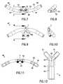
- FIGS. 7, 9 and FIG. 11 show three perspective views of a second embodiment of a nosepiece 42.
- the FIGS. 8 and 10 The second embodiment of the nose piece 42 differs only qualitatively from the embodiment of the nose piece 2.
- To reduce the noise emission nose piece 2 is bulbous, ie, the clear cross-sectional area increases from the hose connections to the tines stronger to. As a result, the flow velocity of the air is reduced in order to keep the noise emission low.
- the reduction of the flow resistance by increasing the cross-sectional area in the nosepiece is negligible because the flow resistance is largely determined by the thickness of forked tube 3.
- three prototypes are being prepared, each with a different increase in cross-sectional area. Measurement results are not available yet.
- Nose piece 42 comprises hose connections 44, hose transition regions 45, connecting pieces 47, tines 52 with annular nubs 53 and a central connecting piece 48 Fig. 11 detects, is located between hose transition areas 45 and hose connectors 44 each an inner radius stage 46, which compensates just the difference between the inner and outer radius of fork tube 3 in order to achieve the smoothest possible transition between the inner surface of the fork tube 3 and nose piece 42.
- the projections 32 may be removed or corresponding projections may be integrally formed on the inner surface of the nose piece 42.
- the transition areas 54 between tines 52 and connectors 47 are generously rounded to reduce noise emission.
- this radius outside is 4.3 mm.
- the outer diameter of the tines is 5.5 mm near the connector and 5 mm near the aperture.
- the wall thickness is about 0.5 mm.
- transition region between the central connector 48 and the tines 52 is also rounded, wherein the outer radius is also in the range between 4 and 5 mm.
- the recess 43 in the central connector 48 is in the FIGS. 8 and 10 on average and in Fig. 9 shown in a plan view. It serves to set a defined flow resistance between the left and right side of the nasal goggles. As in FIG. 1 shown, the goggles is mirror-symmetrical. This is also true in most cases for the user. As long as mirror symmetry is given, no air flows through the central connector 48. The symmetry can be broken, for example, that either the left or right forked tube 3 is bent or the user has runny nose and therefore a nostril swollen. In the former case, it is desirable on the one hand that both tines are supplied via the still open hose. On the other hand, the kinked fork hose is not completely closed.
- a pressure drop at the central connector 48 may be desirable. If a nostril is swollen, it is desirable to apply more air over the other prongs. Also in this case, air flow through the central connector 48 is desirable.
- Fig. 12 the Y-piece 4 is shown enlarged. It can be seen above the two fork hose connections 91 and below the supply hose connection 93.
- the Transition region 95 between the two fork tube connections is rounded and in one embodiment has a radius of 1 mm.
- the fork tubes and the supply hose have an inner radius (without protrusions 32) of 3 and 5 mm, respectively.
- the rounding of transition region 95 is particularly important if, for example, due to bending of a fork tube asymmetric flow conditions exist.
- All ports have inner radius stages 92 and 94 to compensate for the difference between inner radius and outer radius of the connected hoses.
- the inner radius stages may either have projections corresponding to the projections 32 in the connected hoses and / or the projections 32 may be removed at the hose ends.
Applications Claiming Priority (3)
| Application Number | Priority Date | Filing Date | Title |
|---|---|---|---|
| DE102005000922A DE102005000922A1 (de) | 2005-01-07 | 2005-01-07 | Luftbrille, Nasenstück, Y-Stück sowie Verfahren |
| EP07113959A EP1859831B1 (fr) | 2005-01-07 | 2005-12-30 | Canule nasale |
| EP05850200A EP1715909B1 (fr) | 2005-01-07 | 2005-12-30 | Canule nasale |
Related Parent Applications (4)
| Application Number | Title | Priority Date | Filing Date |
|---|---|---|---|
| EP05850200A Division EP1715909B1 (fr) | 2005-01-07 | 2005-12-30 | Canule nasale |
| EP05850200.6 Division | 2005-12-30 | ||
| EP07113959A Division EP1859831B1 (fr) | 2005-01-07 | 2005-12-30 | Canule nasale |
| EP07113959.6 Division | 2007-08-07 |
Publications (3)
| Publication Number | Publication Date |
|---|---|
| EP2374494A2 true EP2374494A2 (fr) | 2011-10-12 |
| EP2374494A3 EP2374494A3 (fr) | 2012-02-22 |
| EP2374494B1 EP2374494B1 (fr) | 2017-03-01 |
Family
ID=36127291
Family Applications (3)
| Application Number | Title | Priority Date | Filing Date |
|---|---|---|---|
| EP05850200A Active EP1715909B1 (fr) | 2005-01-07 | 2005-12-30 | Canule nasale |
| EP10186319.9A Active EP2374494B1 (fr) | 2005-01-07 | 2005-12-30 | Embout nasal pour lunette à air |
| EP07113959A Active EP1859831B1 (fr) | 2005-01-07 | 2005-12-30 | Canule nasale |
Family Applications Before (1)
| Application Number | Title | Priority Date | Filing Date |
|---|---|---|---|
| EP05850200A Active EP1715909B1 (fr) | 2005-01-07 | 2005-12-30 | Canule nasale |
Family Applications After (1)
| Application Number | Title | Priority Date | Filing Date |
|---|---|---|---|
| EP07113959A Active EP1859831B1 (fr) | 2005-01-07 | 2005-12-30 | Canule nasale |
Country Status (9)
| Country | Link |
|---|---|
| US (2) | US20090025723A1 (fr) |
| EP (3) | EP1715909B1 (fr) |
| JP (1) | JP5026281B2 (fr) |
| CN (1) | CN101098726B (fr) |
| AT (2) | ATE375178T1 (fr) |
| DE (4) | DE102005000922A1 (fr) |
| ES (3) | ES2359995T3 (fr) |
| PT (1) | PT2374494T (fr) |
| WO (1) | WO2006072231A2 (fr) |
Families Citing this family (58)
| Publication number | Priority date | Publication date | Assignee | Title |
|---|---|---|---|---|
| US7481219B2 (en) * | 2004-06-18 | 2009-01-27 | Mergenet Medical, Inc. | Medicine delivery interface system |
| WO2007019628A1 (fr) | 2005-08-15 | 2007-02-22 | Resmed Ltd | Ensemble generateur de flux de ventilation spontanee en pression positive continue et humidificateur a bas prix |
| DE102006019402A1 (de) * | 2006-04-24 | 2007-10-25 | Seleon Gmbh | Verfahren zur Steuerung eines TNI-Geräts sowie TNI-Gerät |
| GB0610171D0 (en) * | 2006-05-23 | 2006-06-28 | Robitaille Jean Pierre | Valved nasal canula |
| EP2079505B1 (fr) | 2006-11-08 | 2020-07-15 | ResMed Pty Ltd | Conduit destiné à être utilisé dans un appareil respiratoire |
| WO2008060587A2 (fr) * | 2006-11-15 | 2008-05-22 | Vapotherm, Inc. | Canule nasale à perte de chaleur réduite pour réduire le taux d'écoulement |
| US8196579B2 (en) * | 2007-08-29 | 2012-06-12 | Smiths Medical Asd, Inc. | Nose cannula heated/humidified gas delivery system |
| US8215301B2 (en) * | 2007-08-29 | 2012-07-10 | Smiths Medical Asd, Inc. | Nose cannula heated/humidified gas delivery system |
| WO2009049159A1 (fr) * | 2007-10-10 | 2009-04-16 | Parion Sciences, Inc. | Administration d'osmolytes par canule nasale |
| CA2713012A1 (fr) * | 2008-01-25 | 2009-07-30 | Salter Labs | Systeme de therapie respiratoire comprenant un ensemble canule nasale |
| DE102008010475A1 (de) | 2008-02-21 | 2009-08-27 | Seleon Gmbh | Applikatoren für eine Luftbrille |
| US9802022B2 (en) | 2008-03-06 | 2017-10-31 | Resmed Limited | Humidification of respiratory gases |
| DE102009047246A1 (de) * | 2008-12-01 | 2010-06-10 | Fisher & Paykel Healthcare Ltd., East Tamaki | Nasenkanüle |
| AU2010206053B2 (en) | 2009-07-31 | 2014-08-07 | ResMed Pty Ltd | Wire Heated Tube with Temperature Control System, Tube Type Detection, and Active Over Temperature Protection for Humidifier for Respiratory Apparatus |
| US8517729B2 (en) * | 2010-03-04 | 2013-08-27 | The University of Western Ontario and Trudell Medical International | Oral mouthpiece and method for the use thereof |
| US20110315148A1 (en) * | 2010-06-12 | 2011-12-29 | Widgerow Alan D | Skin adherent medical devices |
| US20110303224A1 (en) * | 2010-06-12 | 2011-12-15 | Widgerow Alan D | Skin adherent medical devices |
| US20120203127A1 (en) * | 2011-02-07 | 2012-08-09 | Slp Ltd. | Nasal cannula with integrated thermal flow sensing |
| WO2012170677A1 (fr) | 2011-06-07 | 2012-12-13 | Parion Sciences, Inc. | Procédés de traitement |
| US9308341B2 (en) * | 2011-08-04 | 2016-04-12 | Travis Ray NEELY | Oxygen delivery apparatus, system, and method |
| US9730830B2 (en) | 2011-09-29 | 2017-08-15 | Trudell Medical International | Nasal insert and cannula and methods for the use thereof |
| US8733348B2 (en) | 2011-09-30 | 2014-05-27 | Carefusion 207, Inc. | Humidifying respiratory gases |
| US9212673B2 (en) | 2011-09-30 | 2015-12-15 | Carefusion 207, Inc. | Maintaining a water level in a humidification component |
| US10168046B2 (en) | 2011-09-30 | 2019-01-01 | Carefusion 207, Inc. | Non-metallic humidification component |
| US9067036B2 (en) * | 2011-09-30 | 2015-06-30 | Carefusion 207, Inc. | Removing condensation from a breathing circuit |
| US9205220B2 (en) * | 2011-09-30 | 2015-12-08 | Carefusion 207, Inc. | Fluted heater wire |
| CN102688547A (zh) * | 2011-11-22 | 2012-09-26 | 河南科技大学 | 一种空气调节单元及由该单元组成的微型空气调节器 |
| USD665496S1 (en) * | 2011-12-06 | 2012-08-14 | Galemed Corporation | Nasal cannula |
| WO2013147623A1 (fr) | 2012-03-30 | 2013-10-03 | Dexter Chi Lun Cheung | Système d'humidification |
| US9272113B2 (en) | 2012-03-30 | 2016-03-01 | Carefusion 207, Inc. | Transporting liquid in a respiratory component |
| CN107596522B (zh) * | 2012-06-25 | 2021-08-31 | 费雪派克医疗保健有限公司 | 具有用于加湿和冷凝物管理的微结构的医疗部件 |
| KR101449920B1 (ko) | 2012-09-12 | 2014-10-08 | (주)유 바이오메드 | 호흡가스를 이용한 체온 조절용 호흡마스크 |
| US10300236B2 (en) * | 2012-10-31 | 2019-05-28 | Vapotherm, Inc. | Quiet nasal cannula |
| CN104902964A (zh) | 2012-11-27 | 2015-09-09 | 威廉马歇莱思大学 | 气泡式持续气道正压通气 |
| US9795756B2 (en) | 2012-12-04 | 2017-10-24 | Mallinckrodt Hospital Products IP Limited | Cannula for minimizing dilution of dosing during nitric oxide delivery |
| US9032959B2 (en) | 2012-12-04 | 2015-05-19 | Ino Therapeutics Llc | Cannula for minimizing dilution of dosing during nitric oxide delivery |
| CN104870042B (zh) * | 2012-12-20 | 2019-01-22 | 皇家飞利浦有限公司 | 用于呼吸治疗装置的内联适配器 |
| CN105025790B (zh) | 2013-01-08 | 2019-10-22 | 卡普尼亚公司 | 用于分析的呼吸选择 |
| NZ743034A (en) * | 2013-02-01 | 2019-12-20 | ResMed Pty Ltd | Wire heated tube with temperature control system for humidifier for respiratory apparatus |
| AU2014216297A1 (en) | 2013-02-12 | 2015-09-17 | Capnia, Inc. | Sampling and storage registry device for breath gas analysis |
| EP3546004B8 (fr) | 2013-03-14 | 2021-12-22 | Fisher & Paykel Healthcare Limited | Composants médicaux comportant des microstructures pour l'humidification et la gestion des condensats |
| CN109806478B (zh) * | 2013-03-15 | 2023-07-18 | 费雪派克医疗保健有限公司 | 鼻套管组件和相关部件 |
| US9561341B2 (en) * | 2013-05-17 | 2017-02-07 | Katarina Short | Humidification of ventilator gases |
| EP4035714A1 (fr) | 2013-08-09 | 2022-08-03 | Fisher & Paykel Healthcare Limited | Éléments d'alimentation nasale asymétriques et raccords pour interfaces nasales |
| US11191449B2 (en) | 2013-08-30 | 2021-12-07 | Capnia, Inc. | Neonatal carbon dioxide measurement system |
| BR112016004065A2 (pt) * | 2013-08-30 | 2017-09-12 | Capnia Inc | amostragem de gás por fluxo em coluna e sistema de medida |
| AU2014335018B2 (en) | 2013-10-16 | 2019-06-13 | Fisher & Paykel Healthcare Limited | A patient interface |
| DE102013017348B3 (de) * | 2013-10-18 | 2014-11-13 | Tni Medical Ag | Multifunktionaler, mobil einsatzfähiger Applikator |
| CN113144364A (zh) * | 2014-09-19 | 2021-07-23 | 费雪派克医疗保健有限公司 | 患者接口 |
| WO2016074722A1 (fr) | 2014-11-13 | 2016-05-19 | Tni Medical Ag | Applicateur multifonctionnel utilisable de manière mobile |
| CN108350620B (zh) | 2015-08-26 | 2020-03-24 | 必佳乐公司 | 具有传感器装置的用于驱动纺织机综框的驱动机构 |
| US11766537B2 (en) * | 2016-07-22 | 2023-09-26 | Fisher & Paykel Healthcare Limited | Sensing for respiratory circuits |
| USD870269S1 (en) | 2016-09-14 | 2019-12-17 | Fisher & Paykel Healthcare Limited | Nasal cannula assembly |
| DE202017001233U1 (de) | 2017-03-07 | 2017-05-22 | Norbert Neubauer | Gesichts - und Atemschale |
| US11110306B2 (en) * | 2018-01-05 | 2021-09-07 | Carlos Alberto Estrada Montoya | Portable device for heating the air that enters the nose of a user |
| DE202020001147U1 (de) | 2020-03-24 | 2020-04-15 | Norbert Neubauer | Filteraufnahme mit Augenschutz |
| DE202020001359U1 (de) | 2020-04-03 | 2020-04-22 | Norbert Neubauer | Atemmaske |
| DE202020001511U1 (de) | 2020-04-11 | 2020-05-07 | Norbert Neubauer | Schutzmaske |
Citations (1)
| Publication number | Priority date | Publication date | Assignee | Title |
|---|---|---|---|---|
| WO2002062413A2 (fr) | 2001-02-06 | 2002-08-15 | Seleon Gmbh | Appareil anti-ronflement, procede de reduction du ronflement, et lunettes a air |
Family Cites Families (48)
| Publication number | Priority date | Publication date | Assignee | Title |
|---|---|---|---|---|
| US2104266A (en) * | 1935-09-23 | 1938-01-04 | William J Mccormick | Means for the production and inhalation of tobacco fumes |
| US4682010A (en) * | 1983-03-07 | 1987-07-21 | Safeway Products, Inc. | In-line electric heater for an aerosol delivery system |
| GB2173274B (en) * | 1985-04-04 | 1989-02-01 | Boc Group Plc | Improvements in inhalation apparatus |
| AU581986B2 (en) * | 1985-05-22 | 1989-03-09 | Fisher & Paykel Healthcare Limited | Improvements in or relating to methods of and/or apparatus for humidifying gases |
| DD238922B1 (de) * | 1985-07-03 | 1989-10-04 | Schwarze Pumpe Gas Veb | Vorrichtung zur atemgasklimatisierung bei der intensivtherapie |
| US4738401A (en) * | 1987-02-24 | 1988-04-19 | Spraying Systems Co. | Quick disconnect nozzle assembly with twist-on spray tip |
| JPH034248Y2 (fr) * | 1987-09-16 | 1991-02-04 | ||
| JPH041954Y2 (fr) * | 1988-09-09 | 1992-01-23 | ||
| US4967744A (en) * | 1988-11-03 | 1990-11-06 | Airoflex Medical, Inc. | Flexible breathing circuit |
| US4989599A (en) * | 1989-01-26 | 1991-02-05 | Puritan-Bennett Corporation | Dual lumen cannula |
| JPH0340731U (fr) * | 1989-08-29 | 1991-04-18 | ||
| JPH04164458A (ja) * | 1990-10-26 | 1992-06-10 | Aika:Kk | 呼吸器用加温加湿装置 |
| JP2582720Y2 (ja) * | 1991-08-15 | 1998-10-08 | いすゞ自動車株式会社 | NOxセンサ |
| US5477852A (en) * | 1991-10-29 | 1995-12-26 | Airways Ltd., Inc. | Nasal positive airway pressure apparatus and method |
| JPH05296676A (ja) * | 1992-04-15 | 1993-11-09 | Ntc Kogyo Kk | 蓄熱装置 |
| JPH0623051A (ja) * | 1992-07-06 | 1994-02-01 | Toransumedo Kk | 加温加湿装置 |
| JPH06114003A (ja) * | 1992-10-07 | 1994-04-26 | Olympus Optical Co Ltd | 形状記憶合金を使用した長尺体湾曲駆動装置 |
| US5392770A (en) * | 1993-06-29 | 1995-02-28 | Clawson; Burrell E. | Tubing circuit systems for humidified respiratory gas |
| GB2284356B (en) * | 1993-11-22 | 1997-10-29 | Fisher & Paykel | Respiratory humidifier conduit |
| US5465728A (en) * | 1994-01-11 | 1995-11-14 | Phillips; Michael | Breath collection |
| US5513635A (en) * | 1995-02-02 | 1996-05-07 | Bedi; Shan | Nasal cannula anchoring apparatus |
| DE19617095C1 (de) * | 1996-04-29 | 1997-12-04 | Ruesch Willy Ag | Beheizbarer Beatmungsschlauch |
| ATE320829T1 (de) * | 1997-01-17 | 2006-04-15 | Ino Therapeutics Gmbh | Gesteuertes gasversorgungssystem |
| DE19746742A1 (de) * | 1997-10-23 | 1999-05-06 | Messer Austria Gmbh | Gasversorgungssystem für spontanatmende Patienten |
| US6167883B1 (en) * | 1998-01-23 | 2001-01-02 | Respiratory Support Products, Inc. | Medical air hose internal flow heater |
| AU4687600A (en) * | 1999-04-27 | 2000-11-10 | Loma Linda University Medical Center | Device and method for the administration of oxygen |
| AU4910900A (en) * | 1999-05-28 | 2000-12-18 | Euromedico Ltd. | Gas-supplying device |
| DE19942748A1 (de) * | 1999-09-08 | 2001-03-15 | Konrad Wirsich | Sauerstoffkateter mit Biegung im Nasenbereich |
| DE10007506B4 (de) * | 2000-02-18 | 2006-02-02 | Map Medizin-Technologie Gmbh | Atemgasschlauchanordnung zur Zufuhr eines Atemgases |
| BR0102116B1 (pt) * | 2000-05-10 | 2010-09-21 | componente para um membro de circuito de respiração. | |
| TW453865B (en) * | 2000-05-23 | 2001-09-11 | Optovent Ab | Apparatus and method for monitoring a patient's breath and supplying a gas or gases different from ambient air to the patient, and nose adapter for the apparatus |
| KR20020004630A (ko) | 2000-07-06 | 2002-01-16 | 정강훈 | 코러패드형 골판지 제조장치 |
| JP3420186B2 (ja) * | 2000-08-07 | 2003-06-23 | 株式会社東京興業貿易商会 | 医療用マスク |
| US6431172B1 (en) * | 2000-10-20 | 2002-08-13 | Mallinckrodt Inc. | Nasal cannula with inflatable plenum chamber |
| FR2827778B1 (fr) * | 2001-07-30 | 2004-05-28 | Vygon | Appareil nasal d'assistance respiratoire |
| US6679265B2 (en) * | 2001-10-25 | 2004-01-20 | Worldwide Medical Technologies | Nasal cannula |
| US7856981B2 (en) * | 2001-11-16 | 2010-12-28 | Fisher & Paykel Healthcare Limited | Nasal positive pressure device |
| AU2002362045A1 (en) * | 2001-12-04 | 2003-06-17 | Minnesota High-Tech Resources, Llc | Breathable gas mixtures to change body temperature |
| WO2003068301A1 (fr) * | 2002-02-15 | 2003-08-21 | Oridion Medical 1987 Ltd. | Canule nasale a double fonction |
| US7140367B2 (en) * | 2002-02-20 | 2006-11-28 | Fisher & Paykel Healtcare Limited | Conduit overheating detection system |
| US7024235B2 (en) * | 2002-06-20 | 2006-04-04 | University Of Florida Research Foundation, Inc. | Specially configured nasal pulse oximeter/photoplethysmography probes, and combined nasal probe/cannula, selectively with sampler for capnography, and covering sleeves for same |
| JP4162126B2 (ja) * | 2002-09-13 | 2008-10-08 | 宗行 石塚 | 酸素吸入装置 |
| DE10312881B3 (de) * | 2003-03-22 | 2004-05-06 | Drägerwerk AG | Atemgasschlauch für ein Atemgerät |
| DE10322964B4 (de) * | 2003-05-21 | 2006-03-23 | Seleon Gmbh | Steuergerät für Antischnarchgerät sowie Antischnarchgerät |
| US7493902B2 (en) * | 2003-05-30 | 2009-02-24 | Fisher & Paykel Healthcare Limited | Breathing assistance apparatus |
| WO2004105848A1 (fr) | 2003-05-30 | 2004-12-09 | E.M.E. (Electro Medical Equipment) Limited | Dispositifs de rechauffement pour tubes de respiration |
| US8225796B2 (en) * | 2003-07-28 | 2012-07-24 | Salter Labs | Respiratory therapy system including a nasal cannula assembly |
| US8196579B2 (en) * | 2007-08-29 | 2012-06-12 | Smiths Medical Asd, Inc. | Nose cannula heated/humidified gas delivery system |
-
2005
- 2005-01-07 DE DE102005000922A patent/DE102005000922A1/de not_active Withdrawn
- 2005-12-30 EP EP05850200A patent/EP1715909B1/fr active Active
- 2005-12-30 ES ES07113959T patent/ES2359995T3/es active Active
- 2005-12-30 EP EP10186319.9A patent/EP2374494B1/fr active Active
- 2005-12-30 DE DE502005010895T patent/DE502005010895D1/de active Active
- 2005-12-30 PT PT101863199T patent/PT2374494T/pt unknown
- 2005-12-30 EP EP07113959A patent/EP1859831B1/fr active Active
- 2005-12-30 WO PCT/DE2005/002335 patent/WO2006072231A2/fr active Application Filing
- 2005-12-30 CN CN2005800461666A patent/CN101098726B/zh active Active
- 2005-12-30 JP JP2007549791A patent/JP5026281B2/ja active Active
- 2005-12-30 ES ES10186319.9T patent/ES2621654T3/es active Active
- 2005-12-30 DE DE112005003491T patent/DE112005003491A5/de not_active Withdrawn
- 2005-12-30 AT AT05850200T patent/ATE375178T1/de active
- 2005-12-30 ES ES05850200T patent/ES2297769T3/es active Active
- 2005-12-30 US US11/920,100 patent/US20090025723A1/en not_active Abandoned
- 2005-12-30 DE DE502005001679T patent/DE502005001679D1/de active Active
- 2005-12-30 AT AT07113959T patent/ATE495779T1/de active
-
2007
- 2007-07-13 US US11/879,027 patent/US7775210B2/en active Active
Patent Citations (1)
| Publication number | Priority date | Publication date | Assignee | Title |
|---|---|---|---|---|
| WO2002062413A2 (fr) | 2001-02-06 | 2002-08-15 | Seleon Gmbh | Appareil anti-ronflement, procede de reduction du ronflement, et lunettes a air |
Non-Patent Citations (2)
| Title |
|---|
| "THE PHARYNGEAL CRITICAL PRESSURE THE WHYS AND HOWS OF USING NASAL CONTINUOUS POSITIVE AIRWAY PRESSURE DIAGNOSTICALLY", CHEST., vol. 110, October 1996 (1996-10-01), pages 1077 - 1088 |
| SLEEP, vol. 19, pages 184 - 188 |
Also Published As
| Publication number | Publication date |
|---|---|
| EP1715909B1 (fr) | 2007-10-10 |
| EP1859831B1 (fr) | 2011-01-19 |
| US7775210B2 (en) | 2010-08-17 |
| ES2621654T3 (es) | 2017-07-04 |
| CN101098726B (zh) | 2010-08-11 |
| CN101098726A (zh) | 2008-01-02 |
| WO2006072231A2 (fr) | 2006-07-13 |
| DE112005003491A5 (de) | 2007-12-06 |
| EP1859831A1 (fr) | 2007-11-28 |
| JP2008526328A (ja) | 2008-07-24 |
| ES2359995T3 (es) | 2011-05-30 |
| DE502005001679D1 (de) | 2007-11-22 |
| WO2006072231A3 (fr) | 2006-11-16 |
| DE102005000922A1 (de) | 2006-07-20 |
| ATE495779T1 (de) | 2011-02-15 |
| US20070283957A1 (en) | 2007-12-13 |
| EP2374494B1 (fr) | 2017-03-01 |
| ATE375178T1 (de) | 2007-10-15 |
| JP5026281B2 (ja) | 2012-09-12 |
| EP1715909A2 (fr) | 2006-11-02 |
| ES2297769T3 (es) | 2008-05-01 |
| DE502005010895D1 (de) | 2011-03-03 |
| EP2374494A3 (fr) | 2012-02-22 |
| PT2374494T (pt) | 2017-03-24 |
| US20090025723A1 (en) | 2009-01-29 |
Similar Documents
| Publication | Publication Date | Title |
|---|---|---|
| EP2374494B1 (fr) | Embout nasal pour lunette à air | |
| JP2023182779A (ja) | 医療用チューブおよびその製造方法 | |
| DE10322964B4 (de) | Steuergerät für Antischnarchgerät sowie Antischnarchgerät | |
| JP6005631B2 (ja) | 改良型呼吸管 | |
| DE112008003064T5 (de) | Nasenolive mit hochvolumiger Bypassströmung und Verfahren zu deren Verwendung | |
| US20130255677A1 (en) | Disposable respiratory circuit coupled with a disposable temperature sensor | |
| DE112011101485T5 (de) | Gerät zur Zuführung von Gasen zu einem Patienten | |
| DE112015001316T5 (de) | Medizinische Rohre für Beatmungssysteme | |
| EP1693081B9 (fr) | Echangeur de chaleur et d'humidité | |
| DE112015002892T5 (de) | Patientenschnittstelle und Bauteile | |
| EP2259829A1 (fr) | Applicateurs pour lunette à air | |
| GB2431359A (en) | Respirator tube heated by helical wire | |
| DE10331837B3 (de) | Gesichtsmaske für Beatmungsgeräte | |
| DE10021782B4 (de) | Vorrichtung zur Zufuhr eines Atemgases unter Überdruck | |
| EP1491226B1 (fr) | Méthode pour humidification du gaz respiratoire et dispositif respiratoire | |
| EP3852853B1 (fr) | Système d'assistance respiratoire | |
| EP3957347A1 (fr) | Respirateur pour l'oxygénothérapie à débit élevé | |
| EP2452717B1 (fr) | Système de tube respiratoire chauffé | |
| DE112022002439T5 (de) | Patientenschnittstelle | |
| CN218391830U (zh) | 一种围手术期专用的呼吸回路组合 | |
| DE102008005020A1 (de) | Geräuscharmes Anwendungsinterface mit integriertem PEEP-Ventil | |
| US20120060836A1 (en) | Patient circuit for improved support delivery |
Legal Events
| Date | Code | Title | Description |
|---|---|---|---|
| PUAI | Public reference made under article 153(3) epc to a published international application that has entered the european phase |
Free format text: ORIGINAL CODE: 0009012 |
|
| AC | Divisional application: reference to earlier application |
Ref document number: 1859831 Country of ref document: EP Kind code of ref document: P Ref document number: 1715909 Country of ref document: EP Kind code of ref document: P |
|
| AK | Designated contracting states |
Kind code of ref document: A2 Designated state(s): AT BE BG CH CY CZ DE DK EE ES FI FR GB GR HU IE IS IT LI LT LU LV MC NL PL PT RO SE SI SK TR |
|
| PUAL | Search report despatched |
Free format text: ORIGINAL CODE: 0009013 |
|
| AK | Designated contracting states |
Kind code of ref document: A3 Designated state(s): AT BE BG CH CY CZ DE DK EE ES FI FR GB GR HU IE IS IT LI LT LU LV MC NL PL PT RO SE SI SK TR |
|
| RIC1 | Information provided on ipc code assigned before grant |
Ipc: A61M 16/06 20060101AFI20120113BHEP |
|
| 17P | Request for examination filed |
Effective date: 20120817 |
|
| 17Q | First examination report despatched |
Effective date: 20151109 |
|
| GRAP | Despatch of communication of intention to grant a patent |
Free format text: ORIGINAL CODE: EPIDOSNIGR1 |
|
| INTG | Intention to grant announced |
Effective date: 20161011 |
|
| STAA | Information on the status of an ep patent application or granted ep patent |
Free format text: STATUS: GRANT OF PATENT IS INTENDED |
|
| GRAS | Grant fee paid |
Free format text: ORIGINAL CODE: EPIDOSNIGR3 |
|
| GRAA | (expected) grant |
Free format text: ORIGINAL CODE: 0009210 |
|
| STAA | Information on the status of an ep patent application or granted ep patent |
Free format text: STATUS: THE PATENT HAS BEEN GRANTED |
|
| AC | Divisional application: reference to earlier application |
Ref document number: 1715909 Country of ref document: EP Kind code of ref document: P Ref document number: 1859831 Country of ref document: EP Kind code of ref document: P |
|
| AK | Designated contracting states |
Kind code of ref document: B1 Designated state(s): AT BE BG CH CY CZ DE DK EE ES FI FR GB GR HU IE IS IT LI LT LU LV MC NL PL PT RO SE SI SK TR |
|
| REG | Reference to a national code |
Ref country code: GB Ref legal event code: FG4D Free format text: NOT ENGLISH |
|
| REG | Reference to a national code |
Ref country code: CH Ref legal event code: EP Ref country code: AT Ref legal event code: REF Ref document number: 870557 Country of ref document: AT Kind code of ref document: T Effective date: 20170315 |
|
| REG | Reference to a national code |
Ref country code: DE Ref legal event code: R082 Ref document number: 502005015529 Country of ref document: DE Representative=s name: ADVOTEC. PATENT- UND RECHTSANWALTSPARTNERSCHAF, DE Ref country code: DE Ref legal event code: R082 Ref document number: 502005015529 Country of ref document: DE Representative=s name: ADVOTEC. PATENT- UND RECHTSANWAELTE, DE |
|
| REG | Reference to a national code |
Ref country code: IE Ref legal event code: FG4D Free format text: LANGUAGE OF EP DOCUMENT: GERMAN |
|
| REG | Reference to a national code |
Ref country code: PT Ref legal event code: SC4A Ref document number: 2374494 Country of ref document: PT Date of ref document: 20170324 Kind code of ref document: T Free format text: AVAILABILITY OF NATIONAL TRANSLATION Effective date: 20170316 |
|
| REG | Reference to a national code |
Ref country code: DE Ref legal event code: R096 Ref document number: 502005015529 Country of ref document: DE Ref country code: CH Ref legal event code: NV Representative=s name: PATWIL AG, CH |
|
| REG | Reference to a national code |
Ref country code: NL Ref legal event code: FP |
|
| REG | Reference to a national code |
Ref country code: ES Ref legal event code: FG2A Ref document number: 2621654 Country of ref document: ES Kind code of ref document: T3 Effective date: 20170704 |
|
| REG | Reference to a national code |
Ref country code: LT Ref legal event code: MG4D |
|
| PG25 | Lapsed in a contracting state [announced via postgrant information from national office to epo] |
Ref country code: GR Free format text: LAPSE BECAUSE OF FAILURE TO SUBMIT A TRANSLATION OF THE DESCRIPTION OR TO PAY THE FEE WITHIN THE PRESCRIBED TIME-LIMIT Effective date: 20170602 Ref country code: LT Free format text: LAPSE BECAUSE OF FAILURE TO SUBMIT A TRANSLATION OF THE DESCRIPTION OR TO PAY THE FEE WITHIN THE PRESCRIBED TIME-LIMIT Effective date: 20170301 Ref country code: FI Free format text: LAPSE BECAUSE OF FAILURE TO SUBMIT A TRANSLATION OF THE DESCRIPTION OR TO PAY THE FEE WITHIN THE PRESCRIBED TIME-LIMIT Effective date: 20170301 |
|
| PG25 | Lapsed in a contracting state [announced via postgrant information from national office to epo] |
Ref country code: SE Free format text: LAPSE BECAUSE OF FAILURE TO SUBMIT A TRANSLATION OF THE DESCRIPTION OR TO PAY THE FEE WITHIN THE PRESCRIBED TIME-LIMIT Effective date: 20170301 Ref country code: BG Free format text: LAPSE BECAUSE OF FAILURE TO SUBMIT A TRANSLATION OF THE DESCRIPTION OR TO PAY THE FEE WITHIN THE PRESCRIBED TIME-LIMIT Effective date: 20170601 Ref country code: LV Free format text: LAPSE BECAUSE OF FAILURE TO SUBMIT A TRANSLATION OF THE DESCRIPTION OR TO PAY THE FEE WITHIN THE PRESCRIBED TIME-LIMIT Effective date: 20170301 |
|
| PG25 | Lapsed in a contracting state [announced via postgrant information from national office to epo] |
Ref country code: EE Free format text: LAPSE BECAUSE OF FAILURE TO SUBMIT A TRANSLATION OF THE DESCRIPTION OR TO PAY THE FEE WITHIN THE PRESCRIBED TIME-LIMIT Effective date: 20170301 Ref country code: SK Free format text: LAPSE BECAUSE OF FAILURE TO SUBMIT A TRANSLATION OF THE DESCRIPTION OR TO PAY THE FEE WITHIN THE PRESCRIBED TIME-LIMIT Effective date: 20170301 Ref country code: CZ Free format text: LAPSE BECAUSE OF FAILURE TO SUBMIT A TRANSLATION OF THE DESCRIPTION OR TO PAY THE FEE WITHIN THE PRESCRIBED TIME-LIMIT Effective date: 20170301 Ref country code: RO Free format text: LAPSE BECAUSE OF FAILURE TO SUBMIT A TRANSLATION OF THE DESCRIPTION OR TO PAY THE FEE WITHIN THE PRESCRIBED TIME-LIMIT Effective date: 20170301 |
|
| PG25 | Lapsed in a contracting state [announced via postgrant information from national office to epo] |
Ref country code: PL Free format text: LAPSE BECAUSE OF FAILURE TO SUBMIT A TRANSLATION OF THE DESCRIPTION OR TO PAY THE FEE WITHIN THE PRESCRIBED TIME-LIMIT Effective date: 20170301 Ref country code: IS Free format text: LAPSE BECAUSE OF FAILURE TO SUBMIT A TRANSLATION OF THE DESCRIPTION OR TO PAY THE FEE WITHIN THE PRESCRIBED TIME-LIMIT Effective date: 20170701 |
|
| REG | Reference to a national code |
Ref country code: DE Ref legal event code: R097 Ref document number: 502005015529 Country of ref document: DE |
|
| REG | Reference to a national code |
Ref country code: FR Ref legal event code: PLFP Year of fee payment: 13 |
|
| PLBE | No opposition filed within time limit |
Free format text: ORIGINAL CODE: 0009261 |
|
| STAA | Information on the status of an ep patent application or granted ep patent |
Free format text: STATUS: NO OPPOSITION FILED WITHIN TIME LIMIT |
|
| PG25 | Lapsed in a contracting state [announced via postgrant information from national office to epo] |
Ref country code: DK Free format text: LAPSE BECAUSE OF FAILURE TO SUBMIT A TRANSLATION OF THE DESCRIPTION OR TO PAY THE FEE WITHIN THE PRESCRIBED TIME-LIMIT Effective date: 20170301 |
|
| PGFP | Annual fee paid to national office [announced via postgrant information from national office to epo] |
Ref country code: NL Payment date: 20171219 Year of fee payment: 13 |
|
| 26N | No opposition filed |
Effective date: 20171204 |
|
| PG25 | Lapsed in a contracting state [announced via postgrant information from national office to epo] |
Ref country code: SI Free format text: LAPSE BECAUSE OF FAILURE TO SUBMIT A TRANSLATION OF THE DESCRIPTION OR TO PAY THE FEE WITHIN THE PRESCRIBED TIME-LIMIT Effective date: 20170301 |
|
| PGFP | Annual fee paid to national office [announced via postgrant information from national office to epo] |
Ref country code: CH Payment date: 20171221 Year of fee payment: 13 Ref country code: IT Payment date: 20171218 Year of fee payment: 13 |
|
| PGFP | Annual fee paid to national office [announced via postgrant information from national office to epo] |
Ref country code: ES Payment date: 20180105 Year of fee payment: 13 |
|
| PG25 | Lapsed in a contracting state [announced via postgrant information from national office to epo] |
Ref country code: LU Free format text: LAPSE BECAUSE OF NON-PAYMENT OF DUE FEES Effective date: 20171230 |
|
| REG | Reference to a national code |
Ref country code: IE Ref legal event code: MM4A |
|
| REG | Reference to a national code |
Ref country code: BE Ref legal event code: MM Effective date: 20171231 |
|
| PG25 | Lapsed in a contracting state [announced via postgrant information from national office to epo] |
Ref country code: IE Free format text: LAPSE BECAUSE OF NON-PAYMENT OF DUE FEES Effective date: 20171230 |
|
| PG25 | Lapsed in a contracting state [announced via postgrant information from national office to epo] |
Ref country code: BE Free format text: LAPSE BECAUSE OF NON-PAYMENT OF DUE FEES Effective date: 20171231 |
|
| PG25 | Lapsed in a contracting state [announced via postgrant information from national office to epo] |
Ref country code: PT Free format text: LAPSE BECAUSE OF NON-PAYMENT OF DUE FEES Effective date: 20181001 |
|
| REG | Reference to a national code |
Ref country code: AT Ref legal event code: MM01 Ref document number: 870557 Country of ref document: AT Kind code of ref document: T Effective date: 20171230 |
|
| PG25 | Lapsed in a contracting state [announced via postgrant information from national office to epo] |
Ref country code: AT Free format text: LAPSE BECAUSE OF NON-PAYMENT OF DUE FEES Effective date: 20171230 |
|
| PG25 | Lapsed in a contracting state [announced via postgrant information from national office to epo] |
Ref country code: MC Free format text: LAPSE BECAUSE OF FAILURE TO SUBMIT A TRANSLATION OF THE DESCRIPTION OR TO PAY THE FEE WITHIN THE PRESCRIBED TIME-LIMIT Effective date: 20170301 Ref country code: HU Free format text: LAPSE BECAUSE OF FAILURE TO SUBMIT A TRANSLATION OF THE DESCRIPTION OR TO PAY THE FEE WITHIN THE PRESCRIBED TIME-LIMIT; INVALID AB INITIO Effective date: 20051230 |
|
| REG | Reference to a national code |
Ref country code: CH Ref legal event code: PL |
|
| REG | Reference to a national code |
Ref country code: NL Ref legal event code: MM Effective date: 20190101 |
|
| PG25 | Lapsed in a contracting state [announced via postgrant information from national office to epo] |
Ref country code: NL Free format text: LAPSE BECAUSE OF NON-PAYMENT OF DUE FEES Effective date: 20190101 |
|
| PG25 | Lapsed in a contracting state [announced via postgrant information from national office to epo] |
Ref country code: CY Free format text: LAPSE BECAUSE OF NON-PAYMENT OF DUE FEES Effective date: 20170301 Ref country code: IT Free format text: LAPSE BECAUSE OF NON-PAYMENT OF DUE FEES Effective date: 20181230 |
|
| PG25 | Lapsed in a contracting state [announced via postgrant information from national office to epo] |
Ref country code: CH Free format text: LAPSE BECAUSE OF NON-PAYMENT OF DUE FEES Effective date: 20181231 Ref country code: LI Free format text: LAPSE BECAUSE OF NON-PAYMENT OF DUE FEES Effective date: 20181231 |
|
| REG | Reference to a national code |
Ref country code: ES Ref legal event code: FD2A Effective date: 20200205 |
|
| PG25 | Lapsed in a contracting state [announced via postgrant information from national office to epo] |
Ref country code: ES Free format text: LAPSE BECAUSE OF NON-PAYMENT OF DUE FEES Effective date: 20181231 |
|
| P01 | Opt-out of the competence of the unified patent court (upc) registered |
Effective date: 20230529 |
|
| PGFP | Annual fee paid to national office [announced via postgrant information from national office to epo] |
Ref country code: GB Payment date: 20231220 Year of fee payment: 19 |
|
| PGFP | Annual fee paid to national office [announced via postgrant information from national office to epo] |
Ref country code: FR Payment date: 20231220 Year of fee payment: 19 |
|
| PGFP | Annual fee paid to national office [announced via postgrant information from national office to epo] |
Ref country code: DE Payment date: 20240220 Year of fee payment: 19 |