EP2374045B1 - Reprografisches system - Google Patents
Reprografisches system Download PDFInfo
- Publication number
- EP2374045B1 EP2374045B1 EP09774655.6A EP09774655A EP2374045B1 EP 2374045 B1 EP2374045 B1 EP 2374045B1 EP 09774655 A EP09774655 A EP 09774655A EP 2374045 B1 EP2374045 B1 EP 2374045B1
- Authority
- EP
- European Patent Office
- Prior art keywords
- sensor
- actuator
- network
- printing
- temperature
- Prior art date
- Legal status (The legal status is an assumption and is not a legal conclusion. Google has not performed a legal analysis and makes no representation as to the accuracy of the status listed.)
- Withdrawn - After Issue
Links
- 238000007639 printing Methods 0.000 claims description 29
- 238000009826 distribution Methods 0.000 claims description 26
- 238000012545 processing Methods 0.000 claims description 14
- 238000010438 heat treatment Methods 0.000 claims description 7
- 238000000034 method Methods 0.000 description 13
- 230000006399 behavior Effects 0.000 description 8
- 230000003044 adaptive effect Effects 0.000 description 7
- 238000013459 approach Methods 0.000 description 7
- 230000001276 controlling effect Effects 0.000 description 5
- 101000767160 Saccharomyces cerevisiae (strain ATCC 204508 / S288c) Intracellular protein transport protein USO1 Proteins 0.000 description 3
- 238000013528 artificial neural network Methods 0.000 description 3
- 239000003086 colorant Substances 0.000 description 3
- 238000013461 design Methods 0.000 description 3
- 230000000694 effects Effects 0.000 description 2
- 238000005259 measurement Methods 0.000 description 2
- 238000004088 simulation Methods 0.000 description 2
- 238000012360 testing method Methods 0.000 description 2
- 238000012546 transfer Methods 0.000 description 2
- 238000007476 Maximum Likelihood Methods 0.000 description 1
- 238000013473 artificial intelligence Methods 0.000 description 1
- 235000000332 black box Nutrition 0.000 description 1
- 238000006243 chemical reaction Methods 0.000 description 1
- 238000004891 communication Methods 0.000 description 1
- 238000010586 diagram Methods 0.000 description 1
- 238000005516 engineering process Methods 0.000 description 1
- 230000007613 environmental effect Effects 0.000 description 1
- 238000002474 experimental method Methods 0.000 description 1
- 239000000463 material Substances 0.000 description 1
- 230000001105 regulatory effect Effects 0.000 description 1
- 238000011160 research Methods 0.000 description 1
- 230000035945 sensitivity Effects 0.000 description 1
- 230000003068 static effect Effects 0.000 description 1
- 230000002123 temporal effect Effects 0.000 description 1
- 238000012549 training Methods 0.000 description 1
Images


Classifications
-
- G—PHYSICS
- G03—PHOTOGRAPHY; CINEMATOGRAPHY; ANALOGOUS TECHNIQUES USING WAVES OTHER THAN OPTICAL WAVES; ELECTROGRAPHY; HOLOGRAPHY
- G03G—ELECTROGRAPHY; ELECTROPHOTOGRAPHY; MAGNETOGRAPHY
- G03G15/00—Apparatus for electrographic processes using a charge pattern
- G03G15/50—Machine control of apparatus for electrographic processes using a charge pattern, e.g. regulating differents parts of the machine, multimode copiers, microprocessor control
- G03G15/5004—Power supply control, e.g. power-saving mode, automatic power turn-off
-
- G—PHYSICS
- G03—PHOTOGRAPHY; CINEMATOGRAPHY; ANALOGOUS TECHNIQUES USING WAVES OTHER THAN OPTICAL WAVES; ELECTROGRAPHY; HOLOGRAPHY
- G03G—ELECTROGRAPHY; ELECTROPHOTOGRAPHY; MAGNETOGRAPHY
- G03G15/00—Apparatus for electrographic processes using a charge pattern
- G03G15/50—Machine control of apparatus for electrographic processes using a charge pattern, e.g. regulating differents parts of the machine, multimode copiers, microprocessor control
- G03G15/5075—Remote control machines, e.g. by a host
-
- G—PHYSICS
- G03—PHOTOGRAPHY; CINEMATOGRAPHY; ANALOGOUS TECHNIQUES USING WAVES OTHER THAN OPTICAL WAVES; ELECTROGRAPHY; HOLOGRAPHY
- G03G—ELECTROGRAPHY; ELECTROPHOTOGRAPHY; MAGNETOGRAPHY
- G03G15/00—Apparatus for electrographic processes using a charge pattern
- G03G15/55—Self-diagnostics; Malfunction or lifetime display
-
- G—PHYSICS
- G03—PHOTOGRAPHY; CINEMATOGRAPHY; ANALOGOUS TECHNIQUES USING WAVES OTHER THAN OPTICAL WAVES; ELECTROGRAPHY; HOLOGRAPHY
- G03G—ELECTROGRAPHY; ELECTROPHOTOGRAPHY; MAGNETOGRAPHY
- G03G2215/00—Apparatus for electrophotographic processes
- G03G2215/00362—Apparatus for electrophotographic processes relating to the copy medium handling
- G03G2215/00535—Stable handling of copy medium
- G03G2215/00717—Detection of physical properties
- G03G2215/00772—Detection of physical properties of temperature influencing copy sheet handling
-
- G—PHYSICS
- G03—PHOTOGRAPHY; CINEMATOGRAPHY; ANALOGOUS TECHNIQUES USING WAVES OTHER THAN OPTICAL WAVES; ELECTROGRAPHY; HOLOGRAPHY
- G03G—ELECTROGRAPHY; ELECTROPHOTOGRAPHY; MAGNETOGRAPHY
- G03G2215/00—Apparatus for electrophotographic processes
- G03G2215/20—Details of the fixing device or porcess
- G03G2215/2003—Structural features of the fixing device
- G03G2215/2045—Variable fixing speed
Definitions
- the invention relates to a reprographic system comprising at least one sensor, providing a sensor signal, at least one actuator, responsive to an actuator signal, and a control unit for generating the actuator signal for the at least one actuator in dependence of the sensor signal of the at least one sensor
- Adaptive control as such is known in the art. In this respect adaptability is defined as a dynamic in-product trade-off between characteristics of the system at system level.
- modelreference adaptive control uses a reference model that reflects the desired behaviour of the system. On the basis of the output of the reference model and the observations, the controller is tuned.
- STC self-tuning controllers
- EP1847887 discloses to lower the processing speed when the mains connection cannot deliver sufficient power.
- a classical control approach is used herein.
- US5683605 discloses a heater controlling unit in a heat fusing device of reprographic machine that makes use of a fuzzy neural network. This has advantages as indicated before.
- control unit comprises a signal processing module for generating the actuator signal based on at least one sensor signal with involvement of a probabilistic network.
- the invention is related to the use of probabilistic estimators for machine control, in particular for engine control for a printer. This is done by setting up a probabilistic model, training the model with realistic data and using the model for control.
- Usage of these kind of models is advantageous, since it allows to derive control rules in a probabilistic manner: control as close to a certain value as possible, or control such that the control value crosses in less than x% a certain threshold. It provides a control that by its nature is able to adapt to various circumstances.
- the probabilistic network is a Bayesian network.
- Bayesian networks are around for awhile by now, and have seen a remarkable rise in their popularity within the scientific community during the past decade.
- researchers from various application areas such as psychology, biomedicine and finance have applied these techniques successfully.
- little research has been done in order to apply these techniques.
- We believe that these techniques may be useful when system-wide decisions have to be made during runtime, e.g., when the system has to dynamically adapt itself to the environment.
- Bayesian networks to tune parameters of controllers of the system, which is applied to an adaptive control of a part of a printing system.
- Bayesian networks contains a qualitative part which can be constructed using expert knowledge, i.e., it is understandable.
- the quantitative part of a Bayesian network can be learned from data, which makes it possible to calculate the desired control signal.
- the availability of probabilities makes it possible to control the system in such a way that truly undesired states can be avoided with high probability.
- Productivity improves compared to rule-based systems.
- the logic of the controller you get for free.
- the senor is a temperature sensor for sensing the temperature of a copy sheet and the actuator is a heating component.
- An example of an application for this invention is the control of paper temperature.
- you can derive rules such that your paper will always (e.g. 99% of the cases) be warmer than e.g. 80 degC.
- the controller will adapt itself: when the paper is very light weight, it will make sure that the paper temperature is higher such that it can cope with a certain switch to heavy paper, while, when the paper is heavy, it will use less margin. This feature is very effective in minimising the needed latitude.
- the reprographic system where the system is a printing system, having a printing speed, the sensor is a sensor for determining the power available and the actuator is an actuator for controlling the requested power by controlling the printing speed.
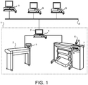
- Fig. 1 is a schematic diagram of an environment in which the present invention may be used.
- the reprographic system 1 as presented here comprises a scanning unit 2, a printing unit 3 and a control unit 4.
- the scanning unit 2 is provided for scanning an original colour document supported on a support material.
- the scanning unit is provided with a CCD type colour image sensor (i.e. a photoelectric conversion device) which converts the reflected light into electric signals corresponding to the primary colours red (R), green (G) and blue (B).
- a local user interface panel 5 is provided for starting scan and copy operations.
- the printing unit 3 is provided for printing digital images on image supports.
- the printing unit may use any number of printing techniques. It may be a thermal or piezoelectric inkjet printer, a pen plotter, or a press system based on organic photoconductor technology, for instance.
- printing is achieved using an electrophotographic printing process with a transfer belt and a fuse roll. An image is projected on a photosensitive drum which will be charged accordingly, the image on the drum is provided with toner and next the image is transferred to a transfer belt and subsequently fused on a paper sheet in a fuse pinch.
- a local user interface panel 6 is provided with input means such as buttons for selecting a user, a job a and starting a printing operation etc.
- the scanning unit 2 and the printing unit 3 are both connected to a control unit 4.
- the control unit 4 executes various tasks such as receiving input data from the scanning unit 2, handling and scheduling the submitted data files, controlling the scanning unit 2 and the printing unit 3, converting image data into printable data etc.
- the control unit is provided with a user interface panel 7 for offering the operator an extensive menu of commands for executing tasks and making settings.
- control unit is connected to a network 8 so that a number of client computers 9, also connected to the network, may make use of the reprographic system 1.
- the reprographic system is depicted in Fig. 1 as three distinct apparatuses: scanner, printer and control unit, however it equally possible to combine these three components in one reprographic apparatus.
- control unit 4 of the reprographic system 1 comprises a Central Processing Unit (CPU) 40, a Random Access Memory (RAM) 48, a Read Only Memory (ROM) 60, a network card 46, an interface card 47, a hard disk (HD) 50, an image processing unit 54 (such as a Raster Image Processor or RIP) and a signal processing unit 55.
- CPU Central Processing Unit
- RAM Random Access Memory
- ROM Read Only Memory
- HD hard disk
- image processing unit 54 such as a Raster Image Processor or RIP
- signal processing unit 55 such as a Raster Image Processor or RIP
- the CPU 40 controls the respective units of the control unit 4, the local user interface 7, scanning unit 2 and the printing unit engine 3, in accordance with control programs stored on the ROM 60 or on the HD 50.
- the ROM 60 stores programs and data such as boot program, set-up program, various set-up data or the like, which are to be read out and executed by the CPU 40.
- the hard disk 50 is an example of a storage unit for storing and saving programs and data which make the CPU 40 execute a print process to be described later.
- the hard disk 50 also comprises an area for saving the data of externally submitted print jobs.
- the programs and data on the HD 50 are read out onto the RAM 48 by the CPU 40 as needed.
- the RAM 48 has an area for temporarily storing the programs and data read out from the ROM 60 and HD 50 by the CPU 40, and a work area which is used by the CPU 40 to execute various processes.
- Interface card 47 connects the control unit to scanning unit 2 and printing unit 3.
- Network card 46 connects the control unit 4 to the network 8 and is designed to provide communication with the workstations 9, and with other devices reachable via the network.
- the signal processing unit 55 may be implemented either as a software component of an operating system running on the control unit 52 or as a firmware program executed on the CPU 40.
- a digital image is assembled in the form of a raster image file.
- a raster image file is generally defined to be a rectangular array of regularly sampled values, known as pixels. Each pixel (picture element) has one or more numbers associated with it, generally specifying a colour which the pixel should be displayed in.
- the representation of an image may have each pixel specified by three 8 bit (24 bits total) colorimetric values (ranging from 0-255) defining the amount of R, G, and B respectively in each pixel. In the right proportions, R, G, and B can be combined to form black, white, 254 shades of grey, and a vast array of colours (about 16 millions).
- the digital image obtained by the scanning unit 2 may be stored on a memory of the controller 6 and be handled according to a copy path, wherein the image is printed by the print engine 4.
- the digital image may be transferred from the controller to a client computer 9 (scan-to-file path).
- a user of the client computer 9 may decide to print a digital image, which reflects the printing mode of operation of the system.
- the signal processing unit that controls system characteristics of the reprographic system uses a Bayesian network to determine actuator signals based on incoming sensor signals.
- Bayesian networks can encode various probability distributions. Most often the variables are either all discrete or all continuous. Hybrid Bayesian networks, however, contain both discrete and continuous conditional probability distributions. A commonly used type of hybrid Bayesian network is the conditional linear Gaussian model. Efficient exact and approximate algorithms have been developed to infer probabilities from such networks. A Bayesian network can be constructed with the help of one or more domain experts. However, building Bayesian networks using expert knowledge, although by now known to be feasible for some domains, can be very tedious and time consuming.
- a Bayesian network is a Bayesian network where the vertices of the graph are indexed with (discrete) time slices. Each time slice consists of a static Bayesian network and the time slices are linked to represent the relationships between states in time.
- the topology of a Bayesian network is established a priori during the design phase of the reprographic apparatus for each characteristic of the apparatus where adaptibility is required.
- parameter learning takes place.
- this is also carried out during the design of the apparatus.
- the targetted hardware is modelled and this model is used to infer the associated joint probability distribution for the given network topology. It is remarked however that this latter step is carried out at runtime when the reprographic system is actually in use.
- the topology and the probability distribution data obtained are stored on the hard disk of the control unit and will be invoked at the moment the signal processing unit is required to act according to the invention.
- a controller target can be either stated as “keep the temperature as close as possible to a certain value” or as “regulate the temperature such that its probability to decrease to a certain value is less than x%".
- the second option leads to a kind of smart buffer behavior: for light paper, the temperature is regulated at a higher set point in order to account for the possibility that heavier paper will arrive.
- the qualitative structure of the domain has been elicited from the domain experts. For the purpose of clarity, we focus on certain relevant parts of the complete network dealing with the specific problem of determining the correct setpoint of the heater.
- the structure of the domain consisting of two time slices is presented in Figure 3 .
- Fig. 4 shows the operative environment for this control.
- the associated random variables for this network have been modeled as discrete variables by discretising the values to typical values that can be found during simulation.
- the setpoint variables has a domainsize of 12; media (e.g. paper) temperature has a domainsize of 16 and we consider three paper types: 80, 120 or 160 grams paper.
- a physical model of the system will be created, e.g.
- the signal processing unit controls the setpoint for the heater. As input it uses the temperature of the heater obtained from a sensor at the heater and paper weight obtained from the job definition of the print job that is actually carried out.
- the signal processing unit according to the invention making use of a Bayesian network, is used to control the setpoint of this controller.
- the probablisitic network is extended to incorporate additional evidence of earlier states. In the alternative it is possible to sample less, i.e., by waiting to the system returns to a steady state.
- a lowest temperature is put as a probability constraint on the control signal.
- the effect is that in order to get high quality prints, a certain amount of heat is available at any time.
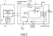
- the productivity of printers is limited to the amount of power available, in particular in environments which depend on weak mains. If there is insufficient power available, then setpoints cannot be reached, which causes bad print quality. To overcome this problem the embodiment presented implements dynamic speed adjustment using a Bayesian network.
- Fig. 7 Shown is a sensor for available power and a sensor for velocity.
- Motor M drives the photosensitive drum with a velocity v, being the printing speed.
- the available power is by means of a sensor communicated to the signal processing unit.
- the requested power is known. This may result in an error.
- Velocity is controlled to minimize the error.
- the signal processing unit generates the setpoint for velocity based on the inputs and by making use of a Bayesian network. In this way the requested power is controlled by controlling the printing speed.
- the topology of the Bayesian network on each time slice for this embodiment is shown in Figure 8 .
- the requested power available is an observable variable that depends on lower-level controllers that aim at maintaining the right setpoint for reaching a good print quality.
- the error variable is only observable in laboratory situations and models the deviation of the actual temperature from the ideal temperature. If this error variable exceeds a certain threshold, then the print quality will be below a certain norm. Both velocity and available power influence the power that is or can be requested by the low-level controllers. Furthermore, the combination of the available power and the requested power is a good predictor of the error according to the domain experts.
- two time slices are used with the interconnections between the available power - which models that the power supply on different time slices is not independent - and requested power, which models the state of the machine that influences the requested power.
- the variables are modeled as Gaussian variables. This is reasonable as most variables are normally distributed, except for the available power (see Figure 9 ). Fitting a Gaussian random variable to such a distribution will typically lead to insufficient performance. However, it can be seen as a sum of two Gaussian distribution, one around 400W and a second around 1500W with a small variance.
- Such a distribution can be modeled using a hybrid network.
- One of the main reasoning tasks of the network is to estimate the error given a certain velocity and a certain observations.
- the advantage of the discrete version is that the probability distribution can easily be inspected and it has no underlying assumptions about the distribution, which makes it easier to use in practice.
- the hybrid version however allows for more efficient computation as we need a large number of discrete to describe the conditional distributions. For this reason, we used the latter in experiments.
- the available power is modeled as a random variable with a mean of 600W and a standard deviation of 200W.
- the available power given to the system is sampled from this variable every 100 seconds.
- the marginal probability distribution of the error in the next time slice is computed.
- This error is a Gaussian random variable with mean ⁇ and standard deviation ⁇ . For Gaussian variables more than 99.7% of the real value of the error will be within three standard deviations of the mean.
Landscapes
- Engineering & Computer Science (AREA)
- Microelectronics & Electronic Packaging (AREA)
- Physics & Mathematics (AREA)
- General Physics & Mathematics (AREA)
- Control Or Security For Electrophotography (AREA)
- Accessory Devices And Overall Control Thereof (AREA)
Claims (5)
- Reprografisches System (1) mit wenigstens einem Sensor, der ein Sensorsignal liefert, wenigstens einem Aktuator, der auf ein Aktuatorsignal anspricht, und einer Steuereinheit (4) zum Erzeugen des Aktuatorsignals für den wenigstens einen Aktuator in Abhängigkeit von dem Sensorsignal des wenigstens einen Sensors, dadurch gekennzeichnet, dass die Steuereinheit ein Signalverarbeitungsmodul aufweist zum Erzeugen des Aktuatorsignals auf der Grundlage wenigstens eines Sensorsignals unter Verwendung eines probabilistischen Netzwerkes, das ein probabilistisches Modell zum Steuern eines Einstellwertes enthält, um das System dynamisch an die Umgebung anzupassen, in der das System verwendet wird.
- System nach Anspruch 1, bei dem das probabilistisches Netzwerk ein Bayessches Netzwerk ist.
- System nach Anspruch 1, bei dem das System ein Druckersystem ist, der Sensor ein Temperatursensor zum Erfassen der Temperatur einer wärmeerzeugenden Komponente ist, und der Aktuator eine wärmeerzeugende Komponente ist.
- System nach Anspruch 1, bei dem das System ein Druckersystem ist, das eine Druckgeschwindigkeit hat, der Sensor ein Sensor zum Bestimmen einer verfügbaren Leistung ist, und der Aktuator ein Aktuator zur Steuerung der geforderten Leistung durch Steuerung der Druckgeschwindigkeit ist.
- System nach Anspruch 2 - 4, mit einer Speichereinrichtung zur Speicherung einer Topologie eines Bayesschen Netzwerkes, wobei die Topologie Knoten und Kanten enthält, und zur Speicherung von Wahrscheinlichkeitsverteilungen, die eins zu eins mit den Knoten gekoppelt sind.
Applications Claiming Priority (2)
| Application Number | Priority Date | Filing Date | Title |
|---|---|---|---|
| US11959108P | 2008-12-03 | 2008-12-03 | |
| PCT/EP2009/066348 WO2010063800A1 (en) | 2008-12-03 | 2009-12-03 | Reprographic system |
Publications (2)
| Publication Number | Publication Date |
|---|---|
| EP2374045A1 EP2374045A1 (de) | 2011-10-12 |
| EP2374045B1 true EP2374045B1 (de) | 2019-02-20 |
Family
ID=41508414
Family Applications (1)
| Application Number | Title | Priority Date | Filing Date |
|---|---|---|---|
| EP09774655.6A Withdrawn - After Issue EP2374045B1 (de) | 2008-12-03 | 2009-12-03 | Reprografisches system |
Country Status (4)
| Country | Link |
|---|---|
| US (1) | US8437034B2 (de) |
| EP (1) | EP2374045B1 (de) |
| JP (1) | JP5676465B2 (de) |
| WO (1) | WO2010063800A1 (de) |
Families Citing this family (4)
| Publication number | Priority date | Publication date | Assignee | Title |
|---|---|---|---|---|
| US8314973B2 (en) * | 2010-06-01 | 2012-11-20 | Konica Minolta Laboratory U.S.A., Inc. | Method and apparatus for dynamic printer performance tuning using bayesian analysis |
| USD700608S1 (en) * | 2011-05-19 | 2014-03-04 | Roth + Weber Gmbh | Wide format scanner or printer |
| US8870329B2 (en) | 2012-01-31 | 2014-10-28 | Hewlett-Packard Indigo B.V. | Issue detection in a digital printer |
| JP6657904B2 (ja) * | 2015-12-14 | 2020-03-04 | 富士ゼロックス株式会社 | 機内環境管理装置、電子機器、画像形成装置、及び機内環境管理プログラム |
Family Cites Families (11)
| Publication number | Priority date | Publication date | Assignee | Title |
|---|---|---|---|---|
| JP3056661B2 (ja) * | 1994-12-27 | 2000-06-26 | シャープ株式会社 | ヒータ制御装置 |
| US6535865B1 (en) * | 1999-07-14 | 2003-03-18 | Hewlett Packard Company | Automated diagnosis of printer systems using Bayesian networks |
| US6665425B1 (en) * | 1999-12-16 | 2003-12-16 | Xerox Corporation | Systems and methods for automated image quality based diagnostics and remediation of document processing systems |
| JP2005309077A (ja) * | 2004-04-21 | 2005-11-04 | Fuji Xerox Co Ltd | 故障診断方法および故障診断装置、並びに搬送装置および画像形成装置、並びにプログラムおよび記憶媒体 |
| JP2006065383A (ja) * | 2004-08-24 | 2006-03-09 | Inter Db:Kk | 耐障害型ベイジアンネットワーク演算処理装置 |
| US20060271661A1 (en) * | 2005-05-27 | 2006-11-30 | International Business Machines Corporation | Method for adaptively modifying the observed collective behavior of individual sensor nodes based on broadcasting of parameters |
| US7904398B1 (en) * | 2005-10-26 | 2011-03-08 | Dominic John Repici | Artificial synapse component using multiple distinct learning means with distinct predetermined learning acquisition times |
| EP1847887A2 (de) * | 2006-04-21 | 2007-10-24 | Océ-Technologies B.V. | Druckervorrichtung mit variabler Geschwindigkeit und Netzüberlastungsschutz |
| SG136862A1 (en) * | 2006-04-21 | 2007-11-29 | Oce Tech Bv | Variable speed printing |
| JP2007293340A (ja) * | 2006-04-21 | 2007-11-08 | Oce Technologies Bv | 電源過負荷防止を有する可変速印刷装置 |
| US8326787B2 (en) * | 2009-08-31 | 2012-12-04 | International Business Machines Corporation | Recovering the structure of sparse markov networks from high-dimensional data |
-
2009
- 2009-12-03 EP EP09774655.6A patent/EP2374045B1/de not_active Withdrawn - After Issue
- 2009-12-03 WO PCT/EP2009/066348 patent/WO2010063800A1/en not_active Ceased
- 2009-12-03 JP JP2011539030A patent/JP5676465B2/ja active Active
-
2011
- 2011-06-02 US US13/151,351 patent/US8437034B2/en active Active
Non-Patent Citations (1)
| Title |
|---|
| None * |
Also Published As
| Publication number | Publication date |
|---|---|
| US20110292409A1 (en) | 2011-12-01 |
| EP2374045A1 (de) | 2011-10-12 |
| JP5676465B2 (ja) | 2015-02-25 |
| US8437034B2 (en) | 2013-05-07 |
| JP2012510648A (ja) | 2012-05-10 |
| WO2010063800A1 (en) | 2010-06-10 |
Similar Documents
| Publication | Publication Date | Title |
|---|---|---|
| US8050576B2 (en) | Management system, management device, management method and computer readable medium | |
| JP4646287B2 (ja) | 画像形成システム、画像形成方法、画像形成プログラム、及び記録媒体 | |
| JP5797569B2 (ja) | 生産システム及び生産システムモデルを更新する方法 | |
| US9696947B1 (en) | Fault identification for a printing system | |
| EP2374045B1 (de) | Reprografisches system | |
| US20100231936A1 (en) | Image processing apparatus and image processing method | |
| JP2020071271A (ja) | 機械学習装置、データ処理システム、機械学習方法及びデータ処理方法 | |
| EP2254000A2 (de) | Vorrichtung zur Bilderzeugung mit Einheit zur Messung der Farbe des Tonerbildes und Verfahren zur Bilderzeugung | |
| US8531734B2 (en) | Cluster model for controlling color in a color marking device | |
| US20210266413A1 (en) | Information processing system, information processing apparatus, and method of controlling the same | |
| US8335017B1 (en) | Spot color rendering via feedback-based multi-objective optimization | |
| US8619329B2 (en) | Print smoothness on clear toner enabled systems | |
| US20210029255A1 (en) | Machine learning device, machine learning method, and machine learning program | |
| Hamby et al. | A control-oriented survey of xerographic systems: Basic concepts to new frontiers | |
| JP2023025581A (ja) | 画像形成装置、システム、画像形成装置の制御方法、及びプログラム | |
| US20120113440A1 (en) | Attribute driven gamut mapping via a minimized multi-objective cumulative cost function | |
| US20220182497A1 (en) | Image processing system, image processing apparatus, control method | |
| US20250294108A1 (en) | Machine learning system, machine learning method, and storage medium | |
| JP7797455B2 (ja) | 画像形成装置 | |
| US20260037195A1 (en) | Print time estimation methods within a printing system using a neural network model | |
| US9158643B2 (en) | Adaptive miniumum variance control system with embedded diagnostic feature | |
| US20260023517A1 (en) | Information processing system, non-transitory computer readable medium and information processing method | |
| JP7686820B1 (ja) | 画像形成システム、画像形成装置及びサーバ装置 | |
| US20240273403A1 (en) | Image formation system, image formation method, and image formation program for estimating state of image forming device | |
| JP2011059532A (ja) | 画像形成制御装置、画像形成装置、および画像形成制御方法 |
Legal Events
| Date | Code | Title | Description |
|---|---|---|---|
| PUAI | Public reference made under article 153(3) epc to a published international application that has entered the european phase |
Free format text: ORIGINAL CODE: 0009012 |
|
| 17P | Request for examination filed |
Effective date: 20110704 |
|
| AK | Designated contracting states |
Kind code of ref document: A1 Designated state(s): AT BE BG CH CY CZ DE DK EE ES FI FR GB GR HR HU IE IS IT LI LT LU LV MC MK MT NL NO PL PT RO SE SI SK SM TR |
|
| DAX | Request for extension of the european patent (deleted) | ||
| 17Q | First examination report despatched |
Effective date: 20150630 |
|
| GRAP | Despatch of communication of intention to grant a patent |
Free format text: ORIGINAL CODE: EPIDOSNIGR1 |
|
| STAA | Information on the status of an ep patent application or granted ep patent |
Free format text: STATUS: GRANT OF PATENT IS INTENDED |
|
| INTG | Intention to grant announced |
Effective date: 20180702 |
|
| GRAS | Grant fee paid |
Free format text: ORIGINAL CODE: EPIDOSNIGR3 |
|
| GRAA | (expected) grant |
Free format text: ORIGINAL CODE: 0009210 |
|
| STAA | Information on the status of an ep patent application or granted ep patent |
Free format text: STATUS: THE PATENT HAS BEEN GRANTED |
|
| AK | Designated contracting states |
Kind code of ref document: B1 Designated state(s): AT BE BG CH CY CZ DE DK EE ES FI FR GB GR HR HU IE IS IT LI LT LU LV MC MK MT NL NO PL PT RO SE SI SK SM TR |
|
| REG | Reference to a national code |
Ref country code: GB Ref legal event code: FG4D |
|
| PUAC | Information related to the publication of a b1 document modified or deleted |
Free format text: ORIGINAL CODE: 0009299EPPU |
|
| STAA | Information on the status of an ep patent application or granted ep patent |
Free format text: STATUS: GRANT OF PATENT IS INTENDED |
|
| REG | Reference to a national code |
Ref country code: CH Ref legal event code: EP Ref country code: CH Ref legal event code: PK Free format text: DIE ERTEILUNG WURDE VOM EPA WIDERRUFEN. |
|
| STAA | Information on the status of an ep patent application or granted ep patent |
Free format text: STATUS: THE APPLICATION HAS BEEN WITHDRAWN |
|
| REG | Reference to a national code |
Ref country code: DE Ref legal event code: R096 Ref document number: 602009057073 Country of ref document: DE |
|
| REG | Reference to a national code |
Ref country code: AT Ref legal event code: REF Ref document number: 1098998 Country of ref document: AT Kind code of ref document: T Effective date: 20190315 |
|
| REG | Reference to a national code |
Ref country code: IE Ref legal event code: FG4D |
|
| DB1 | Publication of patent cancelled |
Effective date: 20190222 |
|
| 18W | Application withdrawn |
Effective date: 20190212 |
|
| REG | Reference to a national code |
Ref country code: LU Ref legal event code: HK Effective date: 20190320 |
|
| REG | Reference to a national code |
Ref country code: DE Ref legal event code: R107 Ref document number: 602009057073 Country of ref document: DE |
|
| REG | Reference to a national code |
Ref country code: AT Ref legal event code: REZ Ref document number: 1098998 Country of ref document: AT Kind code of ref document: T Effective date: 20190220 |