EP2372881A2 - Permanent magnetic rotating electric machine and wind power generating system - Google Patents
Permanent magnetic rotating electric machine and wind power generating system Download PDFInfo
- Publication number
- EP2372881A2 EP2372881A2 EP11000915A EP11000915A EP2372881A2 EP 2372881 A2 EP2372881 A2 EP 2372881A2 EP 11000915 A EP11000915 A EP 11000915A EP 11000915 A EP11000915 A EP 11000915A EP 2372881 A2 EP2372881 A2 EP 2372881A2
- Authority
- EP
- European Patent Office
- Prior art keywords
- rotating electric
- electric machine
- permanent magnet
- water
- cooling air
- Prior art date
- Legal status (The legal status is an assumption and is not a legal conclusion. Google has not performed a legal analysis and makes no representation as to the accuracy of the status listed.)
- Withdrawn
Links
- 238000001816 cooling Methods 0.000 claims abstract description 168
- 238000009423 ventilation Methods 0.000 claims abstract description 48
- XEEYBQQBJWHFJM-UHFFFAOYSA-N Iron Chemical group [Fe] XEEYBQQBJWHFJM-UHFFFAOYSA-N 0.000 claims abstract description 45
- 239000002826 coolant Substances 0.000 claims description 8
- 230000004323 axial length Effects 0.000 claims description 7
- 230000000694 effects Effects 0.000 description 15
- 239000000498 cooling water Substances 0.000 description 10
- 239000012530 fluid Substances 0.000 description 4
- 229910000831 Steel Inorganic materials 0.000 description 3
- 239000010959 steel Substances 0.000 description 3
- 238000004804 winding Methods 0.000 description 3
- 229910052742 iron Inorganic materials 0.000 description 2
- 238000010030 laminating Methods 0.000 description 2
- XLYOFNOQVPJJNP-UHFFFAOYSA-N water Substances O XLYOFNOQVPJJNP-UHFFFAOYSA-N 0.000 description 2
- 238000010276 construction Methods 0.000 description 1
- 230000004907 flux Effects 0.000 description 1
- 238000012423 maintenance Methods 0.000 description 1
- 238000004519 manufacturing process Methods 0.000 description 1
- 238000000034 method Methods 0.000 description 1
- 238000010248 power generation Methods 0.000 description 1
Images


Classifications
-
- H—ELECTRICITY
- H02—GENERATION; CONVERSION OR DISTRIBUTION OF ELECTRIC POWER
- H02K—DYNAMO-ELECTRIC MACHINES
- H02K1/00—Details of the magnetic circuit
- H02K1/06—Details of the magnetic circuit characterised by the shape, form or construction
- H02K1/12—Stationary parts of the magnetic circuit
- H02K1/20—Stationary parts of the magnetic circuit with channels or ducts for flow of cooling medium
-
- H—ELECTRICITY
- H02—GENERATION; CONVERSION OR DISTRIBUTION OF ELECTRIC POWER
- H02K—DYNAMO-ELECTRIC MACHINES
- H02K9/00—Arrangements for cooling or ventilating
- H02K9/10—Arrangements for cooling or ventilating by gaseous cooling medium flowing in closed circuit, a part of which is external to the machine casing
-
- H—ELECTRICITY
- H02—GENERATION; CONVERSION OR DISTRIBUTION OF ELECTRIC POWER
- H02K—DYNAMO-ELECTRIC MACHINES
- H02K1/00—Details of the magnetic circuit
- H02K1/06—Details of the magnetic circuit characterised by the shape, form or construction
- H02K1/22—Rotating parts of the magnetic circuit
- H02K1/27—Rotor cores with permanent magnets
- H02K1/2706—Inner rotors
- H02K1/272—Inner rotors the magnetisation axis of the magnets being perpendicular to the rotor axis
- H02K1/274—Inner rotors the magnetisation axis of the magnets being perpendicular to the rotor axis the rotor consisting of two or more circumferentially positioned magnets
- H02K1/2753—Inner rotors the magnetisation axis of the magnets being perpendicular to the rotor axis the rotor consisting of two or more circumferentially positioned magnets the rotor consisting of magnets or groups of magnets arranged with alternating polarity
- H02K1/276—Magnets embedded in the magnetic core, e.g. interior permanent magnets [IPM]
Definitions
- the present invention relates to a permanent magnet rotating electric machine and a wind power generating system, and more particularly to a permanent magnet rotating electric machine and a wind power generating system that are suitable to a permanent magnet power generator with a larger capacity of 1 MW or more.
- Patent Documents 1 and 2 disclose cooling structures of rotating machines of this type that achieve highly efficient cooling at a low cost without impairing electric characteristics.
- Patent Document 1 discloses a structure in which a stator iron core has fins shaped like a star, in each of which a coolant flow path for cooling is formed.
- Patent Document 2 discloses a structure in which a heat-collecting jacket, in which a coolant flows around the outer circumference of a stator, is provided; and a heat dissipating jacket and a ventilation path are disposed outside the heat-collecting jacket.
- a wind power generator usually has a power generator structure including a rotor, a stator, and a heat exchanger used for cooling or a water-cooling unit.
- a water-cooled power generator heat generated by the power generator is cooled by a water-cooling unit in which cooling-water paths are formed.
- the body of the water-cooling unit itself must be enlarged.
- the body of the entire power generator and its weight are increased.
- heat is mainly generated by a stator coil, but when a water-cooling unit is disposed around the outer circumference of the stator, the coil temperature can be efficiently lowered. Accordingly, enlarging the body of a water-cooling unit is effective in lowering the temperature.
- Patent Document 2 both a water-cooling structure and an air-cooling structure are used.
- the air-cooling unit has a structure in which an external fan disposed outside the rotating machine causes cooling air to flow.
- the structure is effective in lowering the stator coil temperature, however, the interior (rotor and bearing) is not sufficiently cooled. To reduce the temperature in the interior, the generated heat density in the interior must be lowered, resulting in a necessity for a large rotating machine body.
- the present invention addresses the above problems with the object of providing a permanent magnet rotating electric machine that can efficiently reduce a temperature rise in the rotating machine without enlarging a heat exchanger and water-cooling unit.
- a permanent magnet rotating electric machine that has a stator with a stator coil wound on a stator iron core, a rotor with a plurality of permanent magnets disposed in the circumferential direction in a rotor iron core, which is disposed opposite to the stator iron core of the stator with a predetermined spacing therebetween and is fixed to a shaft, a water-cooling unit disposed around the outer circumference of the stator iron core, and a fan fixed to the shaft on the same side as at least one axial end of the rotor iron core to circulate cooling air in the permanent magnet rotating electric machine
- the present invention is characterized in that ventilation paths, through which the cooling air flows, are formed around the outer circumference of the water-cooling unit; after the cooling air has been circulated by the fan in the machine for cooling, the cooling air is led to the ventilation paths to perform heat exchange between the cooling air flowing in the ventilation paths and the water-cooling unit, after which the cooling air is circulated again in the machine.
- the present invention can provide a permanent magnet rotating electric machine that can efficiently reduce a temperature rise in the rotating machine without enlarging a heat exchanger and water-cooling unit and thereby can improve the cooling efficiency.
- FIG. 1 shows a permanent magnet power generator that is a first embodiment of the present invention.
- a rotor 1 has a rotor iron core 2, which is formed by laminating a plurality of electromagnetic steel plates in the axial direction; a plurality of permanent magnets 3 is embedded in the circumferential direction in the electromagnetic steel plates constituting the rotor iron core 2, and the rotor iron core 2 is fixed to a shaft 5.
- An axial fan 4, which circulates cooling air in the machine, is fixed to the shaft 5 at one end (on the left in FIG. 1 ) of the rotor iron core 2 in the axial direction.
- Ribs 9 for ventilation cooling are provided around the outer circumference of the water-cooling unit 8, at predetermined intervals in the circumferential direction.
- a power generator frame 10 is fixed around the outer circumference of the ribs 9 to seal the interior of the power generator.
- Reference numeral 16 indicates a bearing that rotatably supports the shaft 5.
- FIG. 2 is a radial cross sectional view of FIG. 1 .
- the permanent magnets 3 embedded in the rotor 1 as described above are disposed in the circumferential direction so as to form substantially "V" shapes while their polarities are alternately changed.
- the ribs 9 for ventilation cooling are disposed around the outer circumference of the water-cooling unit 8 at predetermined intervals in the circumferential direction; the circumferential intervals of the ribs 9 are enclosed with the power generator frame 10, which covers the entire power generator on the outer circumferential side of the ribs 9, to form ventilation paths 12.
- the example shown in the drawing is a three-phase AC power generator in which the number of poles of the rotor 1 is 12 and the number of stator slots 11 is 108.
- the flow of internal air will be described with reference to FIGs. 1 and 2 .
- the axial fan 4 causes air in the power generator to flow in the axial direction between the rotor 1 and stator 6.
- the cooling air changes its direction to a radial direction and cools the end of the stator coil 7.
- the cooling air is led into the ventilation paths 12 formed among the ribs 9 disposed around the outer circumference of the water-cooling unit 8 and circulates in the power generator. That is, the ribs 9 are equally spaced around the outer circumference of the water-cooling unit 8 in the circumferential direction as shown in FIG. 2 ; the cooling air circulates in the power generator while flowing in the ventilation paths 12 formed among the disposed ribs 9.
- the cooling air is led to the ventilation paths 12, so heat exchange occurs between the water-cooling unit 8 and the heated cooling air flowing through the ventilation paths 12 and thereby the heated cooling air is cooled.
- the cooled cooling air is circulated again by the axial fan 4 in the power generator.
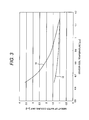
- FIG. 3 shows the weight of the water-cooling unit 8 when the ribs 9 for ventilation cooling are disposed in the water-cooling unit 8 (the weight being denoted by reference numeral 13) as well as the weight of the water-cooling unit 8 when the ribs 9 for ventilation cooling are not disposed (the weight being denoted by reference numeral 14).
- the temperature of the stator coil 7 is normalized by taking its upper temperature limit as 1, and the weight of the water-cooling unit 8 is similarly normalized by taking the weight of the water-cooling unit 8 without the ribs 9 as 1. Therefore, when the temperature of the stator coil 7 is 1 or below, the upper temperature limit is satisfied and the temperature is reduced; when the weight of the water-cooling unit 8 is 1 or more, the weight is increased.
- the ribs 9 are provided in the water-cooling unit 8, and air in the power generator is circulated by the axial fan 4, it becomes possible to lower the temperature of the stator coil 7 with the water-cooling unit 8. It is also possible to reduce the temperature due to heat exchange by the ribs 9 and to suppress the power generator weight.
- the water-cooling unit 8 As the structure of the cooling unit, the water-cooling unit 8, ribs 9, and power generator frame 10 are included as separate components in this embodiment. However, the water-cooling unit 8 and ribs 9 may be integrated together and the ribs 9 and power generator frame 10 may be integrated together.
- distributed winding is used as the method of winding the stator coil 7 around the stator 6, the number of poles is 12, and the number of stator slots 11 is 108.
- the same effect as in the example described above can be obtained from concentrated winding and another number of poles and slots.
- the permanent magnets 3 in the rotor 1 are flat-plate magnets and are disposed in V-shapes, it will be appreciated that other types of magnets may be disposed in another arrangement without any problem.
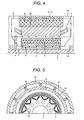
- FIGs. 4 and 5 show a permanent magnet power generator that is a second embodiment of the present invention.
- a plurality of axial ducts 15 for ventilation in the axial direction is formed in the rotor iron core 2 in the circumferential direction at equal intervals, between the shaft 5 and the permanent magnet 3 in the rotor 1.
- the axial fan 4 causes air in the power generator to flow between the rotor 1 and stator 6 and to flow in the axial ducts 15 in the axial direction, so ventilation resistance in the axial direction is reduced and the amount of air circulating in the interior can be increased. Since the bearing 16 is also exposed to the cooling air, the temperature of the bearing 16 can also be reduced.
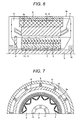
- FIGs. 6 and 7 Another structure by which the same effect as in the second embodiment can be obtained is shown in FIGs. 6 and 7 .
- a plurality of plates 17 extending in the axial direction is provided in the circumferential direction between the shaft 5 and rotor iron core 2, at equal intervals.
- the axial ducts 15 for ventilation in the axial direction are formed among the plates 17 disposed in the circumferential direction.
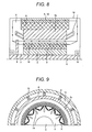
- FIGs. 8 and 9 Another structure by which the same effect as in the first embodiment can be obtained is shown in FIGs. 8 and 9 .
- the permanent magnets 3 are disposed in the circumferential direction in the rotor iron core 2 with their polarities alternately changed, and inter-pole ventilation paths 18 are formed by forming a groove between each two adjacent poles with different polarities, the groove extending in the axial direction and also extending in a radial direction from between the poles toward the center of the axis.
- the permanent magnets 3 in the rotor 1 are flat-plate magnets and are disposed in V-shapes in this embodiment, other types of magnets may be disposed in another arrangement without any problem.
- FIG. 10 shows a permanent magnet power generator that is a third embodiment of the present invention.
- the rotor 1 is formed of the rotor iron core 2, in which the permanent magnets 3 are embedded, and the rotor iron core 2 and two axial fans 4 are fixed at both ends of the shaft 5.
- a plurality of ducts 15 for ventilation in the axial direction is formed in the rotor iron core 2 in the circumferential direction at equal intervals.
- duct pieces 19 for ventilation cooling are provided in a radial pattern in radial directions at the center of the axial direction of the rotor iron core 2, at equal intervals in the circumferential direction therebetween. Radial ventilation paths are formed in the circumferential direction among the duct pieces 19.
- stator iron cores 2a are stacked in the axial direction and the stator coil 7 is provided.
- the stator 6 has duct pieces 19 for ventilation cooling, which are disposed in a radial pattern in radial directions at the center of the axial direction of the stator iron cores 2a, at predetermined intervals in the circumferential direction. Radial ventilation paths are formed in the circumferential direction among the duct pieces 19.
- the water-cooling unit 8 is disposed so as to come in contact with the outer circumference of the stator 6 and to be divided into two parts along the duct pieces 19 disposed at the center of the axial direction.
- ribs 9 for ventilation cooling are provided in the circumferential direction around the outer circumference of the water-cooling unit 8, at equal intervals.
- the power generator frame 10 is fixed around the outer circumference of the ribs 9 to seal the interior of the power generator.
- the axial fans 4 disposed at both ends of the shaft 5 enable the cooling air led between the rotor iron core 2 and stator iron cores 2a and led into the axial ducts 15 to form a plurality of flows circulating in both directions in the power generator through the radial ventilation paths formed in the duct pieces 19. Therefore, a temperature lowering effect by ventilation cooling can be expected.
- the temperature in the power generator is maximized near the center of the axial direction, when cooling air flows near the center of the axial direction, the maximum temperature can be reduced and the temperature distribution in the power generator can be equalized.
- the duct pieces 19 are disposed at the center of the axial direction in this embodiment, if an asymmetric structure in which the duct pieces 19 are displaced according to the place at which the temperature is maximized, the maximum temperature can be more efficiently lowered.
- the duct pieces 19 may also be disposed in a radial pattern in radial directions, at predetermined intervals in the axial direction.
- FIGs. 11 and 12 show a permanent magnet power generator that is a fourth embodiment of the present invention.
- a different number of ribs 9, which are disposed around the outer circumference of the water-cooling unit 8 in the first embodiment, are provided on each of the right and left sides of the center of the axial direction. That is, as shown in FIG. 12 , the number of ribs 9 on the side on which the axial fan 4 is fixed is smaller than the number of ribs 9 on the opposite side.
- the number of ribs 9 is larger on the side opposite to the axial fan 4, it is effective to provide more ribs 9 on a side on which temperature in the temperature distribution is high.
- FIG. 13 shows a permanent magnet power generator that is a fifth embodiment of the present invention.
- the maximum temperature can be lowered by providing the ribs 9 only near the center of the axial direction as in the fifth embodiment, and thereby the temperature distribution in the power generator can be equalized.
- FIG. 14 shows a permanent magnet power generator that is a sixth embodiment of the present invention.
- the axial fan 4 for flowing cooling air in the axial direction is disposed on one end of the shaft 5 as in the first embodiment, and a radial fan 4a for flowing cooling air in radial directions is provided on the opposite end of the shaft 5 with the rotor iron core 2 disposed therebetween.
- FIG. 15 shows a permanent magnet power generator that is a seventh embodiment of the present invention.
- the lengths of the coil ends 20 on the right and left of the stator coil shown in the first embodiment are not the same. That is, as shown in FIG. 15 , the axial length A of the coil end 20 on the side on which the axial fan 4 is disposed is longer than the axial length B of the coil end 20 on the side opposite to the axial fan 4.
- the coil end 20 on the side opposite to the axial fan 4 is shorter, the coil end 20 on the side on which the axial fan 4 is fixed may be shorter if the type of the fan or the like is changed.
- FIG. 16 shows internal flow paths, in three dimensions, in the water-cooling unit 8 shown in the first embodiment, as an eighth embodiment of the present invention.
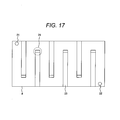
- FIG. 17 shows the internal flow paths in two dimensions.
- FIG. 16 cooling water flows from an inlet 21, circulates about one turn in the water-cooling unit 8, changes its flow direction by 180 degrees, and flows again about one turn. After repeating this cycle, the cooling water flows out of an exit 22.
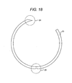
- FIG. 18 is a radial cross sectional view of a flow path wall 23 that forms one flow path in the water-cooling unit 8. The fluid flows along the circumferential direction and in the axial direction while changing its flow direction by 180 degrees at intermediate points. An oblique cut 24 is formed at an end of the flow path wall 23 at a corner where the fluid changes its flow direction (makes a U-turn).
- a notch 25 for drainage is made on the bottom (which faces the ground when the power generator is installed) of the flow path wall 23 in the drawing. Accordingly, since a drain outlet is formed on the ground side of the water-cooling unit 8, the cooling water flows through the notch 25. This prevents the cooling water from staying in the water-cooling unit 8, improving maintainability.
- a pump structured with a constant-speed machine or variable-speed machine is used as a unit for supplying cooling water to the water-cooling unit 8. If a pump structured with a variable-speed machine is used, the flow rate of the cooling water to be supplied to the water-cooling unit 8 can also be made variable. Therefore, the flow rate can be adjusted according to the output of the power generator, so the power consumption of the pump and other auxiliary machines can be suppressed and the efficiency of the entire system including the power generator can be improved.
- FIG. 19 shows flow paths, in two dimensions, in the water-cooling unit 8 shown in the first embodiment, as a ninth embodiment of the present invention.
- cooling water flows from the inlet 21 into the water-cooling unit 8, proceeds to an end in the axial direction of the water-cooling unit 8, and then changes its flow direction by 180 degrees.
- the cooling water travels in the circumferential direction while repeating this cycle, and flows out of the exit 22.
- Each flow path wall 23a has a bar shape different from the flow path wall 23 shown in the eighth embodiment, so the flow path wall 23a is highly machinable. If the oblique cut 24 is formed at an end of the flow path wall 23a at a corner where the fluid changes its flow direction (makes a U-turn), the same effect as with the structure in the eighth embodiment can be obtained.
- FIG. 20 shows a permanent magnet power generator that is a tenth embodiment of the present invention.
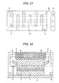
- FIG. 21 is a developed plan view of the water-cooling unit 8 with the pipes 26. As shown in the drawing, the pipes 26 for ventilation cooling are disposed so that they pass through the interior of the water-cooling unit 8 in the axial direction.
- FIG. 22 shows a permanent magnet power generator that is an eleventh embodiment of the present invention.
- the ribs 9 have been disposed around the outer circumference of the water-cooling unit 8 in the circumferential direction at equal intervals in the embodiments described so far, and the ventilation paths 12, through which cooling air flows, have been formed among the ribs 9.
- the ribs 9 may be eliminated and the pipes 26, through which cooling air directly flows, may be provided in the water-cooling unit 8.
- the cooling air that has cooled the interior of the machine and thereby has been heated is led into the pipes 26, where heat exchange with the water-cooling unit 8 is carried out to cool the heated cooling air.
- the cooled cooling air is circulated again in the power generator by the axial fan 4. Accordingly, the same effect as in the first embodiment described above can be obtained. Since the ribs 9 are eliminated, the number of parts can be reduced, improving the productivity.
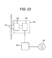
- FIG. 23 illustrates an example in which the power generator according to the present invention is applied to a wind power generating system.
- the power generator 100 described in the first to eleventh embodiments is connected to a windmill 101 through a speed-up gear 102 and mounted in a windmill nacelle 103.
- the power generator 100 is also connected to an electric power system 104 through a power converter 105 to generate electric power. It is also possible to directly interconnect the windmill 101 and power generator 100.
- wind is used as the power source
- a water mill, an engine, a turbine, or the like can be adequately applied, for example.
- the power generator for wind power generation in the above embodiment is advantageous in that even if the power generator has a large capacity, it can be cooled as a compact power generator.
Landscapes
- Engineering & Computer Science (AREA)
- Power Engineering (AREA)
- Motor Or Generator Cooling System (AREA)
- Connection Of Motors, Electrical Generators, Mechanical Devices, And The Like (AREA)
- Permanent Magnet Type Synchronous Machine (AREA)
Abstract
further comprising ventilation paths, through which the cooling air flows, formed around the outer circumference of the water-cooling unit;
wherein after the cooling air has been circulated by the fan in the machine for cooling, the cooling air is led to the ventilation paths to perform heat exchange between the cooling air flowing in the ventilation paths and the water-cooling unit, after which the cooling air is circulated again in the machine.
Description
- The present invention relates to a permanent magnet rotating electric machine and a wind power generating system, and more particularly to a permanent magnet rotating electric machine and a wind power generating system that are suitable to a permanent magnet power generator with a larger capacity of 1 MW or more.
- The use of electric power generated by wind has drastically increased in recent years. To improve economy by increasing the capacity of a single machine, there has been an increasing demand for permanent magnet rotating electric machines with a large capacity of 1 MW or more. When a large-capacity permanent magnet rotating electric machine is used, even if its efficiency is high, large loss is generated as an absolute value. To enable a large-capacity permanent magnet rotating electric machine to have a generated heat density equal to that of a small-capacity permanent magnet rotating electric machine, the body of the large-capacity permanent magnet rotating electric machine must be enlarged. When the body of the rotating electric machine is enlarged, however, its weight is increased and thereby manufacturing costs and construction costs are increased. Accordingly, it is necessary to increase the output density with a small body.
- However, an increase in output density causes an increase in generated heat density, so high cooling performance is required. As a result, an increase in cost is brought. If a permanent magnet rotating electric machine has a structure that does not easily generate heat, merits (a reduced body and high efficiency) gained by the use of permanent magnets are lessened, impairing electric characteristics. Then, it becomes difficult to satisfy specifications for electric power generators. To achieve highly efficient cooling at a low cost without impairing electric characteristics, a structure suitable for cooling is a requisite.
-
Patent Documents - That is,
Patent Document 1 discloses a structure in which a stator iron core has fins shaped like a star, in each of which a coolant flow path for cooling is formed.Patent Document 2 discloses a structure in which a heat-collecting jacket, in which a coolant flows around the outer circumference of a stator, is provided; and a heat dissipating jacket and a ventilation path are disposed outside the heat-collecting jacket. -
- Patent Document 1: Japanese Patent Laid-Open No.
2009-38864 - Patent Document 2: Japanese Patent Laid-Open No.
Hei 9(1997)-285071 - A wind power generator usually has a power generator structure including a rotor, a stator, and a heat exchanger used for cooling or a water-cooling unit. For a water-cooled power generator, heat generated by the power generator is cooled by a water-cooling unit in which cooling-water paths are formed. To reduce a temperature rise in the power generator, therefore, the body of the water-cooling unit itself must be enlarged. As a result, the body of the entire power generator and its weight are increased. For a permanent magnet power generator, heat is mainly generated by a stator coil, but when a water-cooling unit is disposed around the outer circumference of the stator, the coil temperature can be efficiently lowered. Accordingly, enlarging the body of a water-cooling unit is effective in lowering the temperature.
- In
Patent Document 1 described above, flow paths through which a coolant flows are formed in the iron stator. Since the stator iron is also used as a magnetic path through which a magnetic flux of a rotating magnetic field passes, the flow paths formed for a coolant flow increase magnetic resistance and lower the performance as a rotating machine. Furthermore, the flow paths, which are circumferentially and axially formed, are complex. When the motor is stopped for, for example, maintenance and the coolant is drained from the flow paths, some of the coolant may be left in the flow paths. - In
Patent Document 2, both a water-cooling structure and an air-cooling structure are used. Noting an air-cooling unit, the air-cooling unit has a structure in which an external fan disposed outside the rotating machine causes cooling air to flow. Although the structure is effective in lowering the stator coil temperature, however, the interior (rotor and bearing) is not sufficiently cooled. To reduce the temperature in the interior, the generated heat density in the interior must be lowered, resulting in a necessity for a large rotating machine body. - The present invention addresses the above problems with the object of providing a permanent magnet rotating electric machine that can efficiently reduce a temperature rise in the rotating machine without enlarging a heat exchanger and water-cooling unit.
- In a permanent magnet rotating electric machine according to the present invention that has a stator with a stator coil wound on a stator iron core, a rotor with a plurality of permanent magnets disposed in the circumferential direction in a rotor iron core, which is disposed opposite to the stator iron core of the stator with a predetermined spacing therebetween and is fixed to a shaft, a water-cooling unit disposed around the outer circumference of the stator iron core, and a fan fixed to the shaft on the same side as at least one axial end of the rotor iron core to circulate cooling air in the permanent magnet rotating electric machine, the present invention is characterized in that ventilation paths, through which the cooling air flows, are formed around the outer circumference of the water-cooling unit; after the cooling air has been circulated by the fan in the machine for cooling, the cooling air is led to the ventilation paths to perform heat exchange between the cooling air flowing in the ventilation paths and the water-cooling unit, after which the cooling air is circulated again in the machine.
- The present invention can provide a permanent magnet rotating electric machine that can efficiently reduce a temperature rise in the rotating machine without enlarging a heat exchanger and water-cooling unit and thereby can improve the cooling efficiency.
-
-
FIG. 1 is an axial cross sectional view showing a permanent magnet power generator that is a first embodiment of a permanent magnet rotating electric machine according to the present invention. (First embodiment) -
FIG. 2 is a radial cross sectional view ofFIG. 1 . -
-
FIG. 3 is a characteristic graph that represents, in the first embodiment, a relationship between the temperature of a stator coil and the weight of a water-cooling unit. (First embodiment) -
FIG. 4 is an axial cross sectional view showing a permanent magnet power generator that is a second embodiment of the permanent magnet rotating electric machine according to the present invention. (Second embodiment) -
FIG. 5 is a radial cross sectional view ofFIG. 4 . -
-
FIG. 6 is an axial cross sectional view showing another example of the permanent magnet power generator that is the second embodiment of the present invention. -
-
FIG. 7 is a radial cross sectional view ofFIG. 6 . -
-
FIG. 8 is an axial cross sectional view showing yet another example of the permanent magnet power generator that is the second embodiment of the present invention. -
-
FIG. 9 is a radial cross sectional view ofFIG. 8 . -
-
FIG. 10 is an axial cross sectional view showing a permanent magnet power generator that is a third embodiment of the permanent magnet rotating electric machine according to the present invention. (Third embodiment) -
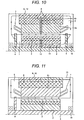
FIG. 11 is an axial cross sectional view showing a permanent magnet power generator that is a fourth embodiment of the permanent magnet rotating electric machine according to the present invention. (Fourth embodiment) -
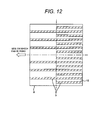
FIG. 12 is a plan view of the outer circumference of a water-cooling unit. (Fourth embodiment) -
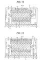
FIG. 13 is an axial cross sectional view showing a permanent magnet power generator that is a fifth embodiment of the permanent magnet rotating electric machine according to the present invention. (Fifth embodiment) -
FIG. 14 is an axial cross sectional view showing a permanent magnet power generator that is a sixth embodiment of the permanent magnet rotating electric machine according to the present invention. (Sixth embodiment) -
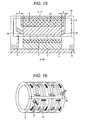
FIG. 15 is an axial cross sectional view showing a permanent magnet power generator that is a seventh embodiment of the permanent magnet rotating electric machine according to the present invention. (Seventh embodiment) -
FIG. 16 shows internal flow paths, in three dimensions, in a water-cooling unit in a permanent magnet power generator that is an eighth embodiment of the permanent magnet rotating electric machine according to the present invention. (Eighth embodiment) -
FIG. 17 shows the internal flow paths, in two dimensions, in the water-cooling unit shown inFIG. 16 . -
-
FIG. 18 is a radial cross sectional view of a flow path wall that forms one flow path in the water-cooling unit shown inFIG. 16 . (Eighth embodiment) -
FIG. 19 shows flow paths, in two dimensions, in a water-cooling unit in a permanent magnet power generator that is a ninth embodiment of the permanent magnet rotating electric machine according to the present invention. (Ninth embodiment) -
FIG. 20 is an axial cross sectional view showing a permanent magnet power generator that is a tenth embodiment of the permanent magnet rotating electric machine according to the present invention. (Tenth embodiment) -
FIG. 21 is a developed view of the water-cooling unit shown inFIG. 20 . (Tenth embodiment) -
FIG. 22 is an axial cross sectional view showing a permanent magnet power generator that is an eleventh embodiment of the permanent magnet rotating electric machine according to the present invention. (Eleventh embodiment) -
FIG. 23 shows a wind power generating system in which a permanent magnet power generator in the first to eleventh embodiments of the present invention is used. (Twelfth embodiment) - Permanent magnet power generators, which are permanent magnet rotating electric machines according to the present invention, will be described below in detail, with reference to the drawings. In the drawings, like elements are denoted by like reference numerals.
-
FIG. 1 shows a permanent magnet power generator that is a first embodiment of the present invention. - In
FIG. 1 , arotor 1 has arotor iron core 2, which is formed by laminating a plurality of electromagnetic steel plates in the axial direction; a plurality ofpermanent magnets 3 is embedded in the circumferential direction in the electromagnetic steel plates constituting therotor iron core 2, and therotor iron core 2 is fixed to ashaft 5. Anaxial fan 4, which circulates cooling air in the machine, is fixed to theshaft 5 at one end (on the left inFIG. 1 ) of therotor iron core 2 in the axial direction. Astator 6, which is disposed facing therotor 1 with a predetermined spacing therebetween, has astator iron core 2a formed by laminating a plurality of electromagnetic steel plates in the axial direction; astator coil 7 is provided in stator slots formed on the inner diameter side of thestator iron core 2a. A water-coolingunit 8, which is like a water-cooling jacket, is provided so as to come in contact with the outer circumferential surface of thestator 6.Ribs 9 for ventilation cooling are provided around the outer circumference of the water-coolingunit 8, at predetermined intervals in the circumferential direction. Apower generator frame 10 is fixed around the outer circumference of theribs 9 to seal the interior of the power generator.Reference numeral 16 indicates a bearing that rotatably supports theshaft 5. -
FIG. 2 is a radial cross sectional view ofFIG. 1 . Thepermanent magnets 3 embedded in therotor 1 as described above are disposed in the circumferential direction so as to form substantially "V" shapes while their polarities are alternately changed. Theribs 9 for ventilation cooling are disposed around the outer circumference of the water-coolingunit 8 at predetermined intervals in the circumferential direction; the circumferential intervals of theribs 9 are enclosed with thepower generator frame 10, which covers the entire power generator on the outer circumferential side of theribs 9, to formventilation paths 12. - The example shown in the drawing is a three-phase AC power generator in which the number of poles of the
rotor 1 is 12 and the number ofstator slots 11 is 108. - The flow of internal air will be described with reference to
FIGs. 1 and 2 . Theaxial fan 4 causes air in the power generator to flow in the axial direction between therotor 1 andstator 6. When the cooling air reaches the end in the axial direction, the cooling air changes its direction to a radial direction and cools the end of thestator coil 7. Then, the cooling air is led into theventilation paths 12 formed among theribs 9 disposed around the outer circumference of the water-coolingunit 8 and circulates in the power generator. That is, theribs 9 are equally spaced around the outer circumference of the water-coolingunit 8 in the circumferential direction as shown inFIG. 2 ; the cooling air circulates in the power generator while flowing in theventilation paths 12 formed among the disposedribs 9. - Accordingly, after the cooling air has been heated by being made to flow by the
axial fan 4 in the axial direction between therotor 1 andstator 6 and by cooling the end of thestator coil 7 and other parts, the cooling air is led to theventilation paths 12, so heat exchange occurs between the water-coolingunit 8 and the heated cooling air flowing through theventilation paths 12 and thereby the heated cooling air is cooled. The cooled cooling air is circulated again by theaxial fan 4 in the power generator. - Next, a relationship between the temperature of the
stator coil 7 and the weight of the water-cooling unit will be described with reference toFIG. 3. FIG. 3 shows the weight of the water-coolingunit 8 when theribs 9 for ventilation cooling are disposed in the water-cooling unit 8 (the weight being denoted by reference numeral 13) as well as the weight of the water-coolingunit 8 when theribs 9 for ventilation cooling are not disposed (the weight being denoted by reference numeral 14). - The temperature of the
stator coil 7 is normalized by taking its upper temperature limit as 1, and the weight of the water-coolingunit 8 is similarly normalized by taking the weight of the water-coolingunit 8 without theribs 9 as 1. Therefore, when the temperature of thestator coil 7 is 1 or below, the upper temperature limit is satisfied and the temperature is reduced; when the weight of the water-coolingunit 8 is 1 or more, the weight is increased. - It is found from the drawing that when the temperature of the
stator coil 7 is reduced, the weight of the water-coolingunit 8 tends to inherently increase. Noting the weight of the water-coolingunit 8 without theribs 9, which is denoted byreference numeral 14, it is found that as the temperature is lowered, the weight of the water-coolingunit 8 is greatly increased. Noting the weight of the water-coolingunit 8 with theribs 9, which is denoted byreference numeral 13, an increase in the weight of the water-coolingunit 8 is gradual in comparison withreference numeral 14 withoutribs 9. This indicates that as the number ofribs 9 is increased, the temperature can be lowered while an increase in the weight of the water-coolingunit 8 is suppressed. - Accordingly, when the water-cooling
unit 8 is mounted, theribs 9 are provided in the water-coolingunit 8, and air in the power generator is circulated by theaxial fan 4, it becomes possible to lower the temperature of thestator coil 7 with the water-coolingunit 8. It is also possible to reduce the temperature due to heat exchange by theribs 9 and to suppress the power generator weight. - As the structure of the cooling unit, the water-cooling
unit 8,ribs 9, andpower generator frame 10 are included as separate components in this embodiment. However, the water-coolingunit 8 andribs 9 may be integrated together and theribs 9 andpower generator frame 10 may be integrated together. - In this embodiment, distributed winding is used as the method of winding the
stator coil 7 around thestator 6, the number of poles is 12, and the number ofstator slots 11 is 108. However, the same effect as in the example described above can be obtained from concentrated winding and another number of poles and slots. Although thepermanent magnets 3 in therotor 1 are flat-plate magnets and are disposed in V-shapes, it will be appreciated that other types of magnets may be disposed in another arrangement without any problem. -
FIGs. 4 and 5 show a permanent magnet power generator that is a second embodiment of the present invention. - In the second embodiment shown in
FIGs. 4 and 5 , a plurality ofaxial ducts 15 for ventilation in the axial direction is formed in therotor iron core 2 in the circumferential direction at equal intervals, between theshaft 5 and thepermanent magnet 3 in therotor 1. - Accordingly, the
axial fan 4 causes air in the power generator to flow between therotor 1 andstator 6 and to flow in theaxial ducts 15 in the axial direction, so ventilation resistance in the axial direction is reduced and the amount of air circulating in the interior can be increased. Since thebearing 16 is also exposed to the cooling air, the temperature of thebearing 16 can also be reduced. - Another structure by which the same effect as in the second embodiment can be obtained is shown in
FIGs. 6 and 7 . As shown inFIGs, 6 and 7 , a plurality ofplates 17 extending in the axial direction is provided in the circumferential direction between theshaft 5 androtor iron core 2, at equal intervals. Theaxial ducts 15 for ventilation in the axial direction are formed among theplates 17 disposed in the circumferential direction. - In this structure, not only the same effect as in the embodiment described above can be obtained, but also costs can be reduced and rotor stiffness can be assured.
- Another structure by which the same effect as in the first embodiment can be obtained is shown in
FIGs. 8 and 9 . As shown inFIGs, 8 and 9 , thepermanent magnets 3 are disposed in the circumferential direction in therotor iron core 2 with their polarities alternately changed, andinter-pole ventilation paths 18 are formed by forming a groove between each two adjacent poles with different polarities, the groove extending in the axial direction and also extending in a radial direction from between the poles toward the center of the axis. - In this structure, not only the same effect as in the embodiment described above can be obtained, but also since the
inter-pole ventilation paths 18 are disposed close to thepermanent magnets 3, heat generated from thepermanent magnets 3 can be lessened by ventilation cooling through theinter-pole ventilation paths 18. - Although the
permanent magnets 3 in therotor 1 are flat-plate magnets and are disposed in V-shapes in this embodiment, other types of magnets may be disposed in another arrangement without any problem. -
FIG. 10 shows a permanent magnet power generator that is a third embodiment of the present invention. - In the permanent magnet power generator shown in the drawing, the
rotor 1 is formed of therotor iron core 2, in which thepermanent magnets 3 are embedded, and therotor iron core 2 and twoaxial fans 4 are fixed at both ends of theshaft 5. A plurality ofducts 15 for ventilation in the axial direction is formed in therotor iron core 2 in the circumferential direction at equal intervals. Furthermore,duct pieces 19 for ventilation cooling are provided in a radial pattern in radial directions at the center of the axial direction of therotor iron core 2, at equal intervals in the circumferential direction therebetween. Radial ventilation paths are formed in the circumferential direction among theduct pieces 19. - In the
stator 6,stator iron cores 2a are stacked in the axial direction and thestator coil 7 is provided. As with therotor 1, thestator 6 hasduct pieces 19 for ventilation cooling, which are disposed in a radial pattern in radial directions at the center of the axial direction of thestator iron cores 2a, at predetermined intervals in the circumferential direction. Radial ventilation paths are formed in the circumferential direction among theduct pieces 19. The water-coolingunit 8 is disposed so as to come in contact with the outer circumference of thestator 6 and to be divided into two parts along theduct pieces 19 disposed at the center of the axial direction. Furthermore,ribs 9 for ventilation cooling are provided in the circumferential direction around the outer circumference of the water-coolingunit 8, at equal intervals. Thepower generator frame 10 is fixed around the outer circumference of theribs 9 to seal the interior of the power generator. - In this structure, not only the same effect as in the embodiments described above can be obtained, but also the
axial fans 4 disposed at both ends of theshaft 5 enable the cooling air led between therotor iron core 2 andstator iron cores 2a and led into theaxial ducts 15 to form a plurality of flows circulating in both directions in the power generator through the radial ventilation paths formed in theduct pieces 19. Therefore, a temperature lowering effect by ventilation cooling can be expected. In addition, since the temperature in the power generator is maximized near the center of the axial direction, when cooling air flows near the center of the axial direction, the maximum temperature can be reduced and the temperature distribution in the power generator can be equalized. - Although the
duct pieces 19 are disposed at the center of the axial direction in this embodiment, if an asymmetric structure in which theduct pieces 19 are displaced according to the place at which the temperature is maximized, the maximum temperature can be more efficiently lowered. Theduct pieces 19 may also be disposed in a radial pattern in radial directions, at predetermined intervals in the axial direction. -
FIGs. 11 and12 show a permanent magnet power generator that is a fourth embodiment of the present invention. - In the fourth embodiment, a different number of
ribs 9, which are disposed around the outer circumference of the water-coolingunit 8 in the first embodiment, are provided on each of the right and left sides of the center of the axial direction. That is, as shown inFIG. 12 , the number ofribs 9 on the side on which theaxial fan 4 is fixed is smaller than the number ofribs 9 on the opposite side. - In this structure, not only the same effect as in the embodiments described above can be obtained, but also the number of
ribs 9 can be reduced. In addition, whenmore ribs 9 are provided on a side on which temperature is high with respect to a temperature distribution on the axial direction, the temperature distribution in the power generator can be equalized. - Although, in this embodiment, the number of
ribs 9 is larger on the side opposite to theaxial fan 4, it is effective to providemore ribs 9 on a side on which temperature in the temperature distribution is high. -
FIG. 13 shows a permanent magnet power generator that is a fifth embodiment of the present invention. - In the fifth embodiment, the
ribs 9, which are disposed around the outer circumference of the water-coolingunit 8 in the first embodiment, each have a shorter axial length than the water-coolingunit 8, and theribs 9 are disposed at the center of the axial direction. - In this structure, not only the same effect as in the embodiments described above can be obtained, but also although the temperature in the power generator tends to be maximized near the center in the axial direction, the maximum temperature can be lowered by providing the
ribs 9 only near the center of the axial direction as in the fifth embodiment, and thereby the temperature distribution in the power generator can be equalized. -
FIG. 14 shows a permanent magnet power generator that is a sixth embodiment of the present invention. - In the sixth embodiment, the
axial fan 4 for flowing cooling air in the axial direction is disposed on one end of theshaft 5 as in the first embodiment, and aradial fan 4a for flowing cooling air in radial directions is provided on the opposite end of theshaft 5 with therotor iron core 2 disposed therebetween. - This can not only provide the same effect as in the embodiments described above, but also reduce a temperature rise, because since the
axial fan 4 causes cooling air to flow in the axial direction and theradial fan 4a also causes cooling air to flow in the radial directions, the cooling air easily flows through theventilation paths 12 formed among theribs 9 and the amount of cooling air is increased. -
FIG. 15 shows a permanent magnet power generator that is a seventh embodiment of the present invention. - In the seventh embodiment, the lengths of the coil ends 20 on the right and left of the stator coil shown in the first embodiment are not the same. That is, as shown in
FIG. 15 , the axial length A of thecoil end 20 on the side on which theaxial fan 4 is disposed is longer than the axial length B of thecoil end 20 on the side opposite to theaxial fan 4. - In this structure, not only the same effect as in the embodiments described above can be obtained, but also since the axial length B of the
coil end 20 on the side opposite to theaxial fan 4 is shorter, ventilation resistance is reduced on the same side as thecoil end 20 with a shorter axial length and air easily flows on that side. Furthermore, since the lengths of the coil ends 20 on the right and left are not the same, the maximum temperature peak in the axial direction can be shifted toward a low temperature side. - Although, in this embodiment, the
coil end 20 on the side opposite to theaxial fan 4 is shorter, thecoil end 20 on the side on which theaxial fan 4 is fixed may be shorter if the type of the fan or the like is changed. -
FIG. 16 shows internal flow paths, in three dimensions, in the water-coolingunit 8 shown in the first embodiment, as an eighth embodiment of the present invention.FIG. 17 shows the internal flow paths in two dimensions. - As shown in
FIG. 16 , cooling water flows from aninlet 21, circulates about one turn in the water-coolingunit 8, changes its flow direction by 180 degrees, and flows again about one turn. After repeating this cycle, the cooling water flows out of anexit 22.FIG. 18 is a radial cross sectional view of aflow path wall 23 that forms one flow path in the water-coolingunit 8. The fluid flows along the circumferential direction and in the axial direction while changing its flow direction by 180 degrees at intermediate points. An oblique cut 24 is formed at an end of theflow path wall 23 at a corner where the fluid changes its flow direction (makes a U-turn). - In this structure, not only the same effect as in the embodiments described above can be obtained, but also bubbles and disturbance, which are caused by a difference in flow rate between the inside and outside of the corner where the fluid changes its flow direction, can be reduced and heat transfer can be equalized. Furthermore, a
notch 25 for drainage is made on the bottom (which faces the ground when the power generator is installed) of theflow path wall 23 in the drawing. Accordingly, since a drain outlet is formed on the ground side of the water-coolingunit 8, the cooling water flows through thenotch 25. This prevents the cooling water from staying in the water-coolingunit 8, improving maintainability. - A pump structured with a constant-speed machine or variable-speed machine is used as a unit for supplying cooling water to the water-cooling
unit 8. If a pump structured with a variable-speed machine is used, the flow rate of the cooling water to be supplied to the water-coolingunit 8 can also be made variable. Therefore, the flow rate can be adjusted according to the output of the power generator, so the power consumption of the pump and other auxiliary machines can be suppressed and the efficiency of the entire system including the power generator can be improved. -
FIG. 19 shows flow paths, in two dimensions, in the water-coolingunit 8 shown in the first embodiment, as a ninth embodiment of the present invention. - In the drawing, cooling water flows from the
inlet 21 into the water-coolingunit 8, proceeds to an end in the axial direction of the water-coolingunit 8, and then changes its flow direction by 180 degrees. The cooling water travels in the circumferential direction while repeating this cycle, and flows out of theexit 22. - In this structure, the cooling water flows in the axial direction while making U-turns, so the temperature distribution in the axial direction can be easily equalized. Each
flow path wall 23a has a bar shape different from theflow path wall 23 shown in the eighth embodiment, so theflow path wall 23a is highly machinable. If the oblique cut 24 is formed at an end of theflow path wall 23a at a corner where the fluid changes its flow direction (makes a U-turn), the same effect as with the structure in the eighth embodiment can be obtained. -
FIG. 20 shows a permanent magnet power generator that is a tenth embodiment of the present invention. - In the tenth embodiment,
pipes 26 for ventilation cooling are provided in the water-coolingunit 8 shown in the first embodiment.FIG. 21 is a developed plan view of the water-coolingunit 8 with thepipes 26. As shown in the drawing, thepipes 26 for ventilation cooling are disposed so that they pass through the interior of the water-coolingunit 8 in the axial direction. - In this structure, not only the same effect as in the embodiments described above can be obtained, but also since cooling air flows through the
ribs 9 and in the water-coolingunit 8, cooling efficiency is improved by water cooling and by heat exchange through thepipes 26. The structure shown in the third embodiment can also be used as the structure in the tenth embodiment. -
FIG. 22 shows a permanent magnet power generator that is an eleventh embodiment of the present invention. - The
ribs 9 have been disposed around the outer circumference of the water-coolingunit 8 in the circumferential direction at equal intervals in the embodiments described so far, and theventilation paths 12, through which cooling air flows, have been formed among theribs 9. In the eleventh embodiment shown inFIG. 22 , however, theribs 9 may be eliminated and thepipes 26, through which cooling air directly flows, may be provided in the water-coolingunit 8. - In this structure, the cooling air that has cooled the interior of the machine and thereby has been heated is led into the
pipes 26, where heat exchange with the water-coolingunit 8 is carried out to cool the heated cooling air. The cooled cooling air is circulated again in the power generator by theaxial fan 4. Accordingly, the same effect as in the first embodiment described above can be obtained. Since theribs 9 are eliminated, the number of parts can be reduced, improving the productivity. -
FIG. 23 illustrates an example in which the power generator according to the present invention is applied to a wind power generating system. - The
power generator 100 described in the first to eleventh embodiments is connected to awindmill 101 through a speed-up gear 102 and mounted in awindmill nacelle 103. Thepower generator 100 is also connected to anelectric power system 104 through apower converter 105 to generate electric power. It is also possible to directly interconnect thewindmill 101 andpower generator 100. - Although, in this embodiment, wind is used as the power source, a water mill, an engine, a turbine, or the like can be adequately applied, for example.
- The power generator for wind power generation in the above embodiment is advantageous in that even if the power generator has a large capacity, it can be cooled as a compact power generator.
Claims (17)
- A permanent magnet rotating electric machine that has a stator with a stator coil wound on a stator iron core, a rotor with a plurality of permanent magnets disposed in a circumferential direction in a rotor iron core, which is disposed opposite to the stator iron core of the stator with a predetermined spacing therebetween and is fixed to a shaft, a water-cooling unit disposed around an outer circumference of the stator iron core, and a fan fixed to the shaft on the same side as at least one axial end of the rotor iron core to circulate cooling air in the permanent magnet rotating electric machine, the machine being characterized in that a ventilation path, through which the cooling air flows, is formed around an outer circumference of the water-cooling unit; after the cooling air has been circulated by the fan in the machine for cooling, the cooling air is led to the ventilation path to perform heat exchange between the cooling air flowing in the ventilation path and the water-cooling unit, after which the cooling air is circulated again in the machine.
- The permanent magnet rotating electric machine according to claim 1, characterized in that a plurality of ribs is provided around an outer circumference of the water-cooling unit at predetermined intervals in a circumferential direction; a frame is provided around an outer circumference side of the ribs to cover the entire rotating electric machine to form; ventilation paths, through which the cooling air flows, are enclosed by the outer circumference of the water-cooling unit, the ribs, and the frame.
- The permanent magnet rotating electric machine according to claim 1 or 2, characterized in that a plurality of axial ducts for flowing the cooling air in an axial direction is formed in the rotor iron core in the circumferential direction at predetermined intervals.
- The permanent magnet rotating electric machine according to claim 1 or 2, characterized in that a plurality of plates extending in an axial direction is provided in the circumferential direction between the rotor iron core and the shaft, at predetermined intervals; axial ducts for flowing the cooling air in the axial direction are formed among the plurality of plates disposed in the circumferential direction.
- The permanent magnet rotating electric machine according to claim 1 or 2, characterized in that the permanent magnets are disposed in the circumferential direction in the rotor iron core with polarities thereof alternately changed; a ventilation path for flowing the cooling air is formed between each two adjacent poles with different polarities, the ventilation path extending in an axial direction and also extending in a radial direction from between the poles.
- The permanent magnet rotating electric machine according to claim 2, characterized in that a different number of ribs, which are disposed around the outer circumference of the water-cooling unit at predetermined intervals in the circumferential direction, are provided on each of both sides of a center of an axial direction.
- The permanent magnet rotating electric machine according to claim 6, characterized in that the number of ribs on a side on which the fan is fixed relative to the center of the axial direction is small.
- The permanent magnet rotating electric machine according to claim 2, characterized in that the plurality of ribs, which is disposed around the outer circumference of the water-cooling unit at predetermined intervals, each have a shorter axial length than the water-cooling unit, the ribs being disposed at a center of an axial direction.
- The permanent magnet rotating electric machine according to claim 2, characterized in that an axial fan for flowing cooling air in an axial direction and a radial fan for flowing cooling air in radial directions are provided as fans for circulating the cooling air in the permanent magnet rotating electric machine, the radial fan being disposed on the shaft at an end opposite to the axial fan with the rotor iron core disposed therebetween.
- The permanent magnet rotating electric machine according to claim 2, characterized in that axial lengths of coil ends on the right and left of the stator coil are not the same.
- The permanent magnet rotating electric machine according to claim 2, characterized in that a plurality of pipes through which cooling air flows is disposed so that the pipes pass through an interior of the water-cooling unit in an axial direction.
- The permanent magnet rotating electric machine according to claim 2, characterized in that the fans are fixed to the shaft at both axial ends of the rotor iron core; duct pieces extending in a radial pattern in radial directions are provided at at least a center of an axial direction of the stator and the rotor, at predetermined intervals in the circumferential direction; radial ventilation paths are formed circumferentially among the duct pieces; the water-cooling unit is divided at least along the duct pieces disposed at the center of the axial direction; after the cooling air has flowed through the ventilation paths, the cooling air is circulated in the machine in both directions by the fans, which are fixed to the shaft at both ends of the axial direction of the stator iron core, and is led to the axial ventilation paths; the cooling air that has led from the radial ventilation paths to the ventilation paths and cooling air that has undergone heat exchange with the water-cooling unit are circulated again in the machine in both directions.
- The permanent magnet rotating electric machine according to claim 12, characterized in that a plurality of axial ducts for flowing the cooling air in the axial direction is formed in the rotor iron core in the circumferential direction at predetermined intervals.
- The permanent magnet rotating electric machine according to claim 1, 2, or 11, characterized in that a flow path wall forms an internal flow path in the water-cooling unit, in which a coolant flows in the circumferential direction; a shape of the flow path wall at a corner where the coolant changes a flow direction thereof is such that a radial length in an outer diameter side is shorter than a radial length in an inner diameter side, the shape being oblique.
- The permanent magnet rotating electric machine according to claim 14, characterized in that the flow path wall forming the internal flow path in the water-cooling unit has a notch for drainage in a direction in which the rotating electric machines faces when the rotating electric machine is installed.
- The permanent magnet rotating electric machine according to claim 1, characterized in that the ventilation path is formed of a plurality of pipes.
- A wind power generating system in which a rotating electric machine mounted in a windmill nacelle is connected to a windmill through a speed-up gear, and the rotating electric machine is connected to an electric power system through a power converter, the system being characterized in that the rotating electric machine is the permanent magnet rotating electric machine described in any one of claims 1 to 16.
Applications Claiming Priority (1)
| Application Number | Priority Date | Filing Date | Title |
|---|---|---|---|
| JP2010076566A JP5260591B2 (en) | 2010-03-30 | 2010-03-30 | Permanent magnet rotating electrical machine and wind power generation system |
Publications (2)
| Publication Number | Publication Date |
|---|---|
| EP2372881A2 true EP2372881A2 (en) | 2011-10-05 |
| EP2372881A3 EP2372881A3 (en) | 2017-04-12 |
Family
ID=44310888
Family Applications (1)
| Application Number | Title | Priority Date | Filing Date |
|---|---|---|---|
| EP11000915.6A Withdrawn EP2372881A3 (en) | 2010-03-30 | 2011-02-04 | Permanent magnetic rotating electric machine and wind power generating system |
Country Status (4)
| Country | Link |
|---|---|
| US (1) | US8653703B2 (en) |
| EP (1) | EP2372881A3 (en) |
| JP (1) | JP5260591B2 (en) |
| CN (1) | CN102208845A (en) |
Cited By (16)
| Publication number | Priority date | Publication date | Assignee | Title |
|---|---|---|---|---|
| WO2012080566A1 (en) * | 2010-12-15 | 2012-06-21 | The Switch Drive Systems Oy | An electrical machine |
| CN102611248A (en) * | 2012-03-16 | 2012-07-25 | 赵晓东 | Permanent magnet synchronous motor cooled by two stages of heat exchangers |
| EP2602916A1 (en) * | 2011-12-06 | 2013-06-12 | Hamilton Sundstrand Space Systems International, Inc. | Cooling of permanent magnet electric machine |
| US8847444B2 (en) | 2010-11-12 | 2014-09-30 | Hamilton Sundstrand Space Systems International, Inc. | Cooling of permanent magnet electric machine |
| EP2852036A1 (en) * | 2013-09-16 | 2015-03-25 | ALSTOM Renewable Technologies | Electric machine with closed circuit air cooling |
| WO2015176703A1 (en) * | 2014-05-20 | 2015-11-26 | Schaeffler Technologies AG & Co. KG | Installation space optimized cooling jacket comprising a separator bar having a bracket for an electrical machine |
| EP3142231A1 (en) * | 2015-09-08 | 2017-03-15 | ABB Technology AG | An electric power generator |
| WO2018098567A1 (en) | 2016-11-29 | 2018-06-07 | Tm4 Inc. | Electric machine provided with an enclosed cooling assembly paired to an open cooling assembly |
| WO2018189023A1 (en) * | 2017-04-12 | 2018-10-18 | Wobben Properties Gmbh | Method for cooling a gearless wind turbine |
| WO2019020358A1 (en) * | 2017-07-24 | 2019-01-31 | Siemens Aktiengesellschaft | Electric motor and ship propulsion device |
| WO2019234771A1 (en) * | 2018-06-07 | 2019-12-12 | Mavel S.R.L. | Rotor for an electrical machine comprising air cooling elements an electrical machine comprising said rotor |
| CN110739803A (en) * | 2019-11-11 | 2020-01-31 | 东方电气集团东方电机有限公司 | Ventilation system for generator base |
| CN114320771A (en) * | 2021-12-02 | 2022-04-12 | 江苏海迪威液压有限公司 | Wind turbine converter water cooling system cooling state assessment early warning device |
| CN114844293A (en) * | 2022-06-14 | 2022-08-02 | 哈尔滨理工大学 | Variable-speed pumped-storage generator-motor with electric axial-centrifugal radial axial booster end ventilation system |
| US11952981B2 (en) | 2021-03-25 | 2024-04-09 | Wobben Properties Gmbh | Wind power installation and method for controlling a wind power installation |
| EP4266552A4 (en) * | 2020-12-21 | 2024-12-11 | LG Magna e-Powertrain Co., Ltd. | ENGINE ASSEMBLY |
Families Citing this family (44)
| Publication number | Priority date | Publication date | Assignee | Title |
|---|---|---|---|---|
| GB2485184B (en) * | 2010-11-04 | 2013-12-11 | Evo Electric Ltd | Axial flux electrical machines |
| PT2636131T (en) * | 2010-11-04 | 2020-04-24 | Wobben Properties Gmbh | WIND POWER INSTALLATION WITH SYNCHRONOUS GENERATOR AS WELL AS SLOW ROTATION SYNCHRONOUS GENERATOR |
| AT510446B1 (en) * | 2010-11-18 | 2012-04-15 | Avl List Gmbh | ELECTRICAL MACHINE |
| CN103187829A (en) * | 2011-12-30 | 2013-07-03 | 哈米尔顿森德斯特兰德空间系统国际有限公司 | Cooling of permanent magnet motor |
| CN102570670B (en) * | 2012-01-17 | 2014-06-04 | 东元总合科技(杭州)有限公司 | Rotor with internal spacers and motor employing rotor |
| WO2013171839A1 (en) * | 2012-05-15 | 2013-11-21 | 株式会社安川電機 | Dynamo-electric machine |
| DE102012208549A1 (en) * | 2012-05-22 | 2013-11-28 | Wobben Properties Gmbh | Optimized synchronous generator of a gearless wind turbine |
| GB2506970B (en) * | 2012-08-24 | 2020-12-30 | Borgwarner Inc | A shield and coolant guide for an electric machine |
| US20140084721A1 (en) * | 2012-09-25 | 2014-03-27 | Debabrata Pal | Motor assembly cooling arrangement and method of cooling a motor assembly |
| JP5547783B2 (en) * | 2012-09-27 | 2014-07-16 | 株式会社小松製作所 | Electric motor and its cooling water circuit |
| US9058955B2 (en) | 2012-12-06 | 2015-06-16 | GE Lighting Solutions, LLC | Lamp comprising active cooling device for thermal management |
| JP6063288B2 (en) * | 2013-02-15 | 2017-01-18 | 住友重機械工業株式会社 | Power transmission device |
| CN104079119A (en) * | 2013-03-26 | 2014-10-01 | 德昌电机(深圳)有限公司 | Motor assembly and household appliance comprising motor assembly |
| NO335892B1 (en) * | 2013-04-10 | 2015-03-16 | Smartmotor As | Underwater electromechanical energy converter |
| JP2014220901A (en) * | 2013-05-08 | 2014-11-20 | 三菱電機株式会社 | Permanent magnet built-in type rotary electric machine |
| JP6169496B2 (en) * | 2014-01-09 | 2017-07-26 | 株式会社日立製作所 | Permanent magnet rotating electric machine |
| CN104167841A (en) * | 2014-08-26 | 2014-11-26 | 冯军 | Electric generator |
| DE102014220847A1 (en) * | 2014-10-15 | 2016-04-21 | Würth Elektronik eiSos Gmbh & Co. KG | communicator |
| EP3046225A1 (en) * | 2015-01-16 | 2016-07-20 | Siemens Aktiengesellschaft | Electric rotary machine having one-sided cooling, and method for one-sided cooling |
| CN104810997B (en) * | 2015-04-15 | 2017-03-01 | 新疆金风科技股份有限公司 | Permanent magnet direct-driving aerogenerator system and its collaborative drying control method of sealing |
| CN104953766B (en) * | 2015-06-17 | 2018-11-13 | 北京金风科创风电设备有限公司 | Radial ventilation cooling structure of motor |
| CN105245046A (en) * | 2015-10-26 | 2016-01-13 | 王石柱 | High speed motor rotor structure and processing technology |
| JP2017192163A (en) * | 2016-04-11 | 2017-10-19 | 東芝三菱電機産業システム株式会社 | Totally-enclosed dynamo-electric machine |
| CN106849509B (en) * | 2017-04-25 | 2023-06-06 | 沈阳工程学院 | Hollow rotor cooling structure of ultra-high-speed permanent magnet motor |
| CN107370292A (en) * | 2017-07-31 | 2017-11-21 | 中车唐山机车车辆有限公司 | The cooling device of magneto |
| US10256688B1 (en) | 2017-10-10 | 2019-04-09 | Zero E Technologies, Llc | Electric machine rotor cooling systems and methods |
| CN109888954B (en) * | 2017-12-06 | 2025-07-04 | 苏州保邦电气有限公司 | Centrifugal magnetic steel cooling structure of magnetic levitation high-speed permanent magnet motor |
| CN109888976A (en) * | 2017-12-06 | 2019-06-14 | 苏州保邦电气有限公司 | The vane type heat dissipation shaft of magnetic-suspension high-speed magneto |
| CN109888975A (en) * | 2017-12-06 | 2019-06-14 | 苏州保邦电气有限公司 | The vane type magnet steel cooling structure of magnetic-suspension high-speed magneto |
| TWI652884B (en) * | 2017-12-20 | 2019-03-01 | 東元電機股份有限公司 | Motor frame with bumps |
| JP6624223B2 (en) | 2018-03-09 | 2019-12-25 | 株式会社明電舎 | Rotating electric machine |
| CN109474092B (en) * | 2019-01-14 | 2025-02-25 | 上海盘毂动力科技股份有限公司 | A stator assembly and axial magnetic field motor |
| CN111490635A (en) * | 2019-01-29 | 2020-08-04 | 青岛海尔智能技术研发有限公司 | Motor cooling system of centrifugal refrigeration compressor and centrifugal refrigeration compressor |
| JP2020129891A (en) * | 2019-02-08 | 2020-08-27 | 株式会社日立インダストリアルプロダクツ | Rotary electric machine and hoist system using the same for elevator |
| US12062970B2 (en) * | 2020-02-21 | 2024-08-13 | Mitsubishi Electric Corporation | Electric motor |
| CN112421885A (en) * | 2020-11-10 | 2021-02-26 | 国家电网有限公司 | Closed-circuit self-circulation ventilation cooling system of hydro-generator |
| CN112636501B (en) * | 2020-11-27 | 2022-04-08 | 联合汽车电子有限公司 | Motor rotor and motor |
| DE102020216230A1 (en) * | 2020-12-18 | 2022-06-23 | Zf Friedrichshafen Ag | Electrical machine for driving a motor vehicle |
| CN112803635B (en) * | 2021-03-22 | 2021-06-29 | 沈阳工业大学 | Cooling system structure of permanent magnet motor |
| US11863051B2 (en) | 2021-05-13 | 2024-01-02 | General Electric Company | Thermal management system |
| US11942826B2 (en) * | 2021-09-24 | 2024-03-26 | Rolls-Royce Electrical Norway AS | Electric machine cooling |
| CN114844292B (en) * | 2022-06-14 | 2025-09-12 | 哈尔滨理工大学 | Low-speed permanent magnet motor with oil-cooled stator core and axial ventilation cooling system |
| CN116014979B (en) * | 2023-01-06 | 2025-07-04 | 江苏大中电机股份有限公司 | A composite cooling system for permanent magnet motor |
| CN118088400A (en) * | 2024-04-09 | 2024-05-28 | 新疆新风新能环保科技有限公司 | A water cooling circulation device for a wind turbine generator set |
Citations (1)
| Publication number | Priority date | Publication date | Assignee | Title |
|---|---|---|---|---|
| JP2009038864A (en) | 2007-07-31 | 2009-02-19 | Nissan Motor Co Ltd | Motor cooling device and cooling method thereof. |
Family Cites Families (23)
| Publication number | Priority date | Publication date | Assignee | Title |
|---|---|---|---|---|
| US2505795A (en) * | 1946-11-13 | 1950-05-02 | Ohio Crankshaft Co | Cooling power unit |
| DE1802282U (en) * | 1958-10-01 | 1959-12-17 | Licentia Gmbh | COOLING ARRANGEMENT FOR CLOSED ELECTRIC MACHINERY WITH COOLED STAND HOUSING. |
| DE1763579A1 (en) * | 1968-06-26 | 1971-11-11 | Siemens Ag | Arrangement for liquid cooling of the stator core assemblies of electrical machines, especially for turbo generators |
| US3784851A (en) * | 1971-03-03 | 1974-01-08 | Fuji Electric Co Ltd | Ventillating arrangement for dynamo-electric machines |
| JPS57202855A (en) * | 1982-05-13 | 1982-12-11 | Toshiba Corp | Air cooler for rotary electric machine |
| IT209469Z2 (en) * | 1985-07-09 | 1988-10-10 | Lafert Srl | FORCED ELECTRIC MOTOR FORCED WITH LIQUID. |
| JPH09149599A (en) * | 1995-11-27 | 1997-06-06 | Hitachi Ltd | Fully closed rotating electric machine |
| JPH09285071A (en) | 1996-04-19 | 1997-10-31 | Fuji Electric Co Ltd | Refrigerant cooling rotary electric machine |
| CN2271771Y (en) * | 1996-07-02 | 1997-12-31 | 施振山 | Motor housing with flow-guided cooling paths |
| JP3205897B2 (en) * | 1996-07-12 | 2001-09-04 | 株式会社滋賀山下 | Hammering equipment for casting sand removal |
| JPH10290551A (en) * | 1997-04-15 | 1998-10-27 | Matsushita Electric Works Ltd | Motor |
| JP2000116060A (en) * | 1998-09-29 | 2000-04-21 | Nishishiba Electric Co Ltd | Rotating electric machine |
| DE19905540A1 (en) * | 1999-02-10 | 2000-08-17 | Zahnradfabrik Friedrichshafen | Electrical machine |
| JP2001238395A (en) * | 2000-02-25 | 2001-08-31 | Hitachi Ltd | Fully closed motor with cooling ribs |
| US6737768B2 (en) * | 2000-03-31 | 2004-05-18 | Hitachi, Ltd. | Rotating electric machine |
| US7019413B2 (en) * | 2000-05-19 | 2006-03-28 | Yukio Kinoshita | System having an electric device which functions both as an electric motor for driving machines and as a generator to generate electrical power, and having a power source for driving the electric device |
| JP2005039926A (en) * | 2003-07-14 | 2005-02-10 | Kawasaki Heavy Ind Ltd | Low speed electric motor |
| JP4572647B2 (en) * | 2004-10-01 | 2010-11-04 | 株式会社日立製作所 | Permanent magnet rotating electrical machine and wind power generation system |
| JP2006197785A (en) * | 2004-12-14 | 2006-07-27 | Nissan Motor Co Ltd | Motor cooling device |
| JP4800847B2 (en) * | 2006-06-01 | 2011-10-26 | 三菱電機株式会社 | Fully closed liquid-cooled electric motor |
| DE102006043169B4 (en) * | 2006-09-14 | 2008-10-16 | Siemens Ag | Electric machine with an internally cooled rotor |
| JP5157138B2 (en) | 2006-11-24 | 2013-03-06 | 株式会社日立製作所 | Permanent magnet rotating electrical machine and wind power generation system |
| CN201142605Y (en) * | 2008-01-15 | 2008-10-29 | 江苏远东电机制造有限公司 | Ventilation structure between motor base and stator |
-
2010
- 2010-03-30 JP JP2010076566A patent/JP5260591B2/en active Active
-
2011
- 2011-02-04 EP EP11000915.6A patent/EP2372881A3/en not_active Withdrawn
- 2011-02-17 CN CN2011100409861A patent/CN102208845A/en active Pending
- 2011-02-17 US US13/029,287 patent/US8653703B2/en not_active Expired - Fee Related
Patent Citations (1)
| Publication number | Priority date | Publication date | Assignee | Title |
|---|---|---|---|---|
| JP2009038864A (en) | 2007-07-31 | 2009-02-19 | Nissan Motor Co Ltd | Motor cooling device and cooling method thereof. |
Cited By (20)
| Publication number | Priority date | Publication date | Assignee | Title |
|---|---|---|---|---|
| US8847444B2 (en) | 2010-11-12 | 2014-09-30 | Hamilton Sundstrand Space Systems International, Inc. | Cooling of permanent magnet electric machine |
| WO2012080566A1 (en) * | 2010-12-15 | 2012-06-21 | The Switch Drive Systems Oy | An electrical machine |
| EP2602916A1 (en) * | 2011-12-06 | 2013-06-12 | Hamilton Sundstrand Space Systems International, Inc. | Cooling of permanent magnet electric machine |
| CN102611248A (en) * | 2012-03-16 | 2012-07-25 | 赵晓东 | Permanent magnet synchronous motor cooled by two stages of heat exchangers |
| EP2852036A1 (en) * | 2013-09-16 | 2015-03-25 | ALSTOM Renewable Technologies | Electric machine with closed circuit air cooling |
| WO2015176703A1 (en) * | 2014-05-20 | 2015-11-26 | Schaeffler Technologies AG & Co. KG | Installation space optimized cooling jacket comprising a separator bar having a bracket for an electrical machine |
| EP3142231A1 (en) * | 2015-09-08 | 2017-03-15 | ABB Technology AG | An electric power generator |
| WO2018098567A1 (en) | 2016-11-29 | 2018-06-07 | Tm4 Inc. | Electric machine provided with an enclosed cooling assembly paired to an open cooling assembly |
| US11218057B2 (en) | 2016-11-29 | 2022-01-04 | Dana Tm4 Inc. | Electric machine provided with an enclosed cooling assembly paired to an open cooling assembly |
| EP3549242A4 (en) * | 2016-11-29 | 2020-07-08 | TM4 Inc. | ELECTRIC MACHINE WITH A CLOSED COOLING UNIT COUPLED TO AN OPEN COOLING UNIT |
| WO2018189023A1 (en) * | 2017-04-12 | 2018-10-18 | Wobben Properties Gmbh | Method for cooling a gearless wind turbine |
| US10961986B2 (en) | 2017-04-12 | 2021-03-30 | Wobben Properties Gmbh | Method for cooling a gearless wind turbine |
| WO2019020358A1 (en) * | 2017-07-24 | 2019-01-31 | Siemens Aktiengesellschaft | Electric motor and ship propulsion device |
| WO2019234771A1 (en) * | 2018-06-07 | 2019-12-12 | Mavel S.R.L. | Rotor for an electrical machine comprising air cooling elements an electrical machine comprising said rotor |
| CN110739803A (en) * | 2019-11-11 | 2020-01-31 | 东方电气集团东方电机有限公司 | Ventilation system for generator base |
| EP4266552A4 (en) * | 2020-12-21 | 2024-12-11 | LG Magna e-Powertrain Co., Ltd. | ENGINE ASSEMBLY |
| US12562615B2 (en) | 2020-12-21 | 2026-02-24 | Lg Electronics Inc. | Motor assembly |
| US11952981B2 (en) | 2021-03-25 | 2024-04-09 | Wobben Properties Gmbh | Wind power installation and method for controlling a wind power installation |
| CN114320771A (en) * | 2021-12-02 | 2022-04-12 | 江苏海迪威液压有限公司 | Wind turbine converter water cooling system cooling state assessment early warning device |
| CN114844293A (en) * | 2022-06-14 | 2022-08-02 | 哈尔滨理工大学 | Variable-speed pumped-storage generator-motor with electric axial-centrifugal radial axial booster end ventilation system |
Also Published As
| Publication number | Publication date |
|---|---|
| JP5260591B2 (en) | 2013-08-14 |
| EP2372881A3 (en) | 2017-04-12 |
| US20110241350A1 (en) | 2011-10-06 |
| JP2011211816A (en) | 2011-10-20 |
| US8653703B2 (en) | 2014-02-18 |
| CN102208845A (en) | 2011-10-05 |
Similar Documents
| Publication | Publication Date | Title |
|---|---|---|
| US8653703B2 (en) | Permanent magnetic rotating electric machine and wind power generating system | |
| JP5358667B2 (en) | Permanent magnet generator | |
| US7994668B2 (en) | Cooling system for rotating machine | |
| CA2656986C (en) | Process and devices for cooling an electric machine | |
| US7847456B2 (en) | Permanent magnet electrical rotating machine, wind power generating system, and a method of magnetizing a permanent magnet | |
| US8648505B2 (en) | Electrical machine with multiple cooling flows and cooling method | |
| CA2683462C (en) | Arrangement for cooling of an electrical machine | |
| US8350434B2 (en) | Permanent magnet type rotary electric machine | |
| US11973398B2 (en) | Electric motor cooling system and method for operation of said system | |
| CA2683455C (en) | Arrangement for cooling of an electrical machine | |
| CN102290922A (en) | Double-fed wind generator | |
| KR102927962B1 (en) | Cooling of electrical machines | |
| KR101276065B1 (en) | Cooling system of water jacket style generator | |
| JP4561408B2 (en) | Rotating electric machine | |
| CN118214202A (en) | Axial partition ventilation hydraulic generator suitable for high speed and large capacity | |
| CN108667218B (en) | Brushless doubly-fed motor self-driven cooling structure based on cooling liquid | |
| EP2950430B1 (en) | Electrical machine system and wind power generating system | |
| JP2013158161A (en) | Rotary electric machine | |
| WO2022086459A1 (en) | A liquid - cooled cooling method for electric motors and alternators | |
| CN208797768U (en) | A kind of brushless dual-feed motor cooling structure based on coolant liquid | |
| JP2015198512A (en) | Permanent magnet type dynamo-electric machine |
Legal Events
| Date | Code | Title | Description |
|---|---|---|---|
| PUAI | Public reference made under article 153(3) epc to a published international application that has entered the european phase |
Free format text: ORIGINAL CODE: 0009012 |
|
| 17P | Request for examination filed |
Effective date: 20110607 |
|
| AK | Designated contracting states |
Kind code of ref document: A2 Designated state(s): AL AT BE BG CH CY CZ DE DK EE ES FI FR GB GR HR HU IE IS IT LI LT LU LV MC MK MT NL NO PL PT RO RS SE SI SK SM TR |
|
| AX | Request for extension of the european patent |
Extension state: BA ME |
|
| PUAL | Search report despatched |
Free format text: ORIGINAL CODE: 0009013 |
|
| AK | Designated contracting states |
Kind code of ref document: A3 Designated state(s): AL AT BE BG CH CY CZ DE DK EE ES FI FR GB GR HR HU IE IS IT LI LT LU LV MC MK MT NL NO PL PT RO RS SE SI SK SM TR |
|
| AX | Request for extension of the european patent |
Extension state: BA ME |
|
| RIC1 | Information provided on ipc code assigned before grant |
Ipc: H02K 9/06 20060101AFI20170308BHEP Ipc: H02K 1/20 20060101ALI20170308BHEP Ipc: H02K 9/08 20060101ALI20170308BHEP |
|
| STAA | Information on the status of an ep patent application or granted ep patent |
Free format text: STATUS: REQUEST FOR EXAMINATION WAS MADE |
|
| STAA | Information on the status of an ep patent application or granted ep patent |
Free format text: STATUS: THE APPLICATION IS DEEMED TO BE WITHDRAWN |
|
| 18D | Application deemed to be withdrawn |
Effective date: 20171013 |