EP2372407A2 - Élément optique avec une lentille de Fresnel, appareil d'affichage, procédé d'affichage et corps en mouvement - Google Patents
Élément optique avec une lentille de Fresnel, appareil d'affichage, procédé d'affichage et corps en mouvement Download PDFInfo
- Publication number
- EP2372407A2 EP2372407A2 EP11153328A EP11153328A EP2372407A2 EP 2372407 A2 EP2372407 A2 EP 2372407A2 EP 11153328 A EP11153328 A EP 11153328A EP 11153328 A EP11153328 A EP 11153328A EP 2372407 A2 EP2372407 A2 EP 2372407A2
- Authority
- EP
- European Patent Office
- Prior art keywords
- major surface
- optical element
- optical
- fresnel lens
- ridge portions
- Prior art date
- Legal status (The legal status is an assumption and is not a legal conclusion. Google has not performed a legal analysis and makes no representation as to the accuracy of the status listed.)
- Withdrawn
Links
Images


Classifications
-
- G—PHYSICS
- G02—OPTICS
- G02B—OPTICAL ELEMENTS, SYSTEMS OR APPARATUS
- G02B3/00—Simple or compound lenses
- G02B3/02—Simple or compound lenses with non-spherical faces
- G02B3/08—Simple or compound lenses with non-spherical faces with discontinuous faces, e.g. Fresnel lens
-
- G—PHYSICS
- G02—OPTICS
- G02B—OPTICAL ELEMENTS, SYSTEMS OR APPARATUS
- G02B5/00—Optical elements other than lenses
- G02B5/08—Mirrors
-
- B—PERFORMING OPERATIONS; TRANSPORTING
- B60—VEHICLES IN GENERAL
- B60R—VEHICLES, VEHICLE FITTINGS, OR VEHICLE PARTS, NOT OTHERWISE PROVIDED FOR
- B60R1/00—Optical viewing arrangements; Real-time viewing arrangements for drivers or passengers using optical image capturing systems, e.g. cameras or video systems specially adapted for use in or on vehicles
- B60R1/001—Optical viewing arrangements; Real-time viewing arrangements for drivers or passengers using optical image capturing systems, e.g. cameras or video systems specially adapted for use in or on vehicles integrated in the windows, e.g. Fresnel lenses
-
- G—PHYSICS
- G02—OPTICS
- G02B—OPTICAL ELEMENTS, SYSTEMS OR APPARATUS
- G02B27/00—Optical systems or apparatus not provided for by any of the groups G02B1/00 - G02B26/00, G02B30/00
- G02B27/0018—Optical systems or apparatus not provided for by any of the groups G02B1/00 - G02B26/00, G02B30/00 with means for preventing ghost images
-
- G—PHYSICS
- G02—OPTICS
- G02B—OPTICAL ELEMENTS, SYSTEMS OR APPARATUS
- G02B27/00—Optical systems or apparatus not provided for by any of the groups G02B1/00 - G02B26/00, G02B30/00
- G02B27/01—Head-up displays
-
- G—PHYSICS
- G02—OPTICS
- G02B—OPTICAL ELEMENTS, SYSTEMS OR APPARATUS
- G02B27/00—Optical systems or apparatus not provided for by any of the groups G02B1/00 - G02B26/00, G02B30/00
- G02B27/01—Head-up displays
- G02B27/0101—Head-up displays characterised by optical features
-
- G—PHYSICS
- G02—OPTICS
- G02B—OPTICAL ELEMENTS, SYSTEMS OR APPARATUS
- G02B27/00—Optical systems or apparatus not provided for by any of the groups G02B1/00 - G02B26/00, G02B30/00
- G02B27/01—Head-up displays
- G02B27/0149—Head-up displays characterised by mechanical features
- G02B2027/015—Head-up displays characterised by mechanical features involving arrangement aiming to get less bulky devices
Definitions
- Embodiments described herein relate generally to an optical element, a display apparatus, a display method, and a moving body.
- Head-up displays that allow an operator to view image information and an image of the scenery of the external environment by displaying various image information on a windshield of a moving body such as a vehicle, aircraft, etc.
- HUDs Head-up displays
- JP-A 11-271665 Korean Patent Application Laidity (1999 ) discusses technology regarding a head-up display that uses a liquid crystal display device.
- an optical element in general, includes a first optical sheet having a first major surface.
- the first optical sheet includes a first Fresnel lens provided in the first major surface.
- An optical axis of the first Fresnel lens at the first major surface is disposed at a position different from a position of a center of an outline of the first major surface.
- a first embodiment of the invention is an optical element used in a display apparatus such as a HUD.
- the display apparatus can be used as a HUD mounted in moving bodies such as vehicles, ships, aircraft, etc.
- the embodiments of the invention are not limited thereto.
- the display apparatus may be applied in simulators such as driving simulators, flight simulators, etc., and in amusement applications such as games.
- the optical element according to this embodiment is applied in a display apparatus of a HUD for a vehicle is described as an example.
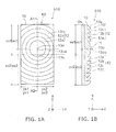
- FIGS. 1A and 1B are schematic views illustrating the configuration of the optical element according to the first embodiment of the invention.
- FIG. 1A is a plan view
- FIG. 1B is a cross-sectional view along line A1-A2 of FIG. 1A .
- FIG. 2 is a schematic view illustrating a state of use of a display apparatus in which the optical element according to the first embodiment of the invention is used.
- the display apparatus 310 is mounted in a vehicle 730 (a moving body).
- the display apparatus 310 includes an image projection unit 115.
- the display apparatus 310 also may include an image data generation unit 130.
- the image data generation unit 130 generates image data.
- the image projection unit 115 projects a light flux 112 including an image based on the image data generated by the image data generation unit 130 toward a human viewer 100 riding in the vehicle 730 by using a windshield unit 710 of the vehicle 730 to reflect the light flux 112.
- the windshield unit 710 includes a windshield 710a of the vehicle 730.
- the windshield unit 710 includes, for example, a reflecting unit 711 provided in the windshield 710a of the vehicle 730.
- An optical element 510 may be used as the reflecting unit 711.
- the optical element 510 may be adhered to, for example, the indoor side of the windshield 710a.
- the optical element 510 may be built into the windshield 710a.
- the optical element 510 may be disposed proximally to the windshield 710a on the indoor side of the windshield 710a apart from the windshield 710a.
- a member supporting the optical element 510 also may be included in the windshield unit 710.
- the image included in the light flux 112 may include, for example, various content regarding the operation information of the vehicle 730 in which the display apparatus 310 is mounted such as "arrows" indicating the travel direction, the speed, etc.
- the image projection unit 115 of the display apparatus 310 may be provided, for example, inside the vehicle 730, that is, for example, in an inner portion of a dashboard 720 of the vehicle 730 as viewed by the human viewer 100, i.e., an operator.
- the light flux 112 emitted from the image projection unit 115 is reflected by the windshield unit 710 and is incident on a head 105 of the human viewer 100. Specifically, the light flux 112 reaches an eye 101 of the human viewer 100.
- the human viewer 100 perceives an image 181 (a virtual image) of display content 180 included in the image formed at the position of an image formation position 181p via the windshield unit 710.
- the display apparatus 310 can be used as a HUD.
- the display apparatus 310 includes the image projection unit 115 that projects a light flux including an image toward the human viewer 100 by using the optical element 510 according to this embodiment of the invention to reflect the light flux.
- the display apparatus may further include the optical element 510.
- the optical element 510 includes a first optical sheet 10 including a first Fresnel lens 10f provided in a first major surface 10a.
- An optical axis 13oa of the first Fresnel lens 10f is disposed at a position in the first major surface 10a different from the position of the center of the outline of the first major surface 10a (an outline center 13s).
- the first Fresnel lens 10f is a convex Fresnel lens.
- the first Fresnel lens 10f may be a concave Fresnel lens.
- the case is described where the first Fresnel lens 10f is a convex Fresnel lens.
- a protrusion 11 having a convex curved surface is provided in the first major surface 10a; and multiple ridge portions 12 (e.g., a ridge portion 12a, a ridge portion 12b, a ridge portion 12c, a ridge portion 12d, etc., from a center 13o of the concentric circles toward the outside) having curved surfaces are provided in the first major surface 10a in concentric circular configurations around the protrusion 11. Thereby, the first Fresnel lens 10f is formed.
- the thickness of the portion of each of the ridge portions 12 on the side proximal to the center 13o is greater than the thickness of the portion on the side distal to the center 13o.
- the outline of the first major surface 10a (i.e., the outline of the optical element 510 as viewed from a direction perpendicular to the first major surface 10a) is, for example, rectangular. This embodiment is not limited thereto.
- the outline of the first major surface 10a may be circular, flattened circular, or rectangular with round corners.
- a distance ys1 along the Y-axis direction from one end of the outline of the first major surface 10a along the Y-axis direction to the outline center 13s is equal to a distance ys2 along the Y-axis direction from one other end of the outline of the first major surface 10a along the Y-axis direction to the outline center 13s.
- the optical axis 13oa of the first Fresnel lens 10f of the first major surface 10a is the center of the protrusion 11 and is the center 13o of the concentric circles of the multiple ridge portions 12.
- the optical axis 13oa of the first Fresnel lens 10f is disposed at a position different from the position of the outline center 13s.
- a distance xo1 along the X-axis direction from one end of the outline of the first major surface 10a along the X-axis direction to the optical axis 13oa is different from a distance xo2 along the X-axis direction from one other end of the outline of the first major surface 10a along the X-axis direction to the optical axis 13oa.
- the optical axis 13oa is disposed at a position different from the position of the outline center 13s along the X-axis direction.
- the first major surface 10a of the optical element 510 is capable of reflecting and transmitting visible light.
- the optical element 510 can be applied in a HUD by, for example, being adhered on the inner side of the windshield 710a of the vehicle 730 with the first major surface 10a side opposing the windshield 710a.
- the optical element 510 can reflect the light flux 112 emitted from the image projection unit 115 of the display apparatus 310 toward the human viewer 100, transmit light of the scenery of the external environment of the vehicle 730, and provide the light to the human viewer 100.
- the optical element 510 can improve the ease of viewing the HUD by the optical axis 13oa being shifted from the outline center 13s.
- FIGS. 3A and 3B are schematic views illustrating operations of the optical element according to the first embodiment of the invention.
- FIG. 3A illustrates the state of the case where the optical element 510 is adhered to the windshield 710a with the optical axis 13oa of the optical element 510 disposed on the upper side of the outline center 13s.
- FIG. 3B illustrates the state of the case where the optical element 510 is adhered to the windshield 710a with the optical axis 13oa of the optical element 510 disposed on the lower side of the outline center 13s.
- light Li1 from the image projection unit 115 is incident on the optical element 510.
- one other portion of the light Li1 is reflected by the second major surface 10b of the optical element 510 and travels as reflected light Lrb1 at an angle different from that of the reflected light Lra1.
- the emergence angle of the reflected light Lra1 reflected by the first major surface 10a is different from the emergence angle of the reflected light Lrb1 reflected by the second major surface 10b.
- the emergence angle of reflected light Lra2 reflected by the first major surface 10a is different from the emergence angle of reflected light Lrb2 reflected by the second major surface 10b.
- the reflected light Lra1 and the reflected light Lra2 reflected by the first major surface 10a are projected toward the human viewer 100.
- the reflected light Lrb1 and the reflected light Lrb2 reflected by the second major surface 10b are not projected toward the human viewer 100.
- the image included in the light flux 112 emitted from the image projection unit 115 does not form a double image.
- the emergence angle of the reflected light Lra1 reflected by the first major surface 10a is different from the emergence angle of the reflected light Lrb1 reflected by the second major surface 10b.
- the emergence angle of the reflected light Lra2 reflected by the first major surface 10a is different from the emergence angle of the reflected light Lrb2 reflected by the second major surface 14b.
- the reflected light Lra1 and the reflected light Lra2 reflected by the first major surface 10a are projected toward the human viewer 100; the reflected light Lrb1 and the reflected light Lrb2 reflected by the second major surface 10b are not projected toward the human viewer 100; and the image included in the light flux 112 does not form a double image.
- transmitted light Lt1 and transmitted light Lt2 pass through the first major surface 10a and reach the human viewer 100.
- the human viewer can simultaneously view the image from the image projection unit 115 and, for example, an external environment scenery included in the transmitted light passing through the optical element 510.
- FIG. 4 is a schematic view illustrating operations of an optical element of a comparative example.
- the position of the optical axis 13oa of the first Fresnel lens 10f at the first major surface 10a matches the position of the outline center 13s of the first major surface 10a.
- the difference between the emergence angle of the reflected light Lra1 reflected by the first major surface 10a and the emergence angle of the reflected light Lrb1 reflected by the second major surface 10b decreases; and the angles become, for example, substantially the same.
- the emergence angle of the reflected light Lra2 reflected by the first major surface 10a becomes the same as the emergence angle of the reflected light Lrb2 reflected by the second major surface 10b.
- the reflected light Lra1 and the reflected light Lra2 reflected by the first major surface 10a the reflected light Lrb1 and the reflected light Lrb2 reflected by the second major surface 10b also are projected toward the human viewer 100.
- the image included in the light flux 112 emitted from the image projection unit 115 forms a double image.
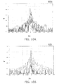
- FIGS. 5A and 5B are schematic views illustrating characteristics of the optical elements.
- FIG. 5A illustrates the characteristic of the optical element 510 according to this embodiment
- FIG. 5B illustrates the characteristic of the optical element 519 of the comparative example.
- FIG. 5A corresponds to the characteristic of the state of use illustrated in FIG. 4A or FIG. 4B.
- FIG. 5A and FIG. 5B illustrate the images perceived when the human viewer 100 views the display content 180 of the image included in the image projection unit 115 via the optical element 510 or the optical element 519.
- the display content 180 is not formed in a double image; and the display content 180 is perceived clearly.
- the display content 180 is formed in a double image and is perceived unclearly.
- the optical element 510 suppresses the image presented to the human viewer 100 from being a double image by the reflection angle of the light reflected by the first major surface 10a being different from the reflection angle of the light reflected by the second major surface 10b by the optical axis 13oa of the first Fresnel lens 10f being disposed at a position different from the position of the outline center 13s of the first major surface 10a.
- this embodiment can improve the ease of viewing the HUD.
- the first major surface 10a including the first Fresnel lens 10f is capable of transmitting and reflecting
- the first major surface 10a functions as a concave mirror that enlarges the reflected image.
- an optical component having the function of enlarging the image included in the image projection unit 115 can be omitted; or the specifications of such an optical component can be relaxed.
- the image projection unit 115 can be downsized, Further, by using a Fresnel lens instead of a normal lens as the optical element 510, the optical element 510 can be thinner.
- an optical element can be provided to improve the ease of viewing a HUD and downsize the display apparatus 310, In the display apparatus 310, it is possible to improve the ease of viewing while downsizing.
- FIG. 6 is a schematic view illustrating operations of the optical element according to the first embodiment of the invention.
- the first optical sheet 10 is illustrated as a simple plano-convex lens.
- a first incident light Lin1 incident on the second major surface 10b of the first optical sheet 10 passes through the first optical sheet 10, is reflected by the first major surface 10a, and emerges at a first reflection angle ⁇ out1 as a first reflected light Lout1.
- a second incident light Lin2 incident on the second major surface 10b of the first optical sheet 10 is reflected by the second major surface 10b at a second reflection angle ⁇ out2 as a second reflected light Lout2.
- the refractive index of the first optical sheet 10 is taken to be 1.492 (e.g., the value of the refractive index of PMMA); and the refractive index of the external environment of the first optical sheet 10 is taken to be 1.0 (the value of the refractive index of air).
- the angle between the horizontal axis and the optical axis 13oa of the first optical sheet 10 is taken to be 45 degrees.
- the curvature radius of the first Fresnel lens 10f of the first optical sheet 10 is taken to be 750 mm (millimeters).
- a distance Zo from a position 101p of the eye 101 of the human viewer 100 to the center of the first optical sheet 10 is taken to be 800 mm.
- the width of a viewing region 114c at the position of the human viewer 100 is taken to be 60 mm.
- the conditions at which a double image substantially does not occur are the conditions at which the first reflected light Lout1 reflected by the first major surface 10a of the first optical sheet 10 and the second reflected light Lout2 reflected by the second major surface 10b are not simultaneously incident on the viewing region 114c.
- a double image substantially does not occur in the case where the first reflection angle ⁇ out1 of the first reflected light Lout1 is different from the second reflection angle ⁇ out2 of the second reflected light Lout2 by not less than 5 degrees.
- the optical element 510 it is desirable for the first reflection angle ⁇ out1 of the reflected light incident on the second major surface 10b and reflected by the first major surface 10a to be different from the second reflection angle ⁇ out2 of the reflected light reflected by the second major surface 10b by not less than 5 degrees.
- the conditions at which the first reflection angle ⁇ out1 is different from the second reflection angle ⁇ out2 by not less than 5 degrees are the conditions at which the distance between the optical axis 13oa and the outline center 13s is not less than 15 mm.
- the distance from the position of the optical axis 13oa of the first Fresnel lens 10f at the first major surface 10a to the position of the outline center 13s of the first major surface 10a is not less than 15 mm.
- each of the ridge portions 12 of the first Fresnel lens 10f provided in the first optical sheet 10 of the optical element 510 is substantially unperceivable to the human viewer 100.
- the vision of the human viewer 100 is 1.0
- two points separated from each other by a distance of 0.3 mm can be identified when disposed at a location 1 m from the human viewer 100.
- the width of the ridge portion 12 of the first Fresnel lens 10f it is desirable for the width of the ridge portion 12 of the first Fresnel lens 10f to be not more than 0.3 mm.
- the vision of the human viewer 100 is, for example, 0.7
- two points separated from each other by a distance of 0.43 mm can be identified when disposed at a location 1 m from the human viewer 100.
- the first Fresnel lens 10f includes the multiple ridge portions 12 having concentric circular configurations centered on the optical axis 13oa; and the width of each of the multiple ridge portions 12 along the radial direction from the optical axis 13oa toward the outside of the concentric circles may be set to be not more than 0.43 mm.
- the ridge portions 12 are substantially unperceivable; and the ease of viewing the HUD improves further.
- the width of the ridge portion 12 may be set in a range in which diffraction does not occur.
- the first Fresnel lens 10f includes the multiple ridge portions 12 having concentric circular configurations centered on the optical axis 13oa; and it is desirable for the width of each of the multiple ridge portions 12 along the radial direction from the optical axis 13oa toward the outside of the concentric circles to be not less than 0.01 mm.
- the first major surface 10a of the optical element 510 is capable of reflecting and transmitting visible light.
- the absorbency index to be 0 the transmittance of the first major surface 10a with respect to visible light can be taken to be not less than 70%.
- the reflectance of the first major surface 10a with respect to visible light is less than 30%.
- the first major surface 10a of the optical element 510 can reflect and transmit.
- a Fresnel lens may be used to enlarge or reduce an image by refracting transmitted light, in such a case, the Fresnel lens transmits but substantially does not reflect.
- a Fresnel lens may be used as a mirror to enlarge or reduce a reflected image, in such a case, the Fresnel lens reflects but substantially does not transmit.
- the optical element 510 is used as the reflecting unit 711 that reflects the light flux 112 in, for example, a HUD, it is necessary to efficiently reflect the light flux 112 and simultaneously transmit the light of the scenery image of the external environment. Accordingly, the optical element 510 is capable of reflecting and transmitting visible light.
- the optical element 510 is capable of reflecting and transmitting visible light.
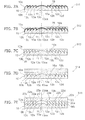
- FIGS. 7A to 7E are schematic cross-sectional views illustrating the configurations of optical elements according to the first embodiment of the invention.
- an optical element 511 further includes, in addition to the first optical sheet 10, a transmissive reflective optical layer 15 provided in the first major surface 10a of the first optical sheet 10 and capable of reflecting and transmitting visible light. Otherwise, the optical element 511 is similar to the optical element 510, and a description is therefore omitted.
- the transmissive reflective optical layer 15 may include, for example, a thin film of a metal such as aluminum, etc., a thin film of a metal oxide and the like, an organic thin film, etc.
- the thickness of the transmissive reflective optical layer 15 is controlled to be a thickness at which the transmissive reflective optical layer 15 is capable of reflecting and transmitting.
- the transmissive reflective optical layer 15 may be a single-layer film or a stacked multiple-layer film.
- the transmissive reflective optical layer 15 also may include an AR coating layer used in antireflective layers.
- a dielectric multiple-layer film may be used as the AR coating film. In the case where the dielectric multiple-layer film is used, the reflectance can be controlled by the incident angle; the reflectance at the desired incident angle can be increased; and the efficiency can be increased.
- any method such as dry film formation methods such as vapor deposition, sputtering, CVD, etc., wet film formation methods such as coating, etc., may be employed as the formation method of the transmissive reflective optical layer 15.
- an optical element 512 further includes, in addition to the first optical sheet 10 and the transmissive reflective optical layer 15, a first transparent layer 18a.
- the first transparent layer 18a is provided on the first major surface 10a side of the first optical sheet 10 and is transparent to visible light.
- the first transparent layer 18a is provided on the side of the transmissive reflective optical layer 15 opposite to the first optical sheet 10. Otherwise, the optical element 512 is similar to the optical element 511, and a description is therefore omitted.
- the first transparent layer 18a may include, for example, a transparent resin such as an acrylic resin.
- the first transparent layer 18a functions as, for example, an adhesive layer.
- the first transparent layer 18a can be used to adhere the optical element 512 to, for example, the windshield 710a.
- the refractive index of the first transparent layer 18a may be substantially the same as the refractive index of the windshield 710a.
- an optical element 513 includes the first optical sheet 10 and further includes a first high refractive index layer 16a provided on the first major surface 10a of the first optical sheet 10 and having a refractive index higher than that of the first optical sheet 10. Otherwise, the optical element 513 is similar to the optical element 510, and a description is therefore omitted.
- the first high refractive index layer 16a has a refractive index higher than that of the first optical sheet 10, the first major surface 10a is capable of reflecting and transmitting.
- the first high refractive index layer 16a may include, for example, a compound layer such as a metal oxide film, a resin layer, etc., having a refractive index higher than that of the first optical sheet 10.
- an optical element 514 further includes, in addition to the first optical sheet 10 and the first high refractive index layer 16a, a second transparent layer 18b.
- the second transparent layer 18b is provided on the first major surface 10a of the first optical sheet 10 and is transparent to visible light.
- the second transparent layer 18b is provided on the side of the first high refractive index layer 16a opposite to the first optical sheet 10. Otherwise, the optical element 514 is similar to the optical element 513, and a description is therefore omitted.
- the second transparent layer 18b may include, for example, a transparent resin sheet of PET and the like. Thereby, for example, the first high refractive index layer 16a can be protected; and the reliability of the optical element 514 can be increased.
- the first transparent layer 18a recited above may be further provided on the side of the second transparent layer 18b opposite to the first optical sheet 10. In such a case as well, the first transparent layer 18a functions, for example, as an adhesive layer.
- the refractive indexes of the first transparent layer 18a and the second transparent layer 18b may be substantially the same as the refractive index of the windshield 710a. Thereby, reflections between the first transparent layer 18a, the second transparent layer 18b, and the windshield 710a can be suppressed; and a bright display can be obtained. Further, the refractive index of the first transparent layer 18a may be set to a value between the refractive index of the second transparent layer 18b and the refractive index of the windshield 710a. Thereby, the reflections between the first transparent layer 18a, the second transparent layer 18b, and the windshield 710a can be suppressed; and a bright display can be obtained.
- an optical element 515 further includes, in addition to the first optical sheet 10, a second optical sheet 20 and a second high refractive index layer 16b. Otherwise, the optical element 515 is similar to the optical element 510, and a description is therefore omitted.
- the second optical sheet 20 includes a second Fresnel lens 20f provided in a third major surface 20a opposing the first major surface 10a.
- the second Fresnel lens 20f is a concave Fresnel lens; and in the case where the first Fresnel lens 10f is a concave Fresnel lens, the second Fresnel lens 20f is a convex Fresnel lens.
- the first Fresnel lens 10f is a convex Fresnel lens
- the second Fresnel lens 20f is a concave Fresnel lens.
- the second high refractive index layer 16b is provided between the first optical sheet 10 and the second optical sheet 20.
- the second high refractive index layer 16b has a refractive index higher than the refractive index of the first optical sheet 10.
- the refractive index of the second high refractive index layer 16b may be set to be higher than the refractive index of the second optical sheet 20.
- the optical axis 13oa of the first Fresnel lens 10f is disposed at a position different from the position of the center (the outline center 13s) of the outline of the first major surface 10a.
- the position of an optical axis 23oa of the second Fresnel lens 20f is substantially matched to the position of the optical axis 13oa of the first Fresnel lens 10f.
- the outline of the third major surface 20a of the second Fresnel lens 20f is, for example, the same as the outline of the first Fresnel lens 10f.
- the optical axis 23oa of the second Fresnel lens 20f at the third major surface 20a is disposed at a position different from the position of the center of the outline of the third major surface 20a.
- a recess 21 having a concave curved surface is provided in the third major surface 20a of the second Fresnel lens 20f; and multiple groove portions 22 (e.g., a groove portion 22a, a groove portion 22b, a groove portion 22c, a groove portion 22d, etc. from a center 23o of the concentric circles toward the outside) having curved surfaces are provided in concentric circular configurations around the recess 21. Thereby, the second Fresnel lens 20f is formed.
- the thickness of the portion of each of the groove portions 22 on the side proximal to the center 23o is less than the thickness of the portion on the side distal to the center 13o.
- a fourth major surface 20b on the side opposite to the third major surface 20a is substantially a plane.
- the multiple ridge portions 12 of the first Fresnel lens 10f oppose the multiple groove portions 22 of the second Fresnel lens 20f respectively.
- the first Fresnel lens 10f includes the multiple ridge portions 12 having concentric circular configurations centered on the optical axis 13oa of the first Fresnel lens 10f; and the second Fresnel lens 20f includes the multiple groove portions 22 having concentric circular configurations centered on the optical axis 23oa of the second Fresnel lens 20f.
- the width of the ridge portion 12 positioned a distance (the first distance) along the radial direction from the optical axis 13oa of the first Fresnel lens 10f toward the outside of the concentric circles is substantially the same as the width of the groove portion 22 positioned the first distance recited above along the radial direction from the optical axis 23oa of the second Fresnel lens 20f toward the outside of the concentric circles.
- the curvature of the groove portion 22 may be set to be substantially equal to the curvature of the ridge portion 12.
- the first major surface 10a of the first optical sheet 10 is capable of reflecting and transmitting.
- the second optical sheet 20 in addition to the first optical sheet 10, the shift of the optical path when light passes through the ridge portion 12 can be corrected by the second optical sheet 20. Thereby, the distortion of the image of the scenery of the external environment can be suppressed.
- the ease of viewing the HUD can be improved.
- the positions of the multiple images generated by the first major surface 10a and the second major surface 10b of the optical element can be changed from each other; and overlapping of these images is suppressed.
- a Fresnel mirror surface which performs the role of a concave mirror interposed between planes frontward and rearward, is used. Then, by shifting the optical axis of the Fresnel mirror surface from the center of the outline of the Fresnel mirror surface, the perception of multiple images is suppressed.
- an optical element such as the reflecting unit 711 of the HUD, it is possible to downsize the display apparatus while improving the ease of viewing the HUD.
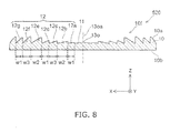
- the optical element 520 includes the first optical sheet 10 including the first Fresnel lens 10f provided in the first major surface 10a, where the first Fresnel lens 10f includes the multiple ridge portions 12 having concentric circular configurations.
- the optical element 520 also may be adhered, for example, to the windshield 710a of the vehicle 730 and used as the reflecting unit 711 of the HUD.
- the first major surface 10a is capable of reflecting and transmitting visible light.
- the widths along the radial direction from the center 13o of the concentric circles toward the outside of mutually adjacent ridge portions 12 are different from each other.
- the width along the radial direction of each of the multiple ridge portions 12 is not more than a predetermined length.
- the ridge portion 12a, the ridge portion 12b, the ridge portion 12c, the ridge portion 12d, a ridge portion 12e, a ridge portion 12f, a ridge portion 12g, etc. are provided from the inner side of the concentric circles as illustrated in FIG.
- the widths of mutually adjacent ridge portions 12 are different from each other. Thereby, a fringe pattern due to diffraction effects of the ridge portions 12 can be suppressed.
- the width of the ridge portion 12 is set to be not more than a predetermined length.
- a length for which two of the ridge portions 12 are substantially unidentifiable can be employed as the predetermined width based on the vision of the human viewer 100 and the distance between the human viewer 100 and the optical element 520. Thereby, each of the multiple ridge portions 12 is not recognized; and the fringe pattern due to the multiple ridge portions 12 is not perceived.
- 0.43 mm can be employed as the predetermined width recited above assuming the case where the vision of the human viewer 100 is 0.7 and the distance between the human viewer 100 and the optical element 520 is 1 m. In other words, it is desirable for the width of the ridge portion 12 to be not more than 0.43 mm.
- the width of the ridge portion 12 may be not more than 0.3 mm.
- the fringe pattern due to the diffraction effects is perceived more easily in the case where the widths of the ridge portions 12 are reduced in a state of the width being constant between the ridge portions 12.
- the ridge portions 12 themselves are perceived.
- the diffraction effects are suppressed by mutually adjacent ridge portions 12 of the multiple ridge portions 12 having widths different from each other while setting the widths of the ridge portions 12 to values small enough that the ridge portions 12 themselves are not perceived.
- the ridge portions 12 themselves substantially are not perceived while the fringe pattern due to the diffraction effects is suppressed.
- the ease of viewing the HUD can be improved.
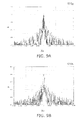
- FIGS. 9A and 9B and FIGS. 10A and 10B are graphs illustrating characteristics of optical elements.
- FIG. 9A illustrates the characteristic of an optical element 520a in the case where the widths of the ridge portions 12 change within 0.28 mm ⁇ 0.10 mm (e.g., the case where the first width w1 is 0.28 mm, the second width w2 is 0.28 mm + 0.10 mm, and the third width w3 is 0.28 mm - 0.10 mm).
- FIG. 9B illustrates the characteristic of an optical element 520b in the case where the widths of the ridge portions 12 change within 0.28 mm ⁇ 0.05 mm (e.g., the case where the first width w1 is 0.28 mm, the second width w2 is 0.28 mm + 0.05 mm, and the third width w3 is 0.28 mm - 0.05 mm).
- FIG. 10A illustrates the characteristic of an optical element 520c in the case where the widths of the ridge portions 12 change within 0.28 mm ⁇ 0,02 mm (e.g., the case where the first width w1 is 0.28 mm, the second width w2 is 0.28 mm + 0.02 mm, and the third width w3 is 0.28 mm - 0.02 mm).
- FIG. 10B illustrates the characteristic of an optical element 529 of a comparative example in the case where the widths of the ridge portions 12 are constant at 0.28 mm.
- the diffraction effects can be reduced further; and it is more difficult to perceive the fringe pattern.
- any two mutually adjacent ridge portions 12 of the multiple ridge portions 12 may have mutually different widths.
- the widths of any two mutually adjacent ridge portions 12 may be set to be different from each other at the central portion of the optical element 520 where the fringe pattern is practically noticeable easily.
- the width of the ridge portion 12a is the first width w1; the width of the ridge portion 12b is the second width w2; the width of the ridge portion 12c is the first width w1; the width of the ridge portion 12d is the first width w1; the width of the ridge portion 12e is the second width w2; the width of the ridge portion 12f is the third width w3; and the width of the ridge portion 12g is the first width w1.
- the second width w2 is different from the first width w1; the third width w3 is different from the first width w1; and the third width w3 is different from the second width w2.
- the mutually adjacent ridge portion 12c and ridge portion 12d have the same width of the first width w1.
- the value of twice the first width w1 i.e., the total of the widths of the two adjacent ridge portions 12 along the radial direction, is set to be not more than the predetermined length.
- a length for which two of the ridge portions 12 are substantially unidentifiable can be employed as the predetermined width based on the vision of the human viewer 100 and the distance between the human viewer 100 and the optical element 520. Thereby, each of the multiple ridge portions 12 is not recognized; and the fringe pattern due to the multiple ridge portions 12 is not perceived.
- 0.43 mm can be employed as the predetermined width recited above.
- the diffraction effects are suppressed by the total of two adjacent ridge portions 12 being not more than a predetermined length (e.g., 0.43 mm) even in the case where the widths of mutually adjacent ridge portions 12 of the multiple ridge portions 12 are the same.
- a predetermined length e.g. 0.43 mm
- one of two ridge portions 12 on either adjacent side of one ridge portion 12 has a width along the radial direction from the center of the concentric circles toward the outside that is different from the width of the one ridge portion recited above; and the other of the two ridge portions recited above has a width along the radial direction substantially the same as the width of the one ridge portion recited above.
- the widths of the three continuously arranged ridge portions 12 are not the same. However, if the widths of the three continuously arranged ridge portions 12 are the same, the diffraction effects can be suppressed by the total of the widths of the three continuously arranged ridge portions 12 being not more than a predetermined length (e.g., 0.43 mm); and the ease of viewing the HUD can be improved.
- a predetermined length e.g. 0.43 mm
- the trench spacing (i.e., the widths of the ridge portions 12) of the Fresnel lens is set to have a multiply periodic spacing or a randomly periodic spacing instead of using uniformly-spaced trenches or trenches with uniform heights.
- the diffraction due to the Fresnel lens can be suppressed by breaking the periodicity.
- a Fresnel lens having, for example, a triple periodic spacing such as that recited above can be applied.
- the widths of the ridge portions 12 change from the first width w1 to the second width w2 to the third width w3, and then change repeatedly in this order.
- the order of the widths of the ridge portions 12 is arbitrary and may be the order of the third width w3 to the second width w2 to the first width w1. Any width selected from the first width w1, the second width w2, and the third width w3 may be applied to the widths of the ridge portions 12.
- the widths of the ridge portions 12 may change, for example, at random.
- the optical element 520 may further include the transmissive reflective optical layer 15 provided on the first major surface 10a of the first optical sheet 10 and capable of reflecting and transmitting visible light.
- the transmittance of the transmissive reflective optical layer 15 with respect to visible light may be set to be not less than 70%.
- the optical element 520 may further include the first transparent layer 18a provided on the first major surface 10a side of the first optical sheet 10 and being transparent to visible light.
- the first transparent layer 18a which functions as an adhesive layer may be provided on the side of the transmissive reflective optical layer 15 opposite to the first optical sheet 10.
- the optical element 520 may further include the first high refractive index layer 16a provided on the first major surface 10a of the first optical sheet 10 and having a refractive index higher than that of the first optical sheet 10. Thereby, the first major surface 10a can reflect and transmit.
- the optical element 520 may further include, in addition to the first optical sheet 10 and the first high refractive index layer 16a, the second transparent layer 18b (e.g., an optical film) provided on the first major surface 10a of the first optical sheet 10 and transparent to visible light.
- the second transparent layer 18b may, for example, protect the first high refractive index layer 16a and increase the reliability of the optical element 514.
- the optical element 520 may further include: the second optical sheet 20 including the second Fresnel lens 20f provided in the third major surface 20a opposing the first major surface 10a; and the second high refractive index layer 16b provided between the first optical sheet 10 and the second optical sheet 20 and having a refractive index higher than the refractive index of the first optical sheet 10.
- the multiple ridge portions 12 of the first Fresnel lens 10f oppose the multiple groove portions 22 of the second Fresnel lens 20f respectively.
- the first Fresnel lens 10f includes the multiple ridge portions 12 having concentric circular configurations centered on the optical axis 13oa of the first Fresnel lens 10f; and the second Fresnel lens 20f includes the multiple groove portions 22 having concentric circular configurations centered on the optical axis 23oa of the second Fresnel lens 20f.
- the width of the ridge portion 12 positioned a distance (the first distance) along the radial direction from the optical axis 13oa of the first Fresnel lens 10f toward the outside of the concentric circles is substantially the same as the width of the groove portion 22 positioned the first distance recited above along the radial direction from the optical axis 23oa of the second Fresnel lens 20f toward the outside of the concentric circles.
- the curvature of the groove portion 22 can be set to be substantially equal to the curvature of the ridge portion 12.
- the shift of the optical path when light passes through the ridge portion 12 can be corrected by the second optical sheet 20; the distortion of the image of the scenery of the external environment can be suppressed; and the ease of viewing the HUD can be improved further.
- the optical axis 13oa of the first Fresnel lens 10f at the first major surface 10a may be disposed at a position different from the position of the center (the outline center 13s) of the outline of the first major surface 10a.
- FIG. 12 is a schematic view illustrating the configuration of the display apparatus according to the third embodiment of the invention.
- the display apparatus 330 includes the image projection unit 115 that projects a light flux including an image toward the human viewer 100 by using the optical element 510 according to this embodiment of the invention to reflect the light flux.
- the display apparatus 330 may further include the optical element 510.
- the display apparatus 330 may further include the image data generation unit 130
- the image data generation unit 130 may be omitted in some cases. It is not always necessary to provide the image data generation unit 130 integrally with the image projection unit 115; and the image data generation unit 130 may be disposed, for example, not in the interior of the dashboard 720 but at any location of the vehicle 730.
- the image data from the image data generation unit 130 may be supplied to the image projection unit 115 using a wired or wireless method of electrical signals, optical signals, and the like.
- the image light formation unit 110 includes, for example, a light source 111 and an image formation unit 117.
- the light source 111 emits the light from which the light flux 112 is formed.
- the light source 111 may include various components such as LEDs (Light Emitting Diodes), high pressure mercury lamps, halogen lamps, lasers, etc.
- the image light formation unit 110 further includes a tapered light guide 116 provided between the light source 111 and the image formation unit 117.
- the light emitted from the light source 111 is controlled by the tapered light guide 116 to have a divergence angle somewhat within a range.
- the image formation unit 117 By passing through the image formation unit 117, the light becomes the light flux 112 including the image; and the divergence angle of the light flux 112 is controlled to be somewhat within a range.
- the light flux projection unit 120 projects the light flux 112 emitted from the image light formation unit 110 toward the human viewer 100 by using the optical element according to this embodiment included in the windshield unit 710 of the vehicle 730 to reflect the light flux 112.
- the optical element 510 is used in this specific example, any of the optical elements according to the embodiments of the invention and optical elements of modifications thereof may be used as the optical element.
- the light flux projection unit 120 may include, for example, various lenses, mirrors, and various optical elements that control the divergence angle (the diffusion angle).
- the light flux projection unit 120 includes a light source side lens 123, an aperture 124, an emerging side lens 125, and an emerging side mirror 126.
- the light source side lens 123 is disposed between the image light formation unit 110 and the emerging side mirror 126; the aperture 124 is disposed between the light source side lens 123 and the emerging side mirror 126; and the emerging side lens 125 is disposed between the aperture 124 and the emerging side mirror 126.
- the emerging side mirror 126 may include a plane mirror.
- a plane mirror can be used as the emerging side mirror 126; and the light flux projection unit 120 (i.e., the image projection unit 115) can be downsized.
- the divergence angle of the light flux 112 is controlled; and a design is possible in which the light flux 112 is incident on the eye 101 of the human viewer 100.
- the human viewer 100 can view the image included in the light flux 112 using one eye 101.
- the difficulty of viewing due to the binocular parallax occurring when the image 181 of the display content 180 reflected by the windshield unit 710 is viewed with both eyes can be eliminated.
- the windshield unit 710 may be disposed at a position such that the distance from the human viewer 100 is not less than 21.7 cm. Thereby, the sense of depth perceived by the human viewer 100 is increased; and it is easy for the display content 180 to be perceived at the desired depthward position.
- the embodiments of the invention are not limited thereto.
- the light flux 112 emitted from the image projection unit 115 may be incident on both eyes of the human viewer 100.
- the divergence angle of the light flux 112 can be controlled; and a projection region 114 of the light flux 112 can be controlled in a constant range at the position of the human viewer 100.
- the size (the width in the left and right direction) of the projection region 114 of the light flux 112 at the position of the human viewer 100 may be set to be, for example, not more than about 60 mm to 75 mm in the case where the viewing is performed with one eye 101.
- the size of the projection region 114 may be controlled mainly by the optical element included in the light flux projection unit 120.
- a projection position 114a of the light flux 112 at the position of the human viewer 100 can be controlled, for example, by changing the placement position and the angle of the image projection unit 115.
- the projection position 114a can be controlled by changing at least one selected from the placement position of the image light formation unit 110, the angle of the image light formation unit 110, the placement position of the light flux projection unit 120, and the angle of the light flux projection unit 120.
- the display apparatus 330 may further include a control unit 250 that controls the projection position 114a of the light flux 112 at the position of the human viewer 100 by controlling the image projection unit 115.
- the projection position 114a may be controlled by the control unit 250 by, for example, controlling the angle of the emerging side mirror 126.
- control unit 250 includes a control signal unit 251 and a drive unit 126a.
- the control signal unit 251 outputs a control signal to the drive unit 126a to operate the drive unit 126a.
- the drive unit 126a includes a motor and the like that changes, for example, the angle, position, etc., of the emerging side mirror 126.
- the drive unit 126a is operated by the control signal output from the control signal unit 251, changes the angle, position, etc., of the emerging side mirror 126, and changes the projection position 114a of the light flux 112 at the position of the human viewer 100.
- the drive unit 126a may be considered to be included in the image projection unit 115.
- each of the image light formation unit 110 and the light flux projection unit 120 Various modifications of the configuration of each of the image light formation unit 110 and the light flux projection unit 120 are possible.
- the dispositions of the components included in the image light formation unit 110 and the components included in the light flux projection unit 120 are arbitrary.
- the image light formation unit 110 (and the components included therein) may be inserted between the components included in the light flux projection unit 120.
- a display method according to a fourth embodiment of the invention is a display method using the optical element described in regard to the first embodiment.
- the display method includes: causing the light flux 112 including the image to be incident on the first optical sheet 10 from the second major surface 10b side, where the first optical sheet 10 includes the first Fresnel lens 10f provided in the first major surface 10a, and the second major surface 10b is on the side opposite to the first major surface 10a; changing the direction of the second major surface reflection light flux (the second reflected light Lout2) of the light flux 112 reflected by the second major surface 10b to be not less than 5 degrees from the direction of the first major surface reflection light flux (the first reflected light Lout1) of the light flux 112 reflected by the first major surface 10a; and projecting the first major surface light flux toward the human viewer 100.
- the second reflection angle ⁇ out2 of the second reflected light Lout2 is changed to be not less than 5 degrees from the first reflection angle ⁇ out1 of the first reflected light Lout1; and the first reflected light Lout1 is projected toward the human viewer 100.
- a double image can be suppressed; and an easily-viewable display can be realized.
- a moving body according to a fifth embodiment of the invention includes any of the optical elements according to the embodiments of the invention as illustrated in FIGS. 1A and 1B and a transparent plate (the windshield 710a and the windshield unit 710) supporting the optical element.
- the moving body may further include a display apparatus including the image projection unit 115 that projects the light flux 112 including an image toward the human viewer 100 by using the optical element according to this embodiment to reflect the light flux 112.
- the image projection unit 115 can control the divergence angle of the light flux including the image and project the light flux toward the optical element.
- the moving body according to this embodiment may be any means of transportation such as a vehicle, ship, aircraft, etc.
- any optical element according to this embodiment may be adhered to the windshield unit 710 of the moving body, the optical element may be built into the windshield unit 710. Such examples will now be described.
- FIGS. 13A and 13B are schematic cross-sectional views illustrating configurations of portions of moving bodies according to the fifth embodiment of the invention.
- a windshield 710a1 of the moving body includes a first transparent plate 715a, a second transparent plate 715b, and an optical element provided between the first transparent plate 715a and the second transparent plate 715b.
- the optical element 512 described above is used as the optical element.
- a transparent resin layer 715c is provided in the portion between the first transparent plate 715a and the second transparent plate 715b where the optical element 512 is not provided.
- the material of the transparent resin layer 715c may be, for example, the same as the material of the first transparent layer 18a.
- the optical element 515 described above is provided between the first transparent plate 715a and the second transparent plate 715b of the windshield 710a1 of the moving body according to this embodiment.
- the transparent resin layer 715c is provided in the portion between the first transparent plate 715a and the second transparent plate 715b where the optical element 512 is not provided.
- the first transparent plate 715a and the second transparent plate 715b may include transparent substrates made of, for example, glass substrates or a resin.
- any of the optical elements according to the embodiments of the invention can be provided between the first transparent plate 715a and the second transparent plate 715b.
- optical elements, display apparatuses, display methods, and moving bodies practicable by an appropriate design modification by one skilled in the art based on the optical elements, the display apparatuses, the display methods, and the moving bodies described above as embodiments of the invention also are within the scope of the invention to the extent that the purport of the invention is included.
Landscapes
- Physics & Mathematics (AREA)
- General Physics & Mathematics (AREA)
- Optics & Photonics (AREA)
- Engineering & Computer Science (AREA)
- Multimedia (AREA)
- Mechanical Engineering (AREA)
- Instrument Panels (AREA)
- Lenses (AREA)
- Optical Elements Other Than Lenses (AREA)
Applications Claiming Priority (1)
| Application Number | Priority Date | Filing Date | Title |
|---|---|---|---|
| JP2010060209A JP2011191715A (ja) | 2010-03-17 | 2010-03-17 | 光学素子、表示装置、表示方法、及び、移動体 |
Publications (2)
| Publication Number | Publication Date |
|---|---|
| EP2372407A2 true EP2372407A2 (fr) | 2011-10-05 |
| EP2372407A3 EP2372407A3 (fr) | 2012-04-04 |
Family
ID=44115682
Family Applications (1)
| Application Number | Title | Priority Date | Filing Date |
|---|---|---|---|
| EP11153328A Withdrawn EP2372407A3 (fr) | 2010-03-17 | 2011-02-04 | Élément optique avec une lentille de Fresnel, appareil d'affichage, procédé d'affichage et corps en mouvement |
Country Status (5)
| Country | Link |
|---|---|
| US (1) | US8659840B2 (fr) |
| EP (1) | EP2372407A3 (fr) |
| JP (1) | JP2011191715A (fr) |
| KR (1) | KR101196967B1 (fr) |
| CN (2) | CN103454704B (fr) |
Cited By (2)
| Publication number | Priority date | Publication date | Assignee | Title |
|---|---|---|---|---|
| WO2020228072A1 (fr) * | 2019-05-14 | 2020-11-19 | 深圳市歌美迪电子技术发展有限公司 | Boîtier, rétroviseur et automobile |
| US11073688B2 (en) | 2015-12-24 | 2021-07-27 | Starbreeze Ip Lux Ii S.À R.L. | Virtual reality head mounted display having planar fresnel surface |
Families Citing this family (60)
| Publication number | Priority date | Publication date | Assignee | Title |
|---|---|---|---|---|
| JP5275963B2 (ja) | 2009-12-08 | 2013-08-28 | 株式会社東芝 | 表示装置、表示方法及び移動体 |
| JP2012027273A (ja) * | 2010-07-23 | 2012-02-09 | Nikon Corp | レンズ装置および表示システム |
| US9632315B2 (en) | 2010-10-21 | 2017-04-25 | Lockheed Martin Corporation | Head-mounted display apparatus employing one or more fresnel lenses |
| US10359545B2 (en) * | 2010-10-21 | 2019-07-23 | Lockheed Martin Corporation | Fresnel lens with reduced draft facet visibility |
| JP2012179935A (ja) * | 2011-02-28 | 2012-09-20 | Jvc Kenwood Corp | 車両用表示装置 |
| JP5458080B2 (ja) | 2011-09-28 | 2014-04-02 | 株式会社東芝 | 表示装置 |
| JP5734888B2 (ja) | 2012-01-31 | 2015-06-17 | 株式会社東芝 | 表示装置、移動体、及び、表示装置の設置方法 |
| CN103454767B (zh) * | 2012-06-01 | 2017-01-11 | 联想(北京)有限公司 | 显示设备、显示方法和用于显示设备的光学构件 |
| WO2014041688A1 (fr) * | 2012-09-14 | 2014-03-20 | パイオニア株式会社 | Élément optique et afficheur tête haute |
| WO2014041689A1 (fr) * | 2012-09-14 | 2014-03-20 | パイオニア株式会社 | Afficheur tête haute |
| JPWO2014041690A1 (ja) * | 2012-09-14 | 2016-08-12 | パイオニア株式会社 | 光学素子及びヘッドアップディスプレイ |
| WO2014041691A1 (fr) * | 2012-09-14 | 2014-03-20 | パイオニア株式会社 | Élément optique et afficheur tête haute |
| US9057826B2 (en) * | 2013-01-31 | 2015-06-16 | Google Inc. | See-through near-to-eye display with eye prescription |
| US9159301B2 (en) * | 2013-05-07 | 2015-10-13 | Honda Motor Co., Ltd. | Slanted map |
| TWI489140B (zh) * | 2014-02-24 | 2015-06-21 | Quanta Comp Inc | 頭戴式顯示裝置 |
| JP2015161732A (ja) | 2014-02-26 | 2015-09-07 | 矢崎総業株式会社 | 表示光投影用光学デバイス |
| JPWO2015159523A1 (ja) * | 2014-04-14 | 2017-04-13 | パナソニックIpマネジメント株式会社 | ヘッドアップディスプレイ、およびヘッドアップディスプレイを搭載した移動体 |
| JP6603883B2 (ja) | 2014-04-14 | 2019-11-13 | パナソニックIpマネジメント株式会社 | ヘッドアップディスプレイ、およびヘッドアップディスプレイを搭載した移動体 |
| WO2015177833A1 (fr) * | 2014-05-19 | 2015-11-26 | パイオニア株式会社 | Élément de génération d'image virtuelle et dispositif d'affichage tête haute |
| USD744155S1 (en) * | 2014-05-28 | 2015-11-24 | Osram Sylvania Inc. | Lens |
| JP2016018103A (ja) * | 2014-07-09 | 2016-02-01 | セイコーエプソン株式会社 | 光学素子、及び表示装置 |
| JP2016029412A (ja) * | 2014-07-25 | 2016-03-03 | 株式会社東芝 | 光学装置 |
| US10684476B2 (en) | 2014-10-17 | 2020-06-16 | Lockheed Martin Corporation | Head-wearable ultra-wide field of view display device |
| WO2016141054A1 (fr) | 2015-03-02 | 2016-09-09 | Lockheed Martin Corporation | Système d'affichage portable |
| JP6532744B2 (ja) * | 2015-04-21 | 2019-06-19 | キヤノンメディカルシステムズ株式会社 | 表示装置、および医用画像診断装置 |
| JP6540249B2 (ja) * | 2015-06-05 | 2019-07-10 | 大日本印刷株式会社 | 表示装置 |
| US10754156B2 (en) | 2015-10-20 | 2020-08-25 | Lockheed Martin Corporation | Multiple-eye, single-display, ultrawide-field-of-view optical see-through augmented reality system |
| JP6427095B2 (ja) * | 2015-12-24 | 2018-11-21 | 矢崎総業株式会社 | 表示光投影用光学システム |
| JP6387098B2 (ja) * | 2016-02-12 | 2018-09-05 | コミー株式会社 | 手荷物入れ用内部確認ミラーおよびその製造方法 |
| US9995936B1 (en) | 2016-04-29 | 2018-06-12 | Lockheed Martin Corporation | Augmented reality systems having a virtual image overlaying an infrared portion of a live scene |
| GB2552703B (en) * | 2016-08-04 | 2018-11-14 | Ford Global Tech Llc | A holographic display system |
| CN106125168A (zh) * | 2016-08-30 | 2016-11-16 | 乐视控股(北京)有限公司 | 一种菲涅尔透镜和虚拟现实设备 |
| US10890694B2 (en) | 2016-09-16 | 2021-01-12 | Valve Corporation | Optical system for head-mounted display system |
| JP2018146784A (ja) * | 2017-03-06 | 2018-09-20 | 矢崎総業株式会社 | 表示像投影装置および表示像投影システム |
| JP2018144648A (ja) * | 2017-03-06 | 2018-09-20 | 矢崎総業株式会社 | 表示像投影システム |
| JP2017137054A (ja) * | 2017-04-26 | 2017-08-10 | パイオニア株式会社 | ヘッドアップディスプレイ |
| CN109031661A (zh) * | 2017-06-12 | 2018-12-18 | 宏碁股份有限公司 | 虚拟实境显示装置 |
| US20230125258A1 (en) * | 2017-07-03 | 2023-04-27 | Holovisions LLC | Augmented Reality (AR) Eyewear with a Section of a Fresnel Reflector Comprising Individually-Adjustable Transmissive-Reflective Optical Elements |
| US11163163B2 (en) * | 2017-07-03 | 2021-11-02 | Holovisions | Augmented reality (AR) eyewear with at least one quasi Fresnel reflector (QFR) |
| CN109471260A (zh) * | 2017-09-08 | 2019-03-15 | 塔普翊海(上海)智能科技有限公司 | 目镜式成像光学装置和头戴式成像光学设备及其制造方法和成像方法 |
| KR102547822B1 (ko) * | 2017-11-24 | 2023-06-26 | 삼성전자주식회사 | Hud 시스템 및 hud를 위한 광학 소자 |
| JP2019109434A (ja) | 2017-12-20 | 2019-07-04 | セイコーエプソン株式会社 | 表示装置 |
| JP2019109435A (ja) * | 2017-12-20 | 2019-07-04 | セイコーエプソン株式会社 | 表示装置 |
| CN108152959B (zh) * | 2018-01-02 | 2020-08-07 | 京东方科技集团股份有限公司 | 车载抬头显示系统 |
| WO2019151498A1 (fr) * | 2018-02-01 | 2019-08-08 | コニカミノルタ株式会社 | Élément d'affichage et dispositif d'affichage |
| US10981358B2 (en) * | 2018-04-03 | 2021-04-20 | AGC Inc. | Laminated glass |
| CN108490727A (zh) * | 2018-06-07 | 2018-09-04 | 成都恒坤光显材料科技有限公司 | 一种新型的视角可控的正投影屏幕 |
| JP7124535B2 (ja) * | 2018-08-06 | 2022-08-24 | 大日本印刷株式会社 | 反射スクリーン、合わせガラス及び映像表示装置 |
| JP7087806B2 (ja) * | 2018-08-08 | 2022-06-21 | 大日本印刷株式会社 | 映像表示システム |
| WO2020110961A1 (fr) * | 2018-11-26 | 2020-06-04 | Agc株式会社 | Écran transparent de type à réflexion et système d'affichage d'image |
| JP2019069773A (ja) * | 2019-01-16 | 2019-05-09 | パイオニア株式会社 | ヘッドアップディスプレイ |
| US11236887B2 (en) | 2019-01-25 | 2022-02-01 | Eaton Intelligent Power Limited | Optical structures for light emitting diodes (LEDs) |
| USD903187S1 (en) * | 2019-01-25 | 2020-11-24 | Eaton Intelligent Power Limited | Optical structure |
| USD901752S1 (en) * | 2019-01-25 | 2020-11-10 | Eaton Intelligent Power Limited | Optical structure |
| JP7189507B2 (ja) * | 2019-03-19 | 2022-12-14 | コニカミノルタ株式会社 | 表示部材及び表示装置 |
| CN112485902B (zh) * | 2019-09-11 | 2023-07-21 | 深圳光峰科技股份有限公司 | 一种光学薄膜以及光学成像系统 |
| CN113539060A (zh) * | 2020-04-20 | 2021-10-22 | 华为技术有限公司 | 一种桌面显示装置和电子设备 |
| CN111458880B (zh) * | 2020-05-09 | 2022-04-22 | 三生万物(北京)人工智能技术有限公司 | 一种波导光场显示装置和头戴式增强现实眼镜 |
| JP2021002050A (ja) * | 2020-09-01 | 2021-01-07 | パイオニア株式会社 | ヘッドアップディスプレイ |
| CN113568144B (zh) * | 2021-07-22 | 2023-06-23 | 成都理想境界科技有限公司 | 光学成像镜组、扫描显示装置及近眼显示设备 |
Citations (1)
| Publication number | Priority date | Publication date | Assignee | Title |
|---|---|---|---|---|
| JPH11271665A (ja) | 1998-01-22 | 1999-10-08 | Central Glass Co Ltd | 表示装置 |
Family Cites Families (23)
| Publication number | Priority date | Publication date | Assignee | Title |
|---|---|---|---|---|
| JPH0658481B2 (ja) * | 1985-02-22 | 1994-08-03 | 株式会社ニコン | カメラの焦点板用多焦点距離フレネルレンズ |
| US4787722A (en) * | 1986-04-10 | 1988-11-29 | Fresnel Technologies, Inc. | Fresnel lens with aspiteric grooves |
| JP2770279B2 (ja) * | 1987-12-03 | 1998-06-25 | キヤノン株式会社 | 表示システム |
| JPH01147421A (ja) * | 1987-12-03 | 1989-06-09 | Canon Inc | 表示システム |
| US4904069A (en) * | 1987-12-14 | 1990-02-27 | Ichikoh Industries, Ltd. | Fresnel-type aspheric prism lens |
| CA1327468C (fr) * | 1988-09-12 | 1994-03-08 | Dennis F. Vanderwerf | Reflecteur de fresnel pour afficheur a cristaux liquides |
| JP3655972B2 (ja) * | 1996-08-16 | 2005-06-02 | 大日本印刷株式会社 | 反射型スクリーン及び前方投影システム |
| JP2000171613A (ja) | 1998-12-02 | 2000-06-23 | Kuraray Co Ltd | フレネルレンズシート |
| JP2000168352A (ja) * | 1998-12-10 | 2000-06-20 | Honda Access Corp | 車両用表示装置 |
| JP2000249965A (ja) * | 1999-02-26 | 2000-09-14 | Asahi Glass Co Ltd | 情報表示装置 |
| JP4372269B2 (ja) * | 1999-06-30 | 2009-11-25 | カルソニックカンセイ株式会社 | 拡大表示装置 |
| US6236511B1 (en) * | 2000-03-20 | 2001-05-22 | Rockwell Collins, Inc. | Beam combining optical element |
| US20020080495A1 (en) * | 2000-12-21 | 2002-06-27 | Raytheon Company | Method and apparatus for reducing distortion in a displayed image |
| JP2002287077A (ja) * | 2001-03-23 | 2002-10-03 | Nikon Corp | 映像表示装置 |
| JP2002311425A (ja) * | 2001-04-12 | 2002-10-23 | Omron Corp | 液晶表示装置 |
| JP2004077535A (ja) * | 2002-08-09 | 2004-03-11 | Dainippon Printing Co Ltd | フレネルレンズシート |
| JP2004177920A (ja) * | 2002-08-09 | 2004-06-24 | Olympus Corp | 投影観察装置 |
| US6952312B2 (en) * | 2002-12-31 | 2005-10-04 | 3M Innovative Properties Company | Head-up display with polarized light source and wide-angle p-polarization reflective polarizer |
| US7873233B2 (en) * | 2006-10-17 | 2011-01-18 | Seiko Epson Corporation | Method and apparatus for rendering an image impinging upon a non-planar surface |
| JP2008257009A (ja) * | 2007-04-06 | 2008-10-23 | Seiko Epson Corp | 表示装置 |
| US7656585B1 (en) * | 2008-08-19 | 2010-02-02 | Microvision, Inc. | Embedded relay lens for head-up displays or the like |
| US20090295681A1 (en) * | 2008-05-27 | 2009-12-03 | Gm Global Technology Operations, Inc. | Virtual Image System for Windshields |
| JP4776669B2 (ja) | 2008-09-25 | 2011-09-21 | 株式会社東芝 | 表示装置および移動体 |
-
2010
- 2010-03-17 JP JP2010060209A patent/JP2011191715A/ja active Pending
-
2011
- 2011-01-21 US US13/011,348 patent/US8659840B2/en not_active Expired - Fee Related
- 2011-01-28 KR KR1020110008910A patent/KR101196967B1/ko not_active IP Right Cessation
- 2011-02-04 EP EP11153328A patent/EP2372407A3/fr not_active Withdrawn
- 2011-03-01 CN CN201310394633.0A patent/CN103454704B/zh not_active Expired - Fee Related
- 2011-03-01 CN CN201110049591.8A patent/CN102193118B/zh not_active Expired - Fee Related
Patent Citations (1)
| Publication number | Priority date | Publication date | Assignee | Title |
|---|---|---|---|---|
| JPH11271665A (ja) | 1998-01-22 | 1999-10-08 | Central Glass Co Ltd | 表示装置 |
Cited By (2)
| Publication number | Priority date | Publication date | Assignee | Title |
|---|---|---|---|---|
| US11073688B2 (en) | 2015-12-24 | 2021-07-27 | Starbreeze Ip Lux Ii S.À R.L. | Virtual reality head mounted display having planar fresnel surface |
| WO2020228072A1 (fr) * | 2019-05-14 | 2020-11-19 | 深圳市歌美迪电子技术发展有限公司 | Boîtier, rétroviseur et automobile |
Also Published As
| Publication number | Publication date |
|---|---|
| JP2011191715A (ja) | 2011-09-29 |
| KR20110104873A (ko) | 2011-09-23 |
| CN102193118A (zh) | 2011-09-21 |
| US8659840B2 (en) | 2014-02-25 |
| KR101196967B1 (ko) | 2012-11-05 |
| CN103454704A (zh) | 2013-12-18 |
| CN102193118B (zh) | 2014-08-20 |
| US20110228403A1 (en) | 2011-09-22 |
| EP2372407A3 (fr) | 2012-04-04 |
| CN103454704B (zh) | 2015-07-29 |
Similar Documents
| Publication | Publication Date | Title |
|---|---|---|
| EP2372407A2 (fr) | Élément optique avec une lentille de Fresnel, appareil d'affichage, procédé d'affichage et corps en mouvement | |
| US10095028B2 (en) | Display light projection optical device | |
| JP5499015B2 (ja) | 光学素子、表示装置、表示方法、及び、移動体 | |
| US20210033774A1 (en) | Image display device | |
| JP5172436B2 (ja) | 表示装置、ヘッドアップディスプレイ及びそれを用いた移動体 | |
| US20100214635A1 (en) | Display device, display method and head-up display | |
| JP6601431B2 (ja) | ヘッドアップディスプレイ装置 | |
| JP2017125886A (ja) | ヘッドアップディスプレイ装置 | |
| JP2012179935A (ja) | 車両用表示装置 | |
| WO2011033766A1 (fr) | Dispositif d'affichage pour information d'image | |
| CN106873156B (zh) | 光学成像装置 | |
| US20220388396A1 (en) | Light source apparatus, and information display system and head-up display apparatus using the same | |
| JP5537337B2 (ja) | 表示装置及び表示方法 | |
| JP2015045808A (ja) | ヘッドアップディスプレイ装置 | |
| KR102215823B1 (ko) | 표시 장치 및 표시 방법 | |
| US11841504B2 (en) | Image display device with rotatably held image forming optical unit | |
| CN111458869A (zh) | 一种反射式透明显示装置及其应用 | |
| CN218213623U (zh) | 显示装置、抬头显示器以及交通设备 | |
| JP2014206593A (ja) | コンバイナ | |
| JP2017146384A (ja) | 光学部材、表示装置 | |
| WO2021193461A1 (fr) | Dispositif d'affichage d'image | |
| US20230213763A1 (en) | Image display device | |
| WO2024111398A1 (fr) | Dispositif de projection d'image | |
| WO2021246000A1 (fr) | Dispositif d'affichage, affichage tête haute et objet mobile | |
| US20230011557A1 (en) | Display device |
Legal Events
| Date | Code | Title | Description |
|---|---|---|---|
| PUAI | Public reference made under article 153(3) epc to a published international application that has entered the european phase |
Free format text: ORIGINAL CODE: 0009012 |
|
| 17P | Request for examination filed |
Effective date: 20110204 |
|
| AK | Designated contracting states |
Kind code of ref document: A2 Designated state(s): AL AT BE BG CH CY CZ DE DK EE ES FI FR GB GR HR HU IE IS IT LI LT LU LV MC MK MT NL NO PL PT RO RS SE SI SK SM TR |
|
| AX | Request for extension of the european patent |
Extension state: BA ME |
|
| RIC1 | Information provided on ipc code assigned before grant |
Ipc: G02B 3/08 20060101AFI20111107BHEP Ipc: G02B 27/01 20060101ALI20111107BHEP Ipc: G02B 27/00 20060101ALI20111107BHEP Ipc: B60R 1/00 20060101ALI20111107BHEP |
|
| PUAL | Search report despatched |
Free format text: ORIGINAL CODE: 0009013 |
|
| AK | Designated contracting states |
Kind code of ref document: A3 Designated state(s): AL AT BE BG CH CY CZ DE DK EE ES FI FR GB GR HR HU IE IS IT LI LT LU LV MC MK MT NL NO PL PT RO RS SE SI SK SM TR |
|
| AX | Request for extension of the european patent |
Extension state: BA ME |
|
| RIC1 | Information provided on ipc code assigned before grant |
Ipc: G02B 3/08 20060101AFI20120228BHEP Ipc: G02B 27/01 20060101ALI20120228BHEP Ipc: B60R 1/00 20060101ALI20120228BHEP Ipc: G02B 27/00 20060101ALI20120228BHEP |
|
| 17Q | First examination report despatched |
Effective date: 20161014 |
|
| STAA | Information on the status of an ep patent application or granted ep patent |
Free format text: STATUS: THE APPLICATION HAS BEEN WITHDRAWN |
|
| 18W | Application withdrawn |
Effective date: 20170411 |