EP2371721A1 - Behälter aus Kunststoff, insbesondere Flaschenkasten mit einem hohl ausgebildeten Handgriff sowie Verfahren zur Herstellung - Google Patents
Behälter aus Kunststoff, insbesondere Flaschenkasten mit einem hohl ausgebildeten Handgriff sowie Verfahren zur Herstellung Download PDFInfo
- Publication number
- EP2371721A1 EP2371721A1 EP20110153200 EP11153200A EP2371721A1 EP 2371721 A1 EP2371721 A1 EP 2371721A1 EP 20110153200 EP20110153200 EP 20110153200 EP 11153200 A EP11153200 A EP 11153200A EP 2371721 A1 EP2371721 A1 EP 2371721A1
- Authority
- EP
- European Patent Office
- Prior art keywords
- handle
- gas injection
- plastic
- container
- cavity
- Prior art date
- Legal status (The legal status is an assumption and is not a legal conclusion. Google has not performed a legal analysis and makes no representation as to the accuracy of the status listed.)
- Granted
Links
- 238000004519 manufacturing process Methods 0.000 title claims abstract description 10
- 238000002347 injection Methods 0.000 claims description 28
- 239000007924 injection Substances 0.000 claims description 28
- 230000015572 biosynthetic process Effects 0.000 claims description 8
- 238000001746 injection moulding Methods 0.000 claims description 6
- 238000000034 method Methods 0.000 claims description 6
- 238000004140 cleaning Methods 0.000 description 10
- XLYOFNOQVPJJNP-UHFFFAOYSA-N water Substances O XLYOFNOQVPJJNP-UHFFFAOYSA-N 0.000 description 6
- 239000000155 melt Substances 0.000 description 4
- 238000000465 moulding Methods 0.000 description 2
- 238000007664 blowing Methods 0.000 description 1
- 238000011161 development Methods 0.000 description 1
- 230000018109 developmental process Effects 0.000 description 1
- 239000007788 liquid Substances 0.000 description 1
- 230000000737 periodic effect Effects 0.000 description 1
Images


Classifications
-
- B—PERFORMING OPERATIONS; TRANSPORTING
- B65—CONVEYING; PACKING; STORING; HANDLING THIN OR FILAMENTARY MATERIAL
- B65D—CONTAINERS FOR STORAGE OR TRANSPORT OF ARTICLES OR MATERIALS, e.g. BAGS, BARRELS, BOTTLES, BOXES, CANS, CARTONS, CRATES, DRUMS, JARS, TANKS, HOPPERS, FORWARDING CONTAINERS; ACCESSORIES, CLOSURES, OR FITTINGS THEREFOR; PACKAGING ELEMENTS; PACKAGES
- B65D1/00—Rigid or semi-rigid containers having bodies formed in one piece, e.g. by casting metallic material, by moulding plastics, by blowing vitreous material, by throwing ceramic material, by moulding pulped fibrous material or by deep-drawing operations performed on sheet material
- B65D1/22—Boxes or like containers with side walls of substantial depth for enclosing contents
- B65D1/24—Boxes or like containers with side walls of substantial depth for enclosing contents with moulded compartments or partitions
- B65D1/243—Crates for bottles or like containers
-
- B—PERFORMING OPERATIONS; TRANSPORTING
- B65—CONVEYING; PACKING; STORING; HANDLING THIN OR FILAMENTARY MATERIAL
- B65D—CONTAINERS FOR STORAGE OR TRANSPORT OF ARTICLES OR MATERIALS, e.g. BAGS, BARRELS, BOTTLES, BOXES, CANS, CARTONS, CRATES, DRUMS, JARS, TANKS, HOPPERS, FORWARDING CONTAINERS; ACCESSORIES, CLOSURES, OR FITTINGS THEREFOR; PACKAGING ELEMENTS; PACKAGES
- B65D2501/00—Containers having bodies formed in one piece
- B65D2501/24—Boxes or like containers with moulded compartments or partitions
- B65D2501/24006—Details relating to bottle crates
- B65D2501/24012—Materials
- B65D2501/24019—Mainly plastics
-
- B—PERFORMING OPERATIONS; TRANSPORTING
- B65—CONVEYING; PACKING; STORING; HANDLING THIN OR FILAMENTARY MATERIAL
- B65D—CONTAINERS FOR STORAGE OR TRANSPORT OF ARTICLES OR MATERIALS, e.g. BAGS, BARRELS, BOTTLES, BOXES, CANS, CARTONS, CRATES, DRUMS, JARS, TANKS, HOPPERS, FORWARDING CONTAINERS; ACCESSORIES, CLOSURES, OR FITTINGS THEREFOR; PACKAGING ELEMENTS; PACKAGES
- B65D2501/00—Containers having bodies formed in one piece
- B65D2501/24—Boxes or like containers with moulded compartments or partitions
- B65D2501/24006—Details relating to bottle crates
- B65D2501/2405—Construction
- B65D2501/24063—Construction of the walls
- B65D2501/2407—Apertured
-
- B—PERFORMING OPERATIONS; TRANSPORTING
- B65—CONVEYING; PACKING; STORING; HANDLING THIN OR FILAMENTARY MATERIAL
- B65D—CONTAINERS FOR STORAGE OR TRANSPORT OF ARTICLES OR MATERIALS, e.g. BAGS, BARRELS, BOTTLES, BOXES, CANS, CARTONS, CRATES, DRUMS, JARS, TANKS, HOPPERS, FORWARDING CONTAINERS; ACCESSORIES, CLOSURES, OR FITTINGS THEREFOR; PACKAGING ELEMENTS; PACKAGES
- B65D2501/00—Containers having bodies formed in one piece
- B65D2501/24—Boxes or like containers with moulded compartments or partitions
- B65D2501/24006—Details relating to bottle crates
- B65D2501/24197—Arrangements for locating the bottles
- B65D2501/24203—Construction of locating arrangements
- B65D2501/24261—Ribs on the side walls
-
- B—PERFORMING OPERATIONS; TRANSPORTING
- B65—CONVEYING; PACKING; STORING; HANDLING THIN OR FILAMENTARY MATERIAL
- B65D—CONTAINERS FOR STORAGE OR TRANSPORT OF ARTICLES OR MATERIALS, e.g. BAGS, BARRELS, BOTTLES, BOXES, CANS, CARTONS, CRATES, DRUMS, JARS, TANKS, HOPPERS, FORWARDING CONTAINERS; ACCESSORIES, CLOSURES, OR FITTINGS THEREFOR; PACKAGING ELEMENTS; PACKAGES
- B65D2501/00—Containers having bodies formed in one piece
- B65D2501/24—Boxes or like containers with moulded compartments or partitions
- B65D2501/24006—Details relating to bottle crates
- B65D2501/24363—Handles
- B65D2501/24369—Fixed, i.e. non swingable
- B65D2501/24401—Fixed, i.e. non swingable provided on a local area near to or at the upper edge or rim
-
- B—PERFORMING OPERATIONS; TRANSPORTING
- B65—CONVEYING; PACKING; STORING; HANDLING THIN OR FILAMENTARY MATERIAL
- B65D—CONTAINERS FOR STORAGE OR TRANSPORT OF ARTICLES OR MATERIALS, e.g. BAGS, BARRELS, BOTTLES, BOXES, CANS, CARTONS, CRATES, DRUMS, JARS, TANKS, HOPPERS, FORWARDING CONTAINERS; ACCESSORIES, CLOSURES, OR FITTINGS THEREFOR; PACKAGING ELEMENTS; PACKAGES
- B65D2501/00—Containers having bodies formed in one piece
- B65D2501/24—Boxes or like containers with moulded compartments or partitions
- B65D2501/24006—Details relating to bottle crates
- B65D2501/24363—Handles
- B65D2501/24509—Integral handles
- B65D2501/24522—Integral handles provided near to or at the uper edge or rim
-
- B—PERFORMING OPERATIONS; TRANSPORTING
- B65—CONVEYING; PACKING; STORING; HANDLING THIN OR FILAMENTARY MATERIAL
- B65D—CONTAINERS FOR STORAGE OR TRANSPORT OF ARTICLES OR MATERIALS, e.g. BAGS, BARRELS, BOTTLES, BOXES, CANS, CARTONS, CRATES, DRUMS, JARS, TANKS, HOPPERS, FORWARDING CONTAINERS; ACCESSORIES, CLOSURES, OR FITTINGS THEREFOR; PACKAGING ELEMENTS; PACKAGES
- B65D2501/00—Containers having bodies formed in one piece
- B65D2501/24—Boxes or like containers with moulded compartments or partitions
- B65D2501/24006—Details relating to bottle crates
- B65D2501/24363—Handles
- B65D2501/24509—Integral handles
- B65D2501/24535—Integral handles formed in the walls, e.g. roughnings, cavities or projections
-
- B—PERFORMING OPERATIONS; TRANSPORTING
- B65—CONVEYING; PACKING; STORING; HANDLING THIN OR FILAMENTARY MATERIAL
- B65D—CONTAINERS FOR STORAGE OR TRANSPORT OF ARTICLES OR MATERIALS, e.g. BAGS, BARRELS, BOTTLES, BOXES, CANS, CARTONS, CRATES, DRUMS, JARS, TANKS, HOPPERS, FORWARDING CONTAINERS; ACCESSORIES, CLOSURES, OR FITTINGS THEREFOR; PACKAGING ELEMENTS; PACKAGES
- B65D2501/00—Containers having bodies formed in one piece
- B65D2501/24—Boxes or like containers with moulded compartments or partitions
- B65D2501/24006—Details relating to bottle crates
- B65D2501/24764—Reinforcements
- B65D2501/2477—Parts reinforced
- B65D2501/24777—Side walls
-
- B—PERFORMING OPERATIONS; TRANSPORTING
- B65—CONVEYING; PACKING; STORING; HANDLING THIN OR FILAMENTARY MATERIAL
- B65D—CONTAINERS FOR STORAGE OR TRANSPORT OF ARTICLES OR MATERIALS, e.g. BAGS, BARRELS, BOTTLES, BOXES, CANS, CARTONS, CRATES, DRUMS, JARS, TANKS, HOPPERS, FORWARDING CONTAINERS; ACCESSORIES, CLOSURES, OR FITTINGS THEREFOR; PACKAGING ELEMENTS; PACKAGES
- B65D2501/00—Containers having bodies formed in one piece
- B65D2501/24—Boxes or like containers with moulded compartments or partitions
- B65D2501/24006—Details relating to bottle crates
- B65D2501/24764—Reinforcements
- B65D2501/24789—Means used for reinforcing
- B65D2501/24802—Hollow integral ribs
-
- B—PERFORMING OPERATIONS; TRANSPORTING
- B65—CONVEYING; PACKING; STORING; HANDLING THIN OR FILAMENTARY MATERIAL
- B65D—CONTAINERS FOR STORAGE OR TRANSPORT OF ARTICLES OR MATERIALS, e.g. BAGS, BARRELS, BOTTLES, BOXES, CANS, CARTONS, CRATES, DRUMS, JARS, TANKS, HOPPERS, FORWARDING CONTAINERS; ACCESSORIES, CLOSURES, OR FITTINGS THEREFOR; PACKAGING ELEMENTS; PACKAGES
- B65D2501/00—Containers having bodies formed in one piece
- B65D2501/24—Boxes or like containers with moulded compartments or partitions
- B65D2501/24006—Details relating to bottle crates
- B65D2501/24764—Reinforcements
- B65D2501/24828—Location of the reinforcing means
- B65D2501/24834—Inside the crate
-
- B—PERFORMING OPERATIONS; TRANSPORTING
- B65—CONVEYING; PACKING; STORING; HANDLING THIN OR FILAMENTARY MATERIAL
- B65D—CONTAINERS FOR STORAGE OR TRANSPORT OF ARTICLES OR MATERIALS, e.g. BAGS, BARRELS, BOTTLES, BOXES, CANS, CARTONS, CRATES, DRUMS, JARS, TANKS, HOPPERS, FORWARDING CONTAINERS; ACCESSORIES, CLOSURES, OR FITTINGS THEREFOR; PACKAGING ELEMENTS; PACKAGES
- B65D2501/00—Containers having bodies formed in one piece
- B65D2501/24—Boxes or like containers with moulded compartments or partitions
- B65D2501/24006—Details relating to bottle crates
- B65D2501/24764—Reinforcements
- B65D2501/24828—Location of the reinforcing means
- B65D2501/24847—Oriented mainly vertically
Definitions
- the invention relates to a container made of plastic, in particular bottle crate according to the preamble of claim 1 and a method for producing such a container.
- Such plastic containers are usually formed by injection molding, for which purpose corresponding molds having a negative of the box to be formed having a mold cavity are used, into which hot plastic melt is injected.
- the cavity formation of a handle is often done by gas injection via a needle, the gas usually from the lower or inner edge of the handle, i. of the handle to be formed, is blown forth through channels in the tool.
- the needle is in the melt, and thus in the contour of the handle. In this case remains after production of the box, the Gaseinblasö réelle, which is felt when carrying the handle, which is disadvantageous.
- cleaning water can penetrate through the opening during the periodic cleaning process of such boxes, which in turn is disadvantageous, in particular also from a hygienic point of view. Because of this, such a gas injection opening is often closed in a final additional operation. However, additional operations slow down production and lead to higher prices.
- the object of the invention is to provide a corresponding container, in particular bottle crate, which is free from the described disadvantages of the prior art.
- the cavity formation of a handle is carried out by gas injection, but now from the side of the handle, i. from one side of the handle or, if necessary, from both sides.
- the injection of the gas is no longer effected by means of a needle which dips into the melt, but preferably via an opening or mouth which is flush with the contour. In some cases, this mouth can be expediently slightly overhanging or reset.
- a closure of the opening is automatically given because nothing is in the contour. The opening closes automatically, but without additional work step.
- the handles are often reinforced on both sides by hollow and from the upper edge of the box downwardly extending profile spars, which extend in the rule inside the box from the inside of the side wall surface and are made by form of swords.
- the handle may also be bounded on one or both sides with inwardly or outwardly projecting ribs or on a lateral projecting shoulder, which in turn may project outwardly or inwardly.
- the gas injection takes place from the side of the handle forth on the laterally adjoining wall surface on the handle, which has the advantage in hollow profile spars that the Gaseinblasö réelle is hidden to the outside, since it lies in the interior of the cavity of the profile spar. In the same way, the gas injection takes place in the case of a handle limiting rib or shoulder.
- FIG. 1 shows in partial view a side wall of a bottle crate, seen from the inside, which is formed in the usual manner of a box bottom and integrally formed circumferential four side walls and square or rectangular, but also has another floor plan.
- Such boxes have in at least one side wall or a plurality of side walls handles, which are usually formed by handles on the upper edge of the box.
- FIG. 1 shows a generally designated 1 side wall with a handle 2 above a display opening or handle opening 3 and an on both sides of the handle adjacent, in FIG. 1 only indicated hollow vertical spar 5, which extends from the bottom of the box substantially to the upper edge of the box. Such spars 5 are provided on both sides of the handle in the rule, as in particular from FIG. 2 evident.
- the profile struts 5 after FIG. 1 are formed in a conventional manner by forming blades, which extend into the injection molding cavity of the tool and are pulled out of the mold cavity after molding of the bottle crate, so that the hollow formation of a profile spar is formed.
- FIG. 1 illustrated handle of the bottle crate 2 is, as can be seen in particular FIG. 3 results, designed as a cavity.
- a cavity formation is known per se and the formation of the cavity is usually carried out during the injection molding of the bottle crate as a result of gas injection into the handle.
- the gas injection takes place here from the lower edge 4, in particular almost in the center of the handle, via a gas blowing inlet, which is not shown here.
- this type of gas injection remains a corresponding opening due to a needle for the gas injection, which is evident after production of the bottle crate and has the disadvantage that during the cleaning process of the crate by splashing or in Plunge pool over the opening cleaning water can penetrate into the cavity. This is disadvantageous because then later in handling of the bottle crate water can drip out of the opening. This is also very disadvantageous from a hygienic point of view.
- the gas injection takes place from the side of the handle or the handle ago in overlap with the handle and that according to FIG. 1 from the inside of the profile Holmes 5 ago, which has approximately triangular plan here.
- this opening is denoted by 6 by dashed lines.
- This opening is placed on the inner wall 7 of the profile spar 5 and approximately at the lower edge of the handle, but in overlap with the handle and leads directly in the direction of the handle, so that by corresponding gas injection in the handle 2, a cavity accordingly FIG. 3 is produced. There, the cavity is designated 8.
- the melt Since the cavity from the inside does not cool so quickly, and in this area, the melt is adjacent only outside of the tool and heat is dissipated, the melt remains liquid longer, and closes the injection hole independently.
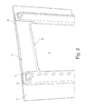
- FIG. 2 goes the hollow profile spar 5 in more detail. As FIG. 2 shows, these bars 5 are provided on both sides of the handle and close the edge of the handle or display opening 3 from, projecting inwardly over the side wall 1 and serve to stabilize the box in the handle or display opening 3 and the handle second
- the limitation of a handle by means of inwardly projecting hollow profile struts is not mandatory, but very often also inwardly or outwardly projecting ribs are used as limitations of the handle and the display opening, wherein the display opening 3 may be formed as a simple handle opening and then down a box side wall continues.
- the ribs are usually again provided from the bottom to the upper edge to stabilize the side wall of the box, but this is not to be understood as limiting, the ribs may extend over portions or a portion of the box sidewall outside or inside ,
- the gas injection opening is then preferably provided at the lower or upper region of the handle in overlap with the handle laterally of the handle.
- the handles are also bounded laterally by an inwardly or outwardly projecting shoulder, with such an embodiment, the gas injection opening is again provided as in the case of the above-described rib structure in turn laterally on the handle in overlap with the handle.
- the gas injection opening would then be provided on this side surface of the shoulder.
Landscapes
- Engineering & Computer Science (AREA)
- Ceramic Engineering (AREA)
- Mechanical Engineering (AREA)
- Details Of Rigid Or Semi-Rigid Containers (AREA)
- Containers Having Bodies Formed In One Piece (AREA)
Abstract
Description
- Die Erfindung betrifft einen Behälter aus Kunststoff, insbesondere Flaschenkasten gemäß dem Oberbegriff des Patentanspruches 1 sowie ein Verfahren zur Herstellung eines solchen Behälters.
- Derartige Kunststoffbehälter, insbesondere Flaschenkasten werden zumeist durch Spritzgießen gebildet, wozu entsprechende Formwerkzeuge mit einem das Negativ des zu formenden Kastens aufweisenden Formhohlraum verwendet werden, in welche heiße Kunststoffschmelze eingespritzt wird. Hierbei erfolgt die Hohlraumausbildung eines Handgriffs häufig durch Gaseinblasung über eine Nadel, wobei das Gas zumeist vom unteren oder inneren Rand des Handgriffes, d.h. des zu formenden Handgriffs, her über Kanäle im Werkzeug eingeblasen wird. Die Nadel steht dabei in der Schmelze, und somit in der Kontur des Handgriffs. Hierbei verbleibt aber nach Herstellung des Kastens die Gaseinblasöffnung, die bei Tragen des Handgriffs fühlbar ist, was nachteilhaft ist. Zudem kann über die Öffnung Reinigungswasser während des periodisch stattfindenden Reinigungsvorgangs derartiger Kasten eindringen, was wiederum nachteilhaft ist, insbesondere auch aus hygienischen Gesichtspunkten. Deswegen wird häufig eine solche Gaseinblasöffnung in einem abschließenden zusätzlichen Arbeitsvorgang verschlossen. Zusätzliche Arbeitsvorgänge verlangsamen aber die Herstellung und führen zu einer Verteuerung.
- Aufgabe der Erfindung ist es, einen entsprechenden Behälter, insbesondere Flaschenkasten zu schaffen, der frei von den beschriebenen Nachteilen des Standes der Technik ist.
- Diese Aufgabe wird erfindungsgemäß für den Behälter durch die im kennzeichnenden Teil des Anspruches 1 enthaltenen Merkmale gelöst sowie für das Verfahren durch die im Anspruch 2 angegebenen Merkmale, wobei zweckmäßige Weiterbildungen sich aus den Unteransprüchen ergeben.
- Nach Maßgabe der Erfindung erfolgt die Hohlraumausbildung eines Handgriffs durch Gaseinblasung, jedoch nunmehr von der Seite des Handgriffes her, d.h. von einer Seite des Handgriffs oder bedarfsweise auch von beiden Seiten her. Das Einblasen des Gases erfolgt nicht mehr mittels einer Nadel die in die Schmelze eintaucht, sondern vorzugsweise über eine Öffnung oder Mündung welche bündig mit der Kontur abschließt. In einigen Fällen kann diese Mündung zweckmäßigerweise auch etwas überstehend oder zurückgesetzt sein. Dadurch ist ein Verschließen der Öffnung automatisch gegeben, da nichts mehr in die Kontur steht. Die Öffnung schließt selbsttätig, aber ohne zusätzlichen Arbeitsschritt. Hierbei sind zur Stabilität die Handgriffe häufig beidseits durch hohle und vom oberen Kastenrand nach unten verlaufende Profilholme verstärkt, die sich in der Regel in das Kasteninnere von der Innenseite der Seitenwandfläche her erstrecken und durch Formschwerter hergestellt sind. Alternativ kann der Handgriff auch einseitig oder beidseitig mit nach innen oder nach außen vorstehenden Rippen begrenzt sein oder über eine seitliche vorspringende Schulter, die wiederum nach außen oder nach innen vorspringen kann. In diesen Fällen erfolgt die Gaseinblasung von der Seite des Handgriffs her über die am Handgriff seitlich anschließende Wandfläche her, was bei Hohlprofilholmen den Vorteil hat, dass die Gaseinblasöffnung nach außen hin versteckt ist, da diese im Inneren des Hohlraums des Profilholms liegt. In der gleichen Weise erfolgt die Gaseinblasung im Falle einer den Handgriff begrenzenden Rippe oder Schulter.
- Nachfolgend wir ein bevorzugtes Ausführungsbeispiel der Erfindung anhand der Zeichnung beschrieben. Darin zeigen
- Fig.1
- eine Teilansicht einer Seitenwand eines Flaschenkastens mit einem Handgriff, der beidseitig von vertikalen Hohlprofilholmen begrenzt ist, von denen beide Holme nur angedeutet sind,
- Fig. 2
- eine Ansicht entsprechend
Figur 1 , jedoch mit beidseitig dargestellten und mit der Seitenwand einstückig spritzgegossenen Holmen sowie - Fig. 3
- eine Teilansicht des Handgriffs von
Fig. 2 mit seitlichem Profilholm zur Darstellung der Hohlausbildung des Handgriffes. -
Figur 1 zeigt in Teilansicht eine Seitenwand eines Flaschenkastens, von innen her gesehen, der in der üblichen Weise aus einem Kastenboden und daran einstückig ausgebildeten umlaufenden vier Seitenwänden ausgebildet ist und quadratischen oder rechteckförmigen, aber auch anderen Grundriss aufweist. Derartige Kästen haben in mindestens einer Seitenwand oder mehreren Seitenwänden Griffe, die zumeist durch Handgriffe am oberen Kastenrand gebildet sind. -
Figur 1 zeigt eine allgemein mit 1 bezeichnete Seitenwand mit einem Handgriff 2 oberhalb einer Displayöffnung oder Handgrifföffnung 3 und einem beidseitg am Handgriff angrenzenden, inFigur 1 nur angedeuteten hohlen vertikalen Holm 5, der sich vom Kastenboden im Wesentlichen bis zum oberen Kastenrand erstreckt. Derartige Holme 5 sind beidseitig des Handgriffs in der Regel vorgesehen, wie insbesondere ausFigur 2 hervorgeht. - Die Profilholme 5 nach
Figur 1 sind in an sich bekannter Weise durch Formschwerter gebildet, die sich in den Spritzgusshohlraum des Werkzeugs erstrecken und nach Formung des Flaschenkastens aus dem Formhohlraum herausgezogen werden, so dass die hohle Ausbildung eines Profilholms entsteht. - Der in
Figur 1 dargestellte Handgriff des Flaschenkastens 2 ist, wie sich insbesondere ausFigur 3 ergibt, als Hohlraum ausgebildet. Eine derartige Hohlraumausbildung ist an sich bekannt und die Ausbildung des Hohlraums erfolgt üblicherweise während des Spritzgießens des Flaschenkastens infolge Gaseinblasung in den Handgriff. - Üblicherweise erfolgt die Gaseinblasung hierbei vom unteren Rand 4 insbesondere nahezu mittig des Handgriffs, über eine Gasblaseinöffnung, die hier nicht dargestellt ist. Durch entsprechende Gaseinblasung erfolgt dann die Hohlraumausbildung des Handgriffes 2. Allerdings verbleibt bei dieser Art der Gaseinblasung eine entsprechende Öffnung aufgrund einer Nadel für die Gaseinblasung, die nach Herstellung des Flaschenkastens ersichtlich ist und den Nachteil hat, dass während des Reinigungsvorganges des Flaschenkastens durch Spritzwasser oder im Tauchbecken über die Öffnung Reinigungswasser in den Hohlraum eindringen kann. Dies ist nachteilhaft, da dann später bei der Handhabung des Flaschenkastens Wasser aus der Öffnung heraustropfen kann. Dies ist auch aus hygienischen Gesichtspunkten sehr nachteilhaft.
- Deswegen können diese Gasblaseinöffnungen in einem separaten Arbeitsschritt verschlossen werden, um diesen Nachteil zu beheben, was aber einen zusätzlichen Arbeitsschritt erfordert, der bei der Massenherstellung derartiger Kästen natürlich in die Kosten entsprechend stark eingeht. Außerdem sind die Gasblasöffnungen, selbst wenn sie nachträglich verschlossen werden, häufig durch Tasten fühlbar, was wiederum sehr nachteilhaft während des Handlings des Flaschenkastens ist.
- Nach Maßgabe der Erfindung erfolgt die Gaseinblasung von der Seite des Handgriffs bzw. des Handgriffs her in Überdeckung mit dem Handgriff und zwar gemäß
Figur 1 von der Innenseite des Profilholmes 5 her, der hier etwa dreieckförmigen Grundriss aufweist. InFigur 1 ist diese Öffnung mit 6 bezeichnet und zwar durch strichlierte Linien. Diese Öffnung ist an der Innenwand 7 des Profilholms 5 eingebracht und etwa am unteren Rande des Handgriffs, aber in Überdeckung mit dem Handgriff und führt unmittelbar in Richtung des Handgriffes, so dass durch entsprechende Gaseinblasung im Handgriff 2 ein Hohlraum entsprechendFigur 3 erzeugt wird. Dort ist der Hohlraum mit 8 bezeichnet. - Da der Hohlraum von innen nicht so schnell abkühlt, und in diesem Bereich die Schmelze nur außen am Werkzeug angrenzt und Wärme abgeführt wird, bleibt die Schmelze länger flüssig, und verschließt das Einblasloch selbstständig.
- Dies hat zur Folge, dass sich nach Gaseinblasung die Öffnung 6 von selbst verschließt infolge des noch weichen Kunststoffs, so dass in einem späteren Reinigungsvorgang Reinigungswasser nicht eindringen kann. Zudem ist selbst für den Fall, dass die Öffnung nicht bzw. nicht vollständig verschlossen wird, diese nach außen hin versteckt und wird in der Regel während des Reinigens des Flaschenkastens nicht durch Reinigungswasser gefüllt.
- Aus
Figur 2 geht der hohle Profilholm 5 genauer hervor. WieFigur 2 zeigt, sind diese Holme 5 beidseitig des Handgriffs vorgesehen und schließen randseitig die Handgriff- oder Displayöffnung 3 ab, ragen nach innen über die Seitenwand 1 vor und dienen zur Stabilisierung des Kastens im Bereich der Handgriff oder Displayöffnung 3 und des Handgriffs 2. - Allerdings ist die Begrenzung eines Handgriffs mittels nach innen vorstehenden hohlen Profilholmen nicht zwingend, vielmehr werden sehr häufig auch nach innen oder nach außen vorspringende Rippen als Begrenzungen des Handgriffs und der Displayöffnung verwendet, wobei die Displayöffnung 3 auch als einfache Grifföffnung ausgebildet sein kann und sich dann nach unten hin eine Kastenseitenwand fortsetzt. Die Rippen sind hierbei zumeist wiederum vom Boden her bis zum oberen Rand vorgesehen, um die Seitenwand des Kastens zu stabilisieren, was aber auch nicht als einschränkend zu verstehen ist, die Rippen können sich auch über Teilbereiche bzw. einen Teilbereich der Kastenseitenwand außen oder innen erstrecken. Auch hier ist dann in Überlappung mit dem Handgriff seitlich des Handgriffs die Gaseinblasöffnung vorzugsweise am unteren oder oberen Bereich des Handgriffes vorgesehen. Häufig sind die Handgriffe auch durch eine nach innen oder nach außen vorstehende Schulter seitlich begrenzt, wobei bei einer solchen Ausführung die Gaseinblasöffnung ebenso wie im Falle der zuvor beschriebenen Rippenstruktur wiederum seitlich am Handgriff in Überlappung mit dem Handgriff vorgesehen ist. In der
Figur 2 wie auch in derFigur 3 sieht man beispielsweise eine entsprechende nach innen vorstehende Schulter im oberen Eckbereich, die hier mit dem Bezugszeichen 8 keine Benennung vorhanden versehen ist und sich für den Fall, dass die Holme 5 nicht vorgesehen sind, seitlich über die Höhe des Handgriffs erstreckt. Für diesen Fall würde dann an dieser Seitenfläche der Schulter die Gaseinblasöffnung vorgesehen sein. - Die Herstellung derartiger Kästen erfolgt durch Spritzgießen aus Kunststoff in einen Formhohlraum, in den im Falle der Ausbildung der Profilholme entsprechende Formschwerter hineintauchen, um die Holme auszubilden. Zumeist vom Boden her, oftmals aber auch von verschiedenen Stellen her, erfolgt das Einspritzen von Kunststoff und zwar Kunststoffschmelze zur Herstellung des Flaschenkastens.
- Infolge des im Bereich der Gaseinblasöffnung noch heißen Kunststoffs erfolgt nach Gaseinspritzung und Formung des Griffhohlraums ein selbsttätiges Verschließen der Gaseinblasöffnung, die im Übrigen ohnedies im Falle eines Handgriffs innerhalb des Handgriffs versteckt ist. Selbst für den Fall, dass die Gaseinblasöffnung also nicht geschlossen wird, würde ein Zutritt von Reinigungswasser während des Reinigungsvorgangs in den Handgriff verringert werden. Eine verbleibende Gaseinblasöffnung wäre damit entsprechend versteckt und würde im Übrigen beim Tragen des Handgriffs auch nicht gefühlt werden können.
Claims (4)
- Behälter aus Kunststoff, insbesondere Flaschenkasten, mit einem Boden und mit vorzugsweise vier umlaufend angeordneten Seitenwänden, wobei in mindestens einer Seitenwand ein Griff ausgebildet ist, der durch einen quer zu den durch benachbarte Seitenwände gebildete, vom Boden zum oberen Behälterrand verlaufende Ecken gerichteten Handgriff gebildet ist, der zumindest an einer Seite, vorzugsweise beidseitig durch einen hohlen Profilholm, eine von der Seitenwand vorstehende Begrenzungsrippe oder eine am Handgriffende vorgesehene Schulter begrenzt ist bzw. sind, welche jeweils eine den Handgriff seitlich begrenzende Wand bilden bzw. beinhalten,
dadurch gekennzeichnet, dass
in der seitlichen und den Handgriff begrenzenden Wand eine vorzugsweise selbstschließende Gaseinblasöffnung für die Gaseinblasung zur Hohlraumausbildung des Handgriffs vorgesehen ist. - Verfahren zur Herstellung eines Behälters aus Kunststoff, insbesondere Flaschenkasten nach Anspruch 1,
dadurch gekennzeichnet, dass
die Gaseinblasung zur Bildung des Griffhohlraums von mindestens einer Randseite des Handgriffs her erfolgt, sich nach Gaseinblasung die seitlich am Handgriff vorgesehene Gaseinblasöffnung vorzugsweise durch die in diesem Bereich noch heiße Kunststoffschmelze selbsttätig nach Gaseinblasung und Bildung des Formhohlraums des Handgriffes schließt. - Verfahren nach Anspruch 2,
dadurch gekennzeichnet, dass
die Gaseinblasöffnung bzw. die Gaseinblasung vom seitlichen Rand des Handgriffs her in seitlicher Überdeckung des durch Spritzgießen mit dem Behälter geformten Handgriffes angeordnet ist bzw. erfolgt. - Verfahren nach Anspruch 2 oder 3,
dadurch gekennzeichnet, dass
die den Handgriff begrenzenden seitlichen Profilholme durch Formschwerter gebildet sind, welche in den Formhohlraum für das Spritzgießen des Kunststoffs vorstehen.
Applications Claiming Priority (1)
| Application Number | Priority Date | Filing Date | Title |
|---|---|---|---|
| DE201010013704 DE102010013704A1 (de) | 2010-04-01 | 2010-04-01 | Behälter aus Kunststoff, insbesondere Flaschenkasten mit einem hohl ausgebildeten Handgriff sowie Verfahren zur Herstellung |
Publications (2)
| Publication Number | Publication Date |
|---|---|
| EP2371721A1 true EP2371721A1 (de) | 2011-10-05 |
| EP2371721B1 EP2371721B1 (de) | 2016-04-13 |
Family
ID=44083484
Family Applications (1)
| Application Number | Title | Priority Date | Filing Date |
|---|---|---|---|
| EP11153200.8A Not-in-force EP2371721B1 (de) | 2010-04-01 | 2011-02-03 | Behälter aus Kunststoff, insbesondere Flaschenkasten mit einem hohl ausgebildeten Handgriff sowie Verfahren zur Herstellung |
Country Status (3)
| Country | Link |
|---|---|
| EP (1) | EP2371721B1 (de) |
| DE (1) | DE102010013704A1 (de) |
| PL (1) | PL2371721T3 (de) |
Citations (4)
| Publication number | Priority date | Publication date | Assignee | Title |
|---|---|---|---|---|
| WO1990005676A2 (de) * | 1988-11-08 | 1990-05-31 | Schoeller International Engineering Kg | Flaschenkasten aus kunststoff |
| DE9012845U1 (de) * | 1989-09-11 | 1990-10-25 | Wavin B.V., Zwolle | Flaschenkasten |
| NL8903105A (nl) * | 1989-12-19 | 1991-07-16 | Wavin Bv | Kunststofkrat met holle kolommen voorzien van een gasinjektieopening, alsmede werkwijze en inrichting voor het vervaardigen van een dergelijke kunststofkrat. |
| DE10016973A1 (de) * | 2000-04-06 | 2001-10-11 | Oberland Engineering Gmbh | Verfahren zum Herstellen eines Handgriffs, danach hergestellte Handgriffe und Flaschenkasten mit einem Handgriff |
-
2010
- 2010-04-01 DE DE201010013704 patent/DE102010013704A1/de not_active Ceased
-
2011
- 2011-02-03 EP EP11153200.8A patent/EP2371721B1/de not_active Not-in-force
- 2011-02-03 PL PL11153200.8T patent/PL2371721T3/pl unknown
Patent Citations (4)
| Publication number | Priority date | Publication date | Assignee | Title |
|---|---|---|---|---|
| WO1990005676A2 (de) * | 1988-11-08 | 1990-05-31 | Schoeller International Engineering Kg | Flaschenkasten aus kunststoff |
| DE9012845U1 (de) * | 1989-09-11 | 1990-10-25 | Wavin B.V., Zwolle | Flaschenkasten |
| NL8903105A (nl) * | 1989-12-19 | 1991-07-16 | Wavin Bv | Kunststofkrat met holle kolommen voorzien van een gasinjektieopening, alsmede werkwijze en inrichting voor het vervaardigen van een dergelijke kunststofkrat. |
| DE10016973A1 (de) * | 2000-04-06 | 2001-10-11 | Oberland Engineering Gmbh | Verfahren zum Herstellen eines Handgriffs, danach hergestellte Handgriffe und Flaschenkasten mit einem Handgriff |
Also Published As
| Publication number | Publication date |
|---|---|
| DE102010013704A1 (de) | 2011-10-06 |
| EP2371721B1 (de) | 2016-04-13 |
| PL2371721T3 (pl) | 2016-10-31 |
Similar Documents
| Publication | Publication Date | Title |
|---|---|---|
| EP2829484B1 (de) | Flaschenkasten mit höhenverstellbarem fachwerkeinsatz | |
| EP2829485A1 (de) | Flaschenkasten mit höhenverstellbarem Fachwerkeinsatz | |
| DE1586881A1 (de) | Milchkasten | |
| DE1479693A1 (de) | Behaelter sowie Verfahren und Vorrichtung zu dessen Herstellung | |
| DE20313077U1 (de) | Transportkasten aus Kunststoff | |
| EP2783999B1 (de) | Teilbarer Behälter, insbesondere Flaschenkasten | |
| DE60305838T2 (de) | Spritzgiessverfahren zum Herstellen eines Kunststoffbehälters oder Kunststoffverschlusses mit unten umgebördeltem Öffnungsrand | |
| DE8915831U1 (de) | Flaschenkasten aus Kunststoff | |
| EP2371721B1 (de) | Behälter aus Kunststoff, insbesondere Flaschenkasten mit einem hohl ausgebildeten Handgriff sowie Verfahren zur Herstellung | |
| WO2022003467A1 (de) | Kunststoffbehälter mit verstärkten eckpartien | |
| EP0231008B1 (de) | Stapelbarer Kasten aus Kunststoff | |
| DE3900894A1 (de) | Verfahren zur herstellung von flaschenkaesten mit waagrechten griffholmen sowie entsprechende flaschenkaesten | |
| EP0586822A2 (de) | Transportkasten aus Kunststoff | |
| EP2383190B1 (de) | Transportbehälter zur Aufnahme von insbesondere Lebensmitteln | |
| EP3218278B1 (de) | Behälter mit lüftungskanal | |
| DE10038386C2 (de) | Kunststoffbehälter sowie Verfahren und Vorrichtung zu seiner Herstellung | |
| DE1486673C (de) | ||
| DE102019129077A1 (de) | Flaschenkasten mit einer Schutzeinrichtung gegen einfallendes Licht, UV-Strahlen und dergleichen | |
| DE102015016276A1 (de) | Kasten aus Kunststoff für die Aufnahme von Flaschen und dgl. | |
| DE102015102307A1 (de) | Kasten aus Kunststoff, insbesondere Flaschenkasten | |
| WO2025108845A1 (de) | Behälter, behälteranordnung sowie verfahren zum herstellen eines behälters | |
| DE1486673B2 (de) | Transportkasten | |
| DE29716383U1 (de) | Flaschenkasten | |
| DE202018105911U1 (de) | Stapelbarer Behälter | |
| EP3428082B1 (de) | Flaschenkasten für die einstellung von sowohl einzelflaschen wie auch mehrflaschenpacks und dergleichen flaschengebinden |
Legal Events
| Date | Code | Title | Description |
|---|---|---|---|
| PUAI | Public reference made under article 153(3) epc to a published international application that has entered the european phase |
Free format text: ORIGINAL CODE: 0009012 |
|
| 17P | Request for examination filed |
Effective date: 20110722 |
|
| AK | Designated contracting states |
Kind code of ref document: A1 Designated state(s): AL AT BE BG CH CY CZ DE DK EE ES FI FR GB GR HR HU IE IS IT LI LT LU LV MC MK MT NL NO PL PT RO RS SE SI SK SM TR |
|
| AX | Request for extension of the european patent |
Extension state: BA ME |
|
| 17Q | First examination report despatched |
Effective date: 20130624 |
|
| RAP1 | Party data changed (applicant data changed or rights of an application transferred) |
Owner name: SCHOELLER ALLIBERT GMBH |
|
| GRAP | Despatch of communication of intention to grant a patent |
Free format text: ORIGINAL CODE: EPIDOSNIGR1 |
|
| INTG | Intention to grant announced |
Effective date: 20150917 |
|
| GRAS | Grant fee paid |
Free format text: ORIGINAL CODE: EPIDOSNIGR3 |
|
| GRAA | (expected) grant |
Free format text: ORIGINAL CODE: 0009210 |
|
| AK | Designated contracting states |
Kind code of ref document: B1 Designated state(s): AL AT BE BG CH CY CZ DE DK EE ES FI FR GB GR HR HU IE IS IT LI LT LU LV MC MK MT NL NO PL PT RO RS SE SI SK SM TR |
|
| REG | Reference to a national code |
Ref country code: GB Ref legal event code: FG4D Free format text: NOT ENGLISH |
|
| REG | Reference to a national code |
Ref country code: AT Ref legal event code: REF Ref document number: 789835 Country of ref document: AT Kind code of ref document: T Effective date: 20160415 Ref country code: CH Ref legal event code: EP |
|
| REG | Reference to a national code |
Ref country code: IE Ref legal event code: FG4D Free format text: LANGUAGE OF EP DOCUMENT: GERMAN |
|
| REG | Reference to a national code |
Ref country code: DE Ref legal event code: R096 Ref document number: 502011009399 Country of ref document: DE |
|
| REG | Reference to a national code |
Ref country code: NL Ref legal event code: FP |
|
| REG | Reference to a national code |
Ref country code: LT Ref legal event code: MG4D |
|
| PG25 | Lapsed in a contracting state [announced via postgrant information from national office to epo] |
Ref country code: FI Free format text: LAPSE BECAUSE OF FAILURE TO SUBMIT A TRANSLATION OF THE DESCRIPTION OR TO PAY THE FEE WITHIN THE PRESCRIBED TIME-LIMIT Effective date: 20160413 Ref country code: LT Free format text: LAPSE BECAUSE OF FAILURE TO SUBMIT A TRANSLATION OF THE DESCRIPTION OR TO PAY THE FEE WITHIN THE PRESCRIBED TIME-LIMIT Effective date: 20160413 Ref country code: NO Free format text: LAPSE BECAUSE OF FAILURE TO SUBMIT A TRANSLATION OF THE DESCRIPTION OR TO PAY THE FEE WITHIN THE PRESCRIBED TIME-LIMIT Effective date: 20160713 |
|
| PG25 | Lapsed in a contracting state [announced via postgrant information from national office to epo] |
Ref country code: RS Free format text: LAPSE BECAUSE OF FAILURE TO SUBMIT A TRANSLATION OF THE DESCRIPTION OR TO PAY THE FEE WITHIN THE PRESCRIBED TIME-LIMIT Effective date: 20160413 Ref country code: PT Free format text: LAPSE BECAUSE OF FAILURE TO SUBMIT A TRANSLATION OF THE DESCRIPTION OR TO PAY THE FEE WITHIN THE PRESCRIBED TIME-LIMIT Effective date: 20160816 Ref country code: GR Free format text: LAPSE BECAUSE OF FAILURE TO SUBMIT A TRANSLATION OF THE DESCRIPTION OR TO PAY THE FEE WITHIN THE PRESCRIBED TIME-LIMIT Effective date: 20160714 Ref country code: LV Free format text: LAPSE BECAUSE OF FAILURE TO SUBMIT A TRANSLATION OF THE DESCRIPTION OR TO PAY THE FEE WITHIN THE PRESCRIBED TIME-LIMIT Effective date: 20160413 Ref country code: SE Free format text: LAPSE BECAUSE OF FAILURE TO SUBMIT A TRANSLATION OF THE DESCRIPTION OR TO PAY THE FEE WITHIN THE PRESCRIBED TIME-LIMIT Effective date: 20160413 Ref country code: ES Free format text: LAPSE BECAUSE OF FAILURE TO SUBMIT A TRANSLATION OF THE DESCRIPTION OR TO PAY THE FEE WITHIN THE PRESCRIBED TIME-LIMIT Effective date: 20160413 Ref country code: HR Free format text: LAPSE BECAUSE OF FAILURE TO SUBMIT A TRANSLATION OF THE DESCRIPTION OR TO PAY THE FEE WITHIN THE PRESCRIBED TIME-LIMIT Effective date: 20160413 |
|
| PG25 | Lapsed in a contracting state [announced via postgrant information from national office to epo] |
Ref country code: IT Free format text: LAPSE BECAUSE OF FAILURE TO SUBMIT A TRANSLATION OF THE DESCRIPTION OR TO PAY THE FEE WITHIN THE PRESCRIBED TIME-LIMIT Effective date: 20160413 |
|
| REG | Reference to a national code |
Ref country code: DE Ref legal event code: R097 Ref document number: 502011009399 Country of ref document: DE |
|
| PG25 | Lapsed in a contracting state [announced via postgrant information from national office to epo] |
Ref country code: RO Free format text: LAPSE BECAUSE OF FAILURE TO SUBMIT A TRANSLATION OF THE DESCRIPTION OR TO PAY THE FEE WITHIN THE PRESCRIBED TIME-LIMIT Effective date: 20160413 Ref country code: SK Free format text: LAPSE BECAUSE OF FAILURE TO SUBMIT A TRANSLATION OF THE DESCRIPTION OR TO PAY THE FEE WITHIN THE PRESCRIBED TIME-LIMIT Effective date: 20160413 Ref country code: DK Free format text: LAPSE BECAUSE OF FAILURE TO SUBMIT A TRANSLATION OF THE DESCRIPTION OR TO PAY THE FEE WITHIN THE PRESCRIBED TIME-LIMIT Effective date: 20160413 Ref country code: EE Free format text: LAPSE BECAUSE OF FAILURE TO SUBMIT A TRANSLATION OF THE DESCRIPTION OR TO PAY THE FEE WITHIN THE PRESCRIBED TIME-LIMIT Effective date: 20160413 |
|
| PLBE | No opposition filed within time limit |
Free format text: ORIGINAL CODE: 0009261 |
|
| STAA | Information on the status of an ep patent application or granted ep patent |
Free format text: STATUS: NO OPPOSITION FILED WITHIN TIME LIMIT |
|
| PG25 | Lapsed in a contracting state [announced via postgrant information from national office to epo] |
Ref country code: SM Free format text: LAPSE BECAUSE OF FAILURE TO SUBMIT A TRANSLATION OF THE DESCRIPTION OR TO PAY THE FEE WITHIN THE PRESCRIBED TIME-LIMIT Effective date: 20160413 |
|
| 26N | No opposition filed |
Effective date: 20170116 |
|
| PG25 | Lapsed in a contracting state [announced via postgrant information from national office to epo] |
Ref country code: SI Free format text: LAPSE BECAUSE OF FAILURE TO SUBMIT A TRANSLATION OF THE DESCRIPTION OR TO PAY THE FEE WITHIN THE PRESCRIBED TIME-LIMIT Effective date: 20160413 |
|
| PG25 | Lapsed in a contracting state [announced via postgrant information from national office to epo] |
Ref country code: MC Free format text: LAPSE BECAUSE OF FAILURE TO SUBMIT A TRANSLATION OF THE DESCRIPTION OR TO PAY THE FEE WITHIN THE PRESCRIBED TIME-LIMIT Effective date: 20160413 |
|
| REG | Reference to a national code |
Ref country code: CH Ref legal event code: PL |
|
| GBPC | Gb: european patent ceased through non-payment of renewal fee |
Effective date: 20170203 |
|
| PG25 | Lapsed in a contracting state [announced via postgrant information from national office to epo] |
Ref country code: LI Free format text: LAPSE BECAUSE OF NON-PAYMENT OF DUE FEES Effective date: 20170228 Ref country code: CH Free format text: LAPSE BECAUSE OF NON-PAYMENT OF DUE FEES Effective date: 20170228 |
|
| REG | Reference to a national code |
Ref country code: IE Ref legal event code: MM4A |
|
| REG | Reference to a national code |
Ref country code: FR Ref legal event code: ST Effective date: 20171031 |
|
| PG25 | Lapsed in a contracting state [announced via postgrant information from national office to epo] |
Ref country code: LU Free format text: LAPSE BECAUSE OF NON-PAYMENT OF DUE FEES Effective date: 20170203 |
|
| PG25 | Lapsed in a contracting state [announced via postgrant information from national office to epo] |
Ref country code: FR Free format text: LAPSE BECAUSE OF NON-PAYMENT OF DUE FEES Effective date: 20170228 |
|
| PG25 | Lapsed in a contracting state [announced via postgrant information from national office to epo] |
Ref country code: IE Free format text: LAPSE BECAUSE OF NON-PAYMENT OF DUE FEES Effective date: 20170203 Ref country code: GB Free format text: LAPSE BECAUSE OF NON-PAYMENT OF DUE FEES Effective date: 20170203 |
|
| PG25 | Lapsed in a contracting state [announced via postgrant information from national office to epo] |
Ref country code: MT Free format text: LAPSE BECAUSE OF FAILURE TO SUBMIT A TRANSLATION OF THE DESCRIPTION OR TO PAY THE FEE WITHIN THE PRESCRIBED TIME-LIMIT Effective date: 20160413 |
|
| PG25 | Lapsed in a contracting state [announced via postgrant information from national office to epo] |
Ref country code: AL Free format text: LAPSE BECAUSE OF FAILURE TO SUBMIT A TRANSLATION OF THE DESCRIPTION OR TO PAY THE FEE WITHIN THE PRESCRIBED TIME-LIMIT Effective date: 20160413 |
|
| PGFP | Annual fee paid to national office [announced via postgrant information from national office to epo] |
Ref country code: NL Payment date: 20190219 Year of fee payment: 9 |
|
| PGFP | Annual fee paid to national office [announced via postgrant information from national office to epo] |
Ref country code: CZ Payment date: 20190129 Year of fee payment: 9 Ref country code: PL Payment date: 20190124 Year of fee payment: 9 |
|
| PGFP | Annual fee paid to national office [announced via postgrant information from national office to epo] |
Ref country code: AT Payment date: 20190215 Year of fee payment: 9 Ref country code: BE Payment date: 20190219 Year of fee payment: 9 |
|
| PG25 | Lapsed in a contracting state [announced via postgrant information from national office to epo] |
Ref country code: HU Free format text: LAPSE BECAUSE OF FAILURE TO SUBMIT A TRANSLATION OF THE DESCRIPTION OR TO PAY THE FEE WITHIN THE PRESCRIBED TIME-LIMIT; INVALID AB INITIO Effective date: 20110203 |
|
| PG25 | Lapsed in a contracting state [announced via postgrant information from national office to epo] |
Ref country code: BG Free format text: LAPSE BECAUSE OF FAILURE TO SUBMIT A TRANSLATION OF THE DESCRIPTION OR TO PAY THE FEE WITHIN THE PRESCRIBED TIME-LIMIT Effective date: 20160413 |
|
| PG25 | Lapsed in a contracting state [announced via postgrant information from national office to epo] |
Ref country code: CY Free format text: LAPSE BECAUSE OF NON-PAYMENT OF DUE FEES Effective date: 20160413 |
|
| PG25 | Lapsed in a contracting state [announced via postgrant information from national office to epo] |
Ref country code: MK Free format text: LAPSE BECAUSE OF FAILURE TO SUBMIT A TRANSLATION OF THE DESCRIPTION OR TO PAY THE FEE WITHIN THE PRESCRIBED TIME-LIMIT Effective date: 20160413 |
|
| PG25 | Lapsed in a contracting state [announced via postgrant information from national office to epo] |
Ref country code: TR Free format text: LAPSE BECAUSE OF FAILURE TO SUBMIT A TRANSLATION OF THE DESCRIPTION OR TO PAY THE FEE WITHIN THE PRESCRIBED TIME-LIMIT Effective date: 20160413 |
|
| PG25 | Lapsed in a contracting state [announced via postgrant information from national office to epo] |
Ref country code: IS Free format text: LAPSE BECAUSE OF FAILURE TO SUBMIT A TRANSLATION OF THE DESCRIPTION OR TO PAY THE FEE WITHIN THE PRESCRIBED TIME-LIMIT Effective date: 20160813 |
|
| PGFP | Annual fee paid to national office [announced via postgrant information from national office to epo] |
Ref country code: DE Payment date: 20200429 Year of fee payment: 10 |
|
| REG | Reference to a national code |
Ref country code: NL Ref legal event code: MM Effective date: 20200301 |
|
| REG | Reference to a national code |
Ref country code: AT Ref legal event code: MM01 Ref document number: 789835 Country of ref document: AT Kind code of ref document: T Effective date: 20200203 |
|
| REG | Reference to a national code |
Ref country code: BE Ref legal event code: MM Effective date: 20200229 |
|
| PG25 | Lapsed in a contracting state [announced via postgrant information from national office to epo] |
Ref country code: CZ Free format text: LAPSE BECAUSE OF NON-PAYMENT OF DUE FEES Effective date: 20200203 |
|
| PG25 | Lapsed in a contracting state [announced via postgrant information from national office to epo] |
Ref country code: AT Free format text: LAPSE BECAUSE OF NON-PAYMENT OF DUE FEES Effective date: 20200203 |
|
| PG25 | Lapsed in a contracting state [announced via postgrant information from national office to epo] |
Ref country code: NL Free format text: LAPSE BECAUSE OF NON-PAYMENT OF DUE FEES Effective date: 20200301 |
|
| PG25 | Lapsed in a contracting state [announced via postgrant information from national office to epo] |
Ref country code: BE Free format text: LAPSE BECAUSE OF NON-PAYMENT OF DUE FEES Effective date: 20200229 |
|
| REG | Reference to a national code |
Ref country code: DE Ref legal event code: R119 Ref document number: 502011009399 Country of ref document: DE |
|
| PG25 | Lapsed in a contracting state [announced via postgrant information from national office to epo] |
Ref country code: DE Free format text: LAPSE BECAUSE OF NON-PAYMENT OF DUE FEES Effective date: 20210901 |
|
| PG25 | Lapsed in a contracting state [announced via postgrant information from national office to epo] |
Ref country code: PL Free format text: LAPSE BECAUSE OF NON-PAYMENT OF DUE FEES Effective date: 20200203 |