EP2370980B1 - Elektromagnetische aktuatorvorrichtung - Google Patents
Elektromagnetische aktuatorvorrichtung Download PDFInfo
- Publication number
- EP2370980B1 EP2370980B1 EP09799245A EP09799245A EP2370980B1 EP 2370980 B1 EP2370980 B1 EP 2370980B1 EP 09799245 A EP09799245 A EP 09799245A EP 09799245 A EP09799245 A EP 09799245A EP 2370980 B1 EP2370980 B1 EP 2370980B1
- Authority
- EP
- European Patent Office
- Prior art keywords
- coil
- core unit
- plunger units
- units
- plunger
- Prior art date
- Legal status (The legal status is an assumption and is not a legal conclusion. Google has not performed a legal analysis and makes no representation as to the accuracy of the status listed.)
- Not-in-force
Links
Images
Classifications
-
- H—ELECTRICITY
- H01—ELECTRIC ELEMENTS
- H01F—MAGNETS; INDUCTANCES; TRANSFORMERS; SELECTION OF MATERIALS FOR THEIR MAGNETIC PROPERTIES
- H01F7/00—Magnets
- H01F7/06—Electromagnets; Actuators including electromagnets
- H01F7/08—Electromagnets; Actuators including electromagnets with armatures
- H01F7/16—Rectilinearly-movable armatures
- H01F7/1638—Armatures not entering the winding
- H01F7/1646—Armatures or stationary parts of magnetic circuit having permanent magnet
-
- H—ELECTRICITY
- H01—ELECTRIC ELEMENTS
- H01F—MAGNETS; INDUCTANCES; TRANSFORMERS; SELECTION OF MATERIALS FOR THEIR MAGNETIC PROPERTIES
- H01F7/00—Magnets
- H01F7/06—Electromagnets; Actuators including electromagnets
- H01F7/08—Electromagnets; Actuators including electromagnets with armatures
- H01F7/16—Rectilinearly-movable armatures
- H01F7/1638—Armatures not entering the winding
-
- F—MECHANICAL ENGINEERING; LIGHTING; HEATING; WEAPONS; BLASTING
- F01—MACHINES OR ENGINES IN GENERAL; ENGINE PLANTS IN GENERAL; STEAM ENGINES
- F01L—CYCLICALLY OPERATING VALVES FOR MACHINES OR ENGINES
- F01L13/00—Modifications of valve-gear to facilitate reversing, braking, starting, changing compression ratio, or other specific operations
- F01L13/0015—Modifications of valve-gear to facilitate reversing, braking, starting, changing compression ratio, or other specific operations for optimising engine performances by modifying valve lift according to various working parameters, e.g. rotational speed, load, torque
- F01L13/0036—Modifications of valve-gear to facilitate reversing, braking, starting, changing compression ratio, or other specific operations for optimising engine performances by modifying valve lift according to various working parameters, e.g. rotational speed, load, torque the valves being driven by two or more cams with different shape, size or timing or a single cam profiled in axial and radial direction
- F01L2013/0052—Modifications of valve-gear to facilitate reversing, braking, starting, changing compression ratio, or other specific operations for optimising engine performances by modifying valve lift according to various working parameters, e.g. rotational speed, load, torque the valves being driven by two or more cams with different shape, size or timing or a single cam profiled in axial and radial direction with cams provided on an axially slidable sleeve
-
- F—MECHANICAL ENGINEERING; LIGHTING; HEATING; WEAPONS; BLASTING
- F01—MACHINES OR ENGINES IN GENERAL; ENGINE PLANTS IN GENERAL; STEAM ENGINES
- F01L—CYCLICALLY OPERATING VALVES FOR MACHINES OR ENGINES
- F01L2820/00—Details on specific features characterising valve gear arrangements
- F01L2820/03—Auxiliary actuators
- F01L2820/031—Electromagnets
-
- H—ELECTRICITY
- H01—ELECTRIC ELEMENTS
- H01F—MAGNETS; INDUCTANCES; TRANSFORMERS; SELECTION OF MATERIALS FOR THEIR MAGNETIC PROPERTIES
- H01F7/00—Magnets
- H01F7/06—Electromagnets; Actuators including electromagnets
- H01F7/08—Electromagnets; Actuators including electromagnets with armatures
- H01F7/16—Rectilinearly-movable armatures
- H01F2007/1669—Armatures actuated by current pulse, e.g. bistable actuators
-
- H—ELECTRICITY
- H01—ELECTRIC ELEMENTS
- H01F—MAGNETS; INDUCTANCES; TRANSFORMERS; SELECTION OF MATERIALS FOR THEIR MAGNETIC PROPERTIES
- H01F7/00—Magnets
- H01F7/06—Electromagnets; Actuators including electromagnets
- H01F7/08—Electromagnets; Actuators including electromagnets with armatures
- H01F7/16—Rectilinearly-movable armatures
- H01F2007/1684—Armature position measurement using coils
-
- H—ELECTRICITY
- H01—ELECTRIC ELEMENTS
- H01F—MAGNETS; INDUCTANCES; TRANSFORMERS; SELECTION OF MATERIALS FOR THEIR MAGNETIC PROPERTIES
- H01F7/00—Magnets
- H01F7/06—Electromagnets; Actuators including electromagnets
- H01F7/08—Electromagnets; Actuators including electromagnets with armatures
- H01F7/16—Rectilinearly-movable armatures
- H01F2007/1692—Electromagnets or actuators with two coils
-
- H—ELECTRICITY
- H01—ELECTRIC ELEMENTS
- H01F—MAGNETS; INDUCTANCES; TRANSFORMERS; SELECTION OF MATERIALS FOR THEIR MAGNETIC PROPERTIES
- H01F7/00—Magnets
- H01F7/06—Electromagnets; Actuators including electromagnets
- H01F7/08—Electromagnets; Actuators including electromagnets with armatures
- H01F7/081—Magnetic constructions
Definitions
- the present invention relates to an electromagnetic actuator device according to the preamble of the main claim.
- Such devices are well known in the art, are commonly used as bistable actuators for control purposes on an internal combustion engine, such as for camshaft adjustment, and have two or more ram units which - synchronously same or opposite, or independently Energization of the coil means are moved to perform the intended purpose.
- US 4 779 582 A discloses a device according to the preamble of present claim 1.
- the object of the present invention is therefore to improve a generic electromagnetic actuator device having a core unit having a coil means, which is designed to cooperate with at least two ram units acting on anchor means, that not only a compact arrangement (especially with regard to a minimum achievable distance between two tappet units) is improved, but also such a device is optimized in terms of required components and components as well as in the production cost.
- the core unit is designed such that it can interact with a plurality of spatially spaced ram units, wherein the core unit is assigned a (and preferably only one) coil or coil unit (coil body), then the majority in response to their energization the ram units is moved.
- the core unit in one piece, at least in such a way that a leg region (leg pair region) designed to cooperate with at least two of the tappet units is formed in one piece. It is within the scope of preferred embodiments, the core unit yoke or U-shaped design and provide free end or end surfaces of this configuration for cooperation with the plunger units.
- the geometric realization is limited neither to a two-dimensional structure, nor to the provision of only two free legs: Rather, it is within the scope of preferred further developments of the invention, the core unit multiple U-shaped, E-shaped or H-shaped design, or but to twist individual legs spatially (in a third dimension) so that they are not in any common plane with a connecting portion of the core unit; All these geometric variants can then be based on the respective installation requirements and / or purpose of the electromagnetic actuator device according to the invention, it being particularly advantageous if each leg or each free end face of such a leg then facing a ram unit of the anchor means for cooperation.
- the coil means comprise at least one coil extending around a portion of the core unit; While in principle the position or arrangement of this coil is arbitrary and can be made dependent on magnetic and / or spatial conditions, it is expedient to provide this coil in a central and / or connecting region between free legs of the core unit.
- At least one of the plunger units in particular in the engaging and / or effective range with the core unit, with permanent magnet means to provide so far as to enable the realization of a bistable effect.
- such permanent magnet means form such that the desired (possibly synchronized) movement behavior of the plurality of plunger units can be done in the desired manner: For example, a gleichpolige arrangement of permanent magnet means on opposing ram units with respect to the ends of a U-shaped Core unit lead to an opposite plunger movement when energizing a (single) coil on the core unit; On the other hand, a provision of the permanent magnet units in opposite polarity would allow a rectified movement of the tappet units.
- the device according to the invention is particularly suitable to design the device according to the invention as a bistable actuator, namely to design at least one of the plunger units so that they assume a normally-stable state in both end positions of a movement and switching state.
- the present invention is particularly suitable for limited installation dimensions and environmental conditions such as in the field of motor vehicles and motor vehicle internal combustion engines, but the present invention is not limited to this purpose.
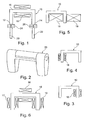
- the core unit 10 is electromagnetically cooperating with a pair of plunger units 20, 22 as anchor means, each aligned axially with associated leg portions of the core unit 10 and axially opposed to the leg ends 12, 14, respectively.
- the plunger units 20 and 22 each have a permanent magnet unit 24 and 26, which, depending on the polarity of the coil unit 16 generated electromagnetic field, attractive or repulsive acts and accordingly the (not shown in detail Way) movably mounted ram unit 20 or 22 moves in the axial direction, in order to fulfill an intended (bistable) setting purpose on the permanent magnet units 24 and 26, respectively, opposite the end of the tappet units 20 and 22, for example the interaction with a suitable actuating partner of a camshaft adjustment of an internal combustion engine or the like.
- a permanent magnet unit 24 and 26 which, depending on the polarity of the coil unit 16 generated electromagnetic field, attractive or repulsive acts and accordingly the (not shown in detail Way) movably mounted ram unit 20 or 22 moves in the axial direction, in order to fulfill an intended (bistable) setting purpose on the permanent magnet units 24 and 26, respectively, opposite the end of the tappet units 20 and 22, for example the interaction with a suitable actuating partner of a camshaft adjustment of an internal combustion engine or the like.
- Fig. 2 can be seen in the physical realization of the illustrated embodiment of the principle Fig. 1 produced in this way a very compact and efficient structure, namely a simple to produce and low component cost requiring bracket structure, which may be provided in a simple manner the respective control partner against suitable.
- this offers in Fig. 1 shown by way of example housing 23, the possibility not only the core and coil unit 10, 18 receive, but also to design a guide for the pair of plunger units.
- the Fig. 3 to 6 illustrate variants of the basic embodiment of the Fig. 1 ; so it is, depending on the positioning ( Fig. 3, 4 ) of the coil unit 18 and / or dimensioning of the coil unit 18 (large winding in FIG Fig. 5 ) possible to suitably influence the course of the field along the core unit or in cooperation with the plurality of ram units, for example in such a way that intentionally force or movement asymmetries are to be generated.
- FIGS. 6 . 7 with a plurality of coils 17, 18, 19 and / or windings (possibly on a common bobbin) offer on the one hand the ability to bring about by superimposing, gegenpoliges or same pole driving the individual coils, targeted field courses to possibly also be able to react situationally.
- a bobbin may be about also circuitry to substitute a reversal in polarity of the coil (for an upstream control device), two windings 18, 18 a carry ( Fig. 7 ), so that then optionally a respective wire pair and consequently only a part of the coil is energized.
- tappet units will induce corresponding voltages in their movement relative to the core unit, for instance with the permanent magnet units provided at the end abut the additional coil for detection and further processing.
- the Fig. 8 shows a further variant;
- the core unit 30 is configured (E-shape with each provided in the intermediate region of the three legs coil units 42, 44) as a total of three the respective leg ends 46, 48, 50 opposite (not shown) plunger can be individually offset in each case in motion, by varying the wiring or energization of the coils 42, 44.
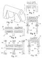
- a core unit 32 can also suitably be provided with legs opposite one another, so that the in Fig. 11 schematically shown double H-shape is formed; only schematically the free legs 46, 48, 50 more free legs 52, 54, 56 are compared;
- permanent magnets corresponding to associated movable plunger units are only schematically provided.
- FIGS. 9, 10 illustrate the desired movement behavior, as the example of FIGS. 9, 10 (according to the basic embodiment of the Fig. 1 ) can be explained:
- the Fig. 9 illustrates how the free legs 12, 14 each opposite in the same direction poled permanent magnets 24 and 26; When schematically indicated by the arrows 60 field profile so arises for the plunger unit 20, the downward, for the plunger unit 22, the upward movement. If, on the other hand, cf. Fig. 10 , the permanent magnet 26 reversed, arises at the same arrow lines 60 a common downward movement.
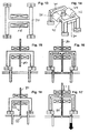
- Fig. 14 shows a cuboid geometry of the plunger units, wherein the respective free legs are connected by connecting element 70, 72 in the manner of a rectangular frame and coil units 74 are then formed on longitudinal portions of the frame. Based on 15 to 18 It will now be described how an additionally inserted flux guide 80 in the manner of a guide disc closes a (permanent) magnetic circuit through the respective permanent magnets, as far as the permanent magnets are decoupled from each other and thus suppresses mutual interference.
- Such flux-conducting elements make it possible, in particular, to drastically reduce the switching cycles of the present invention by decoupling mutual interference.
Landscapes
- Physics & Mathematics (AREA)
- Electromagnetism (AREA)
- Engineering & Computer Science (AREA)
- Power Engineering (AREA)
- Electromagnets (AREA)
- Valve Device For Special Equipments (AREA)
Abstract
Description
- Die vorliegende Erfindung betrifft eine elektromagnetische Aktuatorvorrichtung nach dem Oberbegriff des Hauptanspruchs.
- Derartige Vorrichtungen sind aus dem Stand der Technik allgemein bekannt, werden üblicherweise als bistabile Aktoren für Stellzwecke an einem Verbrennungsmotor, etwa zur Nockenwellenverstellung, verwendet und weisen zwei oder mehr Stößeleinheiten auf, welche -- synchron gleich- oder gegenläufig, oder unabhängig voneinander -- durch Bestromung der Spulenmittel bewegt werden, um den beabsichtigen Stellzweck durchzuführen.
- Gerade jedoch in einem räumlich beengten Einbaukontext eines Verbrennungsmotors kommt es darauf an, eine Aktuatorvorrichtung mit einer Mehrzahl von Stößeleinheiten kompakt auszubilden, wobei bekannte Vorgehensweisen aus dem Stand der Technik, nämlich zwei oder mehr benachbart zueinander angeordnete Einzelaktuatoren mit jeweils einer Kern-, Spulen- und Stößeleinheit häufig nicht geeignet platziert werden können. Die deutsche Patentanmeldung
10 2007 028 600 der Anmelderin beschreibt diesbezüglich einen Ansatz, zueinander benachbarte Einzelaktuatoren möglichst kompakt und platzsparend nebeneinander anzuordnen, auch in der Absicht, einen -- anwendungsbedingten -- Abstand zwischen zwei Stößeleinheiten zu realisieren. - Während auf diese Weise die Kompakteinheit der gattungsbildenden Technologie erhöht werden kann, bleibt -- insbesondere im Hinblick auf Großserien- bzw. Massenfertigungdas inhärente Problem des bauteil- und herstellungsbedingten Aufwandes.
-
US 4 779 582 A offenbart eine Vorrichtung gemäß dem Oberbegriff des vorliegenden Anspruchs 1. - Aufgabe der vorliegenden Erfindung ist es daher, eine gattungsbildende elektromagnetische Aktuatorvorrichtung mit einer Spulenmittel aufweisenden Kerneinheit, die zum Zusammenwirken mit mindestens zwei Stößeleinheiten aufwirkenden Ankermitteln ausgebildet ist, so zu verbessern, dass nicht nur eine kompakte Anordnung (vor allem im Hinblick auf einen minimal erreichbaren Abstand zwischen zwei Stößeleinheiten) verbessert ist, sondern auch eine solche Vorrichtung im Hinblick auf benötigte Bauteile und Komponenten sowie im Herstellungsaufwand optimiert ist.
- Die Aufgabe wird durch die elektromagnetische Aktuatorvorrichtung mit den Merkmalen des Hauptanspruchs gelöst; vorteilhafte Weiterbildungen der Erfindung sind in den Unteransprüchen beschrieben.
- In erfindungsgemäß vorteilhafter Weise ist die Kerneinheit so ausgebildet, dass sie mit einer Mehrzahl von räumlich voneinander beabstandeten Stößeleinheiten zusammenwirken kann, wobei der Kerneinheit eine (und bevorzugt lediglich eine) Spule oder Spuleneinheit (Spulenkörper) zugeordnet ist, als Reaktion auf deren Bestromung dann die Mehrzahl der Stößeleinheiten bewegt wird.
- Im Rahmen einer bevorzugten Weiterbildung liegt es dabei, die Kerneinheit einstückig auszugestalten, zumindest so, dass ein zum Zusammenwirken mit mindestens zwei der Stößeleinheiten ausgebildeter Schenkelbereich (Schenkelpaar-Bereich) einstückig ausgebildet ist. Dabei liegt es im Rahmen bevorzugter Ausführungsformen, die Kerneinheit joch-oder U-förmig auszugestalten und freie Stirn- bzw. Endflächen dieser Ausgestaltung zum Zusammenwirken mit den Stößeleinheiten vorzusehen.
- Dabei ist die geometrische Realisierung weder auf eine zweidimensionale Struktur, noch auf das Vorsehen von lediglich zwei freien Schenkeln beschränkt: Vielmehr liegt es im Umfang bevorzugter weiterer Weiterbildungen der Erfindung, die Kerneinheit mehrfach U-förmig, E-förmig oder H-förmig auszugestalten, oder aber einzelne Schenkel gegeneinander räumlich (in einer dritten Dimension) so zu verdrehen, dass diese in keiner gemeinsamen Ebene mit einem Verbindungsabschnitt der Kerneinheit liegen ; all diese geometrischen Varianten können sich dann nach jeweiligen Einbauvoraussetzungen und/oder Zweckbestimmungen der erfindungsgemäßen elektromagnetischen Aktuatorvorrichtung richten, wobei es besonders günstig ist, wenn jedem Schenkel bzw. jeder freien Stirnfläche eines solchen Schenkels dann eine Stößeleinheit der Ankermittel zum Zusammenwirken gegenübersteht.
- Im Rahmen bevorzugter Weiterbildungen der Erfindung weisen die Spulenmittel mindestens eine sich um einen Abschnitt der Kerneinheit herum erstreckende Spule auf; während prinzipiell die Lage oder Anordnung dieser Spule beliebig ist und von magnetischen und/oder räumlichen Gegebenheiten abhängig gemacht werden kann, bietet es sich weiterbildungsgemäß an, diese Spule in einem zentralen und/oder Verbindungsbereich zwischen freien Schenkeln der Kerneinheit vorzusehen.
- Auch ist es im Rahmen von Weiterbildungen vorteilhaft, mindestens eine der Stößeleinheiten, insbesondere im Eingriffs- und/oder Wirkbereich mit der Kerneinheit, mit Permanentmagnetmitteln zu versehen, um insoweit etwa das Realisieren einer bistabilen Wirkung, zu ermöglichen.
- Zusätzlich weiterbildungsgemäß ist vorgesehen, derartige Permanentmagnetmittel so auszubilden, dass das gewünschte (ggf. synchronisierte) Bewegungsverhalten der Mehrzahl von Stößeleinheiten in der gewünschten Weise erfolgen kann: So würde etwa eine gleichpolige Anordnung von Permanentmagnetmitteln an einander gegenüberliegenden Stößeleinheiten im Hinblick auf Enden einer U-förmigen Kerneinheit zu einer gegenläufigen Stößelbewegung bei Bestromung einer (einzigen) Spule an der Kerneinheit führen; ein gegenpoliges Vorsehen der Permanentmagneteinheiten würde dagegen eine gleichgerichtete Bewegung der Stößeleinheiten ermöglichen.
- Auch ist es im Rahmen von Weiterbildungen der Erfindung möglich und vorgesehen, insbesondere im Fall von Permanentmagneteinheiten aufweisenden Stößeleinheiten zusätzlich die Kerneinheit mit magnetisch wirksamen Flussleitmitteln so zu versehen, dass eine magnetische Entkopplung der Stößeleinheiten voneinander erfolgt, mithin also ein gegenseitiger magnetischer Einfluss verhindert, zumindest vermindert, ist.
- Während es im Rahmen der Erfindung vorteilhaft und günstig ist, die Anzahl benötigter Spulen der Spulenmittel zu minimieren (idealerweise auf eins zu reduzieren), ist die vorliegende Erfindung hierauf nicht beschränkt, vielmehr ist es im Rahmen bevorzugter Weiterbildungen möglich, zusätzliche Spulen und/oder Wicklungen vorzusehen, etwa mit dem Zweck, durch gezieltes Überlagern und/oder Verdrängen von durch die Spule(en) bzw. Wicklung erzeugten Feldern das Bewegungsverhalten der Stößeleinheiten gesamt und relativ zueinander zu beeinflussen, darüber hinaus eignet sich weiterbildungsgemäß etwa eine zusätzliche Wicklung (auf einer bereits vorhandenen Spule bzw. dem zugehörigen Spulenkörper), um etwa durch Induktion erzeugte und detektierbare Bewegungs- und Schaltzustände von Stößeleinheiten zu erfassen und einer weiteren Auswertung zugänglich zu machen.
- Besonders geeignet ist es, die erfindungsgemäße Vorrichtung als bistabilen Aktuator auszugestalten, nämlich zumindest eine der Stößeleinheiten so auszubilden, dass diese in beiden Endstellungen eines Bewegungs- und Schaltzustands einen stromlos stabilen Zustand einnimmt. Damit eignet sich dann die vorliegende Erfindung in besonderer Weise für begrenzte Einbaumaße und Umgebungsbedingungen etwa im Bereich von Kraftfahrzeugen und Kraftfahrzeug-Verbrennungsmotoren, wobei jedoch die vorliegende Erfindung nicht auf diesen Einsatzzweck beschränkt ist.
- Weitere Vorteile, Merkmale und Einzelheiten der Erfindung ergeben sich aus der nachfolgenden Beschreibung bevorzugter Ausführungsbeispiele sowie anhand der Zeichnungen; diese zeigen in
- Fig. 1
- eine schematische Prinzipdarstellung der elektromagnetischen Aktuatorvorrichtung gemäß einer ersten, bevorzugten Ausführungsform der vorliegenden Erfindung;
- Fig. 2
- eine perspektivische Darstellung eines Beispiels zur physischen Realisierung des Ausführungsbeispiels der
Fig. 1 ; - Fig. 3 bis Fig. 5
- verschiedene Varianten zur Platzierung einer einzelnen Spule als Spulenmittel an einer Position der U-förmig geformten Kerneinheit;
- Fig. 6, Fig. 7
- weitere Ausführungsformen als Varianten der Erfindung mit einer Mehrzahl von Spulen an einem U-förmig gebogenen Kernelement;
- Fig. 8
- eine weitere Variante der Erfindung mit einer Mehrzahl von Spulen und E-förmigem Kernelement;
- Fig. 9, Fig. 10
- Schemadarstellungen zum Erläutern des Zusammenwirkens der Vorrichtung gemäß
Fig. 1, Fig. 2 mit an den Stößeleinheiten vorgesehenen Permanentmagneten; - Fig. 11
- eine weitere Variante der vorliegenden Erfindung als Ausführungsform mit Doppel-H-förmiger Kerneinheit;
- Fig. 12 bis Fig. 14
- weitere Varianten der Erfindung mit dreidimensional angeordneten Schenkelenden einer Kerneinheit;
- Fig. 15 bis Fig. 18
- eine weitere Variante der Erfindung mit zwischen einem Paar von an Stößeleinheiten sitzenden Permanentmagneten vorgesehen Flussleitelementen zur Entkopplung des (permanent-)magnetischen Einflusses aufeinander.
- Als Reaktion auf die Bestromung wirkt die kerneinheit 10 elektromagnetisch zusammen mit einem Paar von Stößeleinheiten 20, 22 als Ankermittel, welche jeweils axial zu zugehörigen Schenkelabschnitten der Kerneinheit 10 ausgerichtet sind und den Schenkelenden 12 bzw. 14 axial gegenüberstehen.
- Im auf die Kerneinheit 10 gerichteten Endbereich weisen die Stößeleinheiten 20 bzw. 22 jeweils eine Permanentmagneteinheit 24 bzw. 26 auf, welche, je nach Polarität des durch Bestromung der Spuleneinheit 16 erzeugten elektromagnetischen Feldes, anziehend oder abstoßend wirkt und entsprechend die (in nicht näher gezeigter Weise) bewegbar gelagerte Stößeleinheit 20 bzw. 22 in axialer Richtung bewegt, um an dem Permanentmagneteinheiten 24 bzw. 26 entgegengesetzten Ende der Stößeleinheiten 20 bzw. 22 einen vorgesehenen (bistabilen) Stellzweck zu erfüllen, etwa das Zusammenwirken mit einem geeigneten Stellpartner einer Nockenwellenverstellung eines Verbrennungsmotors o.dgl. Anwendung.
- Wie die
Fig. 2 erkennen lässt, wird in der physischen Realisierung des prinzipiell dargestellten Ausführungsbeispiels derFig. 1 auf diese Weise eine sehr kompakte und effiziente Struktur erzeugt, nämlich eine einfach herzustellende und geringen Bauteileaufwand erfordernde Bügelstruktur, welche in einfacher Weise dem jeweiligen Stellpartner geeignet gegenüber vorgesehen sein kann. Insbesondere bietet das inFig. 1 exemplarisch gezeigte Gehäuse 23 die Möglichkeit, nicht nur die Kern- und Spuleneinheit 10, 18 aufzunehmen, sondern zusätzlich eine Führung für das Paar der Stößeleinheiten auszugestalten. - Die
Fig. 3 bis 6 verdeutlichen Varianten des prinzipiellen Ausführungsbeispiels derFig. 1 ; so ist es, je nach Positionierung (Fig. 3, 4 ) der Spuleneinheit 18 und/oder Dimensionierung der Spuleneinheit 18 (große Wicklung inFig. 5 ) möglich, geeignet den Feldverlauf entlang der Kerneinheit bzw. im Zusammenwirken mit der Mehrzahl der Stößeleinheiten zu beeinflussen, etwa dergestalt, dass gezielt Kraft- bzw. Bewegungsunsymmetrien erzeugt werden sollen. - Die Realisierungen der
Figuren 6 ,7 , mit einer Mehrzahl von Spulen 17, 18, 19 und/oder Wicklungen (ggf. auf einem gemeinsamen Spulenträger) bieten zum einen die Möglichkeit, durch Überlagern, gegenpoliges bzw. gleichpoliges Ansteuern der Einzelspulen, gezielte Feldverläufe herbeizuführen, um möglicherweise auch situativ reagieren zu können. Zusätzlich kann, etwa auch um schaltungstechnisch (für ein vorgeschaltetes Steuergerät) ein Umpolen der Spule zu substituieren, ein Spulenträger zwei Wicklungen 18, 18a tragen (Fig. 7 ), so dass dann wahlweise ein jeweiliges Drahtpaar und mithin nur ein Teil der Spule bestromt wird. Auch ist es möglich, eine zweite, nicht aktiv bestromte Spule oder Wicklung zu benutzen, um Schaltzustände der betreffenden Aktuatorvorrichtung zu detektieren: So werden Stößeleinheiten in ihrer Bewegung relativ zur Kerneinheit, etwa mit den endseitig vorgesehenen Permanentmagneteinheiten, entsprechende Spannungen induzieren, welche dann am Zweipol der zusätzlichen Spule zur Detektion und weiteren Verarbeitung anliegen. - Die
Fig. 8 zeigt eine weitere Variante; hier ist die Kerneinheit 30 so ausgestaltet (E-Form mit jeweils im Zwischenbereich der drei Schenkel vorgesehenen Spuleneinheiten 42, 44) wie insgesamt drei den jeweiligen Schenkelenden 46, 48, 50 gegenüberstehende (nicht gezeigte) Stößel jeweils individuell in Bewegung zueinander versetzt werden können, durch Variieren der Beschaltung bzw. Bestromung der Spulen 42, 44. - Dieses Prinzip scheint nunmehr nahezu beliebig erweiterbar; wie etwa in den
Figuren 11, 12 gezeigt, lässt sich eine Kerneinheit 32 geeignet auch gegenüberliegend mit Schenkeln ausstatten, so dass die inFig. 11 schematisch gezeigte doppelte H-Form entsteht; lediglich schematisch sind den freien Schenkeln 46, 48 , 50 weitere freie Schenkel 52, 54, 56 gegenübergestellt; lediglich schematisch sind auch hier Permanentmagneten entsprechend zugehöriger bewegbarer Stößeleinheiten (nicht gezeigt) vorgesehen. - Je nach Positionierung bzw. Anordnung der Permanentmagneten lässt sich das gewünschte Bewegungsverhalten erzeugen, wie am Beispiel der
Figuren 9, 10 (entsprechend dem prinzipiellen Ausführungsbeispiel derFig. 1 ) erläutert werden kann: DieFig. 9 verdeutlicht, wie den freien Schenkeln 12, 14 jeweils in gleicher Richtung gepolte Permanentmagneten 24 bzw. 26 gegenüberstehen; bei durch die Pfeile 60 schematisch angedeutetem Feldverlauf entsteht so für die Stößeleinheit 20 die abwärts gerichtete, für die Stößeleinheit 22 die aufwärts gerichtete Bewegung. Wird dagegen, vgl.Fig. 10 , der Permanentmagnet 26 umgepolt, entsteht bei gleich verlaufenden Pfeillinien 60 eine gemeinsame Abwärtsbewegung. - Unter Bezug auf die
Figuren 12 bis 14 und die darin skizzierten Ausführungsformen zeigt sich, dass auch eine dreidimensionale Anordnung möglich und von der Erfindung umfasst ist, d.h. jeweilige freie Schenkel müssen nicht miteinander in einer gemeinsamen Ebene liegen (bzw. mit einem Verbindungsabschnitt der Kerneinheit): So verdeutlicht das Ausführungsbeispiel derFig. 12 ,13 , dass rein schematisch die Kerneinheit zwar eine H-Form einnimmt, in der physischen Realisierung (Fig. 12 ) jedoch die freien Schenkel eines Gehäuses 36 zueinander einen spitzen Winkel und keinen 180° Winkel ausbilden. - Die Anordnung der
Fig. 14 zeigt dagegen eine quaderförmige Geometrie der Stößeleinheiten, wobei die jeweiligen freien Schenkel durch Verbindungselement 70, 72 in der Art eines rechteckigen Rahmens verbunden sind und an Längsabschnitten des Rahmens dann Spuleneinheiten 74 ausgebildet sind. Anhand derFig. 15 bis 18 wird nunmehr beschrieben, wie ein zusätzlich eingefügtes Flussleitelement 80 in der Art einer Leitscheibe einen (permanent-)magnetischen Kreis durch die jeweiligen Permanentmagneten schließt, insoweit die Permanentmagneten voneinander entkoppelt und damit eine gegenseitige Beeinflussung unterdrückt. - Sobald, wie in
Fig. 17 gezeigt, eine der Spulen bestromt wird, wird (s. im Bereich rechts) eine Gegenkraft zum permanentmagnetischen Kreis erzeugt, damit das Permanentmagnetfeld geschwächt, neutralisiert oder gar die zugehörige Stößeleinheit abgestoßen. - Derartige Flussleitelemente ermöglichen es, insbesondere die Schalt- bzw. Taktzyklen der vorliegenden Erfindung durch das Entkoppeln bzw. Verhindern eines gegenseitigen Einflusses drastisch zu vermindern.
Claims (10)
- Elektromagnetische Aktuatorvorrichtung mit
einer Spulenmittel (18,18a; 42. 44; 74) aufweisenden Kerneinheit (10; 30; 32), die zum Zusammenwirken mit relativ zur Kerneinheit beweglich geführten Ankermitteln (20, 22) als Reaktion auf eine Bestromung der Spulenmittel ausgebildet ist, wobei
die Kerneinheit zum Zusammenwirken mit einer Mehrzahl von räumlich voneinander beabstandeten Stößeleinheiten (20, 22) der Ankermittel so ausgebildet ist, dass als Reaktion auf das Bestromen einer Spule der Spulenmittel eine elektromagnetische Wechselwirkung mit der Mehrzahl der Stößeleinheiten erfolgt,
dadurch gekennzeichnet, dass
mindestens eine der Stößeleinheiten zum Zusammenwirken mit der Kerneinheit ausgebildete Permanentmagnetmittel (24; 26) aufweist und die Kerneinheit joch- oder U-förmig ausgestaltet und mit freien schenkelseitigen Stirnflächen zum Zusammenwirken mit der Mehrzahl von Stößeleinheiten versehen ist. - Vorrichtung nach Anspruch 1, dadurch gekennzeichnet, dass die Kerneinheit einstückig ausgebildet ist.
- Vorrichtung nach einem der Ansprüche 1 bis 2, dadurch gekennzeichnet, dass die Kerneinheit (30; 32) mehrfach U-förmig, E-förmig oder H-förmig sowie zum Zusammenwirken mit einer freien Schenkeln entsprechenden Mehrzahl von Stößeleinheiten ausgebildet ist.
- Vorrichtung nach einem der Ansprüche 1 bis 3, dadurch gekennzeichnet, dass mindestens zwei freie Schenkel der Kerneinheit sich so erstreckend ausgebildet sind, dass sie nicht in einer gemeinsamen Ebene mit einem Verbindungsabschnitt der Schenkel liegen.
- Vorrichtung nach einem der Ansprüche 1 bis 4, dadurch gekennzeichnet, dass die Spulenmittel mindestens eine sich um einen Abschnitt der Kerneinheit herum erstreckende Spule (18; 18, 18a) aufweisen.
- Vorrichtung nach einem der Ansprüche 1 bis 5, dadurch gekennzeichnet, dass Stößeleinheiten der Ankermittel durch ein gleich- oder gegenpoliges Vorsehen von Permanentmagnetmitteln so ausgebildet sind, dass zwei Stößeleinheiten bei Bestromung einer Spule der Spulenmittel gleich- oder gegenläufig bewegt werden können.
- Vorrichtung nach einem der Ansprüche 1 bis 6, gekennzeichnet durch magnetische Flussleitmittel (80), die so zwischen mindestens zwei der Mehrzahl von Stößeleinheiten vorgesehen sind, dass eine gegenseitige magnetische Beeinflussung der Stößeleinheiten vermindert ist.
- Vorrichtung nach einem der Ansprüche 1 bis 7, dadurch gekennzeichnet, dass die Spulenmittel eine zusätzliche, zur Bewegungs- und/oder Schaltzustandsdetektion mindestens einer der Stößeleinheiten beschaltete Wickelung aufweisen.
- Vorrichtung nach einem der Ansprüche 1 bis 8, die als bistabiler Aktuator so ausgebildet ist, dass mindestens eine der Mehrzahl der Stößeleinheiten in jeweiligen Endpositionen stromlos gehalten ist.
- Vorrichtung nach einem der Ansprüche 1 bis 9, ausgebildet als Stelleinheit für einen Verbrennungsmotor, insbesondere als Stelleinheit zur Nockenwellenverstellung.
Applications Claiming Priority (2)
| Application Number | Priority Date | Filing Date | Title |
|---|---|---|---|
| DE202008015980U DE202008015980U1 (de) | 2008-12-03 | 2008-12-03 | Elektromagnetische Aktuatorvorrichtung |
| PCT/EP2009/008371 WO2010063394A1 (de) | 2008-12-03 | 2009-11-25 | Elektromagnetische aktuatorvorrichtung |
Publications (2)
| Publication Number | Publication Date |
|---|---|
| EP2370980A1 EP2370980A1 (de) | 2011-10-05 |
| EP2370980B1 true EP2370980B1 (de) | 2012-08-15 |
Family
ID=42060715
Family Applications (1)
| Application Number | Title | Priority Date | Filing Date |
|---|---|---|---|
| EP09799245A Not-in-force EP2370980B1 (de) | 2008-12-03 | 2009-11-25 | Elektromagnetische aktuatorvorrichtung |
Country Status (5)
| Country | Link |
|---|---|
| US (1) | US8729992B2 (de) |
| EP (1) | EP2370980B1 (de) |
| CN (1) | CN102239531B (de) |
| DE (1) | DE202008015980U1 (de) |
| WO (1) | WO2010063394A1 (de) |
Families Citing this family (16)
| Publication number | Priority date | Publication date | Assignee | Title |
|---|---|---|---|---|
| DE102009056609A1 (de) * | 2009-12-02 | 2011-06-09 | Schaeffler Technologies Gmbh & Co. Kg | Elektromagnetische Stellvorrichtung |
| DE202010010371U1 (de) * | 2010-07-16 | 2011-10-17 | Eto Magnetic Gmbh | Elektromagnetische Stellvorrichtung |
| DE202011004021U1 (de) * | 2011-03-16 | 2012-07-09 | Eto Magnetic Gmbh | Elektromagnetische Aktuatorvorrichtung |
| DE102011050730A1 (de) | 2011-05-30 | 2012-12-06 | Eto Magnetic Gmbh | Nockenwellenverstellvorrichtung |
| DE102012103796A1 (de) * | 2012-04-30 | 2013-10-31 | Eto Magnetic Gmbh | Elektromagnetische Stellvorrichtung |
| DE102012107922A1 (de) * | 2012-08-28 | 2014-03-06 | Eto Magnetic Gmbh | Elektromagnetische Aktuatorvorrichtung |
| US20150248959A1 (en) * | 2012-09-11 | 2015-09-03 | Nederlandse Organisatie Voor Toegepast- Natuurwetenschappelijk On-Derzoek Tno | Reluctance transducer |
| DE202012009830U1 (de) * | 2012-10-15 | 2012-11-15 | Bürkert Werke GmbH | Impulsmagnetventil |
| DE102012111851B4 (de) | 2012-12-05 | 2023-03-16 | Eto Magnetic Gmbh | Elektromagnetische Stellvorrichtung |
| JP6236326B2 (ja) * | 2013-02-08 | 2017-11-22 | 株式会社Soken | ソレノイド装置、およびソレノイド制御システム |
| DE102013108029B4 (de) | 2013-07-26 | 2023-01-19 | Eto Magnetic Gmbh | Elektromagnetische Stellvorrichtung |
| EP3016117B1 (de) | 2014-10-31 | 2017-12-06 | Husco Automotive Holdings LLC | Druckstiftaktuatorvorrichtung |
| US11848595B2 (en) * | 2019-11-07 | 2023-12-19 | Hyperloop Technologies, Inc. | Channel segment for a track of a mover device |
| CN113357377A (zh) * | 2020-03-04 | 2021-09-07 | 纬湃汽车电子(芜湖)有限公司 | 碳罐电磁阀 |
| CN117292982A (zh) * | 2023-08-22 | 2023-12-26 | 东莞三友汽车电器有限公司 | 一种继电器 |
| CN117307286A (zh) * | 2023-11-02 | 2023-12-29 | 广州汽车集团股份有限公司 | 配气系统及车辆 |
Family Cites Families (26)
| Publication number | Priority date | Publication date | Assignee | Title |
|---|---|---|---|---|
| US1959562A (en) * | 1933-08-19 | 1934-05-22 | Union Switch & Signal Co | Electrical relay |
| US2144543A (en) * | 1937-07-30 | 1939-01-17 | Union Switch & Signal Co | Electrical relay |
| GB658130A (en) * | 1949-05-11 | 1951-10-03 | Westinghouse Brake & Signal | Improvements relating to electric relays |
| DE1489691A1 (de) * | 1965-07-02 | 1969-05-14 | Binder Magnete | Mit Gleichstrom,Wechselstrom oder Drehstrom speisbarer Elektromagnet |
| US4236132A (en) * | 1979-02-12 | 1980-11-25 | Baxter Travenol Laboratories, Inc. | Electromagnetic switch means for a flow control device and the like having reduced shock levels |
| JPS583206A (ja) * | 1981-06-29 | 1983-01-10 | Omron Tateisi Electronics Co | 有極電磁石装置 |
| FR2606927B1 (fr) * | 1986-11-19 | 1991-09-13 | Telemecanique Electrique | Electro-aimant polarise bistable |
| US4779582A (en) * | 1987-08-12 | 1988-10-25 | General Motors Corporation | Bistable electromechanical valve actuator |
| CN1071858A (zh) * | 1991-10-28 | 1993-05-12 | 北京市西城区新开通用试验厂 | 推挽式激振器 |
| US5646588A (en) * | 1994-09-19 | 1997-07-08 | Caterpillar Inc. | Stroke elongation device for an electromagnetic actuator |
| JP3280536B2 (ja) * | 1995-02-21 | 2002-05-13 | 株式会社ミクニ | アクチュエータ |
| CN1151091A (zh) | 1995-11-23 | 1997-06-04 | 荻野三四郎 | 使用永久磁铁的磁引力驱动发动机 |
| KR100286010B1 (ko) * | 1998-03-31 | 2001-04-16 | 김덕용 | 자화된로커를이용한스위치 |
| FR2792031B1 (fr) | 1999-04-09 | 2001-06-08 | Sagem | Dispositif de commande electromagnetique de soupapes |
| US6414577B1 (en) * | 2000-02-14 | 2002-07-02 | Jerzy Hoffman | Core with coils and permanent magnet for switching DC relays, RF microwave switches, and other switching applications |
| FR2819624B1 (fr) * | 2001-01-15 | 2003-04-25 | Sagem | Actionneur electromagnetique |
| ITTO20011190A1 (it) * | 2001-12-18 | 2003-06-18 | Microlys Spa | Attuatore elettromagnetico utilizzabile come selettore di organi mobili |
| DE10261811B4 (de) * | 2002-12-19 | 2005-01-20 | Siemens Ag | Elektromagnetischer Antrieb |
| US6831535B1 (en) * | 2003-11-25 | 2004-12-14 | China Patent Investment Limited | Bistable electromagnetic relay |
| US6946938B1 (en) * | 2004-06-07 | 2005-09-20 | Pedersen Brad D | Method and apparatus for coil-less magnetoelectric magnetic flux switching for permanent magnets |
| US7719394B2 (en) * | 2004-10-06 | 2010-05-18 | Victor Nelson | Latching linear solenoid |
| US7843289B1 (en) * | 2005-08-19 | 2010-11-30 | Scientific Components Corporation | High reliability microwave mechanical switch |
| US7741941B2 (en) * | 2006-11-30 | 2010-06-22 | Honeywell International Inc. | Dual armature solenoid valve assembly |
| DE102007010156A1 (de) * | 2007-03-02 | 2008-09-04 | Audi Ag | Ventiltrieb einer Brennkraftmaschine mit mehrstufigen Nockenprofilgruppen und Stellorganen mit mindestens zwei Eingriffselementen |
| DE102007028600B4 (de) | 2007-06-19 | 2011-06-22 | ETO MAGNETIC GmbH, 78333 | Elektromagnetische Stellvorrichtung |
| DE102007037333A1 (de) * | 2007-08-08 | 2009-02-26 | Daimler Ag | Betätigungsvorrichtung |
-
2008
- 2008-12-03 DE DE202008015980U patent/DE202008015980U1/de not_active Expired - Lifetime
-
2009
- 2009-11-25 WO PCT/EP2009/008371 patent/WO2010063394A1/de not_active Ceased
- 2009-11-25 EP EP09799245A patent/EP2370980B1/de not_active Not-in-force
- 2009-11-25 US US13/131,080 patent/US8729992B2/en active Active
- 2009-11-25 CN CN200980148488.XA patent/CN102239531B/zh not_active Expired - Fee Related
Also Published As
| Publication number | Publication date |
|---|---|
| CN102239531B (zh) | 2015-07-22 |
| WO2010063394A1 (de) | 2010-06-10 |
| US20110267159A1 (en) | 2011-11-03 |
| DE202008015980U1 (de) | 2010-04-29 |
| EP2370980A1 (de) | 2011-10-05 |
| CN102239531A (zh) | 2011-11-09 |
| US8729992B2 (en) | 2014-05-20 |
Similar Documents
| Publication | Publication Date | Title |
|---|---|---|
| EP2370980A1 (de) | Elektromagnetische aktuatorvorrichtung | |
| EP2158596B1 (de) | Elektromagnetische stellvorrichtung | |
| DE4108317C2 (de) | Vorrichtung zum Positionieren mit mehreren Freiheitsgraden | |
| DE10220008A1 (de) | Magnetische Federeinrichtung mit negativer Steifheit | |
| EP2686854B1 (de) | Elektromagnetische aktuatorvorrichtung | |
| EP2686894A1 (de) | Aktuator | |
| DE19808492B4 (de) | Elektromagnetischer Aktuator mit wirbelstromarmen Anker und zugehöriges Verfahren | |
| EP2929550B1 (de) | Elektromagnetische stellvorrichtung | |
| DE20203718U1 (de) | Elektromagnetische Stellvorrichtung | |
| EP3487049B1 (de) | Linearmotor mit transversalfluss | |
| EP0796503B1 (de) | Polarisiertes relais | |
| DE102004059342B4 (de) | Greif- oder Spannvorrichtung | |
| DE102009039562B4 (de) | Bistabile elektromagnetische Stellvorrichtung | |
| DE102013102276B4 (de) | Verdrehschutz | |
| DE4409503C2 (de) | Elektromagnetisches Gerät | |
| DE102013109108A1 (de) | MSM-Aktorsystem | |
| EP2686853B1 (de) | Elektromagnetische aktuatorvorrichtung | |
| DE602005002195T2 (de) | Linear Betätiger mit direktem Antrieb | |
| DE8205174U1 (de) | Magnetventil | |
| EP3449104B1 (de) | Elektromagnetische stellvorrichtung mit d-förmiger spule für 2-pin-aktor | |
| DE202004011676U1 (de) | Elektromagnetische Linear-Stelleinrichtung | |
| WO2019034745A1 (de) | Haftmagnet |
Legal Events
| Date | Code | Title | Description |
|---|---|---|---|
| PUAI | Public reference made under article 153(3) epc to a published international application that has entered the european phase |
Free format text: ORIGINAL CODE: 0009012 |
|
| 17P | Request for examination filed |
Effective date: 20110630 |
|
| AK | Designated contracting states |
Kind code of ref document: A1 Designated state(s): AT BE BG CH CY CZ DE DK EE ES FI FR GB GR HR HU IE IS IT LI LT LU LV MC MK MT NL NO PL PT RO SE SI SK SM TR |
|
| DAX | Request for extension of the european patent (deleted) | ||
| RIC1 | Information provided on ipc code assigned before grant |
Ipc: F01L 13/00 20060101ALI20120329BHEP Ipc: H01F 7/16 20060101AFI20120329BHEP |
|
| GRAP | Despatch of communication of intention to grant a patent |
Free format text: ORIGINAL CODE: EPIDOSNIGR1 |
|
| GRAS | Grant fee paid |
Free format text: ORIGINAL CODE: EPIDOSNIGR3 |
|
| GRAA | (expected) grant |
Free format text: ORIGINAL CODE: 0009210 |
|
| AK | Designated contracting states |
Kind code of ref document: B1 Designated state(s): AT BE BG CH CY CZ DE DK EE ES FI FR GB GR HR HU IE IS IT LI LT LU LV MC MK MT NL NO PL PT RO SE SI SK SM TR |
|
| REG | Reference to a national code |
Ref country code: GB Ref legal event code: FG4D Free format text: NOT ENGLISH Ref country code: CH Ref legal event code: EP Ref country code: AT Ref legal event code: REF Ref document number: 571198 Country of ref document: AT Kind code of ref document: T Effective date: 20120815 |
|
| REG | Reference to a national code |
Ref country code: IE Ref legal event code: FG4D Free format text: LANGUAGE OF EP DOCUMENT: GERMAN |
|
| REG | Reference to a national code |
Ref country code: DE Ref legal event code: R096 Ref document number: 502009004465 Country of ref document: DE Effective date: 20121011 |
|
| REG | Reference to a national code |
Ref country code: NL Ref legal event code: VDEP Effective date: 20120815 |
|
| PG25 | Lapsed in a contracting state [announced via postgrant information from national office to epo] |
Ref country code: HR Free format text: LAPSE BECAUSE OF FAILURE TO SUBMIT A TRANSLATION OF THE DESCRIPTION OR TO PAY THE FEE WITHIN THE PRESCRIBED TIME-LIMIT Effective date: 20120815 Ref country code: LT Free format text: LAPSE BECAUSE OF FAILURE TO SUBMIT A TRANSLATION OF THE DESCRIPTION OR TO PAY THE FEE WITHIN THE PRESCRIBED TIME-LIMIT Effective date: 20120815 Ref country code: NO Free format text: LAPSE BECAUSE OF FAILURE TO SUBMIT A TRANSLATION OF THE DESCRIPTION OR TO PAY THE FEE WITHIN THE PRESCRIBED TIME-LIMIT Effective date: 20121115 Ref country code: FI Free format text: LAPSE BECAUSE OF FAILURE TO SUBMIT A TRANSLATION OF THE DESCRIPTION OR TO PAY THE FEE WITHIN THE PRESCRIBED TIME-LIMIT Effective date: 20120815 Ref country code: IS Free format text: LAPSE BECAUSE OF FAILURE TO SUBMIT A TRANSLATION OF THE DESCRIPTION OR TO PAY THE FEE WITHIN THE PRESCRIBED TIME-LIMIT Effective date: 20121215 |
|
| PG25 | Lapsed in a contracting state [announced via postgrant information from national office to epo] |
Ref country code: SE Free format text: LAPSE BECAUSE OF FAILURE TO SUBMIT A TRANSLATION OF THE DESCRIPTION OR TO PAY THE FEE WITHIN THE PRESCRIBED TIME-LIMIT Effective date: 20120815 Ref country code: LV Free format text: LAPSE BECAUSE OF FAILURE TO SUBMIT A TRANSLATION OF THE DESCRIPTION OR TO PAY THE FEE WITHIN THE PRESCRIBED TIME-LIMIT Effective date: 20120815 Ref country code: PL Free format text: LAPSE BECAUSE OF FAILURE TO SUBMIT A TRANSLATION OF THE DESCRIPTION OR TO PAY THE FEE WITHIN THE PRESCRIBED TIME-LIMIT Effective date: 20120815 Ref country code: GR Free format text: LAPSE BECAUSE OF FAILURE TO SUBMIT A TRANSLATION OF THE DESCRIPTION OR TO PAY THE FEE WITHIN THE PRESCRIBED TIME-LIMIT Effective date: 20121116 Ref country code: SI Free format text: LAPSE BECAUSE OF FAILURE TO SUBMIT A TRANSLATION OF THE DESCRIPTION OR TO PAY THE FEE WITHIN THE PRESCRIBED TIME-LIMIT Effective date: 20120815 Ref country code: PT Free format text: LAPSE BECAUSE OF FAILURE TO SUBMIT A TRANSLATION OF THE DESCRIPTION OR TO PAY THE FEE WITHIN THE PRESCRIBED TIME-LIMIT Effective date: 20121217 |
|
| PG25 | Lapsed in a contracting state [announced via postgrant information from national office to epo] |
Ref country code: NL Free format text: LAPSE BECAUSE OF FAILURE TO SUBMIT A TRANSLATION OF THE DESCRIPTION OR TO PAY THE FEE WITHIN THE PRESCRIBED TIME-LIMIT Effective date: 20120815 |
|
| PG25 | Lapsed in a contracting state [announced via postgrant information from national office to epo] |
Ref country code: CZ Free format text: LAPSE BECAUSE OF FAILURE TO SUBMIT A TRANSLATION OF THE DESCRIPTION OR TO PAY THE FEE WITHIN THE PRESCRIBED TIME-LIMIT Effective date: 20120815 Ref country code: EE Free format text: LAPSE BECAUSE OF FAILURE TO SUBMIT A TRANSLATION OF THE DESCRIPTION OR TO PAY THE FEE WITHIN THE PRESCRIBED TIME-LIMIT Effective date: 20120815 Ref country code: RO Free format text: LAPSE BECAUSE OF FAILURE TO SUBMIT A TRANSLATION OF THE DESCRIPTION OR TO PAY THE FEE WITHIN THE PRESCRIBED TIME-LIMIT Effective date: 20120815 Ref country code: DK Free format text: LAPSE BECAUSE OF FAILURE TO SUBMIT A TRANSLATION OF THE DESCRIPTION OR TO PAY THE FEE WITHIN THE PRESCRIBED TIME-LIMIT Effective date: 20120815 |
|
| BERE | Be: lapsed |
Owner name: ETO MAGNETIC G.M.B.H. Effective date: 20121130 |
|
| PG25 | Lapsed in a contracting state [announced via postgrant information from national office to epo] |
Ref country code: SK Free format text: LAPSE BECAUSE OF FAILURE TO SUBMIT A TRANSLATION OF THE DESCRIPTION OR TO PAY THE FEE WITHIN THE PRESCRIBED TIME-LIMIT Effective date: 20120815 |
|
| PLBE | No opposition filed within time limit |
Free format text: ORIGINAL CODE: 0009261 |
|
| STAA | Information on the status of an ep patent application or granted ep patent |
Free format text: STATUS: NO OPPOSITION FILED WITHIN TIME LIMIT |
|
| 26N | No opposition filed |
Effective date: 20130516 |
|
| PG25 | Lapsed in a contracting state [announced via postgrant information from national office to epo] |
Ref country code: BG Free format text: LAPSE BECAUSE OF FAILURE TO SUBMIT A TRANSLATION OF THE DESCRIPTION OR TO PAY THE FEE WITHIN THE PRESCRIBED TIME-LIMIT Effective date: 20121115 |
|
| REG | Reference to a national code |
Ref country code: IE Ref legal event code: MM4A |
|
| PG25 | Lapsed in a contracting state [announced via postgrant information from national office to epo] |
Ref country code: BE Free format text: LAPSE BECAUSE OF NON-PAYMENT OF DUE FEES Effective date: 20121130 |
|
| REG | Reference to a national code |
Ref country code: DE Ref legal event code: R097 Ref document number: 502009004465 Country of ref document: DE Effective date: 20130516 |
|
| PG25 | Lapsed in a contracting state [announced via postgrant information from national office to epo] |
Ref country code: IE Free format text: LAPSE BECAUSE OF NON-PAYMENT OF DUE FEES Effective date: 20121125 Ref country code: ES Free format text: LAPSE BECAUSE OF FAILURE TO SUBMIT A TRANSLATION OF THE DESCRIPTION OR TO PAY THE FEE WITHIN THE PRESCRIBED TIME-LIMIT Effective date: 20121126 |
|
| PG25 | Lapsed in a contracting state [announced via postgrant information from national office to epo] |
Ref country code: CY Free format text: LAPSE BECAUSE OF FAILURE TO SUBMIT A TRANSLATION OF THE DESCRIPTION OR TO PAY THE FEE WITHIN THE PRESCRIBED TIME-LIMIT Effective date: 20120815 Ref country code: MT Free format text: LAPSE BECAUSE OF FAILURE TO SUBMIT A TRANSLATION OF THE DESCRIPTION OR TO PAY THE FEE WITHIN THE PRESCRIBED TIME-LIMIT Effective date: 20120815 |
|
| PG25 | Lapsed in a contracting state [announced via postgrant information from national office to epo] |
Ref country code: MC Free format text: LAPSE BECAUSE OF NON-PAYMENT OF DUE FEES Effective date: 20121130 Ref country code: TR Free format text: LAPSE BECAUSE OF FAILURE TO SUBMIT A TRANSLATION OF THE DESCRIPTION OR TO PAY THE FEE WITHIN THE PRESCRIBED TIME-LIMIT Effective date: 20120815 |
|
| PG25 | Lapsed in a contracting state [announced via postgrant information from national office to epo] |
Ref country code: SM Free format text: LAPSE BECAUSE OF FAILURE TO SUBMIT A TRANSLATION OF THE DESCRIPTION OR TO PAY THE FEE WITHIN THE PRESCRIBED TIME-LIMIT Effective date: 20120815 Ref country code: LU Free format text: LAPSE BECAUSE OF NON-PAYMENT OF DUE FEES Effective date: 20121125 |
|
| REG | Reference to a national code |
Ref country code: CH Ref legal event code: PL |
|
| GBPC | Gb: european patent ceased through non-payment of renewal fee |
Effective date: 20131125 |
|
| PG25 | Lapsed in a contracting state [announced via postgrant information from national office to epo] |
Ref country code: LI Free format text: LAPSE BECAUSE OF NON-PAYMENT OF DUE FEES Effective date: 20131130 Ref country code: HU Free format text: LAPSE BECAUSE OF FAILURE TO SUBMIT A TRANSLATION OF THE DESCRIPTION OR TO PAY THE FEE WITHIN THE PRESCRIBED TIME-LIMIT Effective date: 20091125 Ref country code: CH Free format text: LAPSE BECAUSE OF NON-PAYMENT OF DUE FEES Effective date: 20131130 |
|
| PG25 | Lapsed in a contracting state [announced via postgrant information from national office to epo] |
Ref country code: GB Free format text: LAPSE BECAUSE OF NON-PAYMENT OF DUE FEES Effective date: 20131125 |
|
| PG25 | Lapsed in a contracting state [announced via postgrant information from national office to epo] |
Ref country code: MK Free format text: LAPSE BECAUSE OF FAILURE TO SUBMIT A TRANSLATION OF THE DESCRIPTION OR TO PAY THE FEE WITHIN THE PRESCRIBED TIME-LIMIT Effective date: 20120815 |
|
| REG | Reference to a national code |
Ref country code: FR Ref legal event code: PLFP Year of fee payment: 7 |
|
| REG | Reference to a national code |
Ref country code: AT Ref legal event code: MM01 Ref document number: 571198 Country of ref document: AT Kind code of ref document: T Effective date: 20141125 |
|
| PG25 | Lapsed in a contracting state [announced via postgrant information from national office to epo] |
Ref country code: AT Free format text: LAPSE BECAUSE OF NON-PAYMENT OF DUE FEES Effective date: 20141125 |
|
| REG | Reference to a national code |
Ref country code: FR Ref legal event code: PLFP Year of fee payment: 8 |
|
| REG | Reference to a national code |
Ref country code: FR Ref legal event code: PLFP Year of fee payment: 9 |
|
| PGFP | Annual fee paid to national office [announced via postgrant information from national office to epo] |
Ref country code: IT Payment date: 20231130 Year of fee payment: 15 Ref country code: FR Payment date: 20231122 Year of fee payment: 15 Ref country code: DE Payment date: 20231120 Year of fee payment: 15 |
|
| REG | Reference to a national code |
Ref country code: DE Ref legal event code: R082 Ref document number: 502009004465 Country of ref document: DE Representative=s name: PATENT- UND RECHTSANWALTSKANZLEI DAUB, DE Ref country code: DE Ref legal event code: R082 Ref document number: 502009004465 Country of ref document: DE Representative=s name: DAUB PARTG MBB, DE |
|
| REG | Reference to a national code |
Ref country code: DE Ref legal event code: R119 Ref document number: 502009004465 Country of ref document: DE |
|
| PG25 | Lapsed in a contracting state [announced via postgrant information from national office to epo] |
Ref country code: DE Free format text: LAPSE BECAUSE OF NON-PAYMENT OF DUE FEES Effective date: 20250603 |
|
| PG25 | Lapsed in a contracting state [announced via postgrant information from national office to epo] |
Ref country code: IT Free format text: LAPSE BECAUSE OF NON-PAYMENT OF DUE FEES Effective date: 20241125 |
|
| PG25 | Lapsed in a contracting state [announced via postgrant information from national office to epo] |
Ref country code: FR Free format text: LAPSE BECAUSE OF NON-PAYMENT OF DUE FEES Effective date: 20241130 |