EP2369833A1 - Multifunktions-Peripheriegerät - Google Patents
Multifunktions-Peripheriegerät Download PDFInfo
- Publication number
- EP2369833A1 EP2369833A1 EP11158302A EP11158302A EP2369833A1 EP 2369833 A1 EP2369833 A1 EP 2369833A1 EP 11158302 A EP11158302 A EP 11158302A EP 11158302 A EP11158302 A EP 11158302A EP 2369833 A1 EP2369833 A1 EP 2369833A1
- Authority
- EP
- European Patent Office
- Prior art keywords
- light
- emitting
- unit
- functional peripheral
- multi functional
- Prior art date
- Legal status (The legal status is an assumption and is not a legal conclusion. Google has not performed a legal analysis and makes no representation as to the accuracy of the status listed.)
- Withdrawn
Links
- 230000002093 peripheral effect Effects 0.000 title claims abstract description 32
- 230000009471 action Effects 0.000 claims abstract description 105
- 238000000034 method Methods 0.000 claims abstract description 60
- 230000008569 process Effects 0.000 claims abstract description 54
- 230000008859 change Effects 0.000 claims abstract description 37
- 230000004397 blinking Effects 0.000 claims description 33
- 230000008033 biological extinction Effects 0.000 claims description 6
- 239000003086 colorant Substances 0.000 claims description 2
- 230000006870 function Effects 0.000 description 17
- 238000010586 diagram Methods 0.000 description 13
- 230000001960 triggered effect Effects 0.000 description 7
- 238000004891 communication Methods 0.000 description 3
- 238000005516 engineering process Methods 0.000 description 3
- 230000005540 biological transmission Effects 0.000 description 2
- 239000004973 liquid crystal related substance Substances 0.000 description 2
- 238000007639 printing Methods 0.000 description 2
- 238000012790 confirmation Methods 0.000 description 1
- 238000012986 modification Methods 0.000 description 1
- 230000004048 modification Effects 0.000 description 1
- 238000012545 processing Methods 0.000 description 1
Images




Classifications
-
- H—ELECTRICITY
- H04—ELECTRIC COMMUNICATION TECHNIQUE
- H04N—PICTORIAL COMMUNICATION, e.g. TELEVISION
- H04N1/00—Scanning, transmission or reproduction of documents or the like, e.g. facsimile transmission; Details thereof
- H04N1/0035—User-machine interface; Control console
- H04N1/00405—Output means
-
- H—ELECTRICITY
- H04—ELECTRIC COMMUNICATION TECHNIQUE
- H04N—PICTORIAL COMMUNICATION, e.g. TELEVISION
- H04N1/00—Scanning, transmission or reproduction of documents or the like, e.g. facsimile transmission; Details thereof
- H04N1/0035—User-machine interface; Control console
- H04N1/00405—Output means
- H04N1/0049—Output means providing a visual indication to the user, e.g. using a lamp
-
- H—ELECTRICITY
- H04—ELECTRIC COMMUNICATION TECHNIQUE
- H04N—PICTORIAL COMMUNICATION, e.g. TELEVISION
- H04N1/00—Scanning, transmission or reproduction of documents or the like, e.g. facsimile transmission; Details thereof
- H04N1/44—Secrecy systems
- H04N1/4406—Restricting access, e.g. according to user identity
- H04N1/4433—Restricting access, e.g. according to user identity to an apparatus, part of an apparatus or an apparatus function
-
- H—ELECTRICITY
- H04—ELECTRIC COMMUNICATION TECHNIQUE
- H04N—PICTORIAL COMMUNICATION, e.g. TELEVISION
- H04N1/00—Scanning, transmission or reproduction of documents or the like, e.g. facsimile transmission; Details thereof
- H04N1/44—Secrecy systems
- H04N1/4406—Restricting access, e.g. according to user identity
- H04N1/4413—Restricting access, e.g. according to user identity involving the use of passwords, ID codes or the like, e.g. PIN
Definitions
- the present invention relates to a multi functional peripheral arranged to authorize a user to use the multi functional peripheral by prompting the user to login.
- MFP network multi functional peripherals
- MFPs further include a function to prompt a user to login, i.e., a function to cause a MFP to change, by authenticating identification information entered by the user, from a logout state in which a predetermined process such as copying could not be performed to a login state in which the predetermined process could be performed.
- a function to prompt a user to login i.e., a function to cause a MFP to change, by authenticating identification information entered by the user, from a logout state in which a predetermined process such as copying could not be performed to a login state in which the predetermined process could be performed.
- the MFPs change from the login state to the logout state when a user performs an operation such as pushing a logout key.
- some MFPs include a function to make identification information authenticated at the time of the login correspond to process information (for example, the number of copies) which is performed under the authentication and store the identification information and the process information in recording devices of the MFPs as a process history.
- process information for example, the number of copies
- Such a MFP with the function to prompt a user to login could be misused by impersonation by other person and the like when the user forgets to logout after the login.
- the MFP changes to the logout state when a reset key used for formatting various settings is pushed down.
- a MFP may be changed to the logout state. This case makes the user perform extra operations and seems unfavorable in view of user friendliness.
- Apparatus such as MFP generally includes a start key for providing an instruction to start a process such as copying to the apparatus.
- a start key for providing an instruction to start a process such as copying to the apparatus.
- the start key when the start key is pushed down by a user, the operation by the user for the process is completed at this point. Accordingly, pushing the start key may trigger the automatic logout.
- a display unit such as a liquid crystal display of the MFP or the like may display letters or image representing the login state to help a user to be aware of the login state.
- Such a display unit displays various information on the MFP such as the number of sheets to be printed and a setting for paper, it is not realistic to display letters or image representing the login state all the time.
- a MFP which changes between the logout state in which a predetermined process can not be performed and the login state in which the predetermined process can be performed, includes a display unit provided with a screen which represents the state of the MFP, a scanner, and a printer, an accepting unit arranged to accept an entry of identification information, which is used to cause the MFP to change to the login state, a controlling unit for control of actions of the MFP arranged to cause the MFP to change from the logout state to the login state when the controlling unit authenticates the identification information accepted by the accepting unit, and a light-emitting unit, which is arranged separately from the display unit, arranged to start a light-emitting action when the MFP changes from the logout state to the login state, and terminate the light-emitting action when the MFP changes from the login state to the logout state.
- logout operation an operation to logout
- the light-emitting unit is arranged separately from the display unit, which displays the state of the MFP, it becomes possible to lead the user to perform the logout operation without consuming the display area of the screen.
- the MFP further includes a detecting unit arranged to detect an operation for the light-emitting unit by a user, and the controlling unit may cause the MFP to change from the login state to the logout state when the detecting unit detects the operation for the light-emitting unit by the user after the MFP changes to the login state.
- This configuration enables the light-emitting unit itself to function as a logout key for the logout operation. Accordingly, it becomes possible to lead a user more effectively to perform the logout operation and to make the configuration of the MFP more efficient.
- the MFP further includes a storing unit arranged to store the light-emitting action in which each one of identification information including the identification information corresponds to information representing any one of the light-emitting actions differing from each other, and the light-emitting unit may perform the light-emitting action corresponding to the authenticated identification information represented in the light-emitting action information.
- the configuration for example, it becomes possible to identify which user is using the MFP, i.e., which user logs into the MFP, according to which light-emitting action is being performed by the light emitting unit, when the MFP is in the login state.
- the MFP which is changed to the login state with the identification information corresponding to a certain user, would not be misused by other person.
- the light-emitting action information makes each one of the identification information correspond to information representing any one of colors differing from each other, and the light-emitting unit may emit light of the color corresponding to the authenticated identification information represented in the light-emitting action information.
- This configuration makes it possible to easily identify, for example, which user logs into the MFP, by the color of the emitted light of the light-emitting unit.
- the light-emitting action information makes each one of the identification information correspond to information representing any one of blinking patterns differing from each other, and the light-emitting unit may repeat lighting and extinction according to the blinking pattern corresponding to the authenticated identification information represented in the light-emitting action information.
- This configuration makes it possible to easily identify, for example, who logs into the MFP by the blinking pattern of the light emitting unit.
- the accepting unit may further accept a starting instruction for starting the predetermined process after the MFP changes from the logout state to the login state, and the light-emitting unit may change the ongoing light-emitting action when the accepting unit accepts the starting instruction.
- This configuration makes it possible to lead a user effectively to perform the logout operation by changing the ongoing light-emitting action, when the process such as copying is started by the starting instruction and the user could perform the logout operation at any time.
- the light-emitting unit may change the ongoing light-emitting action from lighting to blinking when the accepting unit accepts the starting instruction.
- This configuration makes it possible to help a user to be aware of the login state with the lighting of the light-emitting unit and lead the user to perform the logout operation by the blinking of the light-emitting unit, which is a mode easily recognized by the user.
- the light-emitting unit may change the light-emitting action by changing the color of the emitted light when the accepting unit accepts the starting instruction.
- This configuration makes it possible to lead a user to perform the logout operation by changing the light-emitting color of the light-emitting unit, which is a mode easily recognized by the user.
- the light-emitting unit may change the changed light-emitting action back to the pre-changed light-emitting action when an operation on elements other than the light-emitting unit by a user is detected after the accepting unit accepts the starting instruction.
- the light-emitting action of the light-emitting unit is changed when the first process is started, thereby informing that the logout operation could be performed at any time.
- the light-emitting action of the light-emitting unit is changed back to the pre-changed light-emitting action. That is, the user is helped to recognize that the logout operation could not be performed at this point.
- the user continuously performs several processes for example, performing the logout operation by mistake by the user during the time from the start of a certain process to the start of the next process is prevented.
- the MFP further includes an operation panel provided with a plurality of operation keys including a start key used for providing the starting instruction to the MFP to start the predetermined process, and the light-emitting unit may be arranged closer to the start key than any other operation keys except the start key on the operation panel.
- the light-emitting unit is arranged close to the start key, which a user never fails to push for causing the MFP to perform a process such as copying.
- the user could recognize the lighting of the light-emitting unit easily, so that the certainty of the logout operation by the user is more increased.
- the present invention could provide the MFP, which could increase the certainty of the logout after the login.
- Fig. 1 is an external view of the MFP according to a preferred embodiment of the present invention
- Fig. 2 illustrates a hardware configuration of the MFP according to a preferred embodiment of the present invention
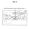
- Fig. 3 is a block diagram illustrating a basic functional configuration of the MFP according to a preferred embodiment of the present invention.
- Fig. 4 is a schematic view illustrating a configuration of the operation panel of the MFP according to a preferred embodiment of the present invention.
- Fig. 5 is a flow chart illustrating a procedure of basic actions of the MFP according to a preferred embodiment of the present invention.
- Fig. 6 is a flow chart illustrating an example of a detailed procedure of actions of the MFP according to a preferred embodiment of the present invention.
- Fig. 7 is a first schematic diagram illustrating an example of actions of the light-emitting unit of the MFP according to a preferred embodiment of the present invention.
- Fig. 8 is a second schematic diagram illustrating an example of actions of the light-emitting unit of the MFP according to a preferred embodiment of the present invention.
- Fig. 9 is a block diagram illustrating an extended example of the functional configuration of the MFP according to a preferred embodiment of the present invention.
- Fig. 10A is a schematic diagram illustrating an example of a first configuration of data of light-emitting action information of the MFP according to a preferred embodiment of the present invention.
- Fig. 10B is a schematic diagram illustrating an example of a second configuration of data of the light-emitting action information of the MFP according to a preferred embodiment of the present invention.
- Fig. 11 is a partial view of the operation panel, which separately arranges the light-emitting unit and a logout key of the MFP according to a preferred embodiment of the present invention.
- Fig. 1 is an external view of an MFP according to a preferred embodiment of the present invention.
- Fig. 2 illustrates a hardware configuration of the MFP according to a preferred embodiment of the present invention.
- a MFP 1 includes a central processing unit (CPU) 10, a read only memory (ROM) 11, a random access memory (RAM) 12, a modem 13, a network control unit (NCU) 14, an operation panel 15, a display 16, a scanner 17, a printer 18 and a local area network interface (LAN I/F) 19 as a hardware configuration.
- CPU central processing unit
- ROM read only memory
- RAM random access memory
- NCU network control unit
- operation panel a display 16
- scanner 17 a scanner 17, a printer 18
- LAN I/F local area network interface
- the CPU 10 is a processor arranged to perform a control program 20 stored in the ROM 11.
- the ROM 11 is a read only memory arranged to hold the control program 20 and the like.
- the RAM 12 is a read-write memory arranged to be used as a work area when the CPU 10 performs the control program 20. Further, the RAM 12 temporarily holds image data read by the scanner 17 and the like.
- the modem 13 is a facsimile modem arranged to modulate image data to be sent out through a facsimile transmission or to demodulate image data sent from the outside through the facsimile transmission.
- the NCU 14 is a line terminating equipment connected to the public switched telephone network (PSTN).
- PSTN public switched telephone network
- the operation panel 15 is a panel arranged to accept an entry by a user.
- the panel 15 accepts the identification information to login, an instruction to start copying and the like.
- the display 16 is a liquid crystal display LCD or the like. According to the embodiment, a touch panel, which allows a user to operate the MFP 1 by touching an image and the like displayed thereon, is adopted as the display 16. To that end, the display 16 could therefore accept an entry of an instruction which the user enters by touching while displaying the state of the MFP 1.
- the scanner 17 is a device arranged to generate document data by reading a document optically with a charge coupled device image sensor (CCD).
- CCD charge coupled device image sensor
- the printer 18 is a printing device arranged to print out, for example, image data generated by the scanner 17 and the like. Further, the printer 18 prints out image data sent from another facsimile device and the like through the PSTN, the NCU 14 and the modem 13.
- the LAN I/F 19 is a communication adapter arranged to connect the MFP 1 with a LAN.
- Fig. 3 is a block diagram illustrating a basic functional configuration of the MFP 1 according to a preferred embodiment of the present invention
- the MFP 1 includes a display unit 100, an accepting unit 110, a controlling unit 120, a detecting unit 121 and a light-emitting unit 130.
- the display unit 100 is a process unit provided with a screen, which represents the state of the MFP 1 such as a parameter set for the MFP 1, information of an ongoing process of the MFP 1 and the like.
- the process is realized, for example, by the display 16 controlled by the CPU 10.
- the accepting unit 110 is a process unit arranged to accept the identification information to be used to log into the MFP 1 and a starting instruction to cause the MFP 1 to start a predetermined process.
- the process is realized, for example, with the operation panel 15 controlled by the CPU 10.
- the controlling unit 120 is a process unit for control of actions of the MFP 1, and for example, the control is achieved by the CPU 10 performing the control program 20. More specifically, the controlling unit 120 controls actions of the scanner 17, the printer 18 and the like of the MFP 1.
- controlling unit 120 authenticates the identification information accepted by the accepting unit 110, the controlling unit 120 causes the MFP 1 to change from the login state to the logout state. Then, after the logout operation is performed on the MFP 1, the controlling unit 120 causes the MFP to change from the login state to the logout state.
- the detecting unit 121 is a process unit arranged to detect an operation for the light-emitting unit 30 and elements of the MFP 1 other than the light-emitting unit 30 (for example, a key on the operation panel 15, the scanner 17 and the printer 18).
- the light-emitting unit 130 is a light-emitting device, which includes light-emitting elements such as light-emitting diode (LED) and performs predetermined light-emitting actions. Further, according to the embodiment, the light-emitting unit 130 also functions as a logout key to cause the MFP 1 to logout.
- LED light-emitting diode
- the light-emitting unit 130 starts the light-emitting action when the MFP 1 changes from the logout state to the login state, and terminates the light-emitting action when the MFP 1 changes from the login state to the logout state.
- the detecting unit 121 detects that the light-emitting unit 130 is pushed down.
- the controlling unit 120 causes the MFP 1 to change from the login state to the logout state when the detecting unit 121 detects that the light-emitting unit 130 is pushed down.
- the light-emitting unit 130 includes a function to prompt a user to perform the logout operation by emitting light and a function as the logout key to accept the logout operation by the user.
- Fig. 4 is a schematic view illustrating a configuration of the operation panel 15 according to a preferred embodiment of the present invention.
- the operation panel 15 is provided with an entry unit 320 including a numeric key group 322. Further, according to a preferred embodiment of the present invention, the display 16 is mounted into the operation panel 15.
- the display 16 displays a login ID entry field 350 where a login ID, which is the identification information used to log into the MFP 1, is to be entered.
- a user enters a login ID, which is assigned to the user, into the login ID enter field 350 by using the numeric key group 322. Then, the user touches a login button 351 displayed on the display 16. Accordingly, the user logs into the MFP 1. In other words, the MFP 1 changes from the logout state to the login state when the login ID is authenticated.
- numeric key group 322, a start key 330, a stop key 331, and other operation keys are arranged on the operation panel 15, and the light-emitting unit 130 is arranged close to the start key 330.
- the light-emitting unit 130 is arranged closer to the start key 330 than any other operation keys except the start key 330 on the operation panel 15.
- the start key 330 is a key for providing the starting instruction of a process such as copying to the MFP 1, and is the key, which a user never fails to use.
- the light-emitting unit 130 which is arranged close to the start key 330, could prompt a user effectively to perform the logout operation.
- Fig. 5 is a flow chart illustrating a procedure of basic actions of the MFP 1 according to a preferred embodiment of the present invention.
- the accepting unit 110 accepts an entry of a login ID (S10). More specifically, the accepting unit 110 accepts the login ID, which is entered into the login ID enter field 350.
- the accepting unit 110 provides the login ID to the controlling unit 120.
- the controlling unit 120 causes the MFP 1 to change from the logout state to the login state when the controlling unit 120 authenticates the login ID (S11).
- the light-emitting unit 130 starts the light-emitting action when the MFP 1 changes from the logout state to the login state (S12).
- the controlling unit 120 causes the MFP 1 to change from the login state to the logout state (S13).
- the light-emitting unit 130 terminates the light-emitting action when the MFP 1 changes from the login state to the logout state (S14).
- Fig. 6 is a flow chart illustrating an example of a procedure of detailed actions of the MFP 1 according to a preferred embodiment of the present invention.
- Fig. 7 is a diagram illustrating an example of actions of the light-emitting unit 130 according to a preferred embodiment of the present invention.
- the accepting unit 110 firstly accepts a login ID (S20), and the controlling unit 120 confirms the legitimacy of the accepted login ID(S21).
- the controlling unit 120 causes the MFP 1 to change from the logout state to the login state as described above (S22).
- the MFP 1 becomes able to perform a predetermined process such as copying. Further, what kind of process could be performed may depend on, for example, each login ID.
- the light-emitting unit 130 starts lighting, which is triggered by, for example, the change of MFP 1 to the login state (S23). Consequently, the user is informed that the MFP 1 is in the login state.
- the user subsequently, for example, sets a document on the scanner 17 to push down the start key 330, thereby making the accepting unit 100 accept the starting instruction for starting copying (S24).
- the MFP 1 starts the process represented by the starting instruction, i.e., a process for copying the document (S25).
- the light-emitting unit 130 changes the ongoing light-emitting action from lighting to blinking, which is triggered by, for example, the acceptance of the starting instruction at the accepting unit 110(S26).
- the operation by the user for the process for copying the document is completed when the start key 330 is pushed down so that the MFP 1 could logout at anytime.
- the light-emitting unit 130 could lead the user effectively to perform the logout operation by changing the ongoing light-emitting action from lighting to blinking.
- the detecting unit 121 detects the operation as the logout operation.
- the controlling unit 120 causes the MFP 1 to change from the login state to the logout state (S28). As a result, any process such as copying, which could be performed when the MFP 1 changes to the login state (S22), could not be performed.
- the light-emitting unit 130 terminates lighting, which is triggered by, for example, the change of the MFP 1 to the logout state. In other words, the light-emitting unit 130 turns the light off (S29).
- the light-emitting unit 130 starts, terminates or changes an action, for example, according to a controlling signal from the controlling unit 120.
- Fig. 7 is a first schematic diagram illustrating an example of actions of the light-emitting unit 130 according to a preferred embodiment of the present invention.
- the MFP 1 changes to the login state, thereby making the light-emitting unit 130 start lighting, i.e., start continuous light-emitting. Subsequently, the start key 330 is pushed down, thereby making the light-emitting unit 130 change the ongoing light-emitting action from lighting to blinking, which repeats lighting and extinction. After that, the light-emitting unit 130 is pushed down, thereby making the light-emitting unit 130 turn the light off.
- start key 330 is pushed down, thereby making the light-emitting unit 130 change the ongoing light-emitting action from lighting to blinking, which repeats lighting and extinction.
- the light-emitting unit 130 is pushed down, thereby making the light-emitting unit 130 turn the light off.
- the start key 330 is pushed down, i.e., the accepting unit 110 accepts the starting instruction for any process, thereby making the light-emitting unit 130 change the ongoing light-emitting action.
- the MFP 1 could be required to copy another document.
- the light-emitting action of the light-emitting unit 130 which is changed from lighting to blinking, changes back to the pre-changed lighting.
- Fig. 8 is a second schematic diagram illustrating an example of actions of the light-emitting unit 130 according to a preferred embodiment of the present invention.
- the detecting unit 121 detects an operation, which is performed on elements other than the light-emitting unit 130, after the light-emitting unit 130 changes the light-emitting action from lighting to blinking, the light-emitting unit 130 changes back the light-emitting action from blinking to lighting.
- the operation performed on elements other than the light-emitting unit 130 may be, for example, setting a document on the scanner 17, changing a setting for the MFP 1 by using the operation panel 15 or the like.
- the detecting unit 121 detects the operation for the new process.
- the light-emitting unit 130 changes back the light-emitting action from blinking to lighting. Further, when the start key 330 is pushed down to start the new process after the light-emitting unit 130 changes from blinking to lighting, the light-emitting unit 130 changes back the light-emitting action from lighting to blinking.
- the light-emitting unit 130 changes the light-emitting action as described above, it becomes possible to lead a user more certainly to perform the logout operation. For example, when a user performs several processes continuously, performing the logout operation by mistake by the user during the time from the start of a process to the start of the next process is prevented.
- the light-emitting unit 130 may change the light-emitting action by changing color, brightness and a blinking cycle.
- the light-emitting unit 130 may emit green light when the MFP 1 changes from the logout state to the login state, and may change the emission color from green to red by pushing down the starting key 330.
- the light-emitting unit 130 may emit light at predetermined intensity when the MFP 1 changes from the logout state to the login state, and then may be changed to emit light at higher intensity than the predetermined intensity by pushing down the start key 330.
- the light-emitting unit 130 lighted by the login may be made to emit brighter light by pushing down the start key 330.
- the light-emitting unit 130 may blink at a predetermined cycle when the MFP 1 changes from the logout state to the login state, and then may be made to blink at a shorter cycle or a longer cycle than the predetermined cycle by pushing down the start key 330.
- the light-emitting unit 130 could change the light-emitting action on user basis to inform that the MFP 1 is in the login state.
- the MFP 1 stores, for example, the light-emitting action information, which makes the login ID correspond to the light-emitting action. Further, the light-emitting unit 130 performs the light-emitting action corresponding to the login ID, which was used to login, according to the light-emitting action information.
- Fig. 9 is a block diagram illustrating an example of an extended functional configuration of the MFP 1 according to a preferred embodiment of the present invention.
- the MFP 1 illustrated in Fig. 9 includes not only function blocks of the MFP 1 illustrated in Fig. 3 but also a light-emitting action information storing unit 140.
- the controlling unit 120 when the controlling unit 120 authenticates the login ID, the controlling unit 120 identifies information representing the light-emitting action corresponding to the login ID by referring to the light-emitting action information stored in the light-emitting action information storing unit 140.
- Fig. 10A is a schematic diagram illustrating an example of a first configuration of data of the light-emitting action information according to a preferred embodiment of the present invention.
- the controlling unit 120 authenticates the login ID "P100"
- the controlling unit 120 identifies the light-emitting color "red” corresponding to "P100” by referring to the light-emitting action information 141 illustrated in Fig. 10A .
- the controlling unit 120 notifies the light-emitting unit 130 of information representing the light-emitting color "red".
- the light-emitting unit 130 receives the information representing the light-emitting color "red” from the controlling unit 120 and emits red light.
- the light-emitting unit 130 could inform with the red light that the MFP 1 changes to the login state with the authentication of "P100".
- the start key 330 when the start key 330 is pushed down, for example, the user is informed with the blinking of the red light that the logout operation could be performed. Further, the light-emitting color may be changed to, for example, a color which is not registered in the light-emitting action information when the start key 330 is pushed down.
- the blinking pattern may be changed for each login ID.
- Fig. 10B is a schematic diagram illustrating an example of a second configuration of data of the light-emitting action information according to a preferred embodiment of the present invention.
- the controlling unit 120 authenticates the login ID "P100"
- the controlling unit 120 identifies the blinking pattern "A" corresponding to "P100” by referring to the light-emitting action information 142 illustrated in Fig. 10B .
- the controlling unit 120 notifies the light emitting unit 130 of information representing the blinking pattern "A".
- the light-emitting unit 130 receives the information representing the blinking pattern "A” from the controlling unit 120 and repeats lighting and extinction according to the pattern corresponding to "A".
- the light-emitting unit 130 has specific information corresponding to each one of the blinking patterns.
- the light-emitting unit 130 has information, as the information corresponding to "A", representing that lighting for 1 second and extinction for 0.5 second are repeated.
- controlling unit 120 may notify the light-emitting unit 130 of the specific information representing a blinking cycle and the like instead of the information representing the blinking pattern. Furthermore, the specific information such as the information representing the blinking cycle and the like may be registered as the light-emitting action information for each login ID.
- the light-emitting unit 130 could inform with the blinking pattern corresponding to "P100" that the MFP 1 changes to the login state with the authentication of "P100".
- the light-emitting unit 130 changes to a blinking pattern, which is not registered in the light-emitting action information. Further, the light-emitting unit 130, for example, may not change the blinking pattern but the light-emitting color when the start key 330 is pushed down.
- the MFP 1 includes the light-emitting unit 130, which is arranged separately from the display unit 100.
- the light-emitting unit 130 starts the light-emitting action when the MFP 1 changes from the logout state to the login state and terminates the light-emitting action when the MFP 1 changes from the login state to the logout state.
- the MFP 1 could prompt a user to logout by the action of the light-emitting which is easy to visually recognize. Therefore, it becomes possible to prompt a user effectively to perform the logout operation.
- the light-emitting unit 130 is arranged separately from the display unit 100 arranged to display the state of the MFP 1. More specifically, the light-emitting unit 130 is arranged on the operation panel 15 as a separate body from the display 16, which functions as the display unit 100. Accordingly, it becomes possible to increase the certainty of the logout while the display area of the display 16 is not consumed for leading a user to perform the logout operation.
- the light-emitting unit 130 also functions as the logout key to cause the MFP 1 to logout.
- the light-emitting unit 130 and the logout key 131 could be arranged separately.
- the light-emitting unit 130 starts the light-emitting action when the MFP 1 changes to the login state, that the light-emitting unit 130 starts lighting or blinking, which is triggered by the change of the MFP 1 to the login state.
- the light-emitting unit 130 may start the light-emitting action at different timing.
- the light-emitting unit 130 may start the light-emitting action, which is triggered by, for example, the authentication of the login ID at the controlling unit 120. Further, the light-emitting unit 130 may start the light-emitting action, which is triggered by, for example, an operation for settings by using the numeric key group 322 after the MFP 1 changes to the login state.
- the light-emitting unit 130 may start the light-emitting action, which is triggered by, for example, pushing down the start key 330 after the MFP 1 changes to the login state.
- any of the above cases substantially falls under the action in which the light-emitting unit 130 starts the light-emitting action when the MFP 1 changes to the login state. Consequently, in any of the above cases, it becomes possible to prompt a user effectively to perform the logout operation.
- the MFP 1 may prompt a user to perform the logout operation, for example, by sound, in addition to the light-emitting action of the light-emitting unit 130.
- the MFP 1 could prompt a user to perform the logout operation by, for example, a voice message such as "you could logout now” or the like, when the start key 330 is pushed down after the MFP 1 changes to the login state.
- the MFP 1 changes to the login state when a login ID is authenticated.
- the MFP 1 may change to the login state, for example, when both the login ID and a password are authenticated.
- the present invention could provide a MFP, which could increase the certainty of the logout after the login. Therefore, the present invention is useful especially in MFPs and the like, which include a scanner, a printer and the like.
Landscapes
- Engineering & Computer Science (AREA)
- Multimedia (AREA)
- Signal Processing (AREA)
- Facsimiles In General (AREA)
- Accessory Devices And Overall Control Thereof (AREA)
- Control Or Security For Electrophotography (AREA)
Applications Claiming Priority (1)
| Application Number | Priority Date | Filing Date | Title |
|---|---|---|---|
| JP2010073873A JP5625433B2 (ja) | 2010-03-26 | 2010-03-26 | 複合機 |
Publications (1)
| Publication Number | Publication Date |
|---|---|
| EP2369833A1 true EP2369833A1 (de) | 2011-09-28 |
Family
ID=44148827
Family Applications (1)
| Application Number | Title | Priority Date | Filing Date |
|---|---|---|---|
| EP11158302A Withdrawn EP2369833A1 (de) | 2010-03-26 | 2011-03-15 | Multifunktions-Peripheriegerät |
Country Status (5)
| Country | Link |
|---|---|
| US (1) | US20110235087A1 (de) |
| EP (1) | EP2369833A1 (de) |
| JP (1) | JP5625433B2 (de) |
| KR (1) | KR20110108243A (de) |
| CN (1) | CN102202150A (de) |
Cited By (1)
| Publication number | Priority date | Publication date | Assignee | Title |
|---|---|---|---|---|
| JP2018181375A (ja) * | 2018-07-27 | 2018-11-15 | キヤノン株式会社 | 情報処理装置、その制御方法、及びプログラム |
Families Citing this family (7)
| Publication number | Priority date | Publication date | Assignee | Title |
|---|---|---|---|---|
| JP5831695B2 (ja) * | 2011-09-13 | 2015-12-09 | 富士ゼロックス株式会社 | 情報処理装置、情報処理システムおよびプログラム |
| JP6614908B2 (ja) * | 2014-12-25 | 2019-12-04 | キヤノン株式会社 | ログインのための誘導表示を行う装置、該装置の制御方法、及びプログラム。 |
| JP6055853B2 (ja) * | 2015-02-18 | 2016-12-27 | 京セラドキュメントソリューションズ株式会社 | 表示入力装置およびそれを備えた画像形成装置 |
| JP6990994B2 (ja) * | 2017-05-26 | 2022-01-12 | キヤノン株式会社 | 情報処理装置、その制御方法、及びプログラム |
| JP6383463B2 (ja) * | 2017-06-13 | 2018-08-29 | キヤノン株式会社 | 情報処理装置、その制御方法、及びプログラム |
| JP2022155592A (ja) * | 2019-08-26 | 2022-10-14 | 京セラドキュメントソリューションズ株式会社 | 電子機器、電子機器の制御方法及び制御プログラム |
| JP7368983B2 (ja) * | 2019-09-05 | 2023-10-25 | キヤノン株式会社 | 印刷装置、通知制御方法及びプログラム |
Citations (3)
| Publication number | Priority date | Publication date | Assignee | Title |
|---|---|---|---|---|
| US20070136293A1 (en) * | 2005-11-29 | 2007-06-14 | Wataru Mizumukai | Peripheral device |
| CN201349240Y (zh) * | 2008-11-07 | 2009-11-18 | 鸿富锦精密工业(深圳)有限公司 | 具有特定信息提示的电子装置 |
| CN201349242Y (zh) * | 2008-11-05 | 2009-11-18 | 鸿富锦精密工业(深圳)有限公司 | 具有来电提示的通信装置 |
Family Cites Families (13)
| Publication number | Priority date | Publication date | Assignee | Title |
|---|---|---|---|---|
| KR0157847B1 (ko) * | 1993-04-07 | 1999-05-15 | 미따라이 하지메 | 정보 출력 장치 및 정보 출력 방법 |
| EP0911752A3 (de) * | 1997-10-27 | 2003-12-17 | Canon Kabushiki Kaisha | Informationsverarbeitungsgerät mit einer zusätzlichen Funktionseinheit |
| US6917373B2 (en) * | 2000-12-28 | 2005-07-12 | Microsoft Corporation | Context sensitive labels for an electronic device |
| US6603937B2 (en) * | 2000-07-18 | 2003-08-05 | Sharp Kabushiki Kaisha | Image forming apparatus |
| JP2002200827A (ja) * | 2000-11-06 | 2002-07-16 | Ricoh Co Ltd | 画像形成装置、画像形成方法およびその方法をコンピュータに実行させるプログラム |
| US7372371B2 (en) * | 2003-05-05 | 2008-05-13 | Microsoft Corporation | Notification lights, locations and rules for a computer system |
| JP2005266699A (ja) * | 2004-03-22 | 2005-09-29 | Canon Inc | 表示制御方法及び画像処理装置 |
| JP4403053B2 (ja) * | 2004-11-12 | 2010-01-20 | 三菱電機株式会社 | 指紋読取装置 |
| JP4371096B2 (ja) * | 2005-10-07 | 2009-11-25 | 村田機械株式会社 | 画像処理装置 |
| JP4944516B2 (ja) * | 2006-06-30 | 2012-06-06 | 京セラミタ株式会社 | 画像形成装置 |
| JP4760612B2 (ja) * | 2006-08-28 | 2011-08-31 | 富士ゼロックス株式会社 | 画像形成装置、画像形成システム及びプログラム |
| JP4725621B2 (ja) * | 2008-09-19 | 2011-07-13 | コニカミノルタビジネステクノロジーズ株式会社 | 画像形成装置、画像形成装置の制御方法および画像形成装置で実行されるプログラム |
| JP4849122B2 (ja) * | 2008-12-16 | 2012-01-11 | コニカミノルタビジネステクノロジーズ株式会社 | 画像処理装置およびサーバ装置 |
-
2010
- 2010-03-26 JP JP2010073873A patent/JP5625433B2/ja not_active Expired - Fee Related
-
2011
- 2011-01-31 KR KR1020110009449A patent/KR20110108243A/ko not_active Ceased
- 2011-03-11 CN CN2011100616927A patent/CN102202150A/zh active Pending
- 2011-03-15 EP EP11158302A patent/EP2369833A1/de not_active Withdrawn
- 2011-03-25 US US13/072,548 patent/US20110235087A1/en not_active Abandoned
Patent Citations (5)
| Publication number | Priority date | Publication date | Assignee | Title |
|---|---|---|---|---|
| US20070136293A1 (en) * | 2005-11-29 | 2007-06-14 | Wataru Mizumukai | Peripheral device |
| CN201349242Y (zh) * | 2008-11-05 | 2009-11-18 | 鸿富锦精密工业(深圳)有限公司 | 具有来电提示的通信装置 |
| US20100113103A1 (en) * | 2008-11-05 | 2010-05-06 | Hon Hai Precision Industry Co., Ltd. | Communication apparatus with incoming call prompt |
| CN201349240Y (zh) * | 2008-11-07 | 2009-11-18 | 鸿富锦精密工业(深圳)有限公司 | 具有特定信息提示的电子装置 |
| US20100117851A1 (en) * | 2008-11-07 | 2010-05-13 | Hon Hai Precision Industry Co., Ltd. | Electronic apparatus with incoming message prompt |
Cited By (1)
| Publication number | Priority date | Publication date | Assignee | Title |
|---|---|---|---|---|
| JP2018181375A (ja) * | 2018-07-27 | 2018-11-15 | キヤノン株式会社 | 情報処理装置、その制御方法、及びプログラム |
Also Published As
| Publication number | Publication date |
|---|---|
| JP2011211261A (ja) | 2011-10-20 |
| US20110235087A1 (en) | 2011-09-29 |
| JP5625433B2 (ja) | 2014-11-19 |
| CN102202150A (zh) | 2011-09-28 |
| KR20110108243A (ko) | 2011-10-05 |
Similar Documents
| Publication | Publication Date | Title |
|---|---|---|
| EP2369833A1 (de) | Multifunktions-Peripheriegerät | |
| US8902444B2 (en) | Image processing apparatus and method, including user authentication, and storage medium | |
| CN101998008A (zh) | 复合机和系统 | |
| US10514870B2 (en) | Image forming apparatus that executes jobs, control method therefor, and storage medium | |
| US20080201775A1 (en) | Multifunction peripheral, password setting system, method and computer readable medium for password setting | |
| JP4297023B2 (ja) | 外部記憶装置の記憶情報処理装置及び同処理方法 | |
| US20210306522A1 (en) | Image processing apparatus and image processing system | |
| JP2026012783A (ja) | 画像処理装置 | |
| JP5644751B2 (ja) | 画像形成装置、及び画像形成装置の制御プログラム | |
| JP4709254B2 (ja) | 認証システム及び端末装置 | |
| JP2010093635A (ja) | 画像形成装置 | |
| JP2020155890A (ja) | 画像処理装置、画像処理方法および画像処理プログラム | |
| US12093584B2 (en) | Information processing apparatus, control method of information processing apparatus, and storage medium | |
| JP5170415B2 (ja) | 情報処理装置および情報処理プログラム | |
| CN111064854A (zh) | 图像形成装置 | |
| CN111064855A (zh) | 图像形成装置 | |
| JP2018129640A (ja) | 画像形成装置 | |
| JP2017118420A (ja) | 情報処理装置、その制御方法、及びプログラム | |
| JP2008015949A (ja) | 画像処理装置 | |
| JP6919414B2 (ja) | 情報処理装置及びプログラム | |
| JP2020102067A (ja) | 画像形成装置、画像形成装置の操作ボタンの点灯表示方法及びプログラム | |
| US12405756B2 (en) | Printing apparatus capable of improving convenience of setting sheet settings, method of controlling printing apparatus, and storage medium | |
| JP6204280B2 (ja) | 画像読取装置 | |
| US20050017075A1 (en) | Image-processing apparatus having a lock button | |
| JP2023102608A (ja) | 原稿読取装置および原稿忘れの警告表示方法 |
Legal Events
| Date | Code | Title | Description |
|---|---|---|---|
| PUAI | Public reference made under article 153(3) epc to a published international application that has entered the european phase |
Free format text: ORIGINAL CODE: 0009012 |
|
| AK | Designated contracting states |
Kind code of ref document: A1 Designated state(s): AL AT BE BG CH CY CZ DE DK EE ES FI FR GB GR HR HU IE IS IT LI LT LU LV MC MK MT NL NO PL PT RO RS SE SI SK SM TR |
|
| AX | Request for extension of the european patent |
Extension state: BA ME |
|
| 17P | Request for examination filed |
Effective date: 20120130 |
|
| STAA | Information on the status of an ep patent application or granted ep patent |
Free format text: STATUS: THE APPLICATION HAS BEEN WITHDRAWN |
|
| 18W | Application withdrawn |
Effective date: 20160128 |