EP2369584A1 - Recording medium, method and apparatus for reproducing data on the recording medium, and method and apparatus for recording data on the recording medium - Google Patents
Recording medium, method and apparatus for reproducing data on the recording medium, and method and apparatus for recording data on the recording medium Download PDFInfo
- Publication number
- EP2369584A1 EP2369584A1 EP11169366A EP11169366A EP2369584A1 EP 2369584 A1 EP2369584 A1 EP 2369584A1 EP 11169366 A EP11169366 A EP 11169366A EP 11169366 A EP11169366 A EP 11169366A EP 2369584 A1 EP2369584 A1 EP 2369584A1
- Authority
- EP
- European Patent Office
- Prior art keywords
- recorded
- bits
- information
- data
- recording medium
- Prior art date
- Legal status (The legal status is an assumption and is not a legal conclusion. Google has not performed a legal analysis and makes no representation as to the accuracy of the status listed.)
- Withdrawn
Links
Images


Classifications
-
- G—PHYSICS
- G11—INFORMATION STORAGE
- G11B—INFORMATION STORAGE BASED ON RELATIVE MOVEMENT BETWEEN RECORD CARRIER AND TRANSDUCER
- G11B7/00—Recording or reproducing by optical means, e.g. recording using a thermal beam of optical radiation by modifying optical properties or the physical structure, reproducing using an optical beam at lower power by sensing optical properties; Record carriers therefor
- G11B7/007—Arrangement of the information on the record carrier, e.g. form of tracks, actual track shape, e.g. wobbled, or cross-section, e.g. v-shaped; Sequential information structures, e.g. sectoring or header formats within a track
-
- G—PHYSICS
- G11—INFORMATION STORAGE
- G11B—INFORMATION STORAGE BASED ON RELATIVE MOVEMENT BETWEEN RECORD CARRIER AND TRANSDUCER
- G11B20/00—Signal processing not specific to the method of recording or reproducing; Circuits therefor
- G11B20/10—Digital recording or reproducing
- G11B20/12—Formatting, e.g. arrangement of data block or words on the record carriers
- G11B20/1217—Formatting, e.g. arrangement of data block or words on the record carriers on discs
-
- G—PHYSICS
- G11—INFORMATION STORAGE
- G11B—INFORMATION STORAGE BASED ON RELATIVE MOVEMENT BETWEEN RECORD CARRIER AND TRANSDUCER
- G11B20/00—Signal processing not specific to the method of recording or reproducing; Circuits therefor
- G11B20/10—Digital recording or reproducing
- G11B20/12—Formatting, e.g. arrangement of data block or words on the record carriers
- G11B20/1217—Formatting, e.g. arrangement of data block or words on the record carriers on discs
- G11B2020/1218—Formatting, e.g. arrangement of data block or words on the record carriers on discs wherein the formatting concerns a specific area of the disc
- G11B2020/1221—Formatting, e.g. arrangement of data block or words on the record carriers on discs wherein the formatting concerns a specific area of the disc cluster, i.e. a data structure which consists of a fixed number of sectors or ECC blocks
-
- G—PHYSICS
- G11—INFORMATION STORAGE
- G11B—INFORMATION STORAGE BASED ON RELATIVE MOVEMENT BETWEEN RECORD CARRIER AND TRANSDUCER
- G11B20/00—Signal processing not specific to the method of recording or reproducing; Circuits therefor
- G11B20/10—Digital recording or reproducing
- G11B20/12—Formatting, e.g. arrangement of data block or words on the record carriers
- G11B20/1217—Formatting, e.g. arrangement of data block or words on the record carriers on discs
- G11B2020/1218—Formatting, e.g. arrangement of data block or words on the record carriers on discs wherein the formatting concerns a specific area of the disc
- G11B2020/1222—ECC block, i.e. a block of error correction encoded symbols which includes all parity data needed for decoding
-
- G—PHYSICS
- G11—INFORMATION STORAGE
- G11B—INFORMATION STORAGE BASED ON RELATIVE MOVEMENT BETWEEN RECORD CARRIER AND TRANSDUCER
- G11B20/00—Signal processing not specific to the method of recording or reproducing; Circuits therefor
- G11B20/10—Digital recording or reproducing
- G11B20/12—Formatting, e.g. arrangement of data block or words on the record carriers
- G11B2020/1264—Formatting, e.g. arrangement of data block or words on the record carriers wherein the formatting concerns a specific kind of data
- G11B2020/1265—Control data, system data or management information, i.e. data used to access or process user data
- G11B2020/1267—Address data
-
- G—PHYSICS
- G11—INFORMATION STORAGE
- G11B—INFORMATION STORAGE BASED ON RELATIVE MOVEMENT BETWEEN RECORD CARRIER AND TRANSDUCER
- G11B20/00—Signal processing not specific to the method of recording or reproducing; Circuits therefor
- G11B20/10—Digital recording or reproducing
- G11B20/18—Error detection or correction; Testing, e.g. of drop-outs
- G11B20/1816—Testing
- G11B2020/1823—Testing wherein a flag is set when errors are detected or qualified
-
- G—PHYSICS
- G11—INFORMATION STORAGE
- G11B—INFORMATION STORAGE BASED ON RELATIVE MOVEMENT BETWEEN RECORD CARRIER AND TRANSDUCER
- G11B20/00—Signal processing not specific to the method of recording or reproducing; Circuits therefor
- G11B20/10—Digital recording or reproducing
- G11B20/18—Error detection or correction; Testing, e.g. of drop-outs
- G11B20/1833—Error detection or correction; Testing, e.g. of drop-outs by adding special lists or symbols to the coded information
- G11B2020/1846—Error detection or correction; Testing, e.g. of drop-outs by adding special lists or symbols to the coded information using a picket code, i.e. a code in which a long distance code [LDC] is arranged as an array and columns containing burst indicator subcode [BIS] are multiplexed for erasure decoding
-
- G—PHYSICS
- G11—INFORMATION STORAGE
- G11B—INFORMATION STORAGE BASED ON RELATIVE MOVEMENT BETWEEN RECORD CARRIER AND TRANSDUCER
- G11B20/00—Signal processing not specific to the method of recording or reproducing; Circuits therefor
- G11B20/10—Digital recording or reproducing
- G11B20/18—Error detection or correction; Testing, e.g. of drop-outs
- G11B20/1883—Methods for assignment of alternate areas for defective areas
- G11B2020/1893—Methods for assignment of alternate areas for defective areas using linear replacement to relocate data from a defective block to a non-contiguous spare area, e.g. with a secondary defect list [SDL]
-
- G—PHYSICS
- G11—INFORMATION STORAGE
- G11B—INFORMATION STORAGE BASED ON RELATIVE MOVEMENT BETWEEN RECORD CARRIER AND TRANSDUCER
- G11B2220/00—Record carriers by type
- G11B2220/20—Disc-shaped record carriers
- G11B2220/25—Disc-shaped record carriers characterised in that the disc is based on a specific recording technology
- G11B2220/2537—Optical discs
- G11B2220/2541—Blu-ray discs; Blue laser DVR discs
-
- G—PHYSICS
- G11—INFORMATION STORAGE
- G11B—INFORMATION STORAGE BASED ON RELATIVE MOVEMENT BETWEEN RECORD CARRIER AND TRANSDUCER
- G11B2220/00—Record carriers by type
- G11B2220/20—Disc-shaped record carriers
- G11B2220/25—Disc-shaped record carriers characterised in that the disc is based on a specific recording technology
- G11B2220/2537—Optical discs
- G11B2220/2579—HD-DVDs [high definition DVDs]; AODs [advanced optical discs]
Definitions
- aspects of the present invention relate to a recording medium, a method and apparatus for reproducing data on the recording medium, and a method and apparatus for recording data on the recording medium.
- High density recording media have been developed recently and allow large amounts of high quality video and audio data to be recorded and stored thereon.
- Examples of such high density recording media include Blu-ray discs (BD), high definition digital versatile discs (HD-DVD), and disks with even higher recording densities than those of BDs and HD-DVDs.
- the above high density recording media are based on a next-generation recording medium technology.
- the high density recording media are next-generation optical recording solutions that can store amounts of data far exceeding those of conventional recording media (such as DVDs). Furthermore, the development of such high density recording media has recently been carried out together with other digital devices.
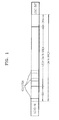
- FIG. 1 is a diagram illustrating a structure of a recording area of a high density optical recording medium.
- the optical recording medium is divided into 3 parts: a lead-in area, a data area and a lead-out area.
- the data area includes a user data area, in which actual user data is recorded, and a spare area to replace a defective area in the user data area.
- the spare area includes an inner spare area (ISA) located in an inner portion of the data area, and an outer spare area (OSA) located in an outer portion of the data area.
- ISA inner spare area
- OSA outer spare area
- each cluster is divided into a plurality of recording units.
- the recording unit is referred to as a sector
- each cluster includes a total of 32 sectors, and one address unit number (AUN) is assigned to every two sectors.
- AUN address unit number
- a total of 16 AUN addresses are recorded. From the recorded AUNs, the address location of each sector can be confirmed.
- the confirmed sector address is referred to as a physical sector number (PSN).
- PSN physical sector number
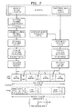
- FIG. 2 is a diagram illustrating a structure of a data frame recorded on the high density optical recording medium.
- ECC error correction code
- data to be recorded is formed with user data desired to be recorded and user control data (201).
- a 4-byte error detection code (EDC) is added to the user data, thereby forming a data frame (202).
- the data frame forms a scramble data frame (203).
- Each column of the scramble data frame is again rearranged, thereby forming one data block comprised of 304 columns x 216 lines (204).
- a Reed-Solomon (RS) code is added to the data block, thereby forming a long distance code (LDC) block (205). Then, using an interleaving process to prevent a concentrated occurrence of errors, the LDC block is transformed to form an LDC cluster of 152 columns x 496 lines (206).
- RS Reed-Solomon
- the user control data forms an access block so that a recording and reproducing apparatus can access data in a corresponding cluster having 24 columns x 30 lines (208).
- an RS code is added to the access block, thereby forming a BIS block having an additional 32 lines of parity (209).
- the BIS block is transformed to form a BIS cluster of 3 columns x 496 lines (210).
- the LDC cluster and the BIS cluster are divided and arranged in order of LDC, BIS, LDC, BIS, LDC, BIS, LDC, thereby forming a 155 byte ECC cluster (211).
- Each LDC has a 38 byte size, and each BIS has a 1 byte size in the data frame.
- synchronization information and the like are added to the formed ECC cluster, and recorded in a predetermined cluster in the data area (212).
- the resultant frame has a 20 bit frame sync, and alternating pairs of 25 bit data and 1 bit DC control data.
- the capacity of recording media having a data structure as illustrated in FIG. 2 is gradually increasing. However, with the increasing capacity of such recording media, a problem arises in how to secure an address area in the data structure in which the addresses can be recorded.
- aspects of the present invention provide a high density recording medium in which an address area can be secured in a data structure, a method and apparatus for reproducing data on the recording medium, and a method and apparatus for recording data on the recording medium.
- aspects of the present invention can also be embodied as computer-readable codes on a computer-readable recording medium.
- the computer-readable recording medium is any data storage device that can store data which can be thereafter read by a computer system. Examples of the computer-readable recording medium include read-only memory (ROM), random-access memory (RAM), CD-ROMs, magnetic tapes, floppy disks, optical data storage devices, and a computer data signal embodied in a carrier wave comprising a compression source code segment comprising the code and an encryption source code segment comprising the code (such as data transmission through the Internet).
- the computer-readable recording medium can also be distributed over network-coupled computer systems so that the computer-readable code is stored and executed in a distributed fashion.
- Aspects of the present invention may also be realized as a data signal embodied in a carrier wave and comprising a program readable by a computer and transmittable over the Internet.
- each of the clusters includes a plurality of address fields, each address field includes 32-bit address unit number (AUN) address information, and the AUN address information includes: a reserved area recorded on 4 bits; layer information, recorded on 3 bits, indicating a layer on which data corresponding to the AUN address information is recorded; and location information, recorded on 25 bits, indicating a location of the data corresponding to the AUN address information.
- AUN address unit number
- each of the clusters may include a plurality of sectors, and an address field may be allocated to every two sectors of the plurality of sectors.
- each of the clusters may include 16 address fields.
- the reserved area may include state information on defects occurring on the recording medium.
- each of the address fields may further include 1-byte flag information and a 4-byte parity information for the address field.
- the 1-byte flag information may include additional information other than the address information of the cluster.
- each of the clusters includes a plurality of address fields, each address field includes 32-bit AUN address information, and the AUN address information includes: a reserved area recorded on 4 bits; a capacity expansion area recorded on 1 bit; layer information, recorded on 3 bits, indicating a layer on which data corresponding to the AUN address information is recorded; and location information, recorded on 24 bits, indicating a location of data corresponding to the AUN address information.
- each of the clusters may include a plurality of sectors, and an address field may be allocated to every two sectors of the plurality of sectors.
- each of the clusters may include 16 address fields.
- the reserved area may include state information on defects occurring on the recording medium.
- the capacity expansion area may be used when all locations of data corresponding to the AUN address information cannot be expressed by the remaining 24 bits.
- each of the address fields may further include 1-byte flag information and 4-byte parity information for the address field.
- the 1-byte flag information may include additional information other than the address information of the cluster.
- each of the clusters includes a plurality of address fields, each address field includes 32-bit AUN address information, and the AUN address information includes: a reserved area recorded on 5 bits; layer information, recorded on 3 bits, indicating a layer on which data corresponding to the AUN address information is recorded; and location information, recorded on 24 bits, indicating a location of data corresponding to the AUN address information, wherein, in the remaining 24 bits indicating the location of the data corresponding to the AUN address information, the least significant bit is used as a flag to determine one of two separate areas in which data is recorded on the recording medium.
- the least significant bit of each of the address fields may be used to determine either an area indicating 0 or an area indicating 1.
- each of the clusters may include a plurality of sectors, and an address field may be allocated to every two sectors of the plurality of sectors.
- each of the clusters may include 16 address fields.
- the reserved area may include state information on defects occurring on the recording medium.
- each of the address fields may further include 1-byte flag information and 4-byte parity information for the address field.
- the 1-byte flag information may include additional information other than the AUN address information of the cluster.
- a method of reproducing data on a recording medium on which the data is recorded in units of clusters including: moving an optical head unit to a target location of the recording medium at which data corresponding to address information is recorded; and reproducing the data at the target location of the recording medium, wherein each of the clusters includes a plurality of address fields.
- each address field includes 32-bit AUN address information
- the AUN address information includes: a reserved area recorded on 4 bits; layer information, recorded on 3 bits, indicating a layer on which data corresponding to the AUN address information is recorded; and location information, recorded on 25 bits, indicating a location of the data corresponding to the AUN address information.
- a method of reproducing data on a recording medium on which the data is recorded in units of clusters including: moving an optical head unit to a target location of the recording medium at which data corresponding to address information is recorded; and reproducing the data at the target location of the recording medium, wherein each of the clusters includes a plurality of address fields, each address field includes 32-bit AUN address information, and the AUN address information includes: a reserved area recorded on 4 bits; a capacity expansion area recorded on 1 bit; layer information, recorded on 3 bits, indicating a layer on which data corresponding to the AUN address information is recorded; and location information, recorded on 24 bits, indicating a location of data corresponding to the AUN address information.
- a method of reproducing data on a recording medium on which the data is recorded in units of clusters including: moving an optical head unit to a target location of the recording medium at which data corresponding to address information is recorded; and reproducing the data at the target location of the recording medium, wherein each of the clusters includes a plurality of address fields, each address field includes 32-bit AUN address information, and the AUN address information includes: a reserved area recorded on 5 bits; layer information, recorded on 3 bits, indicating a layer on which data corresponding to the AUN address information is recorded; and location information, recorded on 24 bits, indicating a location of the data corresponding to the AUN address information, wherein the least significant bit of the remaining 24 bits indicating the location of the data corresponding to the AUN address information is used as a flag to determine one of two separate areas in which data is recorded on the recording medium.
- an apparatus for reproducing data on a recording medium on which the data is recorded in units of clusters including: a control unit moving an optical head unit to a target location of the recording medium at which data corresponding to address information is recorded; and a pickup unit reproducing the data at the target location of the recording medium, wherein each of the clusters includes a plurality of address fields, each address field includes 32-bit AUN address information, and the AUN address information includes a reserved area recorded on 4 bits; layer information, recorded on 3 bits, indicating a layer on which data corresponding to the AUN address information is recorded; and location information, recorded on 25 bits, indicating a location of the data corresponding to the AUN address information.
- an apparatus for reproducing data on a recording medium on which the data is recorded in units of clusters including: a control unit moving an optical head unit to a target location of the recording medium at which data corresponding to address information is recorded; and a pickup unit reproducing the data at the target location of the recording medium, wherein each of the clusters includes a plurality of address fields, each address field includes 32-bit AUN address information, and the AUN address information includes: a reserved area recorded on 4 bits; a capacity expansion area recorded on 1 bit; layer information, recorded on 3 bits, indicating a layer on which data corresponding to the AUN address information is recorded; and location information, recorded on 24 bits, indicating a location of the data corresponding to the AUN address information.
- an apparatus for reproducing data on a recording medium on which the data is recorded in units of clusters including: a control unit moving an optical head unit to a target location of the recording medium at which data corresponding to address information is recorded; and a pickup unit reproducing the data at the target location of the recording medium, wherein each of the clusters includes a plurality of address fields, each address field includes 32-bit AUN address information, and the AUN address information includes: a reserved area recorded on 5 bits; layer information, recorded on 3 bits, indicating a layer on which data corresponding to the AUN address information is recorded; and location information, recorded on 24 bits, indicating a location of the data corresponding to the AUN address information, wherein the least significant bit of the remaining 24 bits indicating the location of the data corresponding to the AUN address information, is used as a flag to determine one of two separate areas in which data is recorded on the recording medium.
- a method of recording data on a recording medium in units of clusters including: generating a cluster in which addresses and data are recorded; and recording the generated cluster on the recording medium, wherein each of the clusters includes a plurality of address fields, each address field includes 32-bit AUN address information, and the AUN address information includes: a reserved area recorded on 4 bits; layer information, recorded on 3 bits, indicating a layer on which data corresponding to the AUN address information is recorded; and location information, recorded on 25 bits, indicating a location of the data corresponding to the AUN address information.
- a method of recording data on a recording medium in units of clusters including: generating a cluster in which addresses and data are recorded; and recording the generated cluster on the recording medium, wherein the cluster includes a plurality of address fields, each address field includes 32-bit AUN address information, and the AUN address information includes: a reserved area recorded on 4 bits; a capacity expansion area recorded on 1 bit; layer information, recorded on 3 bits, indicating a layer on which data corresponding to the AUN address information is recorded; and location information, recorded on 24 bits, indicating a location of the data corresponding to the AUN address information.
- a method of recording data on a recording medium in units of clusters including: generating a cluster in which addresses and data are recorded; and recording the generated cluster on the recording medium, wherein the cluster includes a plurality of address fields, each address field includes 32-bit AUN address information, and the AUN address information includes: a reserved area recorded on 5 bits; layer information, recorded on 3 bits, indicating a layer on which data corresponding to the AUN address information is recorded; and location information, recorded on 24 bits, indicating a location of the data corresponding to the AUN address information, wherein the least significant bit of the remaining 24 bits indicating the location of the data corresponding to the AUN address information, is used as a flag to determine one of two separate areas in which data is recorded on the recording medium.
- an apparatus for recording data on a recording medium in units of clusters including: a signal processing unit generating a cluster in which addresses and data are recorded; and a pickup unit recording the generated cluster on the recording medium, wherein the cluster includes a plurality of address fields, each address field includes 32-bit AUN address information, and the AUN address information includes: a reserved area recorded on 4 bits; layer information, recorded on 3 bits, indicating a layer on which data corresponding to the AUN address information is recorded; and location information, recorded on 25 bits, indicating a location of the data corresponding to the AUN address information.
- an apparatus for recording data on a recording medium in units of clusters including: a signal processing unit generating a cluster in which addresses and data are recorded; and a pickup unit recording the generated cluster on the recording medium, wherein the cluster includes a plurality of address fields, each address field includes 32-bit AUN address information, and the AUN address information includes: a reserved area recorded on 4 bits; a capacity expansion area recorded on 1 bit; layer information, recorded on 3 bits, indicating a layer on which data corresponding to the AUN address information is recorded; and location information, recorded on 24 bits, indicating a location of the data corresponding to the AUN address information.
- an apparatus for recording data on a recording medium in units of clusters including: a signal processing unit generating a cluster in which addresses and data are recorded; and a pickup unit recording the generated cluster on the recording medium, wherein the cluster includes a plurality of address fields, each address field includes 32-bit AUN information, and the AUN address information includes: a reserved area recorded on 5 bits; layer information, recorded on 3 bits, indicating a layer on which data corresponding to the AUN address information is recorded; and location information, recorded on 24 bits, indicating a location of the data corresponding to the AUN address information, wherein the least significant bit of the remaining 24 bits indicating the location of the data corresponding to the AUN address information is used as a flag to determine one of two separate areas in which data is recorded on the recording medium.
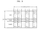
- FIG. 3 is a diagram illustrating a structure of an address unit included in data recorded on an optical recording medium.
- one cluster has 16 address fields, each of which has a capacity of 9 bytes.
- Each of the address fields has 4-byte address unit number (AUN) address information, 1-byte flag information, and 4-byte parity information for the address field.
- AUN address information indicates the address of an ECC cluster among a plurality of ECC clusters.
- the flag information is recorded in the fifth byte of the address field, next to the AUN address information, and is used to record additional information other than location information.
- the flag information can be used to indicate a date and time when data is recorded.
- a parity bit for the address field is recorded in the remaining 4 bytes. This parity bit is for error correction.
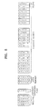
- FIG. 4 is a diagram illustrating a structure of AUN address information according to an embodiment of the present invention.
- Each address field includes 9-byte address information.
- 9-byte address information 4 bytes are allocated to AUN address information, which indicates the address of an ECC cluster among a plurality of ECC clusters. Since 1 byte is composed of 8 bits, the 4-byte information includes 32 bits.
- the high-order 4 bits (i.e., bits 28-31) in the AUN address information are allocated as a reserved area.
- the next 3 bits i.e., 25-27
- the remaining 25 bits i.e., bits 0-24
- the reserved area on a writable or rewritable disk can be used to indicate additional information other than location information.
- the reserved area can be used to indicate state information of defect list entries having a cluster address in which a defect occurs, and a cluster address replacing the defective cluster address.
- the layer information indicates a number of a layer of the recording medium in which the data corresponding to the AUN address information is recorded. As the location of the data corresponding to the AUN address information is expressed by 25 bits, an address space corresponding to 225 can be expressed in each layer. One address is assigned to two user data sectors. Accordingly, the least significant bit (i.e., bit 0) of the AUN address information is fixed as 0.
- FIG. 5 is a diagram illustrating a structure of AUN address information according to another embodiment of the present invention.
- 4 bytes i.e., 32 bits
- the high-order 4 bits i.e., bits 28-31) are allocated as a reserved area
- the next bit i.e., bit 27
- the next 3 bits i.e., bits 24-26
- the remaining 24 bits i.e., bits 0-23
- the reserved area can be used to include additional information other than location information on a writable and rewritable disk (such as included in the reserved area illustrated in FIG. 4 ).
- the reserved area may be used to store state information of defect list entries having a cluster address in which a defect occurs, and a cluster address replacing the defective cluster address.
- the capacity expansion area can be used to record a location of data when locations of data corresponding to the AUN address information cannot be expressed by the remaining 24 bits allocated to indicate the location of the data.
- the capacity expansion area is used to thereby record addresses of the space corresponding to 225.
- the least significant bit (i.e., bit 0) of the AUN address information is fixed as 0.
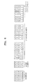
- FIG. 6 is a diagram illustrating a structure of AUN address information, according to yet another embodiment of the present invention.
- 32 bits are allocated to the AUN address information according to the current embodiment of the present invention.
- the high-order 5 bits i.e., bits 27-31) are allocated as a reserved area
- the next 3 bits i.e., bits 24-26
- the next 24 bits i.e., bits 0-23
- the reserved area can be used to store state information of defect list entries having a cluster address in which a defect occurs, and a cluster address replacing the defective cluster address.
- the least significant bit is used as a flag to indicate one of two separate areas in which data is recorded.
- the flag is set to 0 for a first area, and 1 for a second area. Therefore, the location in which data is recorded can be determined as the first area or the second area.
- an address 00 may be assigned to addresses 00 and 01
- an address 10 may be assigned to addresses 10, and 11. That is, since one address is assigned to two sectors, the least significant bit is always 0. However, by using the least significant bit, two areas are distinguished. If the bit is 0, it is determined that the location in which data is recorded is the first area, and if the bit is 1, it is determined that the location in which data is recorded is the second area. In this way, the area in which data is recorded can be determined.
- the location of the data corresponding to the AUN is expressed by 24 bits, and by using the least significant bit of the 24 bits, two areas can be distinguished and addresses of a space corresponding to 224 * 2 can be expressed in each layer.
- FIG. 7 is a flowchart illustrating a method of reproducing data on a recording medium according to an embodiment of the present invention. Referring to FIG. 7 , an optical head unit is moved to a target position of the recording medium corresponding to address information in operation 710.
- one address field includes 32-bit AUN address information.
- the high-order 4 bits are allocated as a reserved area, the next 3 bits indicate layer information on a layer in which data corresponding to the AUN address information is recorded, and the remaining 25 bits indicate the location of the data corresponding to the AUN address information, as illustrated in FIG. 4 .
- the high-order 4 bits of the 32-bit AUN address information are allocated as a reserved area, the next bit is allocated as a capacity expansion area, the next 3 bits indicate layer information on a layer in which data corresponding to the AUN address information is recorded, and the remaining 24 bits indicate the location of the data corresponding to the AUN address information, as illustrated in FIG. 5 .
- the high-order 5 bits of the 32-bit AUN address information are allocated as a reserved area, the next 3 bits indicate layer information on a layer in which data corresponding to the AUN address information is recorded, and the remaining 24 bits indicate the location of the data corresponding to the AUN address information, as illustrated in FIG. 6 .
- Addresses are allocated in the 24 bits indicating the location of data such that the least significant bit is used as a flag to determine one of two separate areas in which data is recorded.
- FIG. 8 is a flowchart illustrating a method of recording data on a recording medium according to an embodiment of the present invention. Referring to FIG. 8 , data and a cluster in which an address indicating the location of data are generated in operation 810. In one cluster, 16 address fields are included.
- one address field includes 32-bit AUN address information.
- the high-order 4 bits are allocated as a reserved area, the next 3 bits indicate layer information on a layer in which data corresponding to the AUN address information is recorded, and the remaining 25 bits indicate the location of the data corresponding to the AUN address information, as illustrated in FIG. 4 .
- the high-order 4 bits of the 32-bit AUN address information are allocated as a reserved area, the next bit is allocated as a capacity expansion area, the next 3 bits indicate layer information on a layer in which data corresponding to the AUN address information is recorded, and the remaining 24 bits indicate the location of the data corresponding to the AUN address information, as illustrated in FIG. 5 .
- the high-order 5 bits of the 32-bit AUN address information are allocated as a reserved area, the next 3 bits indicate layer information on a layer in which data corresponding to the AUN address information is recorded, and the remaining 24 bits indicate the location of the data corresponding to the AUN address information, as illustrated in FIG. 6 .
- Addresses are allocated in the 24 bits indicating the location of the data corresponding to the AUN address information such that the least significant bit is used as a flag to determine one of two separate areas in which data is recorded.
- the generated cluster is recorded on the recording medium in operation 820.
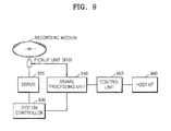
- FIG. 9 is a block diagram illustrating an apparatus for recording and/or reproducing data on a recording medium according to an embodiment of the present invention.
- the apparatus for recording and/or reproducing data on a recording medium includes a pickup unit 910, a servo 920, a system controller 930, a signal processing unit 940, a control unit 950, and a host interface unit 960.
- the pickup unit 910 reproduces data and other information recorded on a recording medium.
- the servo 920 controls the operation of the pickup unit 910.
- the signal processing unit 940 restores a reproduction signal received from the pickup unit 910 to a desired signal value, or modulates the signal into a signal that is to be recorded on a recording medium and transfers the modulated signal.
- the host interface unit 960 receives a command from a host to record or reproduce a data structure, transfers the command to the control unit 950, and receives data from the control unit 950.
- the control unit 950 includes an encoder and a decoder (both not shown).
- the decoder decodes a signal read from a recording medium, and provides the decoded signal to a host.
- the encoder converts an input signal to a signal of a predetermined format determined by the control unit 950, and transfers the converted signal to the signal processing unit 940 so that the signal can be recorded on the recording medium.
- control unit 950 controls the signal processing unit 940 to generate an ECC cluster in which addresses and data are recorded. Then the pickup unit 910 records the generated ECC cluster on the recording medium.
- the signal processing unit 940 assigns addresses to 16 address fields included in each cluster.
- one address field includes 32-bit AUN address information.
- the high-order 4 bits are allocated as a reserved area, the next 3 bits indicate layer information on a layer in which data corresponding to the AUN address information is recorded, and the remaining 25 bits indicate the location of the data corresponding to the AUN address information, as illustrated in FIG. 4 .
- the high-order 4 bits of the 32-bit AUN address information are allocated as a reserved area, the next bit is allocated as a capacity expansion area, the next 3 bits indicate layer information on a layer in which data corresponding to the AUN address information is recorded, and the remaining 24 bits indicate the location of the data corresponding to the AUN address information, as illustrated in FIG. 5 .
- the high-order 5 bits of the 32-bit AUN address information are allocated as a reserved area, the next 3 bits indicate layer information on a layer in which data corresponding to the AUN address information is recorded, and the remaining 24 bits indicate the location of the data corresponding to the AUN address information, as illustrated in FIG. 6 .
- Addresses are allocated in the 24 bits indicating the location of data such that the least significant bit is used as a flag to determine one of two separate areas in which data is recorded.
- a space in which addresses are recorded can be expanded, thereby securing an address area in which addresses of data in a data structure can be recorded. Also, data at a predetermined location can be accurately reproduced, and identification of a location can be quickly performed through a hierarchical structure of layer numbers and sequence numbers.
Landscapes
- Engineering & Computer Science (AREA)
- Signal Processing (AREA)
- Signal Processing For Digital Recording And Reproducing (AREA)
- Indexing, Searching, Synchronizing, And The Amount Of Synchronization Travel Of Record Carriers (AREA)
- Management Or Editing Of Information On Record Carriers (AREA)
Applications Claiming Priority (2)
| Application Number | Priority Date | Filing Date | Title |
|---|---|---|---|
| KR1020060113903A KR20080045002A (ko) | 2006-11-17 | 2006-11-17 | 기록 매체, 재생 장치 및 재생 방법, 기록 장치 및 기록방법 |
| EP07834028A EP2092519A4 (en) | 2006-11-17 | 2007-11-15 | RECORDING MEDIUM, METHOD AND DEVICE FOR REPRODUCING DATA ON THE RECORDING MEDIUM AND METHOD AND DEVICE FOR RECORDING DATA ON THE RECORDING MEDIUM |
Related Parent Applications (1)
| Application Number | Title | Priority Date | Filing Date |
|---|---|---|---|
| EP07834028.8 Division | 2007-11-15 |
Publications (1)
| Publication Number | Publication Date |
|---|---|
| EP2369584A1 true EP2369584A1 (en) | 2011-09-28 |
Family
ID=39401866
Family Applications (2)
| Application Number | Title | Priority Date | Filing Date |
|---|---|---|---|
| EP11169366A Withdrawn EP2369584A1 (en) | 2006-11-17 | 2007-11-15 | Recording medium, method and apparatus for reproducing data on the recording medium, and method and apparatus for recording data on the recording medium |
| EP07834028A Withdrawn EP2092519A4 (en) | 2006-11-17 | 2007-11-15 | RECORDING MEDIUM, METHOD AND DEVICE FOR REPRODUCING DATA ON THE RECORDING MEDIUM AND METHOD AND DEVICE FOR RECORDING DATA ON THE RECORDING MEDIUM |
Family Applications After (1)
| Application Number | Title | Priority Date | Filing Date |
|---|---|---|---|
| EP07834028A Withdrawn EP2092519A4 (en) | 2006-11-17 | 2007-11-15 | RECORDING MEDIUM, METHOD AND DEVICE FOR REPRODUCING DATA ON THE RECORDING MEDIUM AND METHOD AND DEVICE FOR RECORDING DATA ON THE RECORDING MEDIUM |
Country Status (9)
Families Citing this family (11)
| Publication number | Priority date | Publication date | Assignee | Title |
|---|---|---|---|---|
| TWI400700B (zh) * | 2004-05-11 | 2013-07-01 | 松下電器產業股份有限公司 | Information recording device |
| KR20080045002A (ko) * | 2006-11-17 | 2008-05-22 | 삼성전자주식회사 | 기록 매체, 재생 장치 및 재생 방법, 기록 장치 및 기록방법 |
| US7830753B2 (en) * | 2007-11-20 | 2010-11-09 | Panasonic Corporation | Optical disc, optical disc drive, optical disc recording/reproducing method, and integrated circuit |
| JP5070231B2 (ja) * | 2009-02-12 | 2012-11-07 | 株式会社日立製作所 | 記録媒体、アドレス生成及び検出方法、再生及び記録装置 |
| JP5011326B2 (ja) * | 2009-02-24 | 2012-08-29 | 株式会社日立製作所 | 情報記録媒体、アドレス生成及び検出方法、再生及び記録装置 |
| JP5018804B2 (ja) * | 2009-02-24 | 2012-09-05 | 株式会社日立製作所 | アドレス生成及び検出方法、再生及び記録装置 |
| KR102041093B1 (ko) | 2011-04-11 | 2019-11-06 | 크라운 이큅먼트 코포레이션 | 조정된 경로 계획기를 사용하는 다수의 자동화 비-홀로노믹 차량들을 효율적으로 스케줄링하는 방법 및 장치 |
| US20140058634A1 (en) | 2012-08-24 | 2014-02-27 | Crown Equipment Limited | Method and apparatus for using unique landmarks to locate industrial vehicles at start-up |
| US9056754B2 (en) | 2011-09-07 | 2015-06-16 | Crown Equipment Limited | Method and apparatus for using pre-positioned objects to localize an industrial vehicle |
| JP5544389B2 (ja) * | 2012-04-16 | 2014-07-09 | 日立コンシューマエレクトロニクス株式会社 | アドレス生成及び検出方法、再生及び記録装置 |
| JP2012256420A (ja) * | 2012-08-10 | 2012-12-27 | Hitachi Ltd | 記録媒体、アドレス生成及び検出方法、再生及び記録装置 |
Citations (7)
| Publication number | Priority date | Publication date | Assignee | Title |
|---|---|---|---|---|
| US20020194568A1 (en) * | 2000-01-07 | 2002-12-19 | Yoshiharu Kobayashi | Error correcting method, disk medium, disk recording method and disk reproducing method |
| EP1435607A1 (en) * | 2001-10-09 | 2004-07-07 | Sony Corporation | Disc recording medium, disc drive apparatus, reproduction method, and disc manufacturing method |
| WO2004086403A1 (en) * | 2003-03-24 | 2004-10-07 | Koninklijke Philips Electronics N.V. | Multilayer optical disc having a layer indication |
| US20050210045A1 (en) * | 2004-03-19 | 2005-09-22 | Park Yong C | Data structure recorded in a recording medium data recording method and data recording apparatus |
| WO2006061736A1 (en) * | 2004-12-08 | 2006-06-15 | Koninklijke Philips Electronics N.V. | Extending the addressing space of record carriers |
| WO2006061727A1 (en) * | 2004-12-07 | 2006-06-15 | Koninklijke Philips Electronics N.V. | Addressing disc storage space using head position |
| KR20060113903A (ko) | 2006-04-27 | 2006-11-03 | 가부시키가이샤 아네모스 | 산기 처리 장치 |
Family Cites Families (14)
| Publication number | Priority date | Publication date | Assignee | Title |
|---|---|---|---|---|
| JP2001006293A (ja) * | 1999-06-16 | 2001-01-12 | Sony Corp | ディスク記録媒体、及びディスクドライブ装置 |
| AU2001282543B2 (en) * | 2000-08-31 | 2005-03-17 | Matsushita Electric Industrial Co., Ltd. | Optical disc and physical address format |
| EP1509917A4 (en) * | 2002-06-05 | 2009-12-02 | Lg Electronics Inc | STRUCTURE OF BONDING AREA FORMED ON HIGH-DENSITY NON-INDEPENDENT RECORDING MEDIUM AND METHOD OF MANUFACTURING / REPRODUCING SAME, AND APPARATUS HAVING THE SAME |
| EP1870892A3 (en) * | 2002-06-05 | 2010-02-17 | LG Electronics, Inc. | Computer-readable read-only storage medium and method and apparatus for reproducing data recorded thereon |
| CA2537895A1 (en) * | 2003-09-08 | 2005-03-17 | Lg Electronics Inc. | Write-once optical disc, and method and apparatus for recording management information thereon |
| JP2005085445A (ja) * | 2003-09-11 | 2005-03-31 | Pioneer Electronic Corp | 情報記録媒体、情報記録再生装置及び情報記録再生方法 |
| US7970988B2 (en) * | 2004-03-19 | 2011-06-28 | Lg Electronics Inc. | Recording medium with status information thereon which changes upon reformatting and apparatus and methods for forming, recording, and reproducing the recording medium |
| JP5144265B2 (ja) * | 2004-09-14 | 2013-02-13 | エルジー エレクトロニクス インコーポレイティド | 記録媒体及び記録媒体の記録再生方法及び装置 |
| JP2007042152A (ja) * | 2005-07-29 | 2007-02-15 | Toshiba Corp | 追記形情報記憶媒体(透明基板上に形成された記録層を内側にして接着された構造を持つ記録形情報記憶媒体のディスク構造)、および情報再生方法または情報記録方法ならびに記憶媒体製造装置 |
| JP2007080367A (ja) * | 2005-09-13 | 2007-03-29 | Toshiba Corp | 情報記憶媒体、情報記録方法、および情報再生装置 |
| KR100596319B1 (ko) | 2005-09-27 | 2006-07-03 | 엘지전자 주식회사 | 고밀도 재생 전용 광디스크의 링킹 영역 데이터기록방법과, 그에 따른 고밀도 재생 전용 광디스크 |
| JP2007234204A (ja) * | 2006-01-31 | 2007-09-13 | Toshiba Corp | 情報記憶媒体、情報記録方法および情報記録装置 |
| JP2009529443A (ja) | 2006-03-09 | 2009-08-20 | イー・アイ・デュポン・ドウ・ヌムール・アンド・カンパニー | インクジェットインクセット |
| KR20080045002A (ko) * | 2006-11-17 | 2008-05-22 | 삼성전자주식회사 | 기록 매체, 재생 장치 및 재생 방법, 기록 장치 및 기록방법 |
-
2006
- 2006-11-17 KR KR1020060113903A patent/KR20080045002A/ko not_active Ceased
-
2007
- 2007-11-15 AU AU2007320210A patent/AU2007320210B2/en not_active Ceased
- 2007-11-15 EP EP11169366A patent/EP2369584A1/en not_active Withdrawn
- 2007-11-15 JP JP2009537080A patent/JP2010510610A/ja active Pending
- 2007-11-15 MX MX2009005225A patent/MX2009005225A/es active IP Right Grant
- 2007-11-15 MY MYPI20091842A patent/MY143932A/en unknown
- 2007-11-15 US US11/940,452 patent/US7738353B2/en active Active
- 2007-11-15 EP EP07834028A patent/EP2092519A4/en not_active Withdrawn
- 2007-11-15 MY MYPI2011000859A patent/MY149080A/en unknown
- 2007-11-15 WO PCT/KR2007/005721 patent/WO2008060103A1/en active Application Filing
- 2007-11-15 CN CN201110220009XA patent/CN102290062A/zh active Pending
- 2007-11-15 CN CN2007800425616A patent/CN101542613B/zh not_active Expired - Fee Related
-
2010
- 2010-06-13 US US12/814,471 patent/US7881177B2/en active Active
- 2010-12-20 US US12/973,025 patent/US8295149B2/en not_active Expired - Fee Related
Patent Citations (7)
| Publication number | Priority date | Publication date | Assignee | Title |
|---|---|---|---|---|
| US20020194568A1 (en) * | 2000-01-07 | 2002-12-19 | Yoshiharu Kobayashi | Error correcting method, disk medium, disk recording method and disk reproducing method |
| EP1435607A1 (en) * | 2001-10-09 | 2004-07-07 | Sony Corporation | Disc recording medium, disc drive apparatus, reproduction method, and disc manufacturing method |
| WO2004086403A1 (en) * | 2003-03-24 | 2004-10-07 | Koninklijke Philips Electronics N.V. | Multilayer optical disc having a layer indication |
| US20050210045A1 (en) * | 2004-03-19 | 2005-09-22 | Park Yong C | Data structure recorded in a recording medium data recording method and data recording apparatus |
| WO2006061727A1 (en) * | 2004-12-07 | 2006-06-15 | Koninklijke Philips Electronics N.V. | Addressing disc storage space using head position |
| WO2006061736A1 (en) * | 2004-12-08 | 2006-06-15 | Koninklijke Philips Electronics N.V. | Extending the addressing space of record carriers |
| KR20060113903A (ko) | 2006-04-27 | 2006-11-03 | 가부시키가이샤 아네모스 | 산기 처리 장치 |
Also Published As
| Publication number | Publication date |
|---|---|
| US20110085426A1 (en) | 2011-04-14 |
| AU2007320210B2 (en) | 2011-03-31 |
| US7881177B2 (en) | 2011-02-01 |
| US20080117793A1 (en) | 2008-05-22 |
| MY149080A (en) | 2013-07-15 |
| US7738353B2 (en) | 2010-06-15 |
| CN101542613B (zh) | 2012-01-11 |
| US20100296372A1 (en) | 2010-11-25 |
| KR20080045002A (ko) | 2008-05-22 |
| US8295149B2 (en) | 2012-10-23 |
| CN102290062A (zh) | 2011-12-21 |
| AU2007320210A1 (en) | 2008-05-22 |
| JP2010510610A (ja) | 2010-04-02 |
| CN101542613A (zh) | 2009-09-23 |
| MX2009005225A (es) | 2009-05-28 |
| EP2092519A4 (en) | 2010-10-20 |
| MY143932A (en) | 2011-07-29 |
| EP2092519A1 (en) | 2009-08-26 |
| WO2008060103A1 (en) | 2008-05-22 |
Similar Documents
| Publication | Publication Date | Title |
|---|---|---|
| US7738353B2 (en) | Recording medium, method and apparatus for reproducing data on the recording medium, and method and apparatus for recording data on the recording medium | |
| US8572464B2 (en) | Recording and/or reproducing method, recording and/or reproducing apparatus, and computer readable recording medium storing program for performing the method | |
| US20100100694A1 (en) | Recording/reproducing apparatus for performing rmw for low, recording/reproducing method therefor, and information storage medium therefor | |
| JP4955819B2 (ja) | 光記録情報保存媒体、記録/再生方法、記録/再生装置、及びその方法を行うプログラムが記録されたコンピュータ読み取り可能な記録媒体 | |
| JP4262611B2 (ja) | データ記録方法、及びデータ記録装置 | |
| US20080192597A1 (en) | Information storage medium, recording/reproducing apparatus, and recording/reproducing method | |
| JP2007502512A (ja) | パディング情報を利用した記録/再生方法、その記録/再生装置及びその情報記録媒体 | |
| JP4769881B2 (ja) | デジタルデータ記録方法、記録装置及び再生装置 | |
| JP4713140B2 (ja) | デジタルデータ記録方法、記録装置及び再生装置 | |
| KR101113866B1 (ko) | 기록매체내에 기록되는 데이터 구조 및 데이터 기록방법과기록장치 | |
| JP2006040454A (ja) | 追記型光ディスク装置 | |
| JP2007035195A (ja) | 情報記憶媒体、情報記録再生装置、および情報記録再生方法 | |
| HK1108216B (en) | Information storage medium, recording/reproducing apparatus, and recording/reproducing method |
Legal Events
| Date | Code | Title | Description |
|---|---|---|---|
| PUAI | Public reference made under article 153(3) epc to a published international application that has entered the european phase |
Free format text: ORIGINAL CODE: 0009012 |
|
| AC | Divisional application: reference to earlier application |
Ref document number: 2092519 Country of ref document: EP Kind code of ref document: P |
|
| AK | Designated contracting states |
Kind code of ref document: A1 Designated state(s): AT BE BG CH CY CZ DE DK EE ES FI FR GB GR HU IE IS IT LI LT LU LV MC MT NL PL PT RO SE SI SK TR |
|
| STAA | Information on the status of an ep patent application or granted ep patent |
Free format text: STATUS: THE APPLICATION IS DEEMED TO BE WITHDRAWN |
|
| RAP1 | Party data changed (applicant data changed or rights of an application transferred) |
Owner name: SAMSUNG ELECTRONICS CO., LTD. |
|
| 18D | Application deemed to be withdrawn |
Effective date: 20120329 |