EP2368478A2 - Dishwasher - Google Patents
Dishwasher Download PDFInfo
- Publication number
- EP2368478A2 EP2368478A2 EP11156165A EP11156165A EP2368478A2 EP 2368478 A2 EP2368478 A2 EP 2368478A2 EP 11156165 A EP11156165 A EP 11156165A EP 11156165 A EP11156165 A EP 11156165A EP 2368478 A2 EP2368478 A2 EP 2368478A2
- Authority
- EP
- European Patent Office
- Prior art keywords
- supply line
- dishwasher according
- dishwasher
- container
- washing
- Prior art date
- Legal status (The legal status is an assumption and is not a legal conclusion. Google has not performed a legal analysis and makes no representation as to the accuracy of the status listed.)
- Granted
Links
- 238000005406 washing Methods 0.000 claims abstract description 59
- XLYOFNOQVPJJNP-UHFFFAOYSA-N water Substances O XLYOFNOQVPJJNP-UHFFFAOYSA-N 0.000 claims abstract description 43
- 238000011049 filling Methods 0.000 claims abstract description 8
- 230000000903 blocking effect Effects 0.000 claims description 12
- 230000001172 regenerating effect Effects 0.000 claims description 12
- 239000007788 liquid Substances 0.000 claims description 11
- 150000003839 salts Chemical class 0.000 claims description 10
- 230000005484 gravity Effects 0.000 claims description 6
- 239000003795 chemical substances by application Substances 0.000 claims description 4
- 238000007789 sealing Methods 0.000 description 9
- 238000005342 ion exchange Methods 0.000 description 8
- 239000000945 filler Substances 0.000 description 4
- 239000012492 regenerant Substances 0.000 description 4
- 239000007921 spray Substances 0.000 description 4
- 239000012267 brine Substances 0.000 description 2
- 238000004140 cleaning Methods 0.000 description 2
- 238000001035 drying Methods 0.000 description 2
- 238000011010 flushing procedure Methods 0.000 description 2
- 239000012535 impurity Substances 0.000 description 2
- 230000007257 malfunction Effects 0.000 description 2
- 238000012986 modification Methods 0.000 description 2
- 230000004048 modification Effects 0.000 description 2
- HPALAKNZSZLMCH-UHFFFAOYSA-M sodium;chloride;hydrate Chemical compound O.[Na+].[Cl-] HPALAKNZSZLMCH-UHFFFAOYSA-M 0.000 description 2
- 238000005507 spraying Methods 0.000 description 2
- 238000010276 construction Methods 0.000 description 1
- 238000011109 contamination Methods 0.000 description 1
- 230000007547 defect Effects 0.000 description 1
- 238000010586 diagram Methods 0.000 description 1
- 238000004851 dishwashing Methods 0.000 description 1
- 238000009434 installation Methods 0.000 description 1
- 238000011068 loading method Methods 0.000 description 1
- 230000014759 maintenance of location Effects 0.000 description 1
- 238000004519 manufacturing process Methods 0.000 description 1
- 239000000463 material Substances 0.000 description 1
- 238000000034 method Methods 0.000 description 1
- 230000008929 regeneration Effects 0.000 description 1
- 238000011069 regeneration method Methods 0.000 description 1
- 239000008234 soft water Substances 0.000 description 1
- 238000003860 storage Methods 0.000 description 1
Images

Classifications
-
- A—HUMAN NECESSITIES
- A47—FURNITURE; DOMESTIC ARTICLES OR APPLIANCES; COFFEE MILLS; SPICE MILLS; SUCTION CLEANERS IN GENERAL
- A47L—DOMESTIC WASHING OR CLEANING; SUCTION CLEANERS IN GENERAL
- A47L15/00—Washing or rinsing machines for crockery or tableware
- A47L15/42—Details
- A47L15/4214—Water supply, recirculation or discharge arrangements; Devices therefor
- A47L15/4217—Fittings for water supply, e.g. valves or plumbing means to connect to cold or warm water lines, aquastops
-
- A—HUMAN NECESSITIES
- A47—FURNITURE; DOMESTIC ARTICLES OR APPLIANCES; COFFEE MILLS; SPICE MILLS; SUCTION CLEANERS IN GENERAL
- A47L—DOMESTIC WASHING OR CLEANING; SUCTION CLEANERS IN GENERAL
- A47L15/00—Washing or rinsing machines for crockery or tableware
- A47L15/42—Details
- A47L15/4229—Water softening arrangements
- A47L15/4231—Constructional details of the salt container or the ion exchanger
-
- A—HUMAN NECESSITIES
- A47—FURNITURE; DOMESTIC ARTICLES OR APPLIANCES; COFFEE MILLS; SPICE MILLS; SUCTION CLEANERS IN GENERAL
- A47L—DOMESTIC WASHING OR CLEANING; SUCTION CLEANERS IN GENERAL
- A47L15/00—Washing or rinsing machines for crockery or tableware
- A47L15/42—Details
- A47L15/4246—Details of the tub
-
- A—HUMAN NECESSITIES
- A47—FURNITURE; DOMESTIC ARTICLES OR APPLIANCES; COFFEE MILLS; SPICE MILLS; SUCTION CLEANERS IN GENERAL
- A47L—DOMESTIC WASHING OR CLEANING; SUCTION CLEANERS IN GENERAL
- A47L15/00—Washing or rinsing machines for crockery or tableware
- A47L15/42—Details
- A47L15/4291—Recovery arrangements, e.g. for the recovery of energy or water
Definitions
- the invention relates to a dishwasher, in particular a domestic dishwasher, at least one washing container for receiving items to be cleaned and / or to be dried and having a supply line for conducting water in the washing container, wherein the outlet end of the supply line is arranged above the Tropllindis the dishwasher ,
- Dishwashers in particular household dishwashers, have a rinsing container in which items to be cleaned can be stored in dish racks which can be pulled out of the rinsing container, wherein the rinsing container can be opened or closed by means of a door for loading and / or unloading the racks.
- water can be passed into the washing container.
- a supply line is provided, whose end is guided through a passage opening in a side wall of the washing container of the dishwasher and can be passed through the water from a home-side supply system or a water tank of the dishwasher in the washing.
- the passage opening is arranged so that it is above a Basic Glands that results when the dishwasher with a for operation, d. H. for cleaning and / or drying of items to be washed, provided amount of water is filled.
- this arrangement reliably prevents contaminated water from passing through the passage opening into the supply line, this arrangement has a particularly long line length due to the lateral high guidance, which increases the water consumption due to the dead volume of the supply line.
- a container opening for passing through the feed line through a wall of the washing container is arranged below an operating filling level of the dishwasher.
- a supply line for supplying a softening device for softening water with at least one regenerating agent, in particular regenerating salt runs through the container opening.
- a softening device of the dishwasher To reduce the water hardness of the water fed into the washing container, the water passes through the softening device of the dishwasher before it is filled.
- a softening device requires as a resource a regenerating agent, in particular a regenerating salt.
- the supply line is provided, which extends through the wall of the washing compartment in the interior of the washing compartment, and by means of which the softening unit can be supplied with regenerating salt, if necessary. Since this opening is arranged in the interior of the washing container, an opening of the washing container is therefore required for refilling. By arranging the manufacturing cost is reduced, since it is only necessary to introduce a passage opening in the washing, to seal and finally to verify.
- the retaining means are arranged on a cover which closes the end of the supply line.
- the lid is used to close the line, with the softening regenerating salt can be supplied if necessary and ensures during normal operation of the dishwasher that no liquid can pass through the feed undesirably in the softening device.
- the cover may have a threaded portion which cooperates with a corresponding portion in the washing container, with which the lid can be attached by a rotary movement and also released again.
- a bayonet catch can be provided.
- the supply line at least one retaining means for blocking a directed from the washing container Liquid flow is assigned.
- the retaining means can be, for example, spray water that bounces off the items to be washed during operation of the dishwasher or, in the case of a blockage-related malfunction, a quantity of liquid collecting on the bottom of the washing container which penetrates into the open end of the second line inside the washing container.
- the retaining means are associated with the lid. This allows in the case of a defect of the retaining means this easy to replace with the lid.
- the retaining means is designed as a check valve.
- the check valve is arranged such that it allows a liquid flow to pass into the washing, while blocking a flow of liquid out of the washing out.
- the retaining means have an outlet end of the second conduit formed as an overflow.
- the outlet opening of the supply line before entering spray water is preferably provided that the cover covers the overflow.
- the retaining means are arranged at the end of the second conduit. This means that the retention means are located inside the washing container and thus ensures that no unwanted liquid residues remain in a liquid section. Furthermore, it is ensured in this case that the retaining means without the installation of the dishwasher can be achieved simply by opening the rinse tank to correct any malfunctions.
- the supply line and the supply line at least in sections, in particular in the passage area in the washing, d. H. when passing through the Spül hereerwandung, are arranged parallel to each other.
- the portion of the first conduit and the second conduit may extend from the softening device into the interior of the washing compartment.
- the supply line and the supply line at least in sections, in particular in the passage area in the washing, d. H. when passing through the Spül hereerwandung, are arranged concentrically to each other. This allows a particularly space-saving, compact design.
- the supply line and the supply line at least in sections, in particular in the passage area in the washing, d. H. when passing through the Spül hereerwandung, are arranged running in the direction of gravity. This ensures that regenerating salt can be fed to the softening device, in particular through the supply line for supplying the softening device by gravity, without the need for additional aids.
- the container opening is arranged in the bottom of the washing compartment.
- the container opening may also be arranged in the region of a side wall of the washing container.
- the softening device is arranged below the washing compartment. This also allows a particularly compact embodiment with low space requirement, which is ensured by the arrangement of the softening device and the rinsing container that the regenerating salt can reach the softening device automatically by gravity.
- the check valve has a displaceable blocking body, which closes the supply line due to gravity or is pressed into its closed position by means of a spring element. With this simple mechanical construction, a reliable function is achieved.
- the blocking body can be displaceable in a connecting piece of the cover in the axial direction between a closed position and a release position.
- the connecting piece of the lid can connect the inlet fluidically with the washing compartment.
- the connecting channel of the lid sealingly protrude into the inlet.
- the blocking body can be brought in a closed position with a sealing surface into contact with a corresponding sealing surface of the lid. As soon as water is introduced into the washing container, the blocking body is lifted by the inflowing water from its closed position into a release position, in which the water can run into the washing compartment through an annular gap formed between the blocking body and the lid.
- the lifting movement of the locking body in the release position may be limited by a movement stop.
- the movement stop can engage behind the connection piece of the cover on the end facing away from the sealing surfaces of the blocking body. In this way, the locking body is held captive on the lid even when unscrewed from Regenerierstoff necessarilyer lid of the locking body.
- the inlet can be connected with the interposition of a labyrinth seal with the washing compartment of the washing.
- a labyrinth seal By means of the labyrinth seal, as with the filling valve, clogging of the feed with impurities can be prevented.
- the labyrinth seal can be connected downstream of the inlet and be provided by way of example by a correspondingly adapted cover geometry.
- the inlet can project without contact into a free space of the lid.
- the lid can have a free flow gap be spaced from the Spül electergeber through which the water from the lid-free space can flow into the washing compartment.
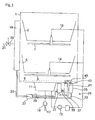
- Fig. 1 is shown as an exemplary embodiment of a dishwasher, a household dishwasher with a, a washing compartment delimiting washing container 1.
- a washing compartment delimiting washing container 1 In the washing compartment of the washing container 1, not to be cleaned, to be cleaned dishes in dish racks 3, 5 are arranged.
- two spraying arms 7, 8 provided in different spraying levels are arranged by way of example, via which the washware to be cleaned is supplied with washing liquid.
- a pump pot 11 is provided with associated circulating pump 13, which is connected via feed lines 14, 15 fluidly connected to the spray arms 7, 8.
- the pump pot 11 is connected via a drain line 17 with therein provided drain pump 18 with a haus workedem sewer system.
- the softening device 25 is preceded by a switching valve 27, which is connected via a first connecting line 29 directly to the ion exchange container 31 of the softening device 25 and is connected to the regenerating agent tank 35 of the softening device 25 by a second connecting line 33.
- the regenerant tank 35 is connected via an intermediate line 37 to the ion exchange container 31, wherein in the intermediate line 37 a in the present embodiment designed as a check valve filling valve 39 is connected, which blocks a water return from the ion exchange container 31 in the Regenerierstoffspiel whatsoever35.
- the water from the water supply network via a filling valve 39 into the heat exchanger 19 and from there via the switching valve 27 and the first connecting line 29 is passed directly through the ion exchange container 31, in which the water is softened. Subsequently, the thus softened soft water flows through an overflow in a supply line 41 into the washing compartment.
- a regeneration process takes place in which the water is first conducted via the switching valve 27 and the second connecting line 33 into the regenerant tank 35, which usually contains salt.
- the brine formed thereby is further passed via the intermediate conduit 37 into the ion exchange vessel 31 in which the ion exchange between the brine and the ion exchange material takes place.
- the regenerant container 27 can according to the Fig. 1 be filled on the user side with salt via a filler neck of the supply line 43. The filler neck is closed by means of a lid 45.
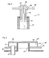
- the supply line 41 is in accordance with the Fig. 2 directly guided by the Regenerierstoff investigating mechanism 35 and coaxially to the supply line 43, wherein in the present embodiment, the end of the supply line 43 is formed as a filler neck.
- a threaded sleeve 49 is formed with an internal thread on the cover 45, which is screwed onto an external thread of the filler neck. Radially outside the threaded sleeve 49 of the lid 45 is surrounded by an annular wall 51. Radially within the threaded sleeve 49, a central connecting piece 53 is integrally formed, which projects into the upper end of the feed line 41.
- a mouth opening of the connection piece 53 facing the flushing space is surrounded by an annular stepped valve seat 55 on which a sealing disk 57 of a blocking body 59 is seated in a form-fitting and sealing manner.
- the locking body 59 is according to the Fig. 2 passed through the connecting piece 53 and has at its lower end latching lugs 61 with expanded diameter, which engage behind the connecting piece 53 with axial distance.
- valve seat 55 is a groove bottom of a circumferential around the mouth opening of the connecting piece 53 annular groove, on which groove bottom a correspondingly shaped annular web of the sealing washer 57 rests sealingly.
- the locking body 59 is pushed in the flow direction upwards until the locking lugs 61 abut against the lower end face of the connecting piece 53.
- the locking lugs 61 act in this case as a movement stop, which limits the lifting movement of the locking body 59 upwards.
- a modification of the water inlet according to the invention is shown.
- the supply pipe 41 is disposed radially outside the first pipe 43.
- the end of the supply line 41 is in accordance with Fig. 5 Covered by the lid 45, so that clogging of the end of the supply line 41 can be prevented with impurities.
- the end protrudes into an annular recess 63 of the lid 45 a.
- the annular recess 63 is bounded on the outside by the circumferential annular wall 51 in the radial direction and on the inside by the threaded sleeve 49 of the cover 45.
- the Fig. 5 is provided between the lower edge of the annular wall 51 and the Spül electerteil 6, a free flow gap 65 through which the water flowing into the annular space 63 is guided into the washing compartment.
Abstract
Description
Die Erfindung betrifft eine Geschirrspülmaschine, insbesondere eine Haushalts-Geschirrspülmaschine, wenigstens einen Spülbehälter zur Aufnahme von zu reinigenden und/oder zu trocknenden Spülgut und eine Zuführleitung zum Leiten von Wasser in den Spülbehälter aufweisend, wobei das Austrittsende der Zuführleitung oberhalb des Betriebsfüllniveaus der Geschirrspülmaschine angeordnet ist.The invention relates to a dishwasher, in particular a domestic dishwasher, at least one washing container for receiving items to be cleaned and / or to be dried and having a supply line for conducting water in the washing container, wherein the outlet end of the supply line is arranged above the Betriebsfüllniveaus the dishwasher ,
Geschirrspülmaschinen, insbesondere Haushalts-Geschirrspülmaschinen, weisen einen Spülbehälter auf, in dem zu reinigendes Spülgut in aus dem Spülbehälter herausziehbaren Geschirrkörben gelagert werden kann, wobei der Spülbehälter mittels einer Tür zum Be- und/oder Entladen der Geschirrkörbe geöffnet bzw. geschlossen werden kann. Zur Reinigung des in den Geschirrkörben angeordneten Spülguts kann Wasser in den Spülbehälter geleitet werden. Hierzu ist eine Zuführleitung vorgesehen, deren Ende durch eine Durchtrittsöffnung in einer Seitenwand des Spülbehälters der Geschirrspülmaschine geführt ist und durch die Wasser aus einem hausseitigen Versorgungssystem oder einem Wassertank der Geschirrspülmaschine in den Spülbehälter geleitet werden kann. Dabei ist die Durchtrittsöffnung so angeordnet, dass sie oberhalb eines Betriebsfüllniveaus liegt, dass sich ergibt, wenn die Geschirrspülmaschine mit einer zum Betrieb, d. h. zum Reinigen und/oder Trocknen von Spülgut, vorgesehenen Wassermenge gefüllt ist. Durch diese Anordnung wird zwar zuverlässig verhindert, dass verschmutztes Wasser durch die Durchtrittsöffnung in die Zuführleitung gelangen kann, jedoch weist diese Anordnung eine besonders große Leitungslänge aufgrund der seitlichen Hochführung auf, was den Wasserverbrauch aufgrund des Totvolumens der Zuführleitung erhöht.Dishwashers, in particular household dishwashers, have a rinsing container in which items to be cleaned can be stored in dish racks which can be pulled out of the rinsing container, wherein the rinsing container can be opened or closed by means of a door for loading and / or unloading the racks. To clean the items arranged in the dishwashing items, water can be passed into the washing container. For this purpose, a supply line is provided, whose end is guided through a passage opening in a side wall of the washing container of the dishwasher and can be passed through the water from a home-side supply system or a water tank of the dishwasher in the washing. In this case, the passage opening is arranged so that it is above a Betriebsfüllniveaus that results when the dishwasher with a for operation, d. H. for cleaning and / or drying of items to be washed, provided amount of water is filled. Although this arrangement reliably prevents contaminated water from passing through the passage opening into the supply line, this arrangement has a particularly long line length due to the lateral high guidance, which increases the water consumption due to the dead volume of the supply line.
Es ist daher Aufgabe der Erfindung, eine Geschirrspülmaschine mit einem reduzierten Wasserverbrauch bereitzustellen.It is therefore an object of the invention to provide a dishwasher with a reduced water consumption.
Erfindungsgemäß ist vorgesehen, dass eine Behälteröffnung zum Durchführen der Zuführleitung durch eine Wandung des Spülbehälters unterhalb eines Betriebsfüllniveaus der Geschirrspülmaschine angeordnet ist. Durch diese Anordnung kann die Zuführleitung in ihrer Länge deutlich reduziert werden, was das Totvolumen reduziert, wobei durch die Anordnung der Behälteröffnung oberhalb des Betriebsfüllniveaus, dass sich einstellt, wenn die Geschirrspülmaschine mit einer für den bestimmungsgemäßen Gebrauch erforderlichen Wassermenge befüllt ist, sichergestellt ist, dass es zu keiner Verschmutzung der Zuführleitung kommt.According to the invention, it is provided that a container opening for passing through the feed line through a wall of the washing container is arranged below an operating filling level of the dishwasher. By this arrangement, the supply line be significantly reduced in length, which reduces the dead volume, which is ensured by the arrangement of the container opening above the Betriebsfüllniveaus that sets when the dishwasher is filled with a required amount of water for the intended use, that there is no contamination of the supply comes.
Vorzugsweise ist vorgesehen, dass durch die Behälteröffnung eine Versorgungsleitung zur Versorgung einer Enthärtungseinrichtung zum Enthärten von Wasser mit wenigstens einem Regeneriermittel, insbesondere Regeneriersalz, verläuft. Zur Reduzierung der Wasserhärte des in den Spülbehälter geleiteten Wassers durchläuft das Wasser vor dem Einfüllen die Enthärtungseinrichtung der Geschirrspülmaschine. Eine derartige Enthärtungseinrichtung benötigt als Betriebsmittel ein Regeneriermittel, insbesondere ein Regeneriersalz. Zum Nachfüllen des Regeneriersalz ist die Versorgungsleitung vorgesehen, die sich durch der Wandung des Spülbehälters in des Innere des Spülbehälters erstreckt, und durch die die Enthärtungseinrichtung mit Regeneriersalz im Bedarfsfall versorgt werden kann. Da diese Öffnung im Inneren des Spülbehälters angeordnet ist, ist daher zum Nachfüllen ein Öffnen des Spülbehälters erforderlich. Durch die Anordnung wird der Fertigungsaufwand reduziert, da es nur erforderlich ist, eine Durchführungsöffnung in den Spülbehälter einzubringen, diese abzudichten und schließlich zu überprüfen.It is preferably provided that a supply line for supplying a softening device for softening water with at least one regenerating agent, in particular regenerating salt, runs through the container opening. To reduce the water hardness of the water fed into the washing container, the water passes through the softening device of the dishwasher before it is filled. Such a softening device requires as a resource a regenerating agent, in particular a regenerating salt. To refill the regenerating salt, the supply line is provided, which extends through the wall of the washing compartment in the interior of the washing compartment, and by means of which the softening unit can be supplied with regenerating salt, if necessary. Since this opening is arranged in the interior of the washing container, an opening of the washing container is therefore required for refilling. By arranging the manufacturing cost is reduced, since it is only necessary to introduce a passage opening in the washing, to seal and finally to verify.
In einer weiteren Ausführungsform ist vorgesehen, dass die Rückhaltemittel an einem Deckel angeordnet sind, der das Ende der Versorgungsleitung verschließt. Dabei dient der Deckel zum Verschließen der Leitung, mit der der Enthärtungseinrichtung Regeneriersalz im Bedarfsfall zugeführt werden kann und der während des normalen Betriebs der Geschirrspülmaschine sicherstellt, dass keine Flüssigkeit unerwünscht durch die Zuführleitung in die Enthärtungseinrichtung gelangen kann. Der Deckel kann einen Gewindeabschnitt aufweisen, der mit einem entsprechenden Abschnitt im Spülbehälter zusammenwirkt, mit dem der Deckel durch eine Drehbewegung befestigt und auch wieder gelöst werden kann. Alternativ kann auch ein Bajonettverschlussrastmittel vorgesehen sein.In a further embodiment it is provided that the retaining means are arranged on a cover which closes the end of the supply line. In this case, the lid is used to close the line, with the softening regenerating salt can be supplied if necessary and ensures during normal operation of the dishwasher that no liquid can pass through the feed undesirably in the softening device. The cover may have a threaded portion which cooperates with a corresponding portion in the washing container, with which the lid can be attached by a rotary movement and also released again. Alternatively, a bayonet catch can be provided.
Ferner ist vorzugsweise vorgesehen, dass der Zuführleitung wenigstens ein Rückhaltemittel zum Blockieren einer aus dem Spülbehälter gerichteten Flüssigkeitsströmung zugeordnet ist. Somit wird durch das Rückhaltemittel zuverlässig verhindert, dass es zu keiner Rückströmung in der Zuführleitung kommt, mit der Wasser von der Enthärtungseinrichtung in den Spülbehälter geleitet werden kann. Dabei kann es sich bspw. um Spritzwasser handeln, dass vom Spülgut während des Betriebs der Geschirrspülmaschine abprallt oder im Fall einer blockadebedingten Fehlfunktion um eine sich auf den Boden des Spülbehälters sammelnde Flüssigkeitsmenge,die in das offene Ende der zweiten Leitung im Inneren des Spülbehälters eindringt.Further, it is preferably provided that the supply line at least one retaining means for blocking a directed from the washing container Liquid flow is assigned. Thus, it is reliably prevented by the retaining means that there is no backflow in the supply line, with the water from the softening device can be passed into the washing compartment. This can be, for example, spray water that bounces off the items to be washed during operation of the dishwasher or, in the case of a blockage-related malfunction, a quantity of liquid collecting on the bottom of the washing container which penetrates into the open end of the second line inside the washing container.
Es ist ferner vorzugsweise vorgesehen, dass die Rückhaltemitteldem Deckel zugeordnet sind. Dies erlaubt im Fall eines Defekts der Rückhaltemittel diese einfach mit dem Deckel auszutauschen.It is further preferably provided that the retaining means are associated with the lid. This allows in the case of a defect of the retaining means this easy to replace with the lid.
In einer bevorzugten Ausführungsform ist das Rückhaltemittel als Rückschlagventil ausgebildet. Dabei ist das Rückschlagventil derart angeordnet, dass es eine Flüssigkeitsströmung in den Spülbehälter passieren lässt, während es eine Flüssigkeitsströmung aus dem Spülbehälter heraus blockiert.In a preferred embodiment, the retaining means is designed as a check valve. In this case, the check valve is arranged such that it allows a liquid flow to pass into the washing, while blocking a flow of liquid out of the washing out.
In einer weiteren Ausführungsform ist vorgesehen, dass die Rückhaltemittel einen als Überlauf ausgebildetes Austrittsende der zweiten Leitung aufweisen. Somit wird mit einfachen Mitteln sichergestellt, dass es zu keiner Flüssigkeitsströmung aus dem Spülbehälter der Geschirrspülmaschine kommt in dem Fall, in dem sich eine unerwünschte Flüssigkeitsmenge im Bodenbereich des Spülbehälters sammelt und die Höhe des Endes der zweiten Leitung zum Leiten von Wasser in dem Spülbehälter erreicht.In a further embodiment, it is provided that the retaining means have an outlet end of the second conduit formed as an overflow. Thus, it is ensured by simple means that there is no liquid flow from the washing compartment of the dishwasher in the case in which an undesirable amount of liquid collects in the bottom portion of the washing and reaches the height of the end of the second conduit for conducting water in the washing.
Um zugleich die Austrittsöffnung der Zuführleitung vor eintretendem Spritzwasser zu schützen ist vorzugsweise vorgesehen, dass der Deckel den Überlauf überdeckt.In order to protect at the same time the outlet opening of the supply line before entering spray water is preferably provided that the cover covers the overflow.
Ferner ist vorzugsweise vorgesehen, dass die Rückhaltemittel am Ende der zweiten Leitung angeordnet sind. Das bedeutet, dass die Rückhaltemittel sich im Inneren des Spülbehälters befinden und somit sichergestellt ist, dass keine unerwünschten Flüssigkeitsreste in einem Flüssigkeitsabschnitt verbleiben. Ferner ist in diesem Fall gewährleistet, dass das Rückhaltemittel ohne die Montage der Geschirrspülmaschine einfach durch Öffnen des Spülbehälters erreicht werden kann, um ggf. Fehlfunktionen zu beheben.Furthermore, it is preferably provided that the retaining means are arranged at the end of the second conduit. This means that the retention means are located inside the washing container and thus ensures that no unwanted liquid residues remain in a liquid section. Furthermore, it is ensured in this case that the retaining means without the installation of the dishwasher can be achieved simply by opening the rinse tank to correct any malfunctions.
Ferner ist vorzugsweise vorgesehen, dass die Versorgungsleitung und die Zuführleitung wenigstens abschnittsweise, insbesondere im Durchtrittsbereich in den Spülbehälter, d. h. bei Durchtritt durch die Spülbehälterwandung, parallel zueinander verlaufend angeordnet sind. Dies erlaubt einen besonders einfachen Aufbau. Dabei kann sich der Abschnitt der ersten Leitung und der zweiten Leitung von der Enthärtungseinrichtung bis in das Innere des Spülbehälters erstrecken.Furthermore, it is preferably provided that the supply line and the supply line at least in sections, in particular in the passage area in the washing, d. H. when passing through the Spülbehälterwandung, are arranged parallel to each other. This allows a particularly simple structure. In this case, the portion of the first conduit and the second conduit may extend from the softening device into the interior of the washing compartment.
Ferner ist vorzugsweise vorgesehen, dass die Versorgungsleitung und die Zuführleitung wenigstens abschnittsweise, insbesondere im Durchtrittsbereich in den Spülbehälter, d. h. bei Durchtritt durch die Spülbehälterwandung, konzentrisch zueinander verlaufen angeordnet sind. Dies erlaubt eine besonders raumsparende, kompakte Ausführung.Furthermore, it is preferably provided that the supply line and the supply line at least in sections, in particular in the passage area in the washing, d. H. when passing through the Spülbehälterwandung, are arranged concentrically to each other. This allows a particularly space-saving, compact design.
Vorzugsweise ist vorgesehen, dass die Versorgungsleitung und die Zuführleitung wenigstens abschnittsweise, insbesondere im Durchtrittsbereich in den Spülbehälter, d. h. bei Durchtritt durch die Spülbehälterwandung, in Schwerkraftrichtung verlaufend angeordnet sind. Hierdurch wird gewährleistet, dass besonders durch die Versorgungsleitung zur Versorgung der Enthärtungseinrichtung durch Schwerkraftwirkung Regeneriersalz der Enthärtungseinrichtung zugeführt werden kann, ohne dass weitere Hilfsmittel erforderlich sind.It is preferably provided that the supply line and the supply line at least in sections, in particular in the passage area in the washing, d. H. when passing through the Spülbehälterwandung, are arranged running in the direction of gravity. This ensures that regenerating salt can be fed to the softening device, in particular through the supply line for supplying the softening device by gravity, without the need for additional aids.
Hierzu ist vorzugsweise vorgesehen, dass die Behälteröffnung im Boden des Spülbehälters angeordnet ist. Jedoch kann die Behälteröffnung auch im Bereich einer Seitenwand des Spülbehälters angeordnet sein.For this purpose, it is preferably provided that the container opening is arranged in the bottom of the washing compartment. However, the container opening may also be arranged in the region of a side wall of the washing container.
Ferner ist vorzugsweise vorgesehen, dass die Enthärtungseinrichtung unterhalb des Spülbehälters angeordnet ist. Dies erlaubt ebenfalls eine besonders kompakte Ausführungsform mit geringem Bauraumbedarf, wobei durch die Anordnung der Enthärtungseinrichtung und des Spülbehälters gewährleistet ist, dass das Regeneriersalz durch Schwerkraftwirkung selbsttätig zur Enthärtungseinrichtung gelangen kann. Schließlich ist vorzugsweise vorgesehen, dass das Rückschlagventil einen verlagerbaren Sperrkörper aufweist, der schwerkraftbedingt die Zuführleitung schließt oder mittels eines Federelements in seine Schließstellung gedrückt ist. Mit diesem einfachen mechanischen Aufbau wird eine zuverlässige Funktion erreicht.Furthermore, it is preferably provided that the softening device is arranged below the washing compartment. This also allows a particularly compact embodiment with low space requirement, which is ensured by the arrangement of the softening device and the rinsing container that the regenerating salt can reach the softening device automatically by gravity. Finally, it is preferably provided that the check valve has a displaceable blocking body, which closes the supply line due to gravity or is pressed into its closed position by means of a spring element. With this simple mechanical construction, a reliable function is achieved.
Der Sperrkörper kann in einem Verbindungsstutzen des Deckels in Axialrichtung zwischen einer Schließstellung und einer Freigabestellung verlagerbar sein. Der Verbindungsstutzen des Deckels kann dabei den Zulauf strömungstechnisch mit dem Spülraum verbinden. Hierzu kann der Verbindungskanal des Deckels dichtend in den Zulauf einragen.The blocking body can be displaceable in a connecting piece of the cover in the axial direction between a closed position and a release position. The connecting piece of the lid can connect the inlet fluidically with the washing compartment. For this purpose, the connecting channel of the lid sealingly protrude into the inlet.
Der Sperrkörper kann in einer Schließstellung mit einer Dichtflache in Anlage mit einer korrespondierenden Dichtfläche des Deckels gebracht sein. Sobald Wasser in den Spülbehälter eingeführt wird, wird der Sperrkörper von dem einströmenden Wasser von seiner Schließstellung in eine Freigabestellung angehoben, in der das Wasser durch einen zwischen dem Sperrkörper und dem Deckel gebildeten Ringspalt in den Spülraum einlaufen kann.The blocking body can be brought in a closed position with a sealing surface into contact with a corresponding sealing surface of the lid. As soon as water is introduced into the washing container, the blocking body is lifted by the inflowing water from its closed position into a release position, in which the water can run into the washing compartment through an annular gap formed between the blocking body and the lid.
Die Hubbewegung des Sperrkörpers in die Freigabestellung kann durch einen Bewegungsanschlag begrenzt sein. Der Bewegungsanschlag kann am von den Dichtflächen des Sperrkörpers abgewandte Ende den Verbindungsstutzen des Deckels hintergreifen. Auf diese Weise ist der Sperrkörper auch beim vom Regeneriermittelbehälter abgeschraubten Deckel der Sperrkörper verliersicher am Deckel gehaltert.The lifting movement of the locking body in the release position may be limited by a movement stop. The movement stop can engage behind the connection piece of the cover on the end facing away from the sealing surfaces of the blocking body. In this way, the locking body is held captive on the lid even when unscrewed from Regeneriermittelbehälter lid of the locking body.
Alternativ zum oben genannten Füllventil kann der Zulauf unter Zwischenschaltung einer Labyrinthdichtung mit dem Spülraum des Spülbehälters verbunden sein. Mittels der Labyrinthdichtung kann, wie beim Füllventil, ein Zusetzen des Zulaufs mit Verunreinigungen verhindert werden.Alternatively to the above-mentioned filling valve, the inlet can be connected with the interposition of a labyrinth seal with the washing compartment of the washing. By means of the labyrinth seal, as with the filling valve, clogging of the feed with impurities can be prevented.
In einer technisch einfachen Ausführung kann die Labyrinthdichtung dem Zulauf nachgeschaltet sein und beispielhaft durch eine entsprechend angepasste Deckel-Geometrie bereitgestellt werden. So kann beispielhaft der Zulauf berührungsfrei in einen Freiraum des Deckels einragen. Der Deckel kann dabei über einen freien Strömungsspalt vom Spülbehälterboden beabstandet sein, durch den das Wasser vom Deckel-Freiraum in den Spülraum strömen kann.In a technically simple embodiment, the labyrinth seal can be connected downstream of the inlet and be provided by way of example by a correspondingly adapted cover geometry. Thus, by way of example, the inlet can project without contact into a free space of the lid. The lid can have a free flow gap be spaced from the Spülbehälterboden through which the water from the lid-free space can flow into the washing compartment.
Nachfolgend ist ein Ausführungsbeispiel der Erfindung anhand der beigefügten Figuren beschrieben.Hereinafter, an embodiment of the invention with reference to the accompanying figures will be described.
Es zeigen:
- Fig. 1
- in einer Prinzipdarstellung eine Geschirrspülmaschine;
- Fig. 2
- in einer vergrößerten Teilschnittansicht den erfindungsgemäßen Wasserzulauf in den Spülraum der Geschirrspülmaschine;
- Fig. 3 und 4
- einen Sperrkörper des Wasserzulaufes in seiner Schließstellung und in seiner Freigabestellung; und
- Fig. 5
- den Wasserzulauf gemäß einer Abwandlung.
- Fig. 1
- in a schematic diagram of a dishwasher;
- Fig. 2
- in an enlarged partial sectional view of the inventive water inlet into the washing compartment of the dishwasher;
- 3 and 4
- a blocking body of the water inlet in its closed position and in its release position; and
- Fig. 5
- the water inlet according to a modification.
Es wird zunächst auf
In der
Im Spülbehälterboden 6 ist ein Pumpentopf 11 mit zugeordneter Umwälzpumpe 13 vorgesehen, die über Zuleitungen 14, 15 strömungstechnisch mit den Sprüharmen 7, 8 verbunden ist. Der Pumpentopf 11 ist über eine Ablaufleitung 17 mit darin vorgesehener Laugenpumpe 18 mit einem hausseitigem Abwassersystem verbunden.In Spülbehälterboden 6 a
An der in der
Der Enthärtungseinrichtung 25 ist ein Umschaltventil 27 vorgeschaltet, das über eine erste Verbindungsleitung 29 unmittelbar mit dem lonenaustauschbehälter 31 der Enthärtungseinrichtung 25 verbunden ist und mit einer zweiten Verbindungsleitung 33 mit dem Regeneriermittelbehälter 35 der Enthärtungseinrichtung 25 verbunden ist. Der Regeneriermittelbehälter 35 ist über eine Zwischenleitung 37 mit dem lonenaustauschbehälter 31 verbunden, wobei in der Zwischenleitung 37 ein im vorliegenden Ausführungsbeispiel als Rückschlagventil ausgebildetes Füllventil 39 geschaltet ist, das einen Wasserrücklauf vom lonenaustauschbehälter 31 in den Regeneriermittelbehälter35 sperrt.The softening
Während eines normalen Spülbetriebes wird das Wasser vom Wasserversorgungsnetz über ein Füllventil 39 in den Wärmetauscher 19 und von dort weiter über das Umschaltventil 27 sowie die erste Verbindungsleitung 29 unmittelbar durch den lonenaustauschbehälter 31 geleitet, in dem das Wasser enthärtet wird. Anschließend strömt das somit enthärtete Weichwasser über einen Überlauf in einer Zuführleitung 41 in den Spülraum. Sobald die Enthärtungskapazität der Enthärtungseinrichtung 25 ausgeschöpft ist, erfolgt ein Regeneriervorgang, in dem das Wasser über das Umschaltventil 27 sowie der zweiten Verbindungsleitung 33 zunächst in den Regeneriermittelbehälter 35 geleitet wird, der üblicherweise Salz enthält. Die dadurch gebildete Salzsole wird weiter über die Zwischenleitung 37 in den lonenaustauschbehälter 31 geführt, in dem der Ionenaustausch zwischen der Salzsole und dem lonenaustauschmaterial stattfindet. Der Regeneriermittelbehälter 27 kann gemäß der
Es wird nun zusätzlich auf
Es mündet die dem lonenaustauschbehälter 31 strömungstechnisch nachgeschaltete Zuführleitung 41 nicht über eine separate Spülbehälteröffnung in den Spülraum, sondern die Zuführleitung 41 ist zusammen mit der Versorgungsleitung 43 durch eine gemeinsame Behälteröffnung 47 im Spülbehälter-Boden 6 geführt und endet in einem Endabschnitt, der als im Wesentlich sich senkrecht erstreckender Rohrabschnitt ausgebildet ist (in der Betriebsposition der Geschirrspülmaschine, vgl.
Die Zuführleitung 41 ist dabei gemäß der
In der
Zur Bildung der Ventilmittel ist im vorliegenden Ausführungsbeispiel eine dem Spülraum zugewandte Mündungsöffnung des Anschlussstutzens 53 von einem ringförmigen abgestuften Ventilsitz 55 umgeben, auf dem formschlüssig sowie dichtend eine Dichtscheibe 57 eines Sperrkörpers 59 aufsitzt. Der Sperrkörper 59 ist gemäß der
Es wird nun zusätzlich auf
In den
Bei einem in der
Es wird nun zusätzlich auf
In der
- 11
- Spülbehälterrinse tank
- 3, 53, 5
- Geschirrkorbdish rack
- 66
- SpülbehälterbodenSpülbehälterboden
- 7,87.8
- Sprüharmspray arm
- 1111
- Pumpentopfsump
- 1313
- Umwälzpumpecirculating pump
- 14, 1514, 15
- Zuleitungsupply
- 1717
- Ablaufleitungdrain line
- 1818
- LaugenpumpeDrain pump
- 1919
- Wasserspeicherwater-tank
- 2121
- Wasser-ZuleitungWater supply line
- 2323
- Zulaufleitungsupply line
- 2525
- Enthärtungseinrichtungsoftener
- 2727
- Umschaltventilswitching valve
- 2929
- erste Verbindungsleitungfirst connection line
- 3131
- lonenaustauschbehälterlonenaustauschbehälter
- 3333
- zweite Verbindungsleitungsecond connection line
- 3535
- Regeneriermittelbehälterregenerant
- 3737
- Zwischenleitungintermediate line
- 3939
- Füllventilfilling valve
- 4141
- Zuführleitungfeed
- 4343
- Versorgungsleitungsupply line
- 4545
- Deckelcover
- 4747
- Behälteröffnungcontainer opening
- 4949
- Gewindehülsethreaded sleeve
- 5151
- Ringwandring wall
- 5353
- Anschlussstutzenspigot
- 5555
- Ventilsitzvalve seat
- 5757
- Dichtscheibesealing washer
- 5959
- Sperrkörperblocking body
- 6161
- Rastnasenlocking lugs
- 6363
- Ringraumannulus
Claims (13)
Priority Applications (1)
| Application Number | Priority Date | Filing Date | Title |
|---|---|---|---|
| PL11156165T PL2368478T3 (en) | 2010-03-26 | 2011-02-28 | Dishwasher |
Applications Claiming Priority (1)
| Application Number | Priority Date | Filing Date | Title |
|---|---|---|---|
| DE102010003359A DE102010003359A1 (en) | 2010-03-26 | 2010-03-26 | dishwasher |
Publications (3)
| Publication Number | Publication Date |
|---|---|
| EP2368478A2 true EP2368478A2 (en) | 2011-09-28 |
| EP2368478A3 EP2368478A3 (en) | 2017-01-25 |
| EP2368478B1 EP2368478B1 (en) | 2019-08-21 |
Family
ID=44352260
Family Applications (1)
| Application Number | Title | Priority Date | Filing Date |
|---|---|---|---|
| EP11156165.0A Active EP2368478B1 (en) | 2010-03-26 | 2011-02-28 | Dishwasher |
Country Status (3)
| Country | Link |
|---|---|
| EP (1) | EP2368478B1 (en) |
| DE (1) | DE102010003359A1 (en) |
| PL (1) | PL2368478T3 (en) |
Cited By (1)
| Publication number | Priority date | Publication date | Assignee | Title |
|---|---|---|---|---|
| EP2679135A1 (en) * | 2012-06-25 | 2014-01-01 | Miele & Cie. KG | Water-guiding household device with a storage container |
Family Cites Families (6)
| Publication number | Priority date | Publication date | Assignee | Title |
|---|---|---|---|---|
| DE7303540U (en) * | 1973-01-31 | 1973-10-11 | Bosch R Hausgeraete Gmbh | Dishwasher with an ion exchanger arranged below the bottom of your dishwasher |
| DE7724693U1 (en) * | 1977-08-09 | 1979-02-08 | Bosch-Siemens Hausgeraete Gmbh, 7000 Stuttgart | WATER SOFTENING DEVICE FOR HOUSEHOLD APPLIANCES, IN PARTICULAR DISHWASHER |
| ES249755Y (en) * | 1979-05-21 | 1981-01-01 | PERFECTED CIRCUIT OF WATER SUPPLY TO WASHING MACHINES, MAINLY DISHWASHERS | |
| ITTO20060269A1 (en) * | 2006-04-11 | 2007-10-12 | Bitron Spa | INTEGRATED WATER SUPPLY AND TREATMENT SYSTEM FOR DISHWASHER MACHINE |
| ITTO20070624A1 (en) * | 2007-09-05 | 2009-03-06 | Bitron Spa | COMPONENT FOR DISHWASHER MACHINE. |
| DE102007048556B3 (en) * | 2007-10-09 | 2009-02-26 | Miele & Cie. Kg | dishwasher |
-
2010
- 2010-03-26 DE DE102010003359A patent/DE102010003359A1/en not_active Withdrawn
-
2011
- 2011-02-28 PL PL11156165T patent/PL2368478T3/en unknown
- 2011-02-28 EP EP11156165.0A patent/EP2368478B1/en active Active
Non-Patent Citations (1)
| Title |
|---|
| None |
Cited By (1)
| Publication number | Priority date | Publication date | Assignee | Title |
|---|---|---|---|---|
| EP2679135A1 (en) * | 2012-06-25 | 2014-01-01 | Miele & Cie. KG | Water-guiding household device with a storage container |
Also Published As
| Publication number | Publication date |
|---|---|
| EP2368478B1 (en) | 2019-08-21 |
| DE102010003359A1 (en) | 2011-09-29 |
| EP2368478A3 (en) | 2017-01-25 |
| PL2368478T3 (en) | 2020-03-31 |
Similar Documents
| Publication | Publication Date | Title |
|---|---|---|
| EP2283762B1 (en) | Water-transporting household device | |
| EP2473086B1 (en) | Dishwasher and method for operating a dishwasher | |
| EP3285632B1 (en) | Spray arm and dishwasher | |
| EP2185056B1 (en) | Water conducting domestic appliance | |
| DE2510107A1 (en) | PROCEDURE FOR OPERATING A DISHWASHING MACHINE AND DISHWASHING MACHINE | |
| DE2820312A1 (en) | DEVICE FOR INPUTING ADDITIVES INTO THE WASHING OR DISHWASHER CHAMBER OF A DISHWASHER OR THE LIKE. | |
| EP2570069B1 (en) | Method for operating a washing machine with a rinsing liquor storage container | |
| EP2368477B1 (en) | Dishwasher having water-softening means and regeneration means therefor | |
| DE102011077083B4 (en) | Dishwasher, in particular household dishwasher | |
| DE102010038690A1 (en) | Aquiferous household appliance i.e. dishwasher, for cleaning dishes in dishwasher basket, has ultraviolet-radiation element sterilizing flushing liquid and/or fresh water temporarily stored in respective liquid containers | |
| EP2368478B1 (en) | Dishwasher | |
| DE102006009787A1 (en) | Program controlled dishwasher with safety overflow | |
| EP0612495B1 (en) | Household apparatus like dishwasher or washingmachine | |
| DE102008030537A1 (en) | Method for operating a water-conducting household appliance | |
| EP2283763A2 (en) | Water-transporting household device | |
| DE102005030720A1 (en) | Dishwasher used as a flight-type dishwasher or a rack conveyor dishwasher comprises a transport unit for transporting rinsing material in a transport direction through two zones of the dishwasher | |
| DE3942168C1 (en) | ||
| WO2011015463A1 (en) | Bellows valve for a domestic appliance | |
| EP3473156B1 (en) | Dishwasher | |
| DE102008030538A1 (en) | Method for operating a water-conducting household appliance | |
| EP2606806B1 (en) | Cleaning device with reduced lye contamination | |
| EP3847947A1 (en) | Metering device | |
| EP4074239A1 (en) | Dosing device | |
| DE102020104642A1 (en) | WASHABLE | |
| DE102013100995A1 (en) | Connecting device for connecting a spray arm at rinsing basket of cleaning and/or disinfection machine for washing a medical instrument, has non-return valve provided with valve housing portion which is formed one-piece with dispatcher |
Legal Events
| Date | Code | Title | Description |
|---|---|---|---|
| PUAI | Public reference made under article 153(3) epc to a published international application that has entered the european phase |
Free format text: ORIGINAL CODE: 0009012 |
|
| AK | Designated contracting states |
Kind code of ref document: A2 Designated state(s): AL AT BE BG CH CY CZ DE DK EE ES FI FR GB GR HR HU IE IS IT LI LT LU LV MC MK MT NL NO PL PT RO RS SE SI SK SM TR |
|
| AX | Request for extension of the european patent |
Extension state: BA ME |
|
| RAP1 | Party data changed (applicant data changed or rights of an application transferred) |
Owner name: BSH HAUSGERAETE GMBH |
|
| PUAL | Search report despatched |
Free format text: ORIGINAL CODE: 0009013 |
|
| AK | Designated contracting states |
Kind code of ref document: A3 Designated state(s): AL AT BE BG CH CY CZ DE DK EE ES FI FR GB GR HR HU IE IS IT LI LT LU LV MC MK MT NL NO PL PT RO RS SE SI SK SM TR |
|
| AX | Request for extension of the european patent |
Extension state: BA ME |
|
| RIC1 | Information provided on ipc code assigned before grant |
Ipc: A47L 15/42 20060101AFI20161216BHEP |
|
| STAA | Information on the status of an ep patent application or granted ep patent |
Free format text: STATUS: REQUEST FOR EXAMINATION WAS MADE |
|
| 17P | Request for examination filed |
Effective date: 20170725 |
|
| RBV | Designated contracting states (corrected) |
Designated state(s): AL AT BE BG CH CY CZ DE DK EE ES FI FR GB GR HR HU IE IS IT LI LT LU LV MC MK MT NL NO PL PT RO RS SE SI SK SM TR |
|
| GRAP | Despatch of communication of intention to grant a patent |
Free format text: ORIGINAL CODE: EPIDOSNIGR1 |
|
| STAA | Information on the status of an ep patent application or granted ep patent |
Free format text: STATUS: GRANT OF PATENT IS INTENDED |
|
| INTG | Intention to grant announced |
Effective date: 20190415 |
|
| GRAS | Grant fee paid |
Free format text: ORIGINAL CODE: EPIDOSNIGR3 |
|
| GRAA | (expected) grant |
Free format text: ORIGINAL CODE: 0009210 |
|
| STAA | Information on the status of an ep patent application or granted ep patent |
Free format text: STATUS: THE PATENT HAS BEEN GRANTED |
|
| AK | Designated contracting states |
Kind code of ref document: B1 Designated state(s): AL AT BE BG CH CY CZ DE DK EE ES FI FR GB GR HR HU IE IS IT LI LT LU LV MC MK MT NL NO PL PT RO RS SE SI SK SM TR |
|
| REG | Reference to a national code |
Ref country code: GB Ref legal event code: FG4D Free format text: NOT ENGLISH |
|
| REG | Reference to a national code |
Ref country code: CH Ref legal event code: EP |
|
| REG | Reference to a national code |
Ref country code: DE Ref legal event code: R096 Ref document number: 502011016018 Country of ref document: DE |
|
| REG | Reference to a national code |
Ref country code: AT Ref legal event code: REF Ref document number: 1168731 Country of ref document: AT Kind code of ref document: T Effective date: 20190915 |
|
| REG | Reference to a national code |
Ref country code: IE Ref legal event code: FG4D Free format text: LANGUAGE OF EP DOCUMENT: GERMAN |
|
| REG | Reference to a national code |
Ref country code: LT Ref legal event code: MG4D |
|
| REG | Reference to a national code |
Ref country code: NL Ref legal event code: MP Effective date: 20190821 |
|
| PG25 | Lapsed in a contracting state [announced via postgrant information from national office to epo] |
Ref country code: LT Free format text: LAPSE BECAUSE OF FAILURE TO SUBMIT A TRANSLATION OF THE DESCRIPTION OR TO PAY THE FEE WITHIN THE PRESCRIBED TIME-LIMIT Effective date: 20190821 Ref country code: FI Free format text: LAPSE BECAUSE OF FAILURE TO SUBMIT A TRANSLATION OF THE DESCRIPTION OR TO PAY THE FEE WITHIN THE PRESCRIBED TIME-LIMIT Effective date: 20190821 Ref country code: NL Free format text: LAPSE BECAUSE OF FAILURE TO SUBMIT A TRANSLATION OF THE DESCRIPTION OR TO PAY THE FEE WITHIN THE PRESCRIBED TIME-LIMIT Effective date: 20190821 Ref country code: BG Free format text: LAPSE BECAUSE OF FAILURE TO SUBMIT A TRANSLATION OF THE DESCRIPTION OR TO PAY THE FEE WITHIN THE PRESCRIBED TIME-LIMIT Effective date: 20191121 Ref country code: NO Free format text: LAPSE BECAUSE OF FAILURE TO SUBMIT A TRANSLATION OF THE DESCRIPTION OR TO PAY THE FEE WITHIN THE PRESCRIBED TIME-LIMIT Effective date: 20191121 Ref country code: SE Free format text: LAPSE BECAUSE OF FAILURE TO SUBMIT A TRANSLATION OF THE DESCRIPTION OR TO PAY THE FEE WITHIN THE PRESCRIBED TIME-LIMIT Effective date: 20190821 Ref country code: HR Free format text: LAPSE BECAUSE OF FAILURE TO SUBMIT A TRANSLATION OF THE DESCRIPTION OR TO PAY THE FEE WITHIN THE PRESCRIBED TIME-LIMIT Effective date: 20190821 Ref country code: PT Free format text: LAPSE BECAUSE OF FAILURE TO SUBMIT A TRANSLATION OF THE DESCRIPTION OR TO PAY THE FEE WITHIN THE PRESCRIBED TIME-LIMIT Effective date: 20191223 |
|
| PG25 | Lapsed in a contracting state [announced via postgrant information from national office to epo] |
Ref country code: IS Free format text: LAPSE BECAUSE OF FAILURE TO SUBMIT A TRANSLATION OF THE DESCRIPTION OR TO PAY THE FEE WITHIN THE PRESCRIBED TIME-LIMIT Effective date: 20191221 Ref country code: LV Free format text: LAPSE BECAUSE OF FAILURE TO SUBMIT A TRANSLATION OF THE DESCRIPTION OR TO PAY THE FEE WITHIN THE PRESCRIBED TIME-LIMIT Effective date: 20190821 Ref country code: GR Free format text: LAPSE BECAUSE OF FAILURE TO SUBMIT A TRANSLATION OF THE DESCRIPTION OR TO PAY THE FEE WITHIN THE PRESCRIBED TIME-LIMIT Effective date: 20191122 Ref country code: RS Free format text: LAPSE BECAUSE OF FAILURE TO SUBMIT A TRANSLATION OF THE DESCRIPTION OR TO PAY THE FEE WITHIN THE PRESCRIBED TIME-LIMIT Effective date: 20190821 Ref country code: AL Free format text: LAPSE BECAUSE OF FAILURE TO SUBMIT A TRANSLATION OF THE DESCRIPTION OR TO PAY THE FEE WITHIN THE PRESCRIBED TIME-LIMIT Effective date: 20190821 Ref country code: ES Free format text: LAPSE BECAUSE OF FAILURE TO SUBMIT A TRANSLATION OF THE DESCRIPTION OR TO PAY THE FEE WITHIN THE PRESCRIBED TIME-LIMIT Effective date: 20190821 |
|
| PG25 | Lapsed in a contracting state [announced via postgrant information from national office to epo] |
Ref country code: EE Free format text: LAPSE BECAUSE OF FAILURE TO SUBMIT A TRANSLATION OF THE DESCRIPTION OR TO PAY THE FEE WITHIN THE PRESCRIBED TIME-LIMIT Effective date: 20190821 Ref country code: DK Free format text: LAPSE BECAUSE OF FAILURE TO SUBMIT A TRANSLATION OF THE DESCRIPTION OR TO PAY THE FEE WITHIN THE PRESCRIBED TIME-LIMIT Effective date: 20190821 Ref country code: IT Free format text: LAPSE BECAUSE OF FAILURE TO SUBMIT A TRANSLATION OF THE DESCRIPTION OR TO PAY THE FEE WITHIN THE PRESCRIBED TIME-LIMIT Effective date: 20190821 Ref country code: RO Free format text: LAPSE BECAUSE OF FAILURE TO SUBMIT A TRANSLATION OF THE DESCRIPTION OR TO PAY THE FEE WITHIN THE PRESCRIBED TIME-LIMIT Effective date: 20190821 |
|
| PG25 | Lapsed in a contracting state [announced via postgrant information from national office to epo] |
Ref country code: SM Free format text: LAPSE BECAUSE OF FAILURE TO SUBMIT A TRANSLATION OF THE DESCRIPTION OR TO PAY THE FEE WITHIN THE PRESCRIBED TIME-LIMIT Effective date: 20190821 Ref country code: CZ Free format text: LAPSE BECAUSE OF FAILURE TO SUBMIT A TRANSLATION OF THE DESCRIPTION OR TO PAY THE FEE WITHIN THE PRESCRIBED TIME-LIMIT Effective date: 20190821 Ref country code: IS Free format text: LAPSE BECAUSE OF FAILURE TO SUBMIT A TRANSLATION OF THE DESCRIPTION OR TO PAY THE FEE WITHIN THE PRESCRIBED TIME-LIMIT Effective date: 20200224 Ref country code: SK Free format text: LAPSE BECAUSE OF FAILURE TO SUBMIT A TRANSLATION OF THE DESCRIPTION OR TO PAY THE FEE WITHIN THE PRESCRIBED TIME-LIMIT Effective date: 20190821 |
|
| REG | Reference to a national code |
Ref country code: DE Ref legal event code: R097 Ref document number: 502011016018 Country of ref document: DE |
|
| PLBE | No opposition filed within time limit |
Free format text: ORIGINAL CODE: 0009261 |
|
| STAA | Information on the status of an ep patent application or granted ep patent |
Free format text: STATUS: NO OPPOSITION FILED WITHIN TIME LIMIT |
|
| PG2D | Information on lapse in contracting state deleted |
Ref country code: IS |
|
| 26N | No opposition filed |
Effective date: 20200603 |
|
| PG25 | Lapsed in a contracting state [announced via postgrant information from national office to epo] |
Ref country code: SI Free format text: LAPSE BECAUSE OF FAILURE TO SUBMIT A TRANSLATION OF THE DESCRIPTION OR TO PAY THE FEE WITHIN THE PRESCRIBED TIME-LIMIT Effective date: 20190821 |
|
| REG | Reference to a national code |
Ref country code: CH Ref legal event code: PL |
|
| GBPC | Gb: european patent ceased through non-payment of renewal fee |
Effective date: 20200228 |
|
| REG | Reference to a national code |
Ref country code: BE Ref legal event code: MM Effective date: 20200229 |
|
| PG25 | Lapsed in a contracting state [announced via postgrant information from national office to epo] |
Ref country code: LU Free format text: LAPSE BECAUSE OF NON-PAYMENT OF DUE FEES Effective date: 20200228 Ref country code: MC Free format text: LAPSE BECAUSE OF FAILURE TO SUBMIT A TRANSLATION OF THE DESCRIPTION OR TO PAY THE FEE WITHIN THE PRESCRIBED TIME-LIMIT Effective date: 20190821 |
|
| PG25 | Lapsed in a contracting state [announced via postgrant information from national office to epo] |
Ref country code: CH Free format text: LAPSE BECAUSE OF NON-PAYMENT OF DUE FEES Effective date: 20200229 Ref country code: LI Free format text: LAPSE BECAUSE OF NON-PAYMENT OF DUE FEES Effective date: 20200229 |
|
| PG25 | Lapsed in a contracting state [announced via postgrant information from national office to epo] |
Ref country code: IE Free format text: LAPSE BECAUSE OF NON-PAYMENT OF DUE FEES Effective date: 20200228 Ref country code: FR Free format text: LAPSE BECAUSE OF NON-PAYMENT OF DUE FEES Effective date: 20200229 Ref country code: GB Free format text: LAPSE BECAUSE OF NON-PAYMENT OF DUE FEES Effective date: 20200228 |
|
| PG25 | Lapsed in a contracting state [announced via postgrant information from national office to epo] |
Ref country code: BE Free format text: LAPSE BECAUSE OF NON-PAYMENT OF DUE FEES Effective date: 20200229 |
|
| REG | Reference to a national code |
Ref country code: AT Ref legal event code: MM01 Ref document number: 1168731 Country of ref document: AT Kind code of ref document: T Effective date: 20200228 |
|
| PG25 | Lapsed in a contracting state [announced via postgrant information from national office to epo] |
Ref country code: AT Free format text: LAPSE BECAUSE OF NON-PAYMENT OF DUE FEES Effective date: 20200228 |
|
| PG25 | Lapsed in a contracting state [announced via postgrant information from national office to epo] |
Ref country code: MT Free format text: LAPSE BECAUSE OF FAILURE TO SUBMIT A TRANSLATION OF THE DESCRIPTION OR TO PAY THE FEE WITHIN THE PRESCRIBED TIME-LIMIT Effective date: 20190821 Ref country code: CY Free format text: LAPSE BECAUSE OF FAILURE TO SUBMIT A TRANSLATION OF THE DESCRIPTION OR TO PAY THE FEE WITHIN THE PRESCRIBED TIME-LIMIT Effective date: 20190821 |
|
| PG25 | Lapsed in a contracting state [announced via postgrant information from national office to epo] |
Ref country code: MK Free format text: LAPSE BECAUSE OF FAILURE TO SUBMIT A TRANSLATION OF THE DESCRIPTION OR TO PAY THE FEE WITHIN THE PRESCRIBED TIME-LIMIT Effective date: 20190821 |
|
| PGFP | Annual fee paid to national office [announced via postgrant information from national office to epo] |
Ref country code: TR Payment date: 20230227 Year of fee payment: 13 Ref country code: PL Payment date: 20230221 Year of fee payment: 13 |
|
| REG | Reference to a national code |
Ref country code: DE Ref legal event code: R084 Ref document number: 502011016018 Country of ref document: DE |
|
| PGFP | Annual fee paid to national office [announced via postgrant information from national office to epo] |
Ref country code: DE Payment date: 20240229 Year of fee payment: 14 |