EP2367460B1 - Frontverstellung für schubkästen und schubkasten - Google Patents
Frontverstellung für schubkästen und schubkasten Download PDFInfo
- Publication number
- EP2367460B1 EP2367460B1 EP09744385.7A EP09744385A EP2367460B1 EP 2367460 B1 EP2367460 B1 EP 2367460B1 EP 09744385 A EP09744385 A EP 09744385A EP 2367460 B1 EP2367460 B1 EP 2367460B1
- Authority
- EP
- European Patent Office
- Prior art keywords
- adjuster
- bearing body
- adjustment
- adjusting
- front panel
- Prior art date
- Legal status (The legal status is an assumption and is not a legal conclusion. Google has not performed a legal analysis and makes no representation as to the accuracy of the status listed.)
- Active
Links
Images





Classifications
-
- A—HUMAN NECESSITIES
- A47—FURNITURE; DOMESTIC ARTICLES OR APPLIANCES; COFFEE MILLS; SPICE MILLS; SUCTION CLEANERS IN GENERAL
- A47B—TABLES; DESKS; OFFICE FURNITURE; CABINETS; DRAWERS; GENERAL DETAILS OF FURNITURE
- A47B88/00—Drawers for tables, cabinets or like furniture; Guides for drawers
- A47B88/90—Constructional details of drawers
- A47B88/944—Drawers characterised by the front panel
- A47B88/95—Drawers characterised by the front panel characterised by connection means for the front panel
- A47B88/956—Drawers characterised by the front panel characterised by connection means for the front panel for enabling adjustment of the front panel
Definitions
- the present invention relates to a front adjustment for drawers according to the preamble of claim 1 and a drawer according to the preamble of claim 14.
- EP 0702915 B1 a fitting for adjustable determination of a front panel, wherein a fitting mechanism, which is arranged in a guide rail of the drawer suspension, allows height and lateral adjustment of front panels.
- a holding device for a front panel of a drawer is known in which the locking mechanism is arranged on the drawer frame.
- a disadvantage of this aforementioned prior art is that for the adjustment on the one hand, an increased space in the respective components in which the adjustment mechanism is installed, in particular the side frame of a drawer is required. Moreover, in these solutions, adjustment of the front panel is not possible when the cabinet is positioned adjacent to a wall, i. to adjust the front adjustment must be accessible from the outside of the drawer ago. Furthermore, an adjustment from the inside of the drawer ago is not possible when the drawer is in a loaded condition.
- the front adjustment via a bearing body in the front panel can be fixed.
- an adjustment for front panels of drawers can be created, with an adjustment is made possible transversely to the extension direction of the drawer.
- the access to the front adjustment takes place in the extension direction of the drawer.
- the fact that the front adjustment is no longer mounted in or on a drawer a much narrower design of the drawer frame can be achieved, creating a uniform drawer design is possible.
- the adjustment mechanism of the front adjustment on a first adjustment for height adjustment and a second adjustment for lateral adjustment.
- the adjusting mechanism has an adjusting wheel with an internal toothing, into which an external toothing of the first adjusting element engages. With such a gear guide an exact adjustment is possible.
- the bearing body consists in a preferred embodiment of a first and a second bearing body part, wherein the first bearing body part is preferably the placement of the adjusting mechanism and the second bearing body part preferably for fixing the bearing body on the front panel.
- the adjusting mechanism also has an adjusting bar, which is mounted linearly displaceably in the first bearing body part and has an adjusting slot in which the second adjusting element is guided.
- This adjusting element is preferably designed as an eccentric pin, whereby a good linear displacement of the adjusting is made possible and this together with the adjusting an exact height and lateral adjustment of the front panel allows.
- the front adjustment is in front panels of all materials such as, metal, non-ferrous metal, wood, Presspapp-, pressboard, plastic and lightweight panels (honeycomb, sandwich panels or the like) can be used.
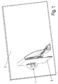
- FIG. 1 An embodiment of a front adjustment 1 for a drawer is in FIG. 1 shown.
- the front adjustment 1 is mounted between a front panel 2 and a side frame 3 in the front panel 2.
- the bearing body 25 preferably consists of a first bearing body part 4 and a second bearing body part 7.
- the bearing body 25 is fixed in the front panel 2.
- the adjusting mechanism is preferably arranged in the first bearing body part 4. With the second bearing body part 7, the front adjustment is set on the front panel 2.
- the determination is carried out in particular with two screws 8, which are inserted through holes 28 in the second bearing body part 7 and screwed into the front panel 2.
- the adjusting mechanism has a first adjusting element 5 for height adjustment of the slider and a second adjusting element 6 for lateral adjustment of the slider 9.
- Both adjusting elements 5, 6 are preferably provided on their front side with control slots 16, 21, in particular cross slots, so that an adjustment of the front adjustment can be performed in a simple manner with a screwing.
- the adjusting wheel 10 is rotatably mounted in the first bearing body part 4.
- a first inner edge portion of the adjusting wheel 10 is formed with a ring gear 12, in which a pinion 17 of the first adjusting element 5 engages.
- the adjusting wheel 10 is formed on a second inner edge portion with a protrusion 14 projecting towards the wheel center, which has a radially extending first guide slot 15, in which a guide pin 11 fastened to the slider 9 is guided.
- the adjusting mechanism further comprises an adjusting bolt 18, which is mounted linearly displaceable in the first bearing body part 4.
- This adjusting bar 18 has a second guide slot 20, in which the guide pin 11 attached to the slider and an adjustment guide 19, in which the second adjusting element 6 is guided.
- the second adjusting element 6 is in detail in the FIGS. 9a to 9c shown. It consists essentially of a head piece 22, a foot piece 24 and an eccentric between the head piece 22 and the foot piece 24 eccentrically to the center of the head piece 22 and the foot piece 24 arranged eccentric 23.
- the diameter of the eccentric 23 is slightly smaller than the width of the adjustment 19, so on the one hand, a rotation of the fixed second adjusting element 6 causes a displacement of the adjusting bar 18 perpendicular to the adjustment guide 19 and the other the eccentric 23 along the adjustment guide 19th is movable to allow simultaneous height adjustment of the slider 9.
- the adjusting bolt 18 is aligned in the first bearing body part 4 such that a just described displacement of the adjusting bolt 18 causes a lateral adjustment of the slider 9 and thus a lateral displacement of the front panel 2.
- the adjusting wheel 10 and the adjusting bolt 18 are preferably arranged one above the other in the first bearing body part 4, that the first guide slot 15 in the adjusting wheel 10 and the second guide slot 20 in the Verstellriegel 18 partially over each other, so that guided through the guide slots 15, 20 guide pin 11 is displaceable in a normal plane to the guide pin 11. As a result, a combined height and lateral adjustment of the front panel 2 is possible.
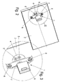
- FIG. 11a shows the front adjustment in a position in which the height adjustment is in a central position.
- the first adjusting element 5 is rotated counterclockwise, which causes just such a rotation of the adjusting wheel 10 and thereby the first guide slot 15 from a horizontal position in Figure 11a in an inclined position shown in Figure 11b, here from the left moved to the right rising position. Since the axis of rotation is arranged in this rotation in the center of the adjusting wheel 10, goes with the inclination of the guide slot 15, a displacement of the guide pin 11 upwards.
- FIG. 11c is a parking position of the front adjustment 1 shown, in which the front panel 2 is set lower.
- the first adjusting element 5 is rotated in the clockwise direction, which is accompanied by a rotation of the adjusting wheel 10 in the clockwise direction. This also results in an inclined position of the first guide slot 15, this time a falling position from left to right, which causes a displacement of the guide pin 11, in this case down.
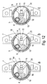
- FIGS. 12a to 12c Based on FIGS. 12a to 12c the operation of the lateral adjustment is explained by the front adjustment.
- FIG. 12a is shown a center position with respect to the side adjustment of the front adjustment.
- the guide pin 11 is positioned approximately centrally in the second guide slot 20 of the adjusting bar 18. If the second adjustment element 6 is then rotated, then the eccentric piece 23 presses against a side wall of the adjustment guide 19 and thus displaces the adjustment bolt 18 perpendicular to a longitudinal axis of the adjustment guide 19.
- the displacement of the adjustment bolt 18 causes a displacement of the guide pin arranged in the second guide slot 20 11 in the direction of displacement of the adjusting bar 18.
- the adjusting bolt 18 and the guide pin 11 in the Figures 12b to the right or in FIG. 12c shifted to the left, which corresponds to a horizontal adjustment of the diaphragm 2.
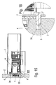
- FIGS. 15 to 22 show the front adjustment 1 according to the invention, installed in front panels 2 different material. It is in the FIGS. 15 and 16 the determination of the front adjustment 1 shown on a wood or Presspan front panel, wherein in the wood or Presspan front panel holes 30 are introduced, are screwed into the screws 8 through holes 28 in the second bearing body part 7.
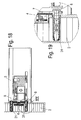
- FIG. 17 . 18 and 19 show the attachment of a front adjustment 1 on a honeycomb panel front panel 2.
- dowels 31 are embedded in the honeycomb panel front panel. This mounting variant is suitable for all lightweight panels.
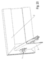
- FIGS. 20 . 21 and 22 show an attachment of the front adjustment 1 in an aluminum front panel 2.
- screws 8 are screwed into an inner wall of the aluminum front panel 2.
- This mounting variant is also suitable for Metall_, other non-ferrous metal and for plastic front panels.
Landscapes
- Drawers Of Furniture (AREA)
Description
- Die vorliegende Erfindung betrifft eine Frontverstellung für Schubkästen gemäß dem Oberbegriff des Anspruchs 1 und einen Schubkasten gemäß dem Oberbegriff des Anspruchs 14.
- Gattungsgemäße Frontverstellungen für Schubkästen sind aus dem Stand der Technik bekannt. So offenbart beispielsweise die
EP 0702915 B1 einen Beschlag zur einstellbaren Festlegung einer Frontblende, bei dem ein Beschlagmechanismus, der in einer Führungsschiene der Schubkastenaufhängung angeordnet ist, eine Höhen- und Seitenverstellung von Frontblenden ermöglicht. - Aus der
EP 0800354 B1 ist eine Halteeinrichtung für eine Frontblende einer Schublade bekannt, bei der die Arretierungsmechanik an der Schubkastenzarge angeordnet ist. - Nachteilig an diesem vorgenannten Stand der Technik ist, dass für den Verstellmechanismus einerseits ein erhöhter Bauraum in den jeweiligen Bauteilen, in denen der Verstellmechanismus eingebaut ist, insbesondere der Seitenzarge eines Schubkastens erforderlich ist. Außerdem ist bei diesen Lösungen eine Verstellung der Frontblende nicht möglich, wenn der Korpus benachbart zu einer Wand positioniert ist, d.h. zur Verstellung der Frontverstellung muß diese von der Außenseite des Schubkastens her zugänglich sein. Des Weiteren ist eine Verstellung von der Innenseite des Schubkastens her nicht möglich, wenn sich der Schubkasten in einem beladenem Zustand befindet.
- Es ist daher Aufgabe der vorliegenden Erfindung, eine Frontverstellung für Schubkästen zu schaffen, welche eine wesentlich schmalere Bauweise der Seitenzarge und eine Verstellung quer zur Auszugsrichtung des Schubkastens ermöglicht.
- Diese Aufgabe wird durch eine Frontverstellung für Schubkästen mit den Merkmalen des Anspruchs 1 sowie durch einen Schubkasten mit den Merkmalen des Anspruchs 14 gelöst.
- Erfindungsgemäß ist die Frontverstellung über einen Lagerkörper in der Frontblende festlegbar. Dadurch kann eine Verstellmöglichkeit für Frontblenden von Schubkästen geschaffen werden, mit der eine Verstellung quer zur Auszugsrichtung des Schubkastens ermöglicht ist. Dabei erfolgt der Zugriff auf die Frontverstellung in Auszugsrichtung des Schubkastens. Zudem kann dadurch, dass die Frontverstellung nicht mehr in oder an einer Schubkastenzarge angebracht ist, eine wesentlich schmalere Bauweise der Schubkastenzarge erreicht werden, wodurch ein einheitliches Schubkastendesign ermöglicht ist.
- Weitere Merkmale der Erfindung sind Gegenstand der Unteransprüche.
- Zur Höhen- und Seitenverstellung der Frontblende weist der Verstellmechanismus der Frontverstellung ein erstes Verstellelement zur Höhenverstellung und ein zweites Verstellelement zur Seitenverstellung auf. Durch diese getrennt voneinander bedienbaren Verstellelemente ist eine benutzerfreundliche Frontverstellung der Frontblende eines Schubkastens ermöglicht.
- Gemäß einer Ausgestaltung der Erfindung weist der Verstellmechanismus ein Verstellrad mit einer Innenverzahnung auf, in die eine Außenverzahnung des ersten Verstellelements eingreift. Mit einer solchen Zahnradführung ist eine exakte Verstellung ermöglicht.
- Der Lagerkörper besteht in einer bevorzugten Ausführungsform aus einem ersten und einem zweiten Lagerkörperteil, wobei das erste Lagerkörperteil bevorzugt der Unterbringung des Verstellmechanismus und das zweite Lagerkörperteil bevorzugt zur Fixierung des Lagerkörpers an der Frontblende dient.
- Bevorzugt weist der Verstellmechanismus außerdem einen Verstellriegel auf, der in dem ersten Lagerkörperteil linear verschiebbar gelagert ist und einen Verstellschlitz aufweist, in dem das zweite Verstellelement geführt ist. Dieses Verstellelement ist bevorzugt als Exzenterbolzen ausgebildet, wodurch eine gutgängige Linearverschiebung des Verstellriegels ermöglicht ist und diese zusammen mit dem Verstellrad eine exakte Höhen- und Seitenverstellung der Frontblende ermöglicht.
- Die Frontverstellung ist in Frontblenden aus allen Materialien wie z.B, Metall-, NE-Metall-, Holz-, Presspapp-, Pressspan-, Kunststoff- und Leichtbauplatten (Waben-, Sandwichplatten o.dgl.) einsetzbar.
- Die Erfindung wird nachfolgend anhand mehrerer Ausführungsbeispiele mit Bezug auf die beigefügten Zeichnungen näher erläutert, Es zeigen:
- Figur 1
- eine perspektivische Ansicht einer Frontverstellung für Schubkästen im eingebauten Zustand,
- Figur 2
- eine perspektivische Ansicht der Frontverstellung für Schubkästen im eingebauten Zustand ohne Darstellung der Seitenzarge,
- Figur 3
- eine mit III bezeichnete perspektivische Einzelheit der in
Figur 2 gezeigten Frontverstellung, - Figur 4
- eine Draufsicht auf einen Verstellmechanismus zur Höhenverstellung,
- Figuren 5a und 5b
- eine Draufsicht und eine perspektivische Ansicht des Verstellrades,
- Figuren 6a bis 6c
- verschiedene Ansichten des ersten Verstellelements,
- Figur 7
- eine Draufsicht auf einen Verstellmechanismus zur Seitenverstellung,
- Figur 8
- eine Vorderansicht des Verstellriegels,
- Figuren 9a bis 9c
- verschiedene Ansichten des ersten Verstellelements,
- Figuren 10a bis 10c
- verschiedene Ansichten des Lagerkörpers,
- Figuren 11a bis 11c
- mehrere Draufsichten der Frontverstellung in verschiedenen Positionen der Höhenverstellung,
- Figuren 12a bis 12c
- mehrere Draufsichten der Frontverstellung in verschiedenen Positionen der Seitenverstellung,
- Figuren 13a und 13b
- Seitenschnittansichten der Frontverstellung und daran angeordneter Seitenzarge in unterschiedlichen vertikalen Positionen,
- Figuren 14a und 14b
- Seitenansichten der Frontverstellung mit daran angeordneter Seitenzarge in unterschiedlichen horizontalen Positionen,
- Figuren 15
- Seitenschnittansicht der in einer Holzfrontblende angeordneten Frontverstellung,
- Figur 16
- eine mit XVI bezeichnete perspektivisch dargestellte Einzelheit der in
Figur 15 gezeigten Frontverstellung, - Figur 17
- eine perspektivische Ansicht einer Frontverstellung für Schubkästen im eingebauten Zustand in einer Wabenplatten - Frontblende,
- Figur 18
- Seitenschnittansicht der in einer Wabenplatten-Frontblende angebrachten Frontverstellung,
- Figur 19
- eine mit XIX bezeichnete perspektivisch dargestellte Einzelheit der in
Figur 18 gezeigten Frontverstellung, - Figur 20
- eine perspektivische Ansicht einer Frontverstellung für Schubkästen im eingebauten Zustand in einer AluminiumFrontblende,
- Figur 21
- Seitenschnittansicht der an einer Aluminium-Frontblende angeordneten Frontverstellung,
- Figur 22
- eine mit XXII bezeichnete perspektivisch dargestellte Einzelheit der in
Figur 21 gezeigten Frontverstellung. - Eine Ausführungsform einer Frontverstellung 1 für einen Schubkasten ist in
Figur 1 gezeigt. Die Frontverstellung 1 ist dabei zwischen einer Frontblende 2 und einer Seitenzarge 3 in der Frontblende 2 montiert. Wie in denFiguren 2 und 3 dargestellt, weist die Frontverstellung 1 ein in denFiguren 10a bis 10c näher gezeigten Lagerkörper 25, einen an dem Lagerkörper 25 angeordneten und an eine Seitenzarge 3 festlegbaren Schieber 9 und einen in dem Lagerkörper angeordneten Verstellmechanismus zur Höhen- und/oder Seitenverstellung des Schiebers 9 auf. Der Lagerkörper 25 besteht vorzugsweise aus einem ersten Lagerkörperteil 4 und einem zweiten Lagerkörperteil 7. Der Lagerkörper 25 ist dabei in der Frontblende 2 festgelegt. Dabei ist der Verstellmechanismus bevorzugt in dem ersten Lagerkörperteil 4 angeordnet. Mit dem zweiten Lagerkörperteil 7 wird die Frontverstellung an der Frontblende 2 festgelegt. Die Festlegung erfolgt dabei insbesondere mit zwei Schrauben 8, die durch Bohrungen 28 in dem zweiten Lagerkörperteil 7 durchgesteckt und in die Frontblende 2 eingeschraubt werden. - Der Verstellmechanismus weist ein erstes Verstellelement 5 zur Höhenverstellung des Schiebers und ein zweites Verstellelement 6 zur Seitenverstellung des Schiebers 9 auf. Beide Verstellelemente 5, 6 sind bevorzugt an ihrer Stirnseite mit Bedienschlitzen 16, 21, insbesondere Kreuzschlitzen, versehen, sodass eine Verstellung der Frontverstellung in einfacher Weise mit einem Schraubwerkzeug durchgeführt werden kann.
- Wie in den
Figuren 4 bis 6c gezeigt, weist der Verstellmechanismus zur Höhenverstellung des Schiebers 9 ein Verstellrad 10 auf. Das Verstellrad 10 ist in dem ersten Lagerkörperteil 4 drehbar gelagert. Ein erster Innenrandabschnitt des Verstellrades 10 ist mit einem Zahnkranz 12 ausgebildet, in die ein Ritzel 17 des ersten Verstellelements 5 eingreift. Das Verstellrad 10 ist an einem zweiten Innenrandabschnitt mit einem zur Radmitte vorstehenden Vorsprung 14 ausgebildet, welcher einen radial verlaufenden ersten Führungsschlitz 15 aufweist, in dem ein an dem Schieber 9 befestigter Führungsstift 11 geführt ist. Durch eine Drehbewegung des Verstellrades 10 kann so eine Höhenverstellung des Schiebers 9 und damit der Frontblende 2 bewirkt werden. Die genaue Darstellung der Funktionsweise wird weiter unten beschrieben. - Der Verstellmechanismus weist des Weiteren einen Verstellriegel 18 auf, der in dem ersten Lagerkörperteil 4 linear verschiebbar gelagert ist. Dieser Verstellriegel 18 weist einen zweiten Führungsschlitz 20 auf, in dem der an dem Schieber befestigte Führungsstift 11 sowie eine Verstellführung 19, in der das zweite Verstellelement 6 geführt ist.
- Das zweite Verstellelement 6 ist im Detail in den
Figuren 9a bis 9c gezeigt. Es besteht im Wesentlichen aus einem Kopfstück 22, einem Fußstück 24 und einem zwischen dem Kopfstück 22 und dem Fußstück 24 exzentrisch zum Zentrum des Kopfstücks 22 und des Fußstücks 24 angeordneten Exzenterstück 23. Der Durchmesser des Exzenterstücks 23 ist dabei geringfügig kleiner als die Breite der Verstellführung 19, sodass zum einen eine Verdrehung des fixierten zweiten Verstellelements 6 eine Verschiebung des Verstellriegels 18 senkrecht zur Verstellführung 19 bewirkt und zum anderen das Exzenterstück 23 längs der Verstellführung 19 bewegbar ist, um eine gleichzeitige Höhenverstellung des Schiebers 9 zu ermöglichen. - Der Verstellriegel 18 ist derart in dem ersten Lagerkörperteil 4 ausgerichtet, dass eine eben beschriebene Verschiebung des Verstellriegels 18 eine Seitenverstellung des Schiebers 9 und damit eine Seitenverschiebung der Frontblende 2 bewirkt.
- Das Verstellrad 10 und der Verstellriegel 18 sind vorzugsweise derart übereinander in dem ersten Lagerkörperteil 4 angeordnet, dass der erste Führungsschlitz 15 in dem Verstellrad 10 und der zweite Führungsschlitz 20 in dem Verstellriegel 18 teilweise übereinander liegen, sodass der durch die Führungsschlitze 15, 20 geführte Führungsstift 11 in einer Normalenebene zu dem Führungsstift 11 verschiebbar ist. Dadurch ist eine kombinierte Höhen- und Seitenverstellung der Frontblende 2 ermöglicht.
- Anhand der
Figuren 11a bis 11c wird nun die Funktionsweise der Höhenverstellung näher erläutert.Figur 11a zeigt dabei die Frontverstellung in einer Position, bei der die Höhenverstellung sich in einer Mittenlage befindet. Um die Frontblende 2 höher zu stellen, wird das erste Verstellelement 5 gegen den Uhrzeigersinn verdreht, was eine ebensolche Verdrehung des Verstellrades 10 bewirkt und dabei der erste Führungsschlitz 15 aus einer im Bild 11a horizontalen Stellung in eine in Figur 11b dargestellte geneigte, hier von links nach rechts ansteigende Stellung verschoben wird. Da die Drehachse bei dieser Drehung im Zentrum des Verstellrades 10 angeordnet ist, geht mit der Neigung des Führungsschlitzes 15 eine Verschiebung des Führungsstiftes 11 nach oben einher. Diese Verschiebung des Führungsstiftes 11 nach oben bewirkt, wie später noch ausführlich erläutert wird, eine Verschiebung der Frontblende 2 nach oben. InFigur 11c ist eine Stellposition der Frontverstellung 1 gezeigt, bei der die Frontblende 2 tiefer gestellt ist. Dazu wird entsprechend mit den obigen Ausführungen das erste Verstellelement 5 mit dem Uhrzeigersinn gedreht, was mit einer Verdrehung des Verstellrades 10 im Uhrzeigersinn einhergeht. Daraus resultiert ebenfalls eine geneigte Stellung des ersten Führungsschlitzes 15, diesmal eine von links nach rechts abfallende Stellung, welche eine Verschiebung des Führungsstiftes 11, in diesem Fall nach unten, bewirkt. - Anhand der
Figuren 12a bis 12c wird die Funktionsweise der Seitenverstellung durch die Frontverstellung erläutert. InFigur 12a ist eine Mittenlagenposition bezüglich der Seitenverstellung der Frontverstellung gezeigt. Dabei ist der Führungsstift 11 etwa mittig in dem zweiten Führungsschlitz 20 des Verstellriegels 18 positioniert. Verdreht man nun das zweite Verstellelement 6, so drückt das Exzenterstück 23 gegen eine Seitenwand der Verstellführung 19 und verschiebt damit den Verstellriegel 18 senkrecht zu einer Längsachse der Verstellführung 19. Mit der Verschiebung des Verstellriegels 18 geht eine Verschiebung des in dem zweiten Führungsschlitz 20 angeordneten Führungsstiftes 11 in Verschieberichtung des Verstellriegels 18 einher. Dadurch wird der Verstellriegel 18 und der Führungsstift 11 in denFiguren 12b nach rechts beziehungsweise inFigur 12c nach links verschoben, was einer horizontalen Verstellung der Fontblende 2 entspricht. - Anhand der
Figuren 13a, 13b, 14a und 14b wird nochmals die Funktionsweise einer vertikalen beziehungsweise horizontalen Verschiebung der Seitenzarge durch die erfindungsgemäße Frontverstellung aus einer anderen Perspektive verdeutlicht. Wie in denFiguren 13a und 13b gezeigt ist, erfolgt durch eine Verdrehung des ersten Verstellelements 5 eine Bewegung des Führungsstiftes 11, welcher an dem Schieber 9 befestigt ist und damit eine entsprechende Verschiebung der jeweiligen Seitenzarge 3 in eine vertikale Verschieberichtung Y. Die jeweiligen Verschiebungen der Seitenzarge sind durch durchgängige Linien der Seitenzarge in einer Ausgangsposition und gestrichelte Linien der Seitenzarge in einer Endposition dargestellt. - Entsprechend ist in den
Figuren 14a und 14b die Horizontalverschiebung der Seitenzarge gezeigt, welche durch eine Drehung des zweiten Verstellelements 6 bewirkt wird. - Die
Figuren 15 bis 22 zeigen die erfindungsgemäße Frontverstellung 1, eingebaut in Frontblenden 2 unterschiedlichen Materials. Dabei ist in denFiguren 15 und 16 die Festlegung der Frontverstellung 1 an einer Holz- oder Presspan-Frontblende gezeigt, wobei in der Holz- oder Presspan-Frontblende Bohrungen 30 eingebracht sind, in die Schrauben 8 durch Bohrungen 28 in dem zweiten Lagerkörperteil 7 eingeschraubt sind. - Die
Figur 17 ,18 und 19 zeigen die Anbringung einer Frontverstellung 1 an einer Wabenplatten-Frontblende 2. Zur Halterung der Schrauben 8 in der Wabenplatten-Frontblende 2 sind in die Wabenplatten-Frontblende 2 Dübel 31 eingelassen. Diese Befestigungsvariante ist für alle Leichtbauplatten geeignet. - Die
Figuren 20 ,21 und 22 zeigen eine Anbringung der Frontverstellung 1 in einer Aluminium-Frontblende 2. Hier sind Schrauben 8 in eine Innenwand der Aluminium-Frontblende 2 eingeschraubt. Diese Befestigungsvariante ist auch für Metall_, andere NE-Metall- und für Kunststoff-Frontblenden einsetzbar. -
- 1
- Frontverstellung
- 2
- Frontblende
- 3
- Seitenzarge
- 4
- Erstes Lagerkörperteil
- 5
- Erstes Verstellelement
- 6
- Zweites Verstellelement
- 7
- Zweites Lagerkörperteil
- 8
- Schraube
- 9
- Schieber
- 10
- Verstellrad
- 11
- Führungsstift
- 12
- Zahnkranz
- 13
- Außensteg
- 14
- Vorsprung
- 15
- Erster Führungsschlitz
- 16
- Bedienschlitz
- 17
- Ritzel
- 18
- Verstellriegel
- 19
- Verstellführung
- 20
- Zweiter Führungsschlitz
- 21
- Bedienschlitz
- 22
- Kopfstück
- 23
- Exzenterstück
- 24
- Fußstück
- 25
- Lagerkörper
- 26
- Bohrung
- 27
- Bohrung
- 28
- Bohrung
- 29
- Adapterfußhalterung
- 30
- Bohrung
- 31
- Dübel
Claims (17)
- Frontverstellung für Schubkästen, aufweisend einen Lagerkörper (25), einen an dem Lagerkörper (25) angeordneten und an einer Seitenzarge (3) festlegbaren Schieber (9), und einen in dem Lagerkörper angeordneten Verstellmechanismus zur Höhen- und/oder Seitenverstellung des Schiebers (9), dadurch gekennzeichnet, dass der Lagerkörper (25) in der Frontblende (2) festlegbar ist.
- Frontverstellung nach Anspruch 1, dadurch gekennzeichnet, dass der Verstellmechanismus ein erstes Verstellelement (5) zur Höhenverstellung des Schiebers (9) und ein zweites Verstellelement (6) zur Seitenverstellung des Schiebers (9) aufweist.
- Frontverstellung nach Anspruch 1 oder 2, dadurch gekennzeichnet, dass der Lagerkörper (25) ein erstes Lagerkörperteil (4) aufweist, in dem der Verstellmechanismus angeordnet ist und ein zweites Lagerkörperteil (7), das an der Frontblende (2) festlegbar ist.
- Frontverstellung nach Anspruch 3, dadurch gekennzeichnet, dass der Verstellmechanismus ein Verstellrad (10) aufweist, das in dem ersten Lagerkörperteil (4) drehbar gelagert ist.
- Frontverstellung nach Anspruch 4, dadurch gekennzeichnet, dass ein erster Innenrandabschnitt des Verstellrades (10) mit einem Zahnkranz (12) ausgebildet ist, in die ein Ritzel (17) des ersten Verstellelements (5) eingreift.
- Frontverstellung nach Anspruch 4 oder 5, dadurch gekennzeichnet, dass ein zweiter Innenrandabschnitt des Verstellrades (10) einen zur Radmitte vorstehenden Vorsprung (14) mit einem radial verlaufenden ersten Führungsschlitz (15) aufweist, in dem ein an dem Schieber (9) befestigter Führungsstift (11) geführt ist.
- Frontverstellung nach einem der Ansprüche 1 bis 6, dadurch gekennzeichnet, dass der Verstellmechanismus einen Verstellriegel (18) aufweist, der in dem ersten Lagerkörperteil (4) linear verschiebbar gelagert ist.
- Frontverstellung nach Anspruch 7, dadurch gekennzeichnet, dass der Verstellriegel (18) einen zweiten Führungsschlitz (20) aufweist, in dem der an dem Schieber (9) befestigte Führungsstift (11) geführt ist.
- Frontverstellung nach Anspruch 7 oder 8, dadurch gekennzeichnet, dass der Verstellriegel (18) einen Verstellschlitz (19) aufweist, in dem das zweite Verstellelement (6) geführt ist.
- Frontverstellung nach Anspruch 9, dadurch gekennzeichnet, dass das zweite Verstellelement (6) als in der Verstellführung (19) des Verstellriegels (18) angeordneter Exzenterbolzen ausgebildet ist.
- Frontverstellung nach einem der Ansprüche 7 bis 10, dadurch gekennzeichnet, dass der Verstellriegel (18) derart in dem ersten Lagerkörperteil (4) ausgerichtet ist, dass eine Verschiebung des Verstellriegels (18) eine Seitenverstellung des Schiebers bewirkt.
- Frontverstellung nach einem der Ansprüche 7 bis 11, dadurch gekennzeichnet, dass das Verstellrad (10) und der Verstellriegel (18) derart übereinander in dem ersten Lagerkörperteil (4) angeordnet sind, dass der erste Führungsschlitz (15) und der zweite Führungsschlitz (20) teilweise übereinander liegen, so dass der durch die Führungsschlitze (15, 20) geführte Führungsstift (11) in einer Normalenebene zu dem Führungsstift (11) verschiebbar ist.
- Frontverstellung nach Anspruch 12, dadurch gekennzeichnet, dass die beiden Führungsschlitze (15, 20) in einer Mittenlage der Höhenverstellung auf einer Ebene senkrecht zueinander ausgerichtet sind.
- Schubkasten mit einer Seitenzarge (3), an der eine Frontblende (2) verstellbar gehalten ist, dadurch gekennzeichnet, dass zwischen der Seitenzarge (3) und der Frontblende (2) eine Frontverstellung nach einem der vorhergehenden Ansprüche vorgesehen ist.
- Schubkasten nach Anspruch 14, dadurch gekennzeichnet, dass die Frontverstellung in der Frontblende (2) montiert ist.
- Schubkasten nach Anspruch 15, dadurch gekennzeichnet, dass die Frontblende (2) als Holz-, Presspapp- oder Presspanplatte oder als Metall-, NE-Metall- oder Kunststoff-Frontblende ausgebildet ist, in die die Frontverstellung eingelassen und über das zweite Lagerkörperteil (7) an der Frontblende (2) verschraubbar ist.
- Schubkasten nach Anspruch 15, dadurch gekennzeichnet, dass die Frontblende (2) als Leichtbauplatte ausgebildet ist, in die die Frontverstellung eingelassen ist, wobei in der Leichtbauplatte Dübel (31) eingelassen sind, mit Hilfe derer das zweite Lagerkörperteil (7) an der Frontblende (2) verschraubbar ist.
Applications Claiming Priority (2)
| Application Number | Priority Date | Filing Date | Title |
|---|---|---|---|
| DE202008014470U DE202008014470U1 (de) | 2008-10-31 | 2008-10-31 | Frontverstellung für Schubkästen |
| PCT/EP2009/064183 WO2010049436A1 (de) | 2008-10-31 | 2009-10-28 | Frontverstellung für schubkästen und schubkasten |
Publications (2)
| Publication Number | Publication Date |
|---|---|
| EP2367460A1 EP2367460A1 (de) | 2011-09-28 |
| EP2367460B1 true EP2367460B1 (de) | 2016-08-24 |
Family
ID=42035298
Family Applications (1)
| Application Number | Title | Priority Date | Filing Date |
|---|---|---|---|
| EP09744385.7A Active EP2367460B1 (de) | 2008-10-31 | 2009-10-28 | Frontverstellung für schubkästen und schubkasten |
Country Status (4)
| Country | Link |
|---|---|
| EP (1) | EP2367460B1 (de) |
| DE (1) | DE202008014470U1 (de) |
| ES (1) | ES2604966T3 (de) |
| WO (1) | WO2010049436A1 (de) |
Families Citing this family (3)
| Publication number | Priority date | Publication date | Assignee | Title |
|---|---|---|---|---|
| DE202010000086U1 (de) * | 2010-01-27 | 2011-06-01 | Paul Hettich GmbH & Co. KG, 32278 | Schubkasten mit zwei Seitenzargen und einer Frontblende |
| ITMI20130158A1 (it) * | 2013-02-05 | 2014-08-06 | Salice Arturo Spa | Dispositivo per il fissaggio regolabile di un pannello frontale di un cassetto o simile, e cassetto provvisto dei dispositivi di fissaggio stessi |
| ES2549368B1 (es) * | 2014-04-25 | 2016-08-04 | Industrias Auxiliares, S.A. | Dispositivo de ajuste para unión de partes de mueble |
Family Cites Families (10)
| Publication number | Priority date | Publication date | Assignee | Title |
|---|---|---|---|---|
| AT368608B (de) * | 1979-09-26 | 1982-10-25 | Blum Gmbh Julius | Verbindungsbeschlag fuer die befestigung einer frontplatte an einer schublade |
| AT391987B (de) * | 1987-02-04 | 1990-12-27 | Blum Gmbh Julius | Befestigungsvorrichtung fuer einstellbare frontblenden von schubladen |
| DE3930662A1 (de) * | 1989-09-14 | 1991-03-28 | Grass Ag | Frontblende mit verstelleinrichtung |
| DE4432820B4 (de) * | 1994-09-15 | 2007-03-22 | MEPLA-WERKE LAUTENSCHLäGER GMBH & CO. KG | Beschlag zur Höhenverstellung von Schubladen |
| DK0702915T3 (da) * | 1994-09-21 | 2003-03-03 | Hettich Paul Gmbh & Co | Beslag til indstillelig fastgørelse af et frontpanel |
| AT404666B (de) | 1995-10-30 | 1999-01-25 | Blum Gmbh Julius | Schublade |
| DE29902173U1 (de) * | 1999-02-08 | 2000-06-21 | Ninkaplast GmbH, 32108 Bad Salzuflen | Schubkasten mit höhen- und seitenverstellbarer Frontblende |
| DE202005001283U1 (de) * | 2005-01-27 | 2005-03-31 | Hettich Paul Gmbh & Co Kg | Schubkasten mit zwei Seitenzargen und mit einer Blende |
| DE202006005597U1 (de) * | 2006-04-04 | 2006-06-22 | Ferdinand Köhler GmbH | Frontauszug |
| DE202006014829U1 (de) * | 2006-09-25 | 2008-02-07 | Paul Hettich Gmbh & Co. Kg | Verstelleinrichtung |
-
2008
- 2008-10-31 DE DE202008014470U patent/DE202008014470U1/de not_active Expired - Lifetime
-
2009
- 2009-10-28 WO PCT/EP2009/064183 patent/WO2010049436A1/de not_active Ceased
- 2009-10-28 ES ES09744385.7T patent/ES2604966T3/es active Active
- 2009-10-28 EP EP09744385.7A patent/EP2367460B1/de active Active
Also Published As
| Publication number | Publication date |
|---|---|
| WO2010049436A1 (de) | 2010-05-06 |
| DE202008014470U1 (de) | 2010-03-18 |
| ES2604966T3 (es) | 2017-03-10 |
| EP2367460A1 (de) | 2011-09-28 |
Similar Documents
| Publication | Publication Date | Title |
|---|---|---|
| EP3603449B1 (de) | Ausziehführung für eine schublade | |
| EP2873792B1 (de) | Türband | |
| DE102005052123B3 (de) | Lenksäule für ein Kraftfahrzeug | |
| EP1256290B1 (de) | Ausziehführung für eine Schublade | |
| EP2158372B1 (de) | Tür- oder fensterscharnier | |
| EP3681347B1 (de) | Blendenträger und schubkasten | |
| AT395282B (de) | Fuehrungsschienengarnitur fuer schubladen od.dgl. | |
| DE3930662A1 (de) | Frontblende mit verstelleinrichtung | |
| AT401012B (de) | Einrichtung zum festlegen von rollen an einspurigen rollschuhen | |
| EP2367460A1 (de) | Frontverstellung für schubkästen und schubkasten | |
| EP2353440A1 (de) | Beschlag für einen Eckschrank und Eckschrank | |
| AT402528B (de) | Seitenverstellbares ladenband | |
| DD298137A5 (de) | Strickmaschine | |
| WO2019057591A1 (de) | Führungsbeschlag für ein schiebetürmöbel und schiebetürmöbel | |
| EP1223275B1 (de) | Band für Türen oder Fenster | |
| DE20004106U1 (de) | Drehband für Fenster oder Türen | |
| AT526953B1 (de) | Führungsanordnung zur Führung eines bewegbaren Möbelteils | |
| DE19526016A1 (de) | Exzenterverstelleinrichtung für einen Beschlag für Fenster, Türen oder dergleichen | |
| DE2722729A1 (de) | Zeichentisch | |
| DE8209457U1 (de) | Tuerdruecker-garnitur mit holzdrueckern | |
| EP4162838A1 (de) | Schubladenausziehführung | |
| EP2085533A2 (de) | Verbindungsvorrichtung zur Verbindung von Stufe und Wange einer Treppe | |
| DE19541235A1 (de) | Fräslehre für Türen | |
| EP1688570A1 (de) | Band für Türen, Fenster oder dergleichen | |
| DE7509926U (de) | Gleitfuehrung fuer eine in einem moebelstueck o.dgl. angeordnete schublade |
Legal Events
| Date | Code | Title | Description |
|---|---|---|---|
| PUAI | Public reference made under article 153(3) epc to a published international application that has entered the european phase |
Free format text: ORIGINAL CODE: 0009012 |
|
| 17P | Request for examination filed |
Effective date: 20110527 |
|
| AK | Designated contracting states |
Kind code of ref document: A1 Designated state(s): AT BE BG CH CY CZ DE DK EE ES FI FR GB GR HR HU IE IS IT LI LT LU LV MC MK MT NL NO PL PT RO SE SI SK SM TR |
|
| DAX | Request for extension of the european patent (deleted) | ||
| GRAP | Despatch of communication of intention to grant a patent |
Free format text: ORIGINAL CODE: EPIDOSNIGR1 |
|
| INTG | Intention to grant announced |
Effective date: 20160309 |
|
| GRAP | Despatch of communication of intention to grant a patent |
Free format text: ORIGINAL CODE: EPIDOSNIGR1 |
|
| INTG | Intention to grant announced |
Effective date: 20160513 |
|
| GRAS | Grant fee paid |
Free format text: ORIGINAL CODE: EPIDOSNIGR3 |
|
| GRAA | (expected) grant |
Free format text: ORIGINAL CODE: 0009210 |
|
| AK | Designated contracting states |
Kind code of ref document: B1 Designated state(s): AT BE BG CH CY CZ DE DK EE ES FI FR GB GR HR HU IE IS IT LI LT LU LV MC MK MT NL NO PL PT RO SE SI SK SM TR |
|
| REG | Reference to a national code |
Ref country code: GB Ref legal event code: FG4D Free format text: NOT ENGLISH |
|
| REG | Reference to a national code |
Ref country code: CH Ref legal event code: EP |
|
| REG | Reference to a national code |
Ref country code: AT Ref legal event code: REF Ref document number: 822249 Country of ref document: AT Kind code of ref document: T Effective date: 20160915 |
|
| REG | Reference to a national code |
Ref country code: IE Ref legal event code: FG4D Free format text: LANGUAGE OF EP DOCUMENT: GERMAN |
|
| REG | Reference to a national code |
Ref country code: DE Ref legal event code: R096 Ref document number: 502009012997 Country of ref document: DE |
|
| REG | Reference to a national code |
Ref country code: LT Ref legal event code: MG4D |
|
| REG | Reference to a national code |
Ref country code: NL Ref legal event code: MP Effective date: 20160824 |
|
| PG25 | Lapsed in a contracting state [announced via postgrant information from national office to epo] |
Ref country code: HR Free format text: LAPSE BECAUSE OF FAILURE TO SUBMIT A TRANSLATION OF THE DESCRIPTION OR TO PAY THE FEE WITHIN THE PRESCRIBED TIME-LIMIT Effective date: 20160824 Ref country code: NO Free format text: LAPSE BECAUSE OF FAILURE TO SUBMIT A TRANSLATION OF THE DESCRIPTION OR TO PAY THE FEE WITHIN THE PRESCRIBED TIME-LIMIT Effective date: 20161124 Ref country code: FI Free format text: LAPSE BECAUSE OF FAILURE TO SUBMIT A TRANSLATION OF THE DESCRIPTION OR TO PAY THE FEE WITHIN THE PRESCRIBED TIME-LIMIT Effective date: 20160824 Ref country code: LT Free format text: LAPSE BECAUSE OF FAILURE TO SUBMIT A TRANSLATION OF THE DESCRIPTION OR TO PAY THE FEE WITHIN THE PRESCRIBED TIME-LIMIT Effective date: 20160824 Ref country code: NL Free format text: LAPSE BECAUSE OF FAILURE TO SUBMIT A TRANSLATION OF THE DESCRIPTION OR TO PAY THE FEE WITHIN THE PRESCRIBED TIME-LIMIT Effective date: 20160824 |
|
| PG25 | Lapsed in a contracting state [announced via postgrant information from national office to epo] |
Ref country code: SE Free format text: LAPSE BECAUSE OF FAILURE TO SUBMIT A TRANSLATION OF THE DESCRIPTION OR TO PAY THE FEE WITHIN THE PRESCRIBED TIME-LIMIT Effective date: 20160824 Ref country code: GR Free format text: LAPSE BECAUSE OF FAILURE TO SUBMIT A TRANSLATION OF THE DESCRIPTION OR TO PAY THE FEE WITHIN THE PRESCRIBED TIME-LIMIT Effective date: 20161125 Ref country code: LV Free format text: LAPSE BECAUSE OF FAILURE TO SUBMIT A TRANSLATION OF THE DESCRIPTION OR TO PAY THE FEE WITHIN THE PRESCRIBED TIME-LIMIT Effective date: 20160824 Ref country code: PT Free format text: LAPSE BECAUSE OF FAILURE TO SUBMIT A TRANSLATION OF THE DESCRIPTION OR TO PAY THE FEE WITHIN THE PRESCRIBED TIME-LIMIT Effective date: 20161226 Ref country code: BE Free format text: LAPSE BECAUSE OF NON-PAYMENT OF DUE FEES Effective date: 20161031 |
|
| REG | Reference to a national code |
Ref country code: ES Ref legal event code: FG2A Ref document number: 2604966 Country of ref document: ES Kind code of ref document: T3 Effective date: 20170310 |
|
| PG25 | Lapsed in a contracting state [announced via postgrant information from national office to epo] |
Ref country code: EE Free format text: LAPSE BECAUSE OF FAILURE TO SUBMIT A TRANSLATION OF THE DESCRIPTION OR TO PAY THE FEE WITHIN THE PRESCRIBED TIME-LIMIT Effective date: 20160824 Ref country code: RO Free format text: LAPSE BECAUSE OF FAILURE TO SUBMIT A TRANSLATION OF THE DESCRIPTION OR TO PAY THE FEE WITHIN THE PRESCRIBED TIME-LIMIT Effective date: 20160824 |
|
| REG | Reference to a national code |
Ref country code: DE Ref legal event code: R097 Ref document number: 502009012997 Country of ref document: DE |
|
| PG25 | Lapsed in a contracting state [announced via postgrant information from national office to epo] |
Ref country code: SM Free format text: LAPSE BECAUSE OF FAILURE TO SUBMIT A TRANSLATION OF THE DESCRIPTION OR TO PAY THE FEE WITHIN THE PRESCRIBED TIME-LIMIT Effective date: 20160824 Ref country code: PL Free format text: LAPSE BECAUSE OF FAILURE TO SUBMIT A TRANSLATION OF THE DESCRIPTION OR TO PAY THE FEE WITHIN THE PRESCRIBED TIME-LIMIT Effective date: 20160824 Ref country code: SK Free format text: LAPSE BECAUSE OF FAILURE TO SUBMIT A TRANSLATION OF THE DESCRIPTION OR TO PAY THE FEE WITHIN THE PRESCRIBED TIME-LIMIT Effective date: 20160824 Ref country code: DK Free format text: LAPSE BECAUSE OF FAILURE TO SUBMIT A TRANSLATION OF THE DESCRIPTION OR TO PAY THE FEE WITHIN THE PRESCRIBED TIME-LIMIT Effective date: 20160824 Ref country code: BG Free format text: LAPSE BECAUSE OF FAILURE TO SUBMIT A TRANSLATION OF THE DESCRIPTION OR TO PAY THE FEE WITHIN THE PRESCRIBED TIME-LIMIT Effective date: 20161124 Ref country code: CZ Free format text: LAPSE BECAUSE OF FAILURE TO SUBMIT A TRANSLATION OF THE DESCRIPTION OR TO PAY THE FEE WITHIN THE PRESCRIBED TIME-LIMIT Effective date: 20160824 |
|
| REG | Reference to a national code |
Ref country code: CH Ref legal event code: PL |
|
| PLBE | No opposition filed within time limit |
Free format text: ORIGINAL CODE: 0009261 |
|
| STAA | Information on the status of an ep patent application or granted ep patent |
Free format text: STATUS: NO OPPOSITION FILED WITHIN TIME LIMIT |
|
| GBPC | Gb: european patent ceased through non-payment of renewal fee |
Effective date: 20161124 |
|
| REG | Reference to a national code |
Ref country code: IE Ref legal event code: MM4A |
|
| REG | Reference to a national code |
Ref country code: FR Ref legal event code: ST Effective date: 20170630 |
|
| PG25 | Lapsed in a contracting state [announced via postgrant information from national office to epo] |
Ref country code: CH Free format text: LAPSE BECAUSE OF NON-PAYMENT OF DUE FEES Effective date: 20161031 Ref country code: FR Free format text: LAPSE BECAUSE OF NON-PAYMENT OF DUE FEES Effective date: 20161102 Ref country code: LI Free format text: LAPSE BECAUSE OF NON-PAYMENT OF DUE FEES Effective date: 20161031 |
|
| 26N | No opposition filed |
Effective date: 20170526 |
|
| PG25 | Lapsed in a contracting state [announced via postgrant information from national office to epo] |
Ref country code: SI Free format text: LAPSE BECAUSE OF FAILURE TO SUBMIT A TRANSLATION OF THE DESCRIPTION OR TO PAY THE FEE WITHIN THE PRESCRIBED TIME-LIMIT Effective date: 20160824 Ref country code: LU Free format text: LAPSE BECAUSE OF NON-PAYMENT OF DUE FEES Effective date: 20161028 |
|
| PG25 | Lapsed in a contracting state [announced via postgrant information from national office to epo] |
Ref country code: GB Free format text: LAPSE BECAUSE OF NON-PAYMENT OF DUE FEES Effective date: 20161124 Ref country code: IE Free format text: LAPSE BECAUSE OF NON-PAYMENT OF DUE FEES Effective date: 20161028 |
|
| REG | Reference to a national code |
Ref country code: BE Ref legal event code: MM Effective date: 20161031 |
|
| PG25 | Lapsed in a contracting state [announced via postgrant information from national office to epo] |
Ref country code: HU Free format text: LAPSE BECAUSE OF FAILURE TO SUBMIT A TRANSLATION OF THE DESCRIPTION OR TO PAY THE FEE WITHIN THE PRESCRIBED TIME-LIMIT; INVALID AB INITIO Effective date: 20091028 Ref country code: CY Free format text: LAPSE BECAUSE OF FAILURE TO SUBMIT A TRANSLATION OF THE DESCRIPTION OR TO PAY THE FEE WITHIN THE PRESCRIBED TIME-LIMIT Effective date: 20160824 |
|
| PG25 | Lapsed in a contracting state [announced via postgrant information from national office to epo] |
Ref country code: MT Free format text: LAPSE BECAUSE OF FAILURE TO SUBMIT A TRANSLATION OF THE DESCRIPTION OR TO PAY THE FEE WITHIN THE PRESCRIBED TIME-LIMIT Effective date: 20160824 Ref country code: MK Free format text: LAPSE BECAUSE OF FAILURE TO SUBMIT A TRANSLATION OF THE DESCRIPTION OR TO PAY THE FEE WITHIN THE PRESCRIBED TIME-LIMIT Effective date: 20160824 Ref country code: IS Free format text: LAPSE BECAUSE OF FAILURE TO SUBMIT A TRANSLATION OF THE DESCRIPTION OR TO PAY THE FEE WITHIN THE PRESCRIBED TIME-LIMIT Effective date: 20160824 Ref country code: MC Free format text: LAPSE BECAUSE OF FAILURE TO SUBMIT A TRANSLATION OF THE DESCRIPTION OR TO PAY THE FEE WITHIN THE PRESCRIBED TIME-LIMIT Effective date: 20160824 |
|
| PGFP | Annual fee paid to national office [announced via postgrant information from national office to epo] |
Ref country code: TR Payment date: 20201023 Year of fee payment: 12 |
|
| PGFP | Annual fee paid to national office [announced via postgrant information from national office to epo] |
Ref country code: ES Payment date: 20201117 Year of fee payment: 12 Ref country code: IT Payment date: 20201030 Year of fee payment: 12 Ref country code: AT Payment date: 20201016 Year of fee payment: 12 |
|
| REG | Reference to a national code |
Ref country code: AT Ref legal event code: MM01 Ref document number: 822249 Country of ref document: AT Kind code of ref document: T Effective date: 20211028 |
|
| PG25 | Lapsed in a contracting state [announced via postgrant information from national office to epo] |
Ref country code: AT Free format text: LAPSE BECAUSE OF NON-PAYMENT OF DUE FEES Effective date: 20211028 |
|
| PG25 | Lapsed in a contracting state [announced via postgrant information from national office to epo] |
Ref country code: IT Free format text: LAPSE BECAUSE OF NON-PAYMENT OF DUE FEES Effective date: 20211028 |
|
| REG | Reference to a national code |
Ref country code: DE Ref legal event code: R084 Ref document number: 502009012997 Country of ref document: DE |
|
| REG | Reference to a national code |
Ref country code: ES Ref legal event code: FD2A Effective date: 20230221 |
|
| PG25 | Lapsed in a contracting state [announced via postgrant information from national office to epo] |
Ref country code: ES Free format text: LAPSE BECAUSE OF NON-PAYMENT OF DUE FEES Effective date: 20211029 |
|
| P01 | Opt-out of the competence of the unified patent court (upc) registered |
Effective date: 20230415 |
|
| PGFP | Annual fee paid to national office [announced via postgrant information from national office to epo] |
Ref country code: DE Payment date: 20251020 Year of fee payment: 17 |