EP2158372B1 - Tür- oder fensterscharnier - Google Patents
Tür- oder fensterscharnier Download PDFInfo
- Publication number
- EP2158372B1 EP2158372B1 EP08760035A EP08760035A EP2158372B1 EP 2158372 B1 EP2158372 B1 EP 2158372B1 EP 08760035 A EP08760035 A EP 08760035A EP 08760035 A EP08760035 A EP 08760035A EP 2158372 B1 EP2158372 B1 EP 2158372B1
- Authority
- EP
- European Patent Office
- Prior art keywords
- plate
- door
- hinge
- window
- intermediate member
- Prior art date
- Legal status (The legal status is an assumption and is not a legal conclusion. Google has not performed a legal analysis and makes no representation as to the accuracy of the status listed.)
- Not-in-force
Links
Images


Classifications
-
- E—FIXED CONSTRUCTIONS
- E05—LOCKS; KEYS; WINDOW OR DOOR FITTINGS; SAFES
- E05D—HINGES OR SUSPENSION DEVICES FOR DOORS, WINDOWS OR WINGS
- E05D7/00—Hinges or pivots of special construction
- E05D7/02—Hinges or pivots of special construction for use on the right-hand as well as the left-hand side; Convertible right-hand or left-hand hinges
-
- E—FIXED CONSTRUCTIONS
- E05—LOCKS; KEYS; WINDOW OR DOOR FITTINGS; SAFES
- E05D—HINGES OR SUSPENSION DEVICES FOR DOORS, WINDOWS OR WINGS
- E05D5/00—Construction of single parts, e.g. the parts for attachment
- E05D5/02—Parts for attachment, e.g. flaps
- E05D5/0215—Parts for attachment, e.g. flaps for attachment to profile members or the like
- E05D5/0223—Parts for attachment, e.g. flaps for attachment to profile members or the like with parts, e.g. screws, extending through the profile wall or engaging profile grooves
- E05D5/023—Parts for attachment, e.g. flaps for attachment to profile members or the like with parts, e.g. screws, extending through the profile wall or engaging profile grooves with parts extending through the profile wall
-
- E—FIXED CONSTRUCTIONS
- E05—LOCKS; KEYS; WINDOW OR DOOR FITTINGS; SAFES
- E05D—HINGES OR SUSPENSION DEVICES FOR DOORS, WINDOWS OR WINGS
- E05D7/00—Hinges or pivots of special construction
- E05D7/0009—Adjustable hinges
- E05D7/0018—Adjustable hinges at the hinge axis
- E05D7/0027—Adjustable hinges at the hinge axis in an axial direction
-
- E—FIXED CONSTRUCTIONS
- E05—LOCKS; KEYS; WINDOW OR DOOR FITTINGS; SAFES
- E05D—HINGES OR SUSPENSION DEVICES FOR DOORS, WINDOWS OR WINGS
- E05D7/00—Hinges or pivots of special construction
- E05D7/04—Hinges adjustable relative to the wing or the frame
- E05D7/0415—Hinges adjustable relative to the wing or the frame with adjusting drive means
- E05D7/0423—Screw-and-nut mechanisms
-
- E—FIXED CONSTRUCTIONS
- E05—LOCKS; KEYS; WINDOW OR DOOR FITTINGS; SAFES
- E05D—HINGES OR SUSPENSION DEVICES FOR DOORS, WINDOWS OR WINGS
- E05D7/00—Hinges or pivots of special construction
- E05D7/04—Hinges adjustable relative to the wing or the frame
- E05D2007/0492—Hinges adjustable relative to the wing or the frame in three directions
-
- E—FIXED CONSTRUCTIONS
- E05—LOCKS; KEYS; WINDOW OR DOOR FITTINGS; SAFES
- E05Y—INDEXING SCHEME ASSOCIATED WITH SUBCLASSES E05D AND E05F, RELATING TO CONSTRUCTION ELEMENTS, ELECTRIC CONTROL, POWER SUPPLY, POWER SIGNAL OR TRANSMISSION, USER INTERFACES, MOUNTING OR COUPLING, DETAILS, ACCESSORIES, AUXILIARY OPERATIONS NOT OTHERWISE PROVIDED FOR, APPLICATION THEREOF
- E05Y2600/00—Mounting or coupling arrangements for elements provided for in this subclass
- E05Y2600/60—Mounting or coupling members; Accessories therefor
- E05Y2600/622—Dowels; Pins
-
- E—FIXED CONSTRUCTIONS
- E05—LOCKS; KEYS; WINDOW OR DOOR FITTINGS; SAFES
- E05Y—INDEXING SCHEME ASSOCIATED WITH SUBCLASSES E05D AND E05F, RELATING TO CONSTRUCTION ELEMENTS, ELECTRIC CONTROL, POWER SUPPLY, POWER SIGNAL OR TRANSMISSION, USER INTERFACES, MOUNTING OR COUPLING, DETAILS, ACCESSORIES, AUXILIARY OPERATIONS NOT OTHERWISE PROVIDED FOR, APPLICATION THEREOF
- E05Y2900/00—Application of doors, windows, wings or fittings thereof
- E05Y2900/10—Application of doors, windows, wings or fittings thereof for buildings or parts thereof
- E05Y2900/13—Type of wing
- E05Y2900/132—Doors
-
- E—FIXED CONSTRUCTIONS
- E05—LOCKS; KEYS; WINDOW OR DOOR FITTINGS; SAFES
- E05Y—INDEXING SCHEME ASSOCIATED WITH SUBCLASSES E05D AND E05F, RELATING TO CONSTRUCTION ELEMENTS, ELECTRIC CONTROL, POWER SUPPLY, POWER SIGNAL OR TRANSMISSION, USER INTERFACES, MOUNTING OR COUPLING, DETAILS, ACCESSORIES, AUXILIARY OPERATIONS NOT OTHERWISE PROVIDED FOR, APPLICATION THEREOF
- E05Y2900/00—Application of doors, windows, wings or fittings thereof
- E05Y2900/10—Application of doors, windows, wings or fittings thereof for buildings or parts thereof
- E05Y2900/13—Type of wing
- E05Y2900/148—Windows
Definitions
- the invention relates to a door or window hinge with two hinge parts rotatably connected to one another about a common hinge axis, wherein at least the door or window-side hinge part has a plate-like portion, which with a holding piece insertable into a groove on the front side of the door or the window cooperates firmly and detachably connectable, wherein the plate-like portion is aligned in a direction parallel to the hinge axis imaginary plane, and wherein the plate-like portion is adjustable in a perpendicular to the plane of the plate-like portion imaginary plane relative to the holding piece.
- the GB 2 346 173 A shows a door or window hinge of the type mentioned, in which the plate-like portion and the holding piece each have a kind of flat teeth, which prevent each movement between the holding piece and the plate-like portion in mutual engagement.
- the adjustment is limited because it is limited to a direction in the plane of the teeth.
- a door or window hinge provided with two about a common hinge axis rotatable together operatively connected hinge parts, wherein at least the door or window-side hinge part has a plate-like portion which cooperates firmly and detachably connectable with a usable in a groove on the front side of the door or the window holding piece.
- the plate-like portion is aligned in a parallel and perpendicular to the hinge axis imaginary plane and in a plane perpendicular to the plane of the plate-like portion imaginary plane relative to the holding piece adjustable. Nevertheless, however, only a limited adjustability of the door or window hinge is given.
- the invention has for its object to provide a door or window hinge of the type mentioned, which can be mounted without special preparation and milling on the door or window and also provides virtually all adjustment options.
- the hinge part with the plate-like portion can therefore be designed in a very simple construction.
- the intermediate piece is held vertically adjustable in the holding piece and on the other hand supported on the underside of the plate-like portion.
- the mounting height thus results from the position of the intermediate piece, which protrudes more or less far over the holding piece or is sunk in this.
- a simple structural measure provides that the intermediate piece by means of an engaging in the holding piece and / or in a threaded sleeve formed on the underside adjusting screw height adjustable is held. It is therefore possible in an exact and relatively large range, an adjustment in this direction. Nevertheless, it is ensured a relatively long thread engagement for the adjusting screw.
- An advantageous embodiment is further that the adjusting screws are accessible through corresponding openings in the plate-like portion without disassembly of the plate-like portion. Therefore, it is only the screws for the connection between the plate-like portion and the intermediate piece to solve something, after which the adjusting screws can be operated. Then tighten the screws for the connection again.
- a door hinge 1 with two about a common hinge axis 2 rotatable together operatively connected hinge parts 3 and 4 will be explained.
- profiles 5 and 6 are designed for the door and for the door frame as plastic hollow sections.
- the invention can also be used in metal profiles or in wood profiles or profiles of material combinations.
- a hinge according to the invention can also be used in the same way in the case of windows or in the case of large gates and possibly also in furniture construction.
- the door or window-side hinge part 3 on a plate-like portion 8 which cooperates with a insertable into the groove 7 on the front side of the door holding piece 9 fixed and releasably connectable.
- the plate-like portion 8 is aligned in a direction parallel to the hinge axis 2 imaginary plane and in a plane perpendicular to the plane of the plate-like portion 8 imaginary plane relative to the retaining piece 9 adjustable.
- the door or window-side hinge part 3 associated holding piece 8 and the second hinge part 4 have protruding mounting pins 10 and 11 or -stege, which engage in holes on the door or on the door frame and by means of additional, at a distance parallel to the mounting pins 10 and 11 or -stegen aligned screws can be fixed.
- retaining piece 9 is for the most part sunk into the formed on the front side of the door, provided according to standards groove 7 and by means of at least on the two longitudinal sides of the retaining piece 9 trained edge portion 12 is supported on a formed in the region of the Nutab gleiches web 13.
- the plate-like portion 8 of the hinge part 3 can be fixed by means of screws 15 to an intermediate piece 14 inserted into the retaining piece 9, corresponding threaded sleeves 20 being formed on the intermediate piece 14.
- the intermediate piece 14 is held vertically adjustable on the one hand in the holding piece 9 and on the other hand supported on the underside of the plate-like portion 8.
- the intermediate piece 14 is advantageously held vertically adjustable by means of an adjusting screw 17 engaging in the holding piece 9 and / or in a threaded sleeve 16 formed on the underside of the same.
- the head 18 of the adjusting screw 17 is made very flat so that it does not have too much space between the spacer 14 and the plate-like portion. Due to the adjoining the retaining piece 9 threaded sleeve 16 and a relatively long threaded engagement between the adjusting screw 17 and the retaining piece 9 and the threaded sleeve 16 is present.
- the screws 15 for connecting the plate-like portion 8 and the intermediate piece 14 engage through longitudinal slots 19 in the section 8 a.
- the longitudinal slots 19 are at right angles to the hinge axis 2 imaginary planes. As a result, a corresponding adjustment is given in the extent of the length of these longitudinal slots.
- Threaded grooves 25 are provided on one of the bore halves 23 and 24 of the plate-like portion 8 and the intermediate piece 14, wherein in the opposite bore half 23 at one end a termination or stop wall 26 is provided for the associated end of the adjusting screw 22.
- the plate-like portion 8 is displaced in the direction of the longitudinal slots 19 or the plate-like portion 8 can be moved in the other direction to the stop wall 26. After tightening the screws 15 in turn the new setting is determined.
- a hinge axis 2 between the two hinge parts 3 and 4 forming bolt can be made to achieve a height adjustment of the mounted hinge 1 adjustable, in which case a number of known possibilities can be used. It can thus be a relative height adjustment between the two hinge parts 3 and 4.
Landscapes
- Engineering & Computer Science (AREA)
- Mechanical Engineering (AREA)
- Hinges (AREA)
- Window Of Vehicle (AREA)
Description
- Die Erfindung betrifft ein Tür- oder Fensterscharnier mit zwei um eine gemeinsame Scharnierachse verdrehbar miteinander in Wirkverbindung stehenden Scharnierteilen, wobei wenigstens das tür- oder fensterseitige Scharnierteil einen plattenartigen Abschnitt aufweist, welcher mit einem in eine Nut an der Stirnseite der Tür oder des Fensters einsetzbaren Haltestück fest und lösbar verbindbar zusammenwirkt, wobei der plattenartige Abschnitt in einer parallel zur Scharnierachse gedachten Ebene ausgerichtet ist, und wobei der plattenartige Abschnitt in einer rechtwinklig zur Ebene des plattenartigen Abschnittes gedachten Ebene gegenüber dem Haltestück verstellbar ist.
- Tür- oder Feristerscharniere sind insbesondere dann, wenn eine Mehrfacheinstellmöglichkeit gegeben sein soll, in der Regel kompliziert im Aufbau und daher aufwendig in der Fertigung und außerdem schlecht bedienbar. Ferner muss in der Regel eine besondere Öffnung in der Tür oder im Fenster oder aber im Tür-oder Fensterrahmen hergestellt werden, bevor die Montage erfolgen kann.
- Die
GB 2 346 173 A - Bei einer anderen bekannten Ausgestaltung (
DE19842769A1 ) ist ein Tür- oder Fensterscharnier mit zwei um eine gemeinsame Scharnierachse verdrehbar miteinander in Wirkverbindung stehenden Scharnierteilen vorgesehen, wobei wenigstens das tür- oder fensterseitige Scharnierteil einen plattenartigen Abschnitt aufweist, welcher mit einem in eine Nut an der Stirnseite der Tür oder des Fensters einsetzbaren Haltestück fest und lösbar verbindbar zusammenwirkt. Der plattenartige Abschnitt ist in einer parallel und rechtwinklig zur Scharnierachse gedachten Ebene ausgerichtet und in einer rechtwinklig zur Ebene des plattenartigen Abschnittes gedachten Ebene gegenüber dem Haltestück verstellbar. Trotzdem ist aber eine nur beschränkte Verstellbarkeit des Tür- oder Fensterscharniers gegeben. - Die Erfindung hat sich zur Aufgabe gestellt, ein Tür- oder Fensterscharnier der eingangs genannten Art zu schaffen, welches ohne besondere Vorarbeiten und Fräsarbeiten an der Tür oder dem Fenster montiert werden kann und zudem praktisch alle Verstellmöglichkeiten vorsieht.
- Erfindungsgemäß gelingt dies dadurch, dass der plattenartige Abschnitt des einen Scharnierteiles an einem in das Haltestück eingesetzten Zwischenstück mittels Schrauben festlegbar ist.
- Auf diese Weise ist es möglich, dass die Verstellmöglichkeiten im Wesentlichen dem Haltestück mit dem Zwischenstück zuzuordnen sind. Das Scharnierteil mit dem plattenartigen Abschnitt kann also in einer sehr einfachen Konstruktion gestaltet werden.
- In diesem Zusammenhang ist es vorteilhaft, dass das Zwischenstück im Haltestück höhenverstellbar gehalten ist und andererseits an der Unterseite des plattenartigen Abschnittes abgestützt ist. Die Montagehöhe ergibt sich also aus der Lage des Zwischenstückes, welches ja mehr oder weniger weit über das Haltestück vorsteht oder in diesem versenkt ist.
- Eine einfache konstruktive Maßnahme sieht dabei vor, dass das Zwischenstück mittels einer in das Haltestück und/oder in eine an der Unterseite desselben ausgebildete Gewindehülse eingreifenden Verstellschraube höhenverstellbar gehalten ist. Es ist daher in einem exakten und relativ großen Bereich eine Verstellung in diese Richtung möglich. Trotzdem ist für einen relativ langen Gewindeeingriff für die Verstellschraube gesorgt.
- Damit auch eine Verstellung in der Ebene des plattenartigen Abschnittes und insbesondere in Richtung quer zur Scharnierachse in einfacher Weise möglich ist, wird vorgeschlagen, dass die Schrauben zur Verbindung des plattenartigen Abschnittes und des Zwischenstückes durch Längsschlitze in dem Abschnitt eingreifen, welche in rechtwinklig zur Scharnierachse gedachten Ebenen liegen. Für einen Verstellvorgang sowohl der Höhenlage des plattenartigen Abschnittes als auch für dessen seitliche Verstellung sind lediglich die Schrauben etwas zu lösen und nach den Einstellarbeiten wieder anzuziehen.
- In diesem Zusammenhang ist eine konstruktiv optimale Lösung darin zu sehen, dass zwischen dem plattenartigen Abschnitt und dem Zwischenstück in Verstellrichtung des Scharnierteiles gesehen eine von dem plattenartigen Abschnitt und von dem Zwischenstück gemeinsam gebildete Bohrung vorgesehen ist, in welche eine weitere Verstellschraube eingreift. Nach dem Einlegen dieser Verstellschraube zwischen das Zwischenstück und den plattenartigen Abschnitt und nach dem Verschrauben dieser Teile wird diese Verstellschraube unverlierbar gehalten.
- Damit eine einfache Verstellbewegung ausgeführt werden kann, wird vorgeschlagen, dass an einer der Bohrungshälften des plattenartigen Abschnittes und des Zwischenstückes gewindeartige Nuten vorgesehen sind, wobei in der gegenüberliegenden Bohrungshälfte an einem Ende eine Abschluss- oder Anschlagwand für das zugeordnete Ende der weiteren Verstellschraube vorgesehen ist. Es wird damit beim Verdrehen dieser Verstellschraube eine Relativbewegung in Achsrichtung der Verstellschraube hervorgerufen, wobei aber das eine Ende der weiteren Verstellschraube an einer Abschluss- oder Anschlagwand ansteht und somit eine Verschiebebewegung des plattenartigen Abschnittes bewirkt wird. Diese Verschiebebewegung ist natürlich nur möglich, wenn die den plattenartigen Abschnitt und das Zwischenstück verbindenden Schrauben gelöst sind.
- Eine vorteilhafte Ausgestaltung liegt ferner darin, dass die Verstellschrauben durch entsprechende Öffnungen in dem plattenartigen Abschnitt ohne Demontage des plattenartigen Abschnittes zugänglich sind. Es sind daher nur die Schrauben für die Verbindung zwischen dem plattenartigen Abschnitt und dem Zwischenstück etwas zu lösen, worauf die Verstellschrauben betätigt werden können. Anschließend sind dann wieder die Schrauben für die Verbindung anzuziehen.
- Ferner wird vorgeschlagen, dass im Bereich der Enden oder mit geringem Abstand von den Enden des Haltestückes Führungsstege als Anschläge für zwei einander gegenüber liegende und parallel zu den Längsschlitzen verlaufende Seitenbegrenzungen des plattenartigen Abschnittes ausgebildet sind. Es ergibt sich dadurch eine sichere Halterung der plattenartigen Abschnitte in vertikaler Richtung.
- Ausführungsbeispiele der Erfindung werden in der nachstehenden Beschreibung anhand der Zeichnungen noch näher erläutert. Es zeigen:
- Fig.1
- eine Schrägansicht eines Teiles eines Türprofils und eines Türrahmenprofils mit eingesetztem Scharnier;
- Fig.2
- einen Horizontalschnitt durch ein Türprofil und ein Türrahmenprofil mit eingesetztem Scharnier;
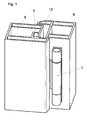
- Fig.3
- eine Schrägansicht dieses Scharniers;
- Fig. 4
- eine Explosionszeichnung des Scharniers, wobei die Teile von unten gesehen dargestellt sind;
- Fig. 5
- eine Explosionszeichnung des Scharniers, wobei die Teile von oben gesehen dargestellt sind.
- Anhand der
Fig. 1 und2 wird die Anordnung eines Türscharniers 1 mit zwei um eine gemeinsame Scharnierachse 2 verdrehbar miteinander in Wirkverbindung stehenden Scharnierteilen 3 und 4 erläutert. In diesen beiden Darstellungen sind Profile 5 und 6 für die Tür und für den Türrahmen als Kunststoffhohlprofile ausgeführt. Die Erfindung kann aber auch bei Metallprofilen oder aber bei Holzprofilen oder bei Profilen aus Materialkombinationen eingesetzt werden. Bei der nachstehenden Beschreibung wird auch immer von einem Türscharnier ausgegangen. Ein erfindungsgemäßes Scharnier ist aber in gleicher Weise auch bei Fenstern oder bei großen Toren und gegebenenfalls auch im Möbelbau einsetzbar. - Bei allen üblichen Profilen 5 für Türen ist eigentlich schon normgerecht vorgeschrieben, eine Nut 7 vorzusehen, welche offensichtlich bisher für den Bereich der Anbringung von Scharnieren nicht genutzt worden ist.
- Bei der Erfindung weist wenigstens das tür- oder fensterseitige Scharnierteil 3 einen plattenartigen Abschnitt 8 auf, welcher mit einem in die Nut 7 an der Stirnseite der Tür einsetzbaren Haltestück 9 fest und lösbar verbindbar zusammenwirkt. Der plattenartige Abschnitt 8 ist in einer parallel zur Scharnierachse 2 gedachten Ebene ausgerichtet und in einer rechtwinklig zur Ebene des plattenartigen Abschnittes 8 gedachten Ebene gegenüber dem Haltestück 9 verstellbar.
- Das dem tür- oder fensterseitigen Scharnierteil 3 zugeordnete Haltestück 8 und auch das zweite Scharnierteil 4 weisen abstehende Befestigungsstifte 10 bzw.11 oder -stege auf, welche in Bohrungen an der Tür oder an dem Türrahmen eingreifen und mittels zusätzlicher, mit Abstand parallel zu den Befestigungsstiften 10 und 11 oder -stegen ausgerichteten Schrauben festlegbar sind.
- Aus
Fig. 2 ist ersichtlich, dass das Haltestück 9 zum Großteil in die an der Stirnseite der Tür ausgebildete, normgemäß vorgesehene Nut 7 versenkt einsetzbar ist und mittels eines zumindest an den beiden Längsseiten des Haltestückes 9 ausgebildeten Randabschnittes 12 auf einem im Bereich des Nutabschlusses ausgebildeten Steg 13 abgestützt ist. - Gemäß
Fig. 3 ist der plattenartige Abschnitt 8 des Scharnierteiles 3 an einem in das Haltestück 9 eingesetzten Zwischenstück 14 mittels Schrauben 15 festlegbar, wobei an dem Zwischenstück 14 entsprechende Gewindehülsen 20 angeformt sind. Das Zwischenstück 14 ist dabei einerseits im Haltestück 9 höhenverstellbar gehalten und andererseits an der Unterseite des plattenartigen Abschnittes 8 abgestützt. - Das Zwischenstück 14 ist vorteilhaft mittels einer in das Haltestück 9 und/oder in eine an der Unterseite des selben ausgebildete Gewindehülse 16 eingreifenden Verstellschraube 17 höhenverstellbar gehalten. Dabei ist der Kopf 18 der Verstellschraube 17 sehr flach ausgeführt, damit dieser nicht allzu viel Platzbedarf zwischen dem Zwischenstück 14 und dem plattenartigen Abschnitt hat. Aufgrund der an das Haltestück 9 anschließenden Gewindehülse 16 ist auch ein relativ langer Gewindeeingriff zwischen der Verstellschraube 17 und dem Haltestück 9 bzw. der Gewindehülse 16 vorhanden.
- Die Schrauben 15 zur Verbindung des plattenartigen Abschnittes 8 und des Zwischenstückes 14 greifen durch Längsschlitze 19 in dem Abschnitt 8 ein. Die Längsschlitze 19 liegen in rechtwinklig zur Scharnierachse 2 gedachten Ebenen. Dadurch ist eine entsprechende Verstellmöglichkeit im Ausmaß der Länge dieser Längsschlitze gegeben.
- Damit auch eine Verstellung in der Ebene des plattenartigen Abschnittes 8, und zwar in Richtung zur Scharnierachse 2 oder von dieser weg möglich ist, ist zwischen dem plattenartigen Abschnitt 8 und dem Zwischenstück 14 in Verstellrichtung des Scharnierteiles 3 gesehen eine vom Abschnitt 8 und vom Zwischenstück 14 gemeinsam gebildete Bohrung 21 vorgesehen, in welche eine Verstellschraube 22 eingreift.
- An einer der Bohrungshälften 23 und 24 des plattenartigen Abschnittes 8 bzw. des Zwischenstückes 14 sind gewindeartige Nuten 25 vorgesehen sind, wobei in der gegenüberliegenden Bohrungshälfte 23 an einem Ende eine Abschluss-oder Anschlagwand 26 für das zugeordnete Ende der Verstellschraube 22 vorgesehen ist. Somit wird bei einem Verdrehen der Verstellschraube 22 der plattenartige Abschnitt 8 in Richtung der Längsschlitze 19 verschoben oder aber der plattenartige Abschnitt 8 kann in der anderen Richtung bis zur Anschlagwand 26 bewegt werden. Nach dem Festziehen der Schrauben 15 ist dann wiederum die neue Einstellung festgelegt.
- Sowohl für die Verstellschraube 17 als auch für die Verstellschraube 22 sind entsprechende Öffnungen vorhanden, nämlich die Bohrung 21 (gebildet durch die Bohrungshälften 23 und 24) sowie der Längsschlitz 27 im plattenartigen Abschnitt 8, um ohne Demontage des plattenartigen Abschnittes 8 die Zugänglichkeit dieser Verstellschrauben zu ermöglichen.
- Im Bereich der Enden 28, 29 oder mit geringem Abstand von den Enden 28, 29 des Haltestückes 9 sind Führungsstege 30, 31 als Anschläge für zwei einander gegenüber liegende und parallel zu den Längsschlitzen 19 verlaufende Seitenbegrenzungen 32, 33 des plattenartigen Abschnittes 8 ausgebildet. Gerade in Lastrichtung bei einer eingehängten Tür ergibt sich daraus eine optimale und nicht selbsttätig locker werdende Halterung.
- Ein die Scharnierachse 2 zwischen den beiden Scharnierteilen 3 und 4 bildender Bolzen kann zur Erzielung einer Höhenverstellung des montierten Scharniers 1 einstellbar ausgeführt sein, wobei hier eine Reihe bekannter Möglichkeiten herangezogen werden kann. Es kann damit eine relative Höhenverstellung zwischen den beiden Scharnierteilen 3 und 4 erfolgen.
- Im Rahmen der Erfindung sind zwar diverse konstruktive Änderungen durchaus möglich, dabei ist jedoch immer darauf abzuzielen, eine Befestigungsmöglichkeit des einen Scharnierteiles über die Anordnung in einer normgemäß vorgesehenen Nut in den einzusetzenden Profilen zu schaffen, wobei außerdem noch eine optimale Einstell- und Verstellmöglichkeit erreicht wird.
Claims (8)
- Tür- oder Fensterscharnier (1) mit zwei um eine gemeinsame Scharnierachse (2) verdrehbar miteinander in Wirkverbindung stehenden Scharnierteilen (3,4), wobei wenigstens das tür- oder fensterseitige Scharnierteil (3) einen plattenartigen Abschnitt (8) aufweist, welcher mit einem in eine Nut (7) an der Stirnseite der Tür oder des Fensters einsetzbaren Haltestück (9) fest und lösbar verbindbar zusammenwirkt, wobei der plattenartige Abschnitt (8) in einer parallel zur Scharnierachse gedachten Ebene ausgerichtet ist, und wobei der plattenartige Abschnitt (8) in einer rechtwinklig zur Ebene des plattenartigen Abschnittes (8) gedachten Ebene gegenüber dem Haltestück (9) verstellbar ist, dadurch gekennzeichnet, dass der plattenartige Abschnitt (8) des einen Scharnierteiles (3) an einem in das Haltestück (9) eingesetzten Zwischenstück (14) mittels Schrauben (15) festlegbar ist.
- Tür- oder Fensterscharnier nach Anspruch 1, dadurch gekennzeichnet, dass das Zwischenstück (14) im Haltestück (9) höhenverstellbar gehalten ist und andererseits an der Unterseite des plattenartigen Abschnittes (8) abgestützt ist.
- Tür- oder Fensterscharnier nach Anspruch 2, dadurch gekennzeichnet, dass das Zwischenstück (14) mittels einer in das Haltestück (9) und/oder in eine an der Unterseite desselben ausgebildeten Gewindehülse (16) eingreifenden Verstellschraube (17) höhenverstellbar gehalten ist.
- Tür- oder Fensterscharnier nach einem der Ansprüche 1 bis 3, dadurch gekennzeichnet, dass die Schrauben (15) zur Verbindung des plattenartigen Abschnittes (8) und des Zwischenstückes (14) durch Längsschlitze (19) in dem Abschnitt (8) eingreifen, welche in rechtwinklig zur Scharnierachse (2) gedachten Ebenen liegen.
- Tür- oder Fensterscharnier nach Anspruch 4, dadurch gekennzeichnet, dass zwischen dem plattenartigen Abschnitt (8) und dem Zwischenstück (14) in Verstellrichtung des Scharnierteiles (3) gesehen eine von dem plattenartigen Abschnitt (8) und von dem Zwischenstück (14) gemeinsam gebildete Bohrung (21) vorgesehen ist, in welche eine weitere Verstellschraube (22) eingreift.
- Tür- oder Fensterscharnier nach Anspruch 5, dadurch gekennzeichnet, dass an einer der Bohrungshälften (23, 24) des plattenartigen Abschnittes (8) und des Zwischenstückes (14) gewindeartige Nuten (25) vorgesehen sind, wobei in der gegenüberliegenden Bohrungshälfte (23, 24) an einem Ende eine Abschluss- oder Anschlagwand (26) für das zugeordnete Ende der weiteren Verstellschraube (22) vorgesehen ist.
- Tür- oder Fensterscharnier nach den Ansprüchen 3 und 5 oder 6, dadurch gekennzeichnet, dass die Verstellschrauben (17, 22) durch entsprechende Öffnungen (21, 27) in dem plattenartigen Abschnitt (8) ohne Demontage des plattenartigen Abschnittes (8) zugänglich sind.
- Tür- oder Fensterscharnier nach einem der Ansprüche 5 bis 7, dadurch gekennzeichnet, dass im Bereich der Enden (28, 29) oder mit geringem Abstand von den Enden (28, 29) des Haltestückes (9) Führungsstege (30, 31) als Anschläge für zwei einander gegenüber liegende und parallel zu den Längsschlitzen (19) verlaufende Seitenbegrenzungen (32, 33) des plattenartigen Abschnittes (8) ausgebildet sind.
Priority Applications (1)
| Application Number | Priority Date | Filing Date | Title |
|---|---|---|---|
| PL08760035T PL2158372T3 (pl) | 2007-06-20 | 2008-05-27 | Zawiasa drzwiowa lub okienna |
Applications Claiming Priority (2)
| Application Number | Priority Date | Filing Date | Title |
|---|---|---|---|
| DE102007028218A DE102007028218B3 (de) | 2007-06-20 | 2007-06-20 | Tür- oder Fensterscharnier |
| PCT/EP2008/056436 WO2008155192A1 (de) | 2007-06-20 | 2008-05-27 | Tür- oder fensterscharnier |
Publications (2)
| Publication Number | Publication Date |
|---|---|
| EP2158372A1 EP2158372A1 (de) | 2010-03-03 |
| EP2158372B1 true EP2158372B1 (de) | 2012-02-08 |
Family
ID=39466066
Family Applications (1)
| Application Number | Title | Priority Date | Filing Date |
|---|---|---|---|
| EP08760035A Not-in-force EP2158372B1 (de) | 2007-06-20 | 2008-05-27 | Tür- oder fensterscharnier |
Country Status (7)
| Country | Link |
|---|---|
| EP (1) | EP2158372B1 (de) |
| AT (1) | ATE544928T1 (de) |
| DE (1) | DE102007028218B3 (de) |
| ES (1) | ES2379208T3 (de) |
| PL (1) | PL2158372T3 (de) |
| RU (1) | RU2435919C2 (de) |
| WO (1) | WO2008155192A1 (de) |
Families Citing this family (8)
| Publication number | Priority date | Publication date | Assignee | Title |
|---|---|---|---|---|
| ES2823982T3 (es) * | 2009-11-23 | 2021-05-11 | Hahn Gmbh & Co Kg Dr | Sistema de bisagra para puertas, ventanas y similares |
| DE102013100305B3 (de) | 2013-01-11 | 2014-02-27 | Simonswerk, Gesellschaft mit beschränkter Haftung | Band, insbesondere für Kunststoff-Türen und -Fenster |
| DE102015003439B3 (de) | 2015-03-17 | 2015-11-05 | Sfs Intec Holding Ag | Tür- oder Fensterscharnier |
| DE102015112019B3 (de) | 2015-07-23 | 2017-01-12 | Simonswerk, Gesellschaft mit beschränkter Haftung | Anordnung eines Scharniers an einem Hohlkammerprofil |
| WO2022055376A1 (en) | 2020-09-11 | 2022-03-17 | "Wala" Spółka Z Ograniczoną Odpowiedzialnością | Hinge arrangement for plastic profiles |
| CN113202366B (zh) * | 2021-06-10 | 2022-04-22 | 浙江亿品安防科技有限公司 | 一种具有三维可调暗铰链的门的安装结构 |
| EP4321715B1 (de) | 2022-08-09 | 2024-11-20 | SFS Group International AG | Verstellbares tür- oder fensterband mit verbesserter seitenverstellung |
| IT202300009669A1 (it) * | 2023-05-15 | 2024-11-15 | Giesse Spa | Cerniera per porta o finestra. |
Family Cites Families (5)
| Publication number | Priority date | Publication date | Assignee | Title |
|---|---|---|---|---|
| DE19842769C2 (de) * | 1998-01-21 | 2003-01-09 | Simonswerk,Gmbh | Türband zur schwenkbaren Anbringung eines Türflügels an einem Türrahmen |
| GB2346173A (en) * | 1999-01-29 | 2000-08-02 | Latham Ltd | A laterally adjustable hinge |
| IT1308736B1 (it) * | 1999-06-16 | 2002-01-10 | Savio Spa | Cerniera per serramenti apribili |
| ITBO20050101A1 (it) * | 2005-02-25 | 2006-08-26 | Gsg Int Spa | Cerniera regolabile per infissi pesanti |
| DE202005012152U1 (de) * | 2005-07-29 | 2006-12-07 | Dr. Hahn Gmbh & Co. Kg | Bandanordnung für Türen, Fenster o.dgl. |
-
2007
- 2007-06-20 DE DE102007028218A patent/DE102007028218B3/de not_active Expired - Fee Related
-
2008
- 2008-05-27 EP EP08760035A patent/EP2158372B1/de not_active Not-in-force
- 2008-05-27 ES ES08760035T patent/ES2379208T3/es active Active
- 2008-05-27 RU RU2010101614/12A patent/RU2435919C2/ru not_active IP Right Cessation
- 2008-05-27 PL PL08760035T patent/PL2158372T3/pl unknown
- 2008-05-27 WO PCT/EP2008/056436 patent/WO2008155192A1/de not_active Ceased
- 2008-05-27 AT AT08760035T patent/ATE544928T1/de active
Also Published As
| Publication number | Publication date |
|---|---|
| RU2010101614A (ru) | 2011-07-27 |
| ATE544928T1 (de) | 2012-02-15 |
| WO2008155192A1 (de) | 2008-12-24 |
| DE102007028218B3 (de) | 2008-07-03 |
| RU2435919C2 (ru) | 2011-12-10 |
| ES2379208T3 (es) | 2012-04-23 |
| PL2158372T3 (pl) | 2012-05-31 |
| EP2158372A1 (de) | 2010-03-03 |
Similar Documents
| Publication | Publication Date | Title |
|---|---|---|
| AT394081B (de) | Verstellbares tuer- und fensterband | |
| EP2158372B1 (de) | Tür- oder fensterscharnier | |
| DE4219681C2 (de) | Einstellbares Abhebescharnier | |
| EP3613931B1 (de) | Baugruppe eines bandes zur um eine scharnierachse scharnierbeweglichen verbindung eines flügels an einem rahmen | |
| DE102010060720A1 (de) | Trageinrichtung zur Festlegung einer Frontblende | |
| EP3258044B1 (de) | Flügelanordnung und verfahren zur frontalmontage eines beschlagteils in einer solchen flügelanordnung | |
| EP3103948B1 (de) | Band für eine tür oder ein fenster | |
| EP2754813B1 (de) | Band, insbesondere für Kunststoff-Türen und -Fenster | |
| EP2213825B1 (de) | Zargenholm einer Zarge von Türen oder Toren mit einer Befestigungseinrichtung | |
| EP2949844B1 (de) | Bandanordnung für Türen, Fenster oder dergleichen, mit einer Falzluftverstelleinrichtung | |
| EP2149664B1 (de) | Unterkonstruktion für ein Scharnierband und Scharnierband mit einer solchen Unterkonstruktion zur Befestigung an einem Türblatt | |
| EP2208843B1 (de) | Scharnier für eine Tür | |
| CH671066A5 (en) | Adjusting mechanism for door and window hinge | |
| DE29620246U1 (de) | Band für Türen oder Fenster | |
| DE2553645A1 (de) | Treibstangenbeschlag fuer fluegel von fenstern, tueren o.dgl. | |
| EP3029227B2 (de) | Beschlag mit einstellbarem Einspannbereich | |
| DE29904129U1 (de) | Verschwindscharnier | |
| DE8801191U1 (de) | Verstellbare Unterkonstruktion für Holzzargen | |
| DE102007025857A1 (de) | Gelenkband für Türen oder Fenster | |
| DE2343933A1 (de) | Distanzhalter zwischen dem getriebegehaeuse eines einsteck-kantengetriebes und einer damit ueber ankerschrauben verbindbaren lagerrosette eines bedienungshebels | |
| DE102013226720B4 (de) | Einstellbare Vertikalaussteifung mit Gleiter für einen abstellbaren Flügel eines Fensters einer Tür oder dergleichen | |
| EP4108877B1 (de) | Scharnier für eine türe, ein fenster oder ein ähnliches bauteil | |
| DE9301655U1 (de) | Scharnierbeschlag | |
| DE7709672U1 (de) | Verstellbares unteres ecklager fuer dreh-kipp-fluegel | |
| DE2703967C2 (de) | An einem Pfosten aus einem Hohlprofil befestigbares Schließblech für Türen oder Tore |
Legal Events
| Date | Code | Title | Description |
|---|---|---|---|
| PUAI | Public reference made under article 153(3) epc to a published international application that has entered the european phase |
Free format text: ORIGINAL CODE: 0009012 |
|
| 17P | Request for examination filed |
Effective date: 20090923 |
|
| AK | Designated contracting states |
Kind code of ref document: A1 Designated state(s): AT BE BG CH CY CZ DE DK EE ES FI FR GB GR HR HU IE IS IT LI LT LU LV MC MT NL NO PL PT RO SE SI SK TR |
|
| AX | Request for extension of the european patent |
Extension state: AL BA MK RS |
|
| 17Q | First examination report despatched |
Effective date: 20100729 |
|
| DAX | Request for extension of the european patent (deleted) | ||
| GRAP | Despatch of communication of intention to grant a patent |
Free format text: ORIGINAL CODE: EPIDOSNIGR1 |
|
| GRAS | Grant fee paid |
Free format text: ORIGINAL CODE: EPIDOSNIGR3 |
|
| GRAA | (expected) grant |
Free format text: ORIGINAL CODE: 0009210 |
|
| AK | Designated contracting states |
Kind code of ref document: B1 Designated state(s): AT BE BG CH CY CZ DE DK EE ES FI FR GB GR HR HU IE IS IT LI LT LU LV MC MT NL NO PL PT RO SE SI SK TR |
|
| REG | Reference to a national code |
Ref country code: GB Ref legal event code: FG4D Free format text: NOT ENGLISH |
|
| REG | Reference to a national code |
Ref country code: AT Ref legal event code: REF Ref document number: 544928 Country of ref document: AT Kind code of ref document: T Effective date: 20120215 Ref country code: CH Ref legal event code: EP |
|
| REG | Reference to a national code |
Ref country code: DE Ref legal event code: R096 Ref document number: 502008006354 Country of ref document: DE Effective date: 20120405 |
|
| REG | Reference to a national code |
Ref country code: ES Ref legal event code: FG2A Ref document number: 2379208 Country of ref document: ES Kind code of ref document: T3 Effective date: 20120423 |
|
| REG | Reference to a national code |
Ref country code: PL Ref legal event code: T3 |
|
| REG | Reference to a national code |
Ref country code: NL Ref legal event code: VDEP Effective date: 20120208 |
|
| LTIE | Lt: invalidation of european patent or patent extension |
Effective date: 20120208 |
|
| PG25 | Lapsed in a contracting state [announced via postgrant information from national office to epo] |
Ref country code: IS Free format text: LAPSE BECAUSE OF FAILURE TO SUBMIT A TRANSLATION OF THE DESCRIPTION OR TO PAY THE FEE WITHIN THE PRESCRIBED TIME-LIMIT Effective date: 20120608 Ref country code: HR Free format text: LAPSE BECAUSE OF FAILURE TO SUBMIT A TRANSLATION OF THE DESCRIPTION OR TO PAY THE FEE WITHIN THE PRESCRIBED TIME-LIMIT Effective date: 20120208 Ref country code: NL Free format text: LAPSE BECAUSE OF FAILURE TO SUBMIT A TRANSLATION OF THE DESCRIPTION OR TO PAY THE FEE WITHIN THE PRESCRIBED TIME-LIMIT Effective date: 20120208 Ref country code: NO Free format text: LAPSE BECAUSE OF FAILURE TO SUBMIT A TRANSLATION OF THE DESCRIPTION OR TO PAY THE FEE WITHIN THE PRESCRIBED TIME-LIMIT Effective date: 20120508 Ref country code: LT Free format text: LAPSE BECAUSE OF FAILURE TO SUBMIT A TRANSLATION OF THE DESCRIPTION OR TO PAY THE FEE WITHIN THE PRESCRIBED TIME-LIMIT Effective date: 20120208 |
|
| REG | Reference to a national code |
Ref country code: IE Ref legal event code: FD4D |
|
| PG25 | Lapsed in a contracting state [announced via postgrant information from national office to epo] |
Ref country code: LV Free format text: LAPSE BECAUSE OF FAILURE TO SUBMIT A TRANSLATION OF THE DESCRIPTION OR TO PAY THE FEE WITHIN THE PRESCRIBED TIME-LIMIT Effective date: 20120208 Ref country code: PT Free format text: LAPSE BECAUSE OF FAILURE TO SUBMIT A TRANSLATION OF THE DESCRIPTION OR TO PAY THE FEE WITHIN THE PRESCRIBED TIME-LIMIT Effective date: 20120608 Ref country code: FI Free format text: LAPSE BECAUSE OF FAILURE TO SUBMIT A TRANSLATION OF THE DESCRIPTION OR TO PAY THE FEE WITHIN THE PRESCRIBED TIME-LIMIT Effective date: 20120208 Ref country code: GR Free format text: LAPSE BECAUSE OF FAILURE TO SUBMIT A TRANSLATION OF THE DESCRIPTION OR TO PAY THE FEE WITHIN THE PRESCRIBED TIME-LIMIT Effective date: 20120509 |
|
| PG25 | Lapsed in a contracting state [announced via postgrant information from national office to epo] |
Ref country code: CY Free format text: LAPSE BECAUSE OF FAILURE TO SUBMIT A TRANSLATION OF THE DESCRIPTION OR TO PAY THE FEE WITHIN THE PRESCRIBED TIME-LIMIT Effective date: 20120208 |
|
| PG25 | Lapsed in a contracting state [announced via postgrant information from national office to epo] |
Ref country code: RO Free format text: LAPSE BECAUSE OF FAILURE TO SUBMIT A TRANSLATION OF THE DESCRIPTION OR TO PAY THE FEE WITHIN THE PRESCRIBED TIME-LIMIT Effective date: 20120208 Ref country code: DK Free format text: LAPSE BECAUSE OF FAILURE TO SUBMIT A TRANSLATION OF THE DESCRIPTION OR TO PAY THE FEE WITHIN THE PRESCRIBED TIME-LIMIT Effective date: 20120208 Ref country code: EE Free format text: LAPSE BECAUSE OF FAILURE TO SUBMIT A TRANSLATION OF THE DESCRIPTION OR TO PAY THE FEE WITHIN THE PRESCRIBED TIME-LIMIT Effective date: 20120208 Ref country code: SE Free format text: LAPSE BECAUSE OF FAILURE TO SUBMIT A TRANSLATION OF THE DESCRIPTION OR TO PAY THE FEE WITHIN THE PRESCRIBED TIME-LIMIT Effective date: 20120208 Ref country code: IE Free format text: LAPSE BECAUSE OF FAILURE TO SUBMIT A TRANSLATION OF THE DESCRIPTION OR TO PAY THE FEE WITHIN THE PRESCRIBED TIME-LIMIT Effective date: 20120208 Ref country code: SI Free format text: LAPSE BECAUSE OF FAILURE TO SUBMIT A TRANSLATION OF THE DESCRIPTION OR TO PAY THE FEE WITHIN THE PRESCRIBED TIME-LIMIT Effective date: 20120208 |
|
| BERE | Be: lapsed |
Owner name: SFS INTEC HOLDING A.G. Effective date: 20120531 |
|
| PG25 | Lapsed in a contracting state [announced via postgrant information from national office to epo] |
Ref country code: SK Free format text: LAPSE BECAUSE OF FAILURE TO SUBMIT A TRANSLATION OF THE DESCRIPTION OR TO PAY THE FEE WITHIN THE PRESCRIBED TIME-LIMIT Effective date: 20120208 |
|
| PLBE | No opposition filed within time limit |
Free format text: ORIGINAL CODE: 0009261 |
|
| STAA | Information on the status of an ep patent application or granted ep patent |
Free format text: STATUS: NO OPPOSITION FILED WITHIN TIME LIMIT |
|
| PG25 | Lapsed in a contracting state [announced via postgrant information from national office to epo] |
Ref country code: MC Free format text: LAPSE BECAUSE OF NON-PAYMENT OF DUE FEES Effective date: 20120531 |
|
| REG | Reference to a national code |
Ref country code: CH Ref legal event code: PL |
|
| 26N | No opposition filed |
Effective date: 20121109 |
|
| REG | Reference to a national code |
Ref country code: DE Ref legal event code: R082 Ref document number: 502008006354 Country of ref document: DE Representative=s name: SCHUMACHER & WILLSAU PATENTANWALTSGESELLSCHAFT, DE |
|
| PG25 | Lapsed in a contracting state [announced via postgrant information from national office to epo] |
Ref country code: LI Free format text: LAPSE BECAUSE OF NON-PAYMENT OF DUE FEES Effective date: 20120531 Ref country code: CH Free format text: LAPSE BECAUSE OF NON-PAYMENT OF DUE FEES Effective date: 20120531 |
|
| PG25 | Lapsed in a contracting state [announced via postgrant information from national office to epo] |
Ref country code: BE Free format text: LAPSE BECAUSE OF NON-PAYMENT OF DUE FEES Effective date: 20120531 |
|
| REG | Reference to a national code |
Ref country code: DE Ref legal event code: R097 Ref document number: 502008006354 Country of ref document: DE Effective date: 20121109 |
|
| PG25 | Lapsed in a contracting state [announced via postgrant information from national office to epo] |
Ref country code: MT Free format text: LAPSE BECAUSE OF FAILURE TO SUBMIT A TRANSLATION OF THE DESCRIPTION OR TO PAY THE FEE WITHIN THE PRESCRIBED TIME-LIMIT Effective date: 20120208 Ref country code: BG Free format text: LAPSE BECAUSE OF FAILURE TO SUBMIT A TRANSLATION OF THE DESCRIPTION OR TO PAY THE FEE WITHIN THE PRESCRIBED TIME-LIMIT Effective date: 20120508 |
|
| PG25 | Lapsed in a contracting state [announced via postgrant information from national office to epo] |
Ref country code: TR Free format text: LAPSE BECAUSE OF FAILURE TO SUBMIT A TRANSLATION OF THE DESCRIPTION OR TO PAY THE FEE WITHIN THE PRESCRIBED TIME-LIMIT Effective date: 20120208 |
|
| PG25 | Lapsed in a contracting state [announced via postgrant information from national office to epo] |
Ref country code: LU Free format text: LAPSE BECAUSE OF NON-PAYMENT OF DUE FEES Effective date: 20120527 |
|
| REG | Reference to a national code |
Ref country code: AT Ref legal event code: MM01 Ref document number: 544928 Country of ref document: AT Kind code of ref document: T Effective date: 20130527 |
|
| PG25 | Lapsed in a contracting state [announced via postgrant information from national office to epo] |
Ref country code: HU Free format text: LAPSE BECAUSE OF FAILURE TO SUBMIT A TRANSLATION OF THE DESCRIPTION OR TO PAY THE FEE WITHIN THE PRESCRIBED TIME-LIMIT Effective date: 20080527 |
|
| PG25 | Lapsed in a contracting state [announced via postgrant information from national office to epo] |
Ref country code: AT Free format text: LAPSE BECAUSE OF NON-PAYMENT OF DUE FEES Effective date: 20130527 |
|
| REG | Reference to a national code |
Ref country code: FR Ref legal event code: PLFP Year of fee payment: 9 |
|
| REG | Reference to a national code |
Ref country code: FR Ref legal event code: PLFP Year of fee payment: 10 |
|
| REG | Reference to a national code |
Ref country code: FR Ref legal event code: PLFP Year of fee payment: 11 |
|
| PGFP | Annual fee paid to national office [announced via postgrant information from national office to epo] |
Ref country code: CZ Payment date: 20190517 Year of fee payment: 12 Ref country code: ES Payment date: 20190619 Year of fee payment: 12 Ref country code: IT Payment date: 20190521 Year of fee payment: 12 Ref country code: DE Payment date: 20190522 Year of fee payment: 12 Ref country code: PL Payment date: 20190515 Year of fee payment: 12 |
|
| PGFP | Annual fee paid to national office [announced via postgrant information from national office to epo] |
Ref country code: FR Payment date: 20190521 Year of fee payment: 12 |
|
| PGFP | Annual fee paid to national office [announced via postgrant information from national office to epo] |
Ref country code: GB Payment date: 20190523 Year of fee payment: 12 |
|
| REG | Reference to a national code |
Ref country code: DE Ref legal event code: R119 Ref document number: 502008006354 Country of ref document: DE |
|
| PG25 | Lapsed in a contracting state [announced via postgrant information from national office to epo] |
Ref country code: CZ Free format text: LAPSE BECAUSE OF NON-PAYMENT OF DUE FEES Effective date: 20200527 |
|
| GBPC | Gb: european patent ceased through non-payment of renewal fee |
Effective date: 20200527 |
|
| PG25 | Lapsed in a contracting state [announced via postgrant information from national office to epo] |
Ref country code: FR Free format text: LAPSE BECAUSE OF NON-PAYMENT OF DUE FEES Effective date: 20200531 Ref country code: GB Free format text: LAPSE BECAUSE OF NON-PAYMENT OF DUE FEES Effective date: 20200527 |
|
| PG25 | Lapsed in a contracting state [announced via postgrant information from national office to epo] |
Ref country code: DE Free format text: LAPSE BECAUSE OF NON-PAYMENT OF DUE FEES Effective date: 20201201 |
|
| PG25 | Lapsed in a contracting state [announced via postgrant information from national office to epo] |
Ref country code: IT Free format text: LAPSE BECAUSE OF NON-PAYMENT OF DUE FEES Effective date: 20200527 |
|
| PG25 | Lapsed in a contracting state [announced via postgrant information from national office to epo] |
Ref country code: ES Free format text: LAPSE BECAUSE OF NON-PAYMENT OF DUE FEES Effective date: 20200528 |
|
| PG25 | Lapsed in a contracting state [announced via postgrant information from national office to epo] |
Ref country code: PL Free format text: LAPSE BECAUSE OF NON-PAYMENT OF DUE FEES Effective date: 20200527 |