EP2367450B1 - Rauchproduktherstellung durch thermische extrusion - Google Patents
Rauchproduktherstellung durch thermische extrusion Download PDFInfo
- Publication number
- EP2367450B1 EP2367450B1 EP09783116.8A EP09783116A EP2367450B1 EP 2367450 B1 EP2367450 B1 EP 2367450B1 EP 09783116 A EP09783116 A EP 09783116A EP 2367450 B1 EP2367450 B1 EP 2367450B1
- Authority
- EP
- European Patent Office
- Prior art keywords
- extruder
- pressure
- fluid
- process fluid
- tobacco material
- Prior art date
- Legal status (The legal status is an assumption and is not a legal conclusion. Google has not performed a legal analysis and makes no representation as to the accuracy of the status listed.)
- Active
Links
Images


Classifications
-
- A—HUMAN NECESSITIES
- A24—TOBACCO; CIGARS; CIGARETTES; SIMULATED SMOKING DEVICES; SMOKERS' REQUISITES
- A24B—MANUFACTURE OR PREPARATION OF TOBACCO FOR SMOKING OR CHEWING; TOBACCO; SNUFF
- A24B3/00—Preparing tobacco in the factory
- A24B3/18—Other treatment of leaves, e.g. puffing, crimpling, cleaning
-
- A—HUMAN NECESSITIES
- A23—FOODS OR FOODSTUFFS; TREATMENT THEREOF, NOT COVERED BY OTHER CLASSES
- A23P—SHAPING OR WORKING OF FOODSTUFFS, NOT FULLY COVERED BY A SINGLE OTHER SUBCLASS
- A23P30/00—Shaping or working of foodstuffs characterised by the process or apparatus
- A23P30/30—Puffing or expanding
- A23P30/32—Puffing or expanding by pressure release, e.g. explosion puffing; by vacuum treatment
- A23P30/34—Puffing or expanding by pressure release, e.g. explosion puffing; by vacuum treatment by extrusion-expansion
Definitions
- the present invention relates to a method for producing a smoke product from a tobacco material, in which the tobacco material is prepared by at least one extrusion process, and to an apparatus for producing a smoke product from a tobacco material with an extruder. Generally, it relates to the technical field of treating tobacco materials in an extruder.
- conditioning is an essential step. Conditioning is the setting of a processing moisture with water or steam. The completion of these necessary tasks often takes place in upstream processes / apparatuses. It exploits the ability of natural products to absorb steam or water quickly and well penetrated. The apparatuses are operated at ambient pressure.
- pre-wetted materials are often metered into the extruder entry area.
- the pre-moistening influences the flowability of the product negatively. Depending on the material size or geometry of the entry, it may lead to bridging and thus to the demolition of the feed mass flow.
- the present invention may find application in the above-mentioned field of food treatment in general, or for food and beverage.
- the field of tobacco material treatment is discussed in more detail.
- a tobacco preparation is used in a conventional procedure essentially for the production of fibrous particles from the crude product by a cutter.
- the extrusion offers considerable advantages in the tobacco treatment compared to the conventional process steps; it is a "high-temperature short-term process".
- the materials are subjected to shear forces, depending on the operation, which lead to a desired or undesired heating depending on the temperature of the product (shear energy input up to 0.1 kWh / kg).
- shear energy input up to 0.1 kWh / kg.
- the process may need to be cooled.
- the transport of the material in the extruder is determined by the laws of drag, pressure and slit flow.
- the dissipative energy input is fed by the worm drive, ie from the conversion of electrical energy into heat energy.
- WO 2006/061117 A1 WO 94/01007 A1 .
- US 4,880,018 and US 2005/0178398 A1 describe a method according to the preamble of claim 1 and a device according to the preamble of claim 6.
- the object of the invention is to optimize the production of smoke products using an extruder, principally in terms of energy conversion.
- a production is to be made possible in which an extrusion using a minimum of consumed electric power is possible.
- the tobacco material is processed by at least one extrusion process, which comprises a compression with pressure and temperature increase and a mechanical processing and sudden expansion drying of the material at an outlet of an extruder.
- a heated process fluid is supplied as a heat carrier for supplying process heat.
- thermo extrusion in this sense also be referred to as "thermal extrusion".
- thermal extrusion in a variant is intended to designate an embodiment which deliberately introduces enthalpy directly into the extruder through media.
- the necessary increase in temperature, which previously arose inter alia due to friction, according to the invention is introduced directly or indirectly and at least partially by other energy sources. It also minimizes or eliminates the consumption of electrical energy for heating that is no longer current from today's perspective.
- the advantages of the described invention are not only in the improvement of the energy cost balance.
- An additional advantage of the invention is found in the reduction of the size of the engine, transmission and possibly frequency converter, which also leads to cost reduction.
- the transmission of the necessary torque is reduced.
- the torsional rigidity of the screw core can be reduced (e.g., reduction of the diameter at the same outer diameter). This finding can be implemented usefully, because a mass flow increase is achieved by increased "drag volume" with the same housing diameter by a larger chamber depth of the screw.
- the relined mode of operation is preferred, since areas of the partially filled flights are in the depressurized state and the risk of clogging is less.
- the process fluid is conveyed according to the invention prior to introduction into the extruder by means of a pump associated with the extruder, wherein the pressure of the fluid is increased substantially to the extruder pressure at the point of introduction, especially before the heating.
- the integration of operational heat carriers or fluids e.g. heated conditioning agents such as steam and water of advantage, wherein the process fluid can be heated prior to introduction into the extruder in a heater associated with the extruder.
- heated conditioning agents such as steam and water of advantage
- Bar information relates to absolute pressures.
- the process fluid can be introduced with increasing extruder temperature with increasing mass flow in the extruder, especially with a mass flow of 5 to 60 kg / h, in particular 30 to 45 kg / h.
- the inventive device for producing a smoke product from a tobacco material has an extruder, which performs a compression of a tobacco material with pressure and temperature increase and a mechanical processing and sudden relaxation drying of the material at the extruder outlet.
- the extruder is associated with a heater which heats a process fluid, which is supplied to the extruder for supplying process heat as a heat transfer medium.
- the tobacco material is additionally supplied (to mechanical and external heating) heat energy.
- a pump In the process fluid transport path, a pump is arranged which delivers the fluid and increases the pressure of the fluid substantially to the extruder pressure at the point of introduction.
- the pump can be arranged in the process fluid transport path in front of the heater and in particular behind a fluid reservoir.
- FIG. 1 An apparatus for practicing the present invention is disclosed in U.S.P. FIG. 1 shown.
- the illustrated extruder 1 has a drive 2 for a mounted in the housing screw conveyor 6, is promoted and compacted with the tobacco material, which enters the extruder 1 at the point designated 3.
- the screw 6 promotes and compresses the tobacco material until it comes to the right of the mold 4, where it is omitted, for example, by an opening and closing shear gap, and is then available as a fibrous extrudate 5 for smoking product production.
- a heated process fluid 7 is introduced into the extruder 1, the fluid 7 (for example, heated water) being previously heated in a heater 11 after being pumped from a reservoir 15 by a pump 13.
- conditioning medium or fluid 7 for example water, steam
- other liquid recipe components for example water, steam
- the fluid can be heated to 7 below the boiling point to contribute with a maximum of enthalpy to the process.
- the boiling point of course depends on the process pressure; the higher the process pressure, the higher the possible dosing temperature and the associated enthalpy entry.
- FIG. 2 The example of FIG. 2 the use of electrical energy in an extruder divided between friction work (temperature increase) and mechanical work is shown.
- the diagram shows which electrical power has to be put into the apparatus to reach certain temperatures in the tobacco product.
- are (as well as in the FIG. 3 ) set the parameters for the tobacco entry (100 kg / h) and the compression (100 bar).
- the mechanical energy input, consisting of idling, compression and acceleration work is approximately constant.
- the FIG. 2 illustrates that in an extrusion process, energy consumption is mainly used for heating, depending on the process conditions.
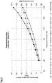
- FIG. 3 is the process parameter field temperature increase represented as a function of the mass flow of water.
- the second ordinate provides information about the service entry.
- This diagram thus shows the curve already described above FIG. 2 in relation to the right Y-axis together with two curves in which the energy input is achieved by means of another medium (steam, saturated, superheated, ...) (relative to the left Y-axis).
- the values for the amount of steam and the temperature reached are measured values. Therefore, they end at 140 ° C, which is a working temperature common to the present invention.
- the FIG. 3 illustrates that the introduction of defined amounts of medium at certain temperatures can replace the use of appropriate amounts of friction energy by the electric drive.
- a single-screw extruder 1 is constantly cold-fed with 100 kg / h of a dry tobacco product 3.
- the recipe requires conditioning with 15 kg / h of water.
- the crude product is in a first step before extrusion in a conditioner (not in FIG. 1 shown) treated with cold water.
- the conditioning with cold water is carried out directly in the extruder.
- the water 7 is heated to 250 ° C prior to entry into the extruder 1.
- the dosage requires the appropriate working pressure in the extruder 1 and, for example, a plunger pump 13 to achieve the feed conditions.
- Trial 3 consumed significantly less electric drive power, attributed to the circumstances listed above in the theoretical considerations (among others: possibility of relining, better efficiency of energy transfer to the tobacco material, lower clogging and rubbing effects).
- an advantageous extrusion for tobacco materials which uses the targeted introduction of enthalpy by a recipe-specific medium in order to save (electrical) energy. Furthermore, improved design options for apparatus design are provided.
Landscapes
- Life Sciences & Earth Sciences (AREA)
- Chemical & Material Sciences (AREA)
- Engineering & Computer Science (AREA)
- Food Science & Technology (AREA)
- Polymers & Plastics (AREA)
- Manufacture Of Tobacco Products (AREA)
Description
- Die vorliegende Erfindung betrifft ein Verfahren zur Herstellung eines Rauchproduktes aus einem Tabakmaterial, bei dem das Tabakmaterial durch mindestens einen Extrusionsprozess aufbereitet wird, sowie eine Vorrichtung zur Herstellung eines Rauchproduktes aus einem Tabakmaterial mit einem Extruder. Allgemein betrifft sie das technische Gebiet der Behandlung von Tabakmaterialien in einem Extruder.
- Bei vielen Extruder-Applikationen, insbesondere bei der Behandlung von stärke- und zellulosehaltigen Naturstoffen (Lebensmittel), ist die Konditionierung ein wesentlicher Schritt. Unter Konditionierung versteht man die Einstellung einer Verarbeitungsfeuchte mit Wasser oder Wasserdampf. Die Erledigung dieser notwendigen Aufgaben findet oftmals in vorgeschalteten Prozessen/Apparaten statt. Dabei wird die Fähigkeit der Naturstoffe ausgenutzt, Dampf bzw. Wasser schnell und gut penetriert aufzunehmen. Die Apparate werden dabei bei Umgebungsdruck betrieben.
- Bei einem anderen Standardverfahren werden oftmals vorgefeuchtete Materialien in den Extruder-Eintragsbereich dosiert. Die Vorfeuchtung beeinflusst die Rieselfähigkeit des Produktes negativ. Je nach Materialgröße bzw. Geometrie des Eintrags kann es zur Brückenbildung und damit zum Abriss des Speisemassenstroms führen.
- Die vorliegende Erfindung kann auf dem oben genannten Gebiet der Behandlung von Lebensmitteln im Allgemeinen, bzw. für Nahrungs- und Genussmittel Anwendung finden. Hierin wird aber das Gebiet der Tabakmaterial-Behandlung näher erörtert.
- Eine Tabakvorbereitung dient bei einer herkömmlichen Verfahrensweise im Wesentlichen zur Herstellung von faserförmigen Teilchen aus dem Rohprodukt durch einen Schneider. Die Extrusion bietet demgegenüber erhebliche Vorteile in der Tabakbehandlung verglichen mit den konventionellen Verfahrensschritten an; sie ist ein "Hochtemperatur-Kurzzeit-Prozess".
- In der folgenden Tabelle werden die Prozessbereiche der Tabakbehandlung gegenüber gestellt.
Extrusion Konventionelle Tabakvorbereitung Feuchte 20-25% ∼20-22% zum Schneiden ∼25-30% zum Trocknen Temperatur 120-150°C < 100°C Absolutdruck bis 200 bar Umgebungsdruck Bearbeitungszeit < 1 Minute > 10 Minuten - Während der Extrusion, insbesondere in Einwellen-Extrudern, werden die Materialien je nach Betriebsweise Scherkräften ausgesetzt, die zu einer erwünschten oder auch unerwünschten Erhitzung je nach sich einstellender Temperatur des Produktes führen (Scherenergieeintrag bis 0,1kwh/kg). Je nach Temperaturempfindlichkeit des Produkts muss ggf. der Prozess gekühlt werden. Der Transport des Materials im Extruder wird durch die Gesetzmäßigkeiten der Schlepp-, Druck- und Spaltströmung bestimmt. Der dissipative Energieeintrag wird vom Schneckenantrieb, also aus der Umsetzung von elektrischer Energie in Wärmeenergie, gespeist.
- In der
DE 10 2004 059 388 A1 und derDE 10 2005 006 117 A1 werden typische Tabakextrusionen beschrieben, bei denen das Tabakausgangsmaterial auf eine Temperatur von 60°C-180°C im Extruder durch Scherung erwärmt wird. Diese offenbarten Verfahren benutzen im Wesentlichen Elektroenergie zur Wärmeerzeugung. - Bekannt ist ferner eine Mantelbeheizung des Extruders, die allerdings nur geringe Wärmemengen austauschen kann, weil der Wärmewiderstand von Extruderinnenwand zur Tabakmasse klein und damit geschwindigkeitsbestimmend ist. Außerdem setzt die konvektive Temperierung einen hohen Füllungsgrad der Schecke voraus, was nicht immer gegeben ist.
- Die
WO 2006/061117 A1 ,WO 94/01007 A1 US 4,880,018 undUS 2005/0178398 A1 beschreiben ein Verfahren gemäß dem Oberbegriff des Anspruchs 1 bzw. eine Vorrichtung gemäß dem Oberbegriff des Anspruchs 6. - Die Erfindung hat sich zur Aufgabe gemacht, die Rauchproduktherstellung, die einen Extruder verwendet, zu optimieren, und zwar hauptsächlich in Hinsicht auf die Energieumsetzung. Insbesondere soll eine Herstellung ermöglicht werden, bei welcher eine Extrusion unter Verwendung eines Minimums an verbrauchter Elektroenergie möglich wird.
- Diese Aufgabe wird durch ein Verfahren gemäß dem Anspruch 1 und eine Vorrichtung gemäß dem Anspruch 6 gelöst. Die Unteransprüche definieren bevorzugte Ausführungsformen der Erfindung.
- Beim erfindungsgemäßen Verfahren zur Herstellung eines Rauchproduktes aus einem Tabakmaterial wird das Tabakmaterial durch mindestens einen Extrusionsprozess aufbereitet, welcher eine Verdichtung mit Druck- und Temperaturerhöhung sowie eine mechanische Bearbeitung und schlagartige Entspannungstrocknung des Materials an einem Auslass eines Extruders umfasst. Dem Tabakmaterial im Extruder wird zur Zuführung von Prozesswärme ein erwärmtes Prozessfluid als Wärmeträger zugeführt wird.
- Das Verfahren gemäß der vorliegenden Erfindung könnte in diesem Sinne auch als "thermische Extrusion" bezeichnet werden. Dabei soll der Begriff der "thermischen Extrusion" bei einer Variante eine Ausgestaltung bezeichnen, die bewusst durch Medien Enthalpie direkt in den Extruder einbringt. Die notwendige Temperaturerhöhung, die bisher unter anderem aufgrund von Reibung entstand, wird erfindungsgemäß direkt oder indirekt und mindestens teilweise durch andere Energieträger eingebracht. Dabei wird auch der aus heutiger Sicht nicht mehr zeitgemäße Verbrauch von elektrischer Energie zur Erhitzung minimiert bzw. eliminiert.
- Die Vorteile der beschriebenen Erfindung liegen nicht nur in der Verbesserung der Energiekostenbilanz. Ein zusätzlicher Vorteil der Erfindung zeigt sich in der Reduzierung der Baugröße von Motor, Getriebe und ggf. Frequenzumformer, was ebenfalls zur Kostenentlastung führt. Weiterhin wird die Übertragung des notwendigen Drehmoments verringert. Dadurch kann die Torsionssteifigkeit des Schneckenkernes herabgesetzt werden (e.g. Verringerung des Durchmessers bei gleichem Außendurchmesser). Diese Erkenntnis kann nutzbar umgesetzt werden, weil durch eine größere Kammertiefe der Schnecke eine Massenstromsteigerung durch erhöhtes "Schleppvolumen" bei gleichem Gehäusedurchmesser erreicht wird.
- Die Tabelle unten vergleicht die optimalen Betriebsweisen zum Eintrag von Energie in die Vorrichtung.
Energieeintrag durch Scherung Energieeintrag durch Konvektion Energieeintrag durch Medien Schneckenfüllung möglichst vollständig (überfüttert) nahezu vollständig teilgefüllt unterfüttert - In der täglichen Praxis wird die unterfütterte Betriebsweise bevorzugt, da Bereiche der teilgefüllten Schneckengänge im drucklosen Zustand vorliegen und die Gefahr der Verstopfung geringer ist. Dadurch ist es leicht möglich mit beispielsweise vorhandenem Wasserleitungsdruck (3 bar) die notwendige Wassermenge direkt einzubringen. Das Prozessfluid wird gemäß der Erfindung vor der Einbringung in den Extruder mittels einer dem Extruder beigeordneten Pumpe gefördert, wobei der Druck des Fluids im Wesentlichen auf den Extruderdruck an der Einbringstelle erhöht wird, speziell vor der Erwärmung.
- Erfindungsgemäß ist die Integration von betrieblich vorhandenen Wärmeträgern bzw. Fluiden, z.B. erwärmten Konditionierungsmitteln wie Dampf und Wasser von Vorteil, wobei das Prozessfluid vor der Einbringung in den Extruder in einem dem Extruder beigeordneten Erhitzer erwärmt werden kann.
- Vorteilhafterweise befindet sich das erwärmte Prozessfluid in einem der folgenden Zustände:
- Heißwasser, insbesondere knapp unterhalb des Siedepunktes beim herrschenden Druck;
- überhitztes Wasser, insbesondere in einem Temperaturbereich von mehr als 100 bis 350 °C, speziell 200 bis 300 ° und in einem Druckbereich von 50 bis 150 bar, speziell 80 bis 120 bar; oder
- überhitzter Dampf.
- Bar-Angaben betreffen Absolutdrücke.
- Das Prozessfluid kann bei steigender Extrudertemperatur mit steigendem Massenstrom in den Extruder eingebracht werden, speziell mit einem Massenstrom von 5 bis 60 kg/h, insbesondere 30 bis 45 kg/h.
- Die erfindungsgemäße Vorrichtung zur Herstellung eines Rauchproduktes aus einem Tabakmaterial hat einen Extruder, der eine Verdichtung eines Tabakmaterials mit Druck- und Temperaturerhöhung sowie eine mechanische Bearbeitung und schlagartige Entspannungstrocknung des Materials am Extruderauslass vornimmt. Dem Extruder ist ein Erhitzer beigeordnet, der ein Prozessfluid erwärmt, welches dem Extruder zur Zuführung von Prozesswärme als Wärmeträger zugeführt wird.
- Dabei wird dem Tabakmaterial zusätzlich (zu mechanischer und äußerer Erwärmung) Wärmeenergie zugeführt.
- Im Prozessfluid-Transportweg ist eine Pumpe angeordnet, die das Fluid fördert und den Druck des Fluids im Wesentlichen auf den Extruderdruck an der Einbringstelle erhöht. Die Pumpe kann im Prozessfluid-Transportweg vor dem Erhitzer und insbesondere hinter einem Fluidreservoir angeordnet sein.
- Die Erfindung wird im Weiteren anhand von Ausführungsformen und unter Bezugname auf die beiliegenden Zeichnungen näher erläutert. Sie kann alle hierin beschriebenen Merkmale einzeln sowie in jedweder sinnvollen Kombination umfassen und auch als Verwendung der hierin dargestellten Verfahrens- und Vorrichtungsvarianten auf dem Gebiet der Rauchproduktherstellung aufgefasst werden. In den beiliegenden Zeichnungen zeigen:
- Figur 1
- eine erfindungsgemäß ausgestaltete Vorrichtung für die Rauchproduktherstellung durch thermische Extrusion;
- Figur 2
- ein Diagramm, das die Energienutzung in einem Extruder veranschaulicht; und
- Figur 3
- ein Diagramm, das Temperaturerhöhung, Massenstrom und Leistungseintrag bei der thermischen Extrusion gegenüberstellt.
- Eine Vorrichtung zur Umsetzung der vorliegenden Erfindung ist in der
Figur 1 gezeigt. Der dargestellte Extruder 1 hat einen Antrieb 2 für eine im Gehäuse angebrachte Förderschnecke 6, mit der Tabakmaterial gefördert und verdichtet wird, welches an der mit 3 bezeichneten Stelle in den Extruder 1 eintritt. Die Schnecke 6 fördert und verdichtet dabei das Tabakmaterial, bis es rechts am Formwerkzeug 4ankommt, wo es beispielsweise durch einen sich öffnenden und schließenden Scherspalt ausgelassen wird, und dann als faseriges Extrudat 5 für die Rauchproduktfertigung zur Verfügung steht. Etwa in der Mitte der Vorrichtung wird erfindungsgemäß ein erwärmtes Prozessfluid 7 in den Extruder 1 eingebracht, wobei das Fluid 7 (beispielsweise erhitztes Wasser) vorher in einen Erhitzer 11 erwärmt worden ist, nachdem es mit einer Pumpe 13 aus einem Reservoir 15 gefördert wurde. - Bei der hier dargestellten Ausführungsform findet also eine direkte Einbringung von Konditioniermedium bzw. -fluid 7 (e.g. Wasser, Dampf) oder von anderen flüssigen Rezeptbestandteilen (Feuchthaltemitteln) in den Extruder 1 statt. Dabei kann das Fluid 7 bis unterhalb des Siedepunktes erhitzt werden, um mit einem Maximum an Enthalpie zum Prozess beizutragen. Der Siedepunkt richtet sich natürlich nach dem Prozessdruck; je höher der Prozessdruck, desto höher die mögliche Dosiertemperatur und der damit verbundene Enthalpieeintrag.
- Es soll nicht unerwähnt bleiben, dass die Dosierung von Wasser im Druckbereich die Möglichkeit schafft, den Prozess trotz Verschleißes der Schnecke 6 länger zu betreiben. Diese Beobachtung erklärt sich durch die schleichende Erhöhung des Füllungsgrades im Verschleißbetrieb der Schnecke 6. Dadurch werden immer größere Dosierdrücke seitens der Speisevorrichtung abverlangt. Eine verlängerte Standzeit hat erheblichen Einfluss auf die spezifischen Verschleißkosten des Prozesses und ist somit sehr attraktiv.
- Am Beispiel der
Figur 2 wird die Nutzung der elektrischen Energie in einem Extruder, aufgeteilt zwischen Reibungsarbeit (Temperaturerhöhung) und mechanischer Arbeit dargestellt. Das Diagramm zeigt auf welche elektrische Leistung in die Apparatur gesteckt werden muss, um bestimmte Temperaturen im Tabakprodukt zu erreichen. Dabei sind (wie auch in derFigur 3 ) die Parameter für den Tabakeintrag (100 kg/h) und die Verdichtung (100 bar) festgeschrieben. In der Grafik derFigur 2 wird getrennt aufgeführt welcher Anteil dem Transport der Tabakmenge durch die Vorrichtung zuzuschreiben ist und welcher Anteil durch innere Reibung in eine Temperaturerhöhung mündet. Es ist auffällig, dass der mechanische Energieeintrag, bestehend aus Leerlauf-, Kompressions- und Beschleunigungsarbeit in etwa konstant ist. DieFigur 2 verdeutlicht, dass bei einem Extrusionsprozess der Energieverbrauch je nach Prozessbedingung hauptsächlich zur Erhitzung benutzt wird. - In der
Figur 3 ist das Prozessparameterfeld Temperaturerhöhung als Funktion des Massenstroms Wasser dargestellt. Die zweite Ordinate gibt Auskunft über den Leistungseintrag. Dieses Diagramm zeigt also die oben schon beschriebene Kurve derFigur 2 bezogen auf die rechte Y-Achse zusammen mit zwei Kurven, bei denen der Energieeintrag mittels eines weiteren Mediums (Dampf, gesättigt, überhitzt, ...) erreicht wird (bezogen auf die linke Y-Achse). Die Werte für die Dampfmenge und die erreichte Temperatur sind gemessene Werte. Deshalb enden sie bei 140°C, was eine für die vorliegende Erfindung gebräuchliche Arbeitstemperatur ist. DieFigur 3 verdeutlicht also, dass die Einbringung definierter Mengen an Medium bei bestimmten Temperaturen den Einsatz von entsprechenden Mengen an Reibungsenergie durch den elektrischen Antrieb ersetzen können. Es ist also durchaus möglich, durch Einspeisung von 30 kg/h 300°C Wasser eine Mischtemperatur von ca. 130°C zu erreichen. Wenn mechanische Energieeinträge (Elektromotor) vermieden werden können, kann einerseits die gesamte Anlage schwächer und damit kostengünstiger konstruiert bzw. ausgelegt werden, andererseits besteht die Möglichkeit, eine Energieform zu verwenden, die billiger erzeugt werden kann. - Ein Einwellen-Extruder 1 wird konstant mit 100 kg/h eines trockenen Tabakproduktes 3 kalt gefüttert. Die Rezeptur verlangt eine Konditionierung mit 15 kg/h Wasser. Es werden drei Versuche zur Demonstration des erfindungsgemäßen Verfahrens in der Vorrichtung gemäß
Figur 1 (in Versuch 1 und 2 ohne Zuführung erhitzten Fluids 7) durchgeführt: - Das Rohprodukt wird in einem ersten Schritt vor der Extrusion in einem Konditionierer (nicht in
Figur 1 dargestellt) mit kaltem Wasser behandelt. - Die Konditionierung mit kaltem Wasser wird direkt im Extruder durchgeführt.
- Wiederholung des Versuchs 2, jedoch wird das Wasser 7 vor dem Eintrag in den Extruder 1 auf 250°C erhitzt. Die Dosierung setzt natürlich den entsprechenden Arbeitsdruck im Extruder 1 und beispielsweise eine Plungerpumpe 13 zum Erreichen der Einspeisebedingungen voraus.
- Die Extrusionsversuche wurden durchgeführt und die Leistungsaufnahme des Antriebes protokolliert. Die Versuche 1 und 2 zeigen eine ähnliche Leistungsaufnahme; wobei Versuch 2 tendenziell weniger Strom verbraucht. Das Resultat kann durch eine bessere Konditionierung (längere Verweilzeit) im Falle des Versuches 1 erklärt werden.
- Der Versuch 3 verbrauchte signifikant weniger elektrische Antriebsleistung, was den Umständen zugeschrieben wird, die oben bei den theoretischen Erwägungen aufgeführt wurden (unter anderem: Möglichkeit der Unterfütterung; besserer Wirkungsgrad bei der Energieübertragung auf das Tabakmaterial; geringere Verstopfungs- und Reibeffekte).
- Es wird ein demnach erfindungsgemäß eine vorteilhafte Extrusion für Tabakmaterialien bereitgestellt, welche den gezielten Eintrag von Enthalpie durch ein rezepturbestimmtes Medium nutzt, um (elektrische) Energie einzusparen. Ferner werden verbesserte konstruktive Möglichkeiten zur Apparateauslegung bereit gestellt.
Claims (7)
- Verfahren zur Herstellung eines Rauchproduktes aus einem Tabakmaterial bei dem das Tabakmaterial durch mindestens einen Extrusionsprozess aufbereitet wird, welcher eine Verdichtung mit Druck- und Temperaturerhöhung sowie eine mechanische Bearbeitung und schlagartige Entspannungstrocknung des Materials an einem Auslass eines Extruders (1) umfasst, wobei Prozesswärme dem Tabakmaterial im Extruder (1) als Enthalpie eines erwärmten Prozessfluids (7) als Wärmeträger zugeführt wird, dadurch gekennzeichnet, dass das Prozessfluid (7) vor der Einbringung in den Extruder (1) mittels einer dem Extruder (1) beigeordneten Pumpe (13) gefördert wird, wobei der Druck des Fluids im Wesentlichen auf den Extruderdruck an der Einbringstelle erhöht wird.
- Verfahren nach Anspruch 1, bei dem das Prozessfluid (7) vor der Einbringung in den Extruder (1) in einem dem Extruder beigeordneten Erhitzer (11) erwärmt wird.
- Verfahren nach einem der Ansprüche 1 oder 2, bei dem das Prozessfluid ein erwärmtes Konditionierungsmittel ist.
- Verfahren nach einem der Ansprüche 1 bis 3, bei dem das Prozessfluid erwärmtes Wasser oder Dampf ist, speziell in einem der folgenden Zustände:- Heißwasser, insbesondere knapp unterhalb des Siedepunktes beim herrschenden Druck;- überhitztes Wasser, insbesondere in einem Temperaturbereich von mehr als 100 bis 350 °C, speziell 200 bis 300 ° und in einem Druckbereich von 50 bis 150 bar, speziell 80 bis 120 bar;- überhitzter Dampf.
- Verfahren nach einem der Ansprüche 1 bis 4, bei dem das Prozessfluid bei steigender Extrudertemperatur mit steigendem Massenstrom in den Extruder eingebracht wird, insbesondere mit einem Massenstrom von 5 bis 60 kg/h, insbesondere 30 bis 45 kg/h.
- Vorrichtung zur Herstellung eines Rauchproduktes aus einem Tabakmaterial mit einem Extruder (1), der eine Verdichtung eines Tabakmaterials mit Druck- und Temperaturerhöhung sowie eine mechanische Bearbeitung und schlagartige Entspannungstrocknung des Materials am Extruderauslass vornimmt, wobei dem Extruder (1) ein Erhitzer (11) beigeordnet ist, der ein Prozessfluid (7) erwärmt, welches dem Extruder (1) zur Zuführung von Prozesswärme als Enthalpie zugeführt wird, dadurch gekennzeichnet, dass im Prozessfluid-Transportweg eine Pumpe (13) angeordnet ist, die das Fluid fördert und den Druck des Fluids im Wesentlichen auf den Extruderdruck an der Einbringstelle erhöht.
- Vorrichtung nach Anspruch 6, dadurch gekennzeichnet, dass die Pumpe (13) im Prozessfluid-Transportweg vor dem Erhitzer (11) und insbesondere hinter einem Fluidreservoir (15) angeordnet ist.
Applications Claiming Priority (2)
| Application Number | Priority Date | Filing Date | Title |
|---|---|---|---|
| DE102008059031A DE102008059031A1 (de) | 2008-11-26 | 2008-11-26 | Rauchproduktherstellung durch thermische Extrusion |
| PCT/EP2009/062049 WO2010060665A1 (de) | 2008-11-26 | 2009-09-17 | Rauchproduktherstellung durch thermische extrusion |
Publications (2)
| Publication Number | Publication Date |
|---|---|
| EP2367450A1 EP2367450A1 (de) | 2011-09-28 |
| EP2367450B1 true EP2367450B1 (de) | 2018-11-07 |
Family
ID=41328505
Family Applications (1)
| Application Number | Title | Priority Date | Filing Date |
|---|---|---|---|
| EP09783116.8A Active EP2367450B1 (de) | 2008-11-26 | 2009-09-17 | Rauchproduktherstellung durch thermische extrusion |
Country Status (16)
| Country | Link |
|---|---|
| US (1) | US8857075B2 (de) |
| EP (1) | EP2367450B1 (de) |
| JP (3) | JP5730773B2 (de) |
| KR (1) | KR101336175B1 (de) |
| CN (1) | CN102223814B (de) |
| AU (1) | AU2009319280B2 (de) |
| BR (1) | BRPI0919491B1 (de) |
| CA (1) | CA2733386C (de) |
| CL (1) | CL2011001135A1 (de) |
| DE (1) | DE102008059031A1 (de) |
| MX (1) | MX2011003492A (de) |
| MY (1) | MY169790A (de) |
| RU (1) | RU2524880C2 (de) |
| UA (1) | UA99786C2 (de) |
| WO (1) | WO2010060665A1 (de) |
| ZA (1) | ZA201101337B (de) |
Families Citing this family (4)
| Publication number | Priority date | Publication date | Assignee | Title |
|---|---|---|---|---|
| DE102008059031A1 (de) * | 2008-11-26 | 2010-05-27 | British American Tobacco (Germany) Gmbh | Rauchproduktherstellung durch thermische Extrusion |
| CN104856219B (zh) * | 2015-05-06 | 2017-01-04 | 湖北中烟工业有限责任公司 | 一种烟草制品挤压成型制备方法 |
| KR102767322B1 (ko) * | 2017-12-29 | 2025-02-14 | 필립모리스 프로덕츠 에스.에이. | 알칼로이드를 함유하는 균질화된 재료를 포함하는 시트의 제조 방법 및 그로부터 제조된 성분을 포함하는 에어로졸 형성 물품 |
| CN117137164B (zh) * | 2023-10-30 | 2024-01-19 | 云南旭众机械设备有限公司 | 一种操作便捷的半干湿米线机 |
Family Cites Families (17)
| Publication number | Priority date | Publication date | Assignee | Title |
|---|---|---|---|---|
| GB262989A (en) * | 1926-02-17 | 1926-12-23 | Sun Maid Raisin Growers Of Cal | Apparatus for heat treating raisins or other dried fruit |
| SU1227153A1 (ru) | 1984-11-26 | 1986-04-30 | Краснодарский ордена Трудового Красного Знамени политехнический институт | Способ изготовлени восстановленного табака |
| CN85205018U (zh) | 1985-11-23 | 1986-07-23 | 齐齐哈尔轻工学院 | 流化气力输送谷物连续膨化装置 |
| US4724850A (en) * | 1986-02-05 | 1988-02-16 | R. J. Reynolds Tobacco Company | Process for providing tobacco extender material |
| US4880018A (en) * | 1986-02-05 | 1989-11-14 | R. J. Reynolds Tobacco Company | Extruded tobacco materials |
| GB8704196D0 (en) * | 1987-02-23 | 1987-04-01 | British American Tobacco Co | Tobacco reconstitution |
| EP0326622A1 (de) * | 1988-01-30 | 1989-08-09 | Amandus Kahl Nachf. (GmbH & Co.) | Verfahren und Vorrichtung zur Steigerung des Nährstoffangebots und zur Verbesserung der Verträglichkeit von protein- und/oder stärkehaltigen Futter- und Nahrungsmitteln |
| DE4117329A1 (de) | 1991-05-27 | 1992-12-03 | Bat Cigarettenfab Gmbh | Trocknungsverfahren zur fuellfaehigkeitssteigerung von tabakmaterial und vorrichtung zur durchfuehrung dieses verfahrens |
| DE9208904U1 (de) * | 1992-07-03 | 1993-11-04 | Amandus Kahl GmbH & Co., 21465 Reinbek | Vorrichtung zum Verarbeitung von Rübenschnitzeln |
| BG98820A (en) * | 1993-06-14 | 1995-03-31 | Reynolds Tobacco Co R | Method and device for the expansion of tobacco |
| DE10065132A1 (de) * | 2000-12-29 | 2002-07-04 | Hauni Maschinenbau Ag | Verfahren zur Herstellung von Agglomeraten und entsprechendes Agglomerat |
| US7694686B2 (en) | 2003-12-22 | 2010-04-13 | U.S. Smokeless Tobacco Company | Conditioning process for tobacco and/or snuff compositions |
| PL1827142T3 (pl) | 2004-12-09 | 2011-11-30 | British American Tobacco Germany Gmbh | Rozwłóknianie materiału tytoniowego |
| DE102004059388B4 (de) * | 2004-12-09 | 2006-11-30 | British American Tobacco (Germany) Gmbh | Zerfaserung von Tabakmaterial |
| DE102005006117B4 (de) | 2005-02-10 | 2007-01-11 | British American Tobacco (Germany) Gmbh | Verarbeitung von Tabakmaterialien mit hohem Anteil an Tabakkleinteilen |
| RU2363358C1 (ru) | 2008-05-28 | 2009-08-10 | Олег Иванович Квасенков | Способ получения восстановленного табака |
| DE102008059031A1 (de) * | 2008-11-26 | 2010-05-27 | British American Tobacco (Germany) Gmbh | Rauchproduktherstellung durch thermische Extrusion |
-
2008
- 2008-11-26 DE DE102008059031A patent/DE102008059031A1/de not_active Ceased
-
2009
- 2009-09-17 BR BRPI0919491-6A patent/BRPI0919491B1/pt active IP Right Grant
- 2009-09-17 MX MX2011003492A patent/MX2011003492A/es active IP Right Grant
- 2009-09-17 UA UAA201106187A patent/UA99786C2/ru unknown
- 2009-09-17 RU RU2011117067/12A patent/RU2524880C2/ru active
- 2009-09-17 EP EP09783116.8A patent/EP2367450B1/de active Active
- 2009-09-17 US US13/130,609 patent/US8857075B2/en active Active
- 2009-09-17 WO PCT/EP2009/062049 patent/WO2010060665A1/de not_active Ceased
- 2009-09-17 KR KR1020117014835A patent/KR101336175B1/ko active Active
- 2009-09-17 AU AU2009319280A patent/AU2009319280B2/en not_active Ceased
- 2009-09-17 CN CN200980147077.9A patent/CN102223814B/zh not_active Expired - Fee Related
- 2009-09-17 CA CA2733386A patent/CA2733386C/en active Active
- 2009-09-17 JP JP2011537905A patent/JP5730773B2/ja active Active
- 2009-09-17 MY MYPI2011000581A patent/MY169790A/en unknown
-
2011
- 2011-02-18 ZA ZA2011/01337A patent/ZA201101337B/en unknown
- 2011-05-16 CL CL2011001135A patent/CL2011001135A1/es unknown
-
2013
- 2013-12-02 JP JP2013249102A patent/JP5913269B2/ja active Active
-
2016
- 2016-01-28 JP JP2016014702A patent/JP2016105720A/ja active Pending
Non-Patent Citations (1)
| Title |
|---|
| None * |
Also Published As
| Publication number | Publication date |
|---|---|
| ZA201101337B (en) | 2011-10-26 |
| JP2012509679A (ja) | 2012-04-26 |
| CA2733386C (en) | 2013-11-19 |
| MY169790A (en) | 2019-05-15 |
| AU2009319280B2 (en) | 2012-09-06 |
| CN102223814B (zh) | 2014-10-22 |
| US8857075B2 (en) | 2014-10-14 |
| CN102223814A (zh) | 2011-10-19 |
| BRPI0919491B1 (pt) | 2019-04-30 |
| MX2011003492A (es) | 2011-05-02 |
| KR101336175B1 (ko) | 2013-12-03 |
| WO2010060665A1 (de) | 2010-06-03 |
| RU2011117067A (ru) | 2013-01-10 |
| EP2367450A1 (de) | 2011-09-28 |
| CA2733386A1 (en) | 2010-06-03 |
| KR20110091562A (ko) | 2011-08-11 |
| AU2009319280A1 (en) | 2010-06-03 |
| JP5913269B2 (ja) | 2016-04-27 |
| RU2524880C2 (ru) | 2014-08-10 |
| JP2014076056A (ja) | 2014-05-01 |
| CL2011001135A1 (es) | 2012-07-06 |
| JP2016105720A (ja) | 2016-06-16 |
| UA99786C2 (ru) | 2012-09-25 |
| US20110283556A1 (en) | 2011-11-24 |
| JP5730773B2 (ja) | 2015-06-10 |
| BRPI0919491A2 (pt) | 2015-12-01 |
| DE102008059031A1 (de) | 2010-05-27 |
Similar Documents
| Publication | Publication Date | Title |
|---|---|---|
| DE102004034039B4 (de) | Extrusionsverfahren und Extruder für zellulosehaltiges Material | |
| EP2727477A2 (de) | Extraktive Tabakmaterial-Extrusion | |
| DE10050295A1 (de) | Mehrwellen-Extruder und Verfahren zur Aufbereitung und/oder Vorarbeitung von mit Füllstoff versetzten Elastomeren | |
| EP2367450B1 (de) | Rauchproduktherstellung durch thermische extrusion | |
| EP1127609B1 (de) | Verfahren zum Behandeln eines Produktes in zumindest einem Mischkneter | |
| US3638921A (en) | Apparatus for treating elastomeric materials | |
| EP3730275A2 (de) | Verfahren zur direktcompoundierung faserverstärkter verbundwerkstoffe für das herstellen von kunststoffformteilen und direktcompoundierungsvorrichtung | |
| EP2814654B2 (de) | SPRITZGIEßCOMPOUNDER UND VERRFAHREN | |
| DE10134701B4 (de) | Verfahren und Vorrichtung zur kontinuierlichen Herstellung von Kautschukmischungen | |
| DE2238532B2 (de) | Maschine zum behandeln von sojabohnen und aehnlichen erzeugnissen | |
| WO2004087391A1 (de) | Verfahren und vorrichtung zur plastifizierung von kunststoffmaterial | |
| EP2099322B1 (de) | Tabakzerfaserung mit zweiseitig gelagerter förderschneckenwelle | |
| DE102006001171A1 (de) | Extruder mit Materialeintrag durch Gehäuse und Entgasung | |
| DE102012112747B4 (de) | Plastifizierzylinder einer Spritzgießmaschine | |
| EP1027836A2 (de) | Verfahren und Vorrichtung zur Herstellung von Zwischenprodukten und Mischfutterprodukten für Tiere | |
| EP2111127B1 (de) | Hochdruckformgebung für tabakmaterial | |
| DE3716227A1 (de) | Verfahren zur herstellung von kakaopulveragglomeraten | |
| DE102011002279A1 (de) | Verfahren und Vorrichtung zur Herstellung einer Kautschukkomponente | |
| DE19913514C1 (de) | Verfahren und Vorrichtung zur Herstellung von Zwischenprodukten und Mischfutterfertigprodukten für Tiere | |
| DE102017005999A1 (de) | Herstellung von essbaren Wurstpellen aus Kollagen oder gleichartigen Stoffen durch Extrudieren | |
| DE10316119B4 (de) | Verfahren und Vorrichtung zur Herstellung eines Strangpressprofiles | |
| EP4324564B1 (de) | Verfahren zum zerkleinern von makroalgen | |
| EP3659773A1 (de) | Verfahren und vorrichtung zur aufbereitung einer styrol-acrylnitril-schmelze | |
| EP3976342A1 (de) | Verfahren zum herstellen einer extrudierten, schwefelvernetzbaren kautschukmischung und vorrichtung zur durchführung des verfahrens sowie deren verwendung | |
| DE4434252A1 (de) | Anlage zum Behandeln gemischter Kunsstoffabfälle |
Legal Events
| Date | Code | Title | Description |
|---|---|---|---|
| PUAI | Public reference made under article 153(3) epc to a published international application that has entered the european phase |
Free format text: ORIGINAL CODE: 0009012 |
|
| 17P | Request for examination filed |
Effective date: 20110523 |
|
| AK | Designated contracting states |
Kind code of ref document: A1 Designated state(s): AT BE BG CH CY CZ DE DK EE ES FI FR GB GR HR HU IE IS IT LI LT LU LV MC MK MT NL NO PL PT RO SE SI SK SM TR |
|
| DAX | Request for extension of the european patent (deleted) | ||
| RIN1 | Information on inventor provided before grant (corrected) |
Inventor name: SCHMEKEL, GERALD Inventor name: FRANKE, DIETMAR |
|
| 17Q | First examination report despatched |
Effective date: 20160509 |
|
| STAA | Information on the status of an ep patent application or granted ep patent |
Free format text: STATUS: EXAMINATION IS IN PROGRESS |
|
| REG | Reference to a national code |
Ref country code: DE Ref legal event code: R079 Ref document number: 502009015443 Country of ref document: DE Free format text: PREVIOUS MAIN CLASS: A24B0003180000 Ipc: A23P0030340000 |
|
| RIC1 | Information provided on ipc code assigned before grant |
Ipc: A23P 30/34 20160101AFI20180313BHEP Ipc: A24B 3/18 20060101ALI20180313BHEP |
|
| GRAP | Despatch of communication of intention to grant a patent |
Free format text: ORIGINAL CODE: EPIDOSNIGR1 |
|
| STAA | Information on the status of an ep patent application or granted ep patent |
Free format text: STATUS: GRANT OF PATENT IS INTENDED |
|
| INTG | Intention to grant announced |
Effective date: 20180420 |
|
| GRAS | Grant fee paid |
Free format text: ORIGINAL CODE: EPIDOSNIGR3 |
|
| GRAA | (expected) grant |
Free format text: ORIGINAL CODE: 0009210 |
|
| STAA | Information on the status of an ep patent application or granted ep patent |
Free format text: STATUS: THE PATENT HAS BEEN GRANTED |
|
| AK | Designated contracting states |
Kind code of ref document: B1 Designated state(s): AT BE BG CH CY CZ DE DK EE ES FI FR GB GR HR HU IE IS IT LI LT LU LV MC MK MT NL NO PL PT RO SE SI SK SM TR |
|
| REG | Reference to a national code |
Ref country code: GB Ref legal event code: FG4D Free format text: NOT ENGLISH |
|
| REG | Reference to a national code |
Ref country code: CH Ref legal event code: EP Ref country code: AT Ref legal event code: REF Ref document number: 1061037 Country of ref document: AT Kind code of ref document: T Effective date: 20181115 |
|
| REG | Reference to a national code |
Ref country code: IE Ref legal event code: FG4D Free format text: LANGUAGE OF EP DOCUMENT: GERMAN |
|
| REG | Reference to a national code |
Ref country code: DE Ref legal event code: R096 Ref document number: 502009015443 Country of ref document: DE |
|
| REG | Reference to a national code |
Ref country code: RO Ref legal event code: EPE |
|
| REG | Reference to a national code |
Ref country code: NL Ref legal event code: MP Effective date: 20181107 |
|
| REG | Reference to a national code |
Ref country code: LT Ref legal event code: MG4D |
|
| PG25 | Lapsed in a contracting state [announced via postgrant information from national office to epo] |
Ref country code: IS Free format text: LAPSE BECAUSE OF FAILURE TO SUBMIT A TRANSLATION OF THE DESCRIPTION OR TO PAY THE FEE WITHIN THE PRESCRIBED TIME-LIMIT Effective date: 20190307 Ref country code: BG Free format text: LAPSE BECAUSE OF FAILURE TO SUBMIT A TRANSLATION OF THE DESCRIPTION OR TO PAY THE FEE WITHIN THE PRESCRIBED TIME-LIMIT Effective date: 20190207 Ref country code: FI Free format text: LAPSE BECAUSE OF FAILURE TO SUBMIT A TRANSLATION OF THE DESCRIPTION OR TO PAY THE FEE WITHIN THE PRESCRIBED TIME-LIMIT Effective date: 20181107 Ref country code: ES Free format text: LAPSE BECAUSE OF FAILURE TO SUBMIT A TRANSLATION OF THE DESCRIPTION OR TO PAY THE FEE WITHIN THE PRESCRIBED TIME-LIMIT Effective date: 20181107 Ref country code: LV Free format text: LAPSE BECAUSE OF FAILURE TO SUBMIT A TRANSLATION OF THE DESCRIPTION OR TO PAY THE FEE WITHIN THE PRESCRIBED TIME-LIMIT Effective date: 20181107 Ref country code: HR Free format text: LAPSE BECAUSE OF FAILURE TO SUBMIT A TRANSLATION OF THE DESCRIPTION OR TO PAY THE FEE WITHIN THE PRESCRIBED TIME-LIMIT Effective date: 20181107 Ref country code: NO Free format text: LAPSE BECAUSE OF FAILURE TO SUBMIT A TRANSLATION OF THE DESCRIPTION OR TO PAY THE FEE WITHIN THE PRESCRIBED TIME-LIMIT Effective date: 20190207 Ref country code: LT Free format text: LAPSE BECAUSE OF FAILURE TO SUBMIT A TRANSLATION OF THE DESCRIPTION OR TO PAY THE FEE WITHIN THE PRESCRIBED TIME-LIMIT Effective date: 20181107 |
|
| PG25 | Lapsed in a contracting state [announced via postgrant information from national office to epo] |
Ref country code: PT Free format text: LAPSE BECAUSE OF FAILURE TO SUBMIT A TRANSLATION OF THE DESCRIPTION OR TO PAY THE FEE WITHIN THE PRESCRIBED TIME-LIMIT Effective date: 20190307 Ref country code: NL Free format text: LAPSE BECAUSE OF FAILURE TO SUBMIT A TRANSLATION OF THE DESCRIPTION OR TO PAY THE FEE WITHIN THE PRESCRIBED TIME-LIMIT Effective date: 20181107 Ref country code: GR Free format text: LAPSE BECAUSE OF FAILURE TO SUBMIT A TRANSLATION OF THE DESCRIPTION OR TO PAY THE FEE WITHIN THE PRESCRIBED TIME-LIMIT Effective date: 20190208 Ref country code: SE Free format text: LAPSE BECAUSE OF FAILURE TO SUBMIT A TRANSLATION OF THE DESCRIPTION OR TO PAY THE FEE WITHIN THE PRESCRIBED TIME-LIMIT Effective date: 20181107 |
|
| PG25 | Lapsed in a contracting state [announced via postgrant information from national office to epo] |
Ref country code: CZ Free format text: LAPSE BECAUSE OF FAILURE TO SUBMIT A TRANSLATION OF THE DESCRIPTION OR TO PAY THE FEE WITHIN THE PRESCRIBED TIME-LIMIT Effective date: 20181107 Ref country code: DK Free format text: LAPSE BECAUSE OF FAILURE TO SUBMIT A TRANSLATION OF THE DESCRIPTION OR TO PAY THE FEE WITHIN THE PRESCRIBED TIME-LIMIT Effective date: 20181107 Ref country code: PL Free format text: LAPSE BECAUSE OF FAILURE TO SUBMIT A TRANSLATION OF THE DESCRIPTION OR TO PAY THE FEE WITHIN THE PRESCRIBED TIME-LIMIT Effective date: 20181107 |
|
| REG | Reference to a national code |
Ref country code: DE Ref legal event code: R097 Ref document number: 502009015443 Country of ref document: DE |
|
| PG25 | Lapsed in a contracting state [announced via postgrant information from national office to epo] |
Ref country code: EE Free format text: LAPSE BECAUSE OF FAILURE TO SUBMIT A TRANSLATION OF THE DESCRIPTION OR TO PAY THE FEE WITHIN THE PRESCRIBED TIME-LIMIT Effective date: 20181107 Ref country code: SM Free format text: LAPSE BECAUSE OF FAILURE TO SUBMIT A TRANSLATION OF THE DESCRIPTION OR TO PAY THE FEE WITHIN THE PRESCRIBED TIME-LIMIT Effective date: 20181107 Ref country code: SK Free format text: LAPSE BECAUSE OF FAILURE TO SUBMIT A TRANSLATION OF THE DESCRIPTION OR TO PAY THE FEE WITHIN THE PRESCRIBED TIME-LIMIT Effective date: 20181107 |
|
| PLBE | No opposition filed within time limit |
Free format text: ORIGINAL CODE: 0009261 |
|
| STAA | Information on the status of an ep patent application or granted ep patent |
Free format text: STATUS: NO OPPOSITION FILED WITHIN TIME LIMIT |
|
| 26N | No opposition filed |
Effective date: 20190808 |
|
| PG25 | Lapsed in a contracting state [announced via postgrant information from national office to epo] |
Ref country code: SI Free format text: LAPSE BECAUSE OF FAILURE TO SUBMIT A TRANSLATION OF THE DESCRIPTION OR TO PAY THE FEE WITHIN THE PRESCRIBED TIME-LIMIT Effective date: 20181107 |
|
| PG25 | Lapsed in a contracting state [announced via postgrant information from national office to epo] |
Ref country code: TR Free format text: LAPSE BECAUSE OF FAILURE TO SUBMIT A TRANSLATION OF THE DESCRIPTION OR TO PAY THE FEE WITHIN THE PRESCRIBED TIME-LIMIT Effective date: 20181107 |
|
| PG25 | Lapsed in a contracting state [announced via postgrant information from national office to epo] |
Ref country code: MC Free format text: LAPSE BECAUSE OF FAILURE TO SUBMIT A TRANSLATION OF THE DESCRIPTION OR TO PAY THE FEE WITHIN THE PRESCRIBED TIME-LIMIT Effective date: 20181107 |
|
| REG | Reference to a national code |
Ref country code: CH Ref legal event code: PL |
|
| PG25 | Lapsed in a contracting state [announced via postgrant information from national office to epo] |
Ref country code: LU Free format text: LAPSE BECAUSE OF NON-PAYMENT OF DUE FEES Effective date: 20190917 Ref country code: IE Free format text: LAPSE BECAUSE OF NON-PAYMENT OF DUE FEES Effective date: 20190917 Ref country code: CH Free format text: LAPSE BECAUSE OF NON-PAYMENT OF DUE FEES Effective date: 20190930 Ref country code: LI Free format text: LAPSE BECAUSE OF NON-PAYMENT OF DUE FEES Effective date: 20190930 |
|
| REG | Reference to a national code |
Ref country code: BE Ref legal event code: MM Effective date: 20190930 |
|
| PG25 | Lapsed in a contracting state [announced via postgrant information from national office to epo] |
Ref country code: BE Free format text: LAPSE BECAUSE OF NON-PAYMENT OF DUE FEES Effective date: 20190930 |
|
| PG25 | Lapsed in a contracting state [announced via postgrant information from national office to epo] |
Ref country code: FR Free format text: LAPSE BECAUSE OF NON-PAYMENT OF DUE FEES Effective date: 20190930 |
|
| REG | Reference to a national code |
Ref country code: AT Ref legal event code: MM01 Ref document number: 1061037 Country of ref document: AT Kind code of ref document: T Effective date: 20190917 |
|
| PG25 | Lapsed in a contracting state [announced via postgrant information from national office to epo] |
Ref country code: AT Free format text: LAPSE BECAUSE OF NON-PAYMENT OF DUE FEES Effective date: 20190917 |
|
| PG25 | Lapsed in a contracting state [announced via postgrant information from national office to epo] |
Ref country code: CY Free format text: LAPSE BECAUSE OF FAILURE TO SUBMIT A TRANSLATION OF THE DESCRIPTION OR TO PAY THE FEE WITHIN THE PRESCRIBED TIME-LIMIT Effective date: 20181107 |
|
| PG25 | Lapsed in a contracting state [announced via postgrant information from national office to epo] |
Ref country code: MT Free format text: LAPSE BECAUSE OF FAILURE TO SUBMIT A TRANSLATION OF THE DESCRIPTION OR TO PAY THE FEE WITHIN THE PRESCRIBED TIME-LIMIT Effective date: 20181107 Ref country code: HU Free format text: LAPSE BECAUSE OF FAILURE TO SUBMIT A TRANSLATION OF THE DESCRIPTION OR TO PAY THE FEE WITHIN THE PRESCRIBED TIME-LIMIT; INVALID AB INITIO Effective date: 20090917 |
|
| PG25 | Lapsed in a contracting state [announced via postgrant information from national office to epo] |
Ref country code: MK Free format text: LAPSE BECAUSE OF FAILURE TO SUBMIT A TRANSLATION OF THE DESCRIPTION OR TO PAY THE FEE WITHIN THE PRESCRIBED TIME-LIMIT Effective date: 20181107 |
|
| P01 | Opt-out of the competence of the unified patent court (upc) registered |
Effective date: 20230504 |
|
| PGFP | Annual fee paid to national office [announced via postgrant information from national office to epo] |
Ref country code: GB Payment date: 20230920 Year of fee payment: 15 |
|
| GBPC | Gb: european patent ceased through non-payment of renewal fee |
Effective date: 20240917 |
|
| PG25 | Lapsed in a contracting state [announced via postgrant information from national office to epo] |
Ref country code: GB Free format text: LAPSE BECAUSE OF NON-PAYMENT OF DUE FEES Effective date: 20240917 |
|
| PGFP | Annual fee paid to national office [announced via postgrant information from national office to epo] |
Ref country code: DE Payment date: 20250919 Year of fee payment: 17 |
|
| PGFP | Annual fee paid to national office [announced via postgrant information from national office to epo] |
Ref country code: IT Payment date: 20250919 Year of fee payment: 17 |
|
| PGFP | Annual fee paid to national office [announced via postgrant information from national office to epo] |
Ref country code: RO Payment date: 20250910 Year of fee payment: 17 |