EP2364500B1 - Zugschaltervorrichtung - Google Patents
Zugschaltervorrichtung Download PDFInfo
- Publication number
- EP2364500B1 EP2364500B1 EP09771755.7A EP09771755A EP2364500B1 EP 2364500 B1 EP2364500 B1 EP 2364500B1 EP 09771755 A EP09771755 A EP 09771755A EP 2364500 B1 EP2364500 B1 EP 2364500B1
- Authority
- EP
- European Patent Office
- Prior art keywords
- casing
- pull switch
- light
- cord
- switch apparatus
- Prior art date
- Legal status (The legal status is an assumption and is not a legal conclusion. Google has not performed a legal analysis and makes no representation as to the accuracy of the status listed.)
- Not-in-force
Links
- 238000005286 illumination Methods 0.000 claims description 22
- 238000001514 detection method Methods 0.000 claims description 4
- 239000007787 solid Substances 0.000 claims description 3
- 238000013459 approach Methods 0.000 description 3
- 230000015572 biosynthetic process Effects 0.000 description 2
- 238000005755 formation reaction Methods 0.000 description 2
- 230000004308 accommodation Effects 0.000 description 1
- 239000011324 bead Substances 0.000 description 1
- 230000004300 dark adaptation Effects 0.000 description 1
- 230000004438 eyesight Effects 0.000 description 1
- 238000009428 plumbing Methods 0.000 description 1
- 230000005855 radiation Effects 0.000 description 1
- 239000000344 soap Substances 0.000 description 1
- 238000009423 ventilation Methods 0.000 description 1
- 230000002618 waking effect Effects 0.000 description 1
Images


Classifications
-
- H—ELECTRICITY
- H01—ELECTRIC ELEMENTS
- H01H—ELECTRIC SWITCHES; RELAYS; SELECTORS; EMERGENCY PROTECTIVE DEVICES
- H01H9/00—Details of switching devices, not covered by groups H01H1/00 - H01H7/00
- H01H9/18—Distinguishing marks on switches, e.g. for indicating switch location in the dark; Adaptation of switches to receive distinguishing marks
- H01H9/182—Illumination of the symbols or distinguishing marks
-
- H—ELECTRICITY
- H01—ELECTRIC ELEMENTS
- H01H—ELECTRIC SWITCHES; RELAYS; SELECTORS; EMERGENCY PROTECTIVE DEVICES
- H01H17/00—Switches having flexible operating part adapted only for pulling, e.g. cord, chain
- H01H17/02—Details
- H01H17/06—Movable parts
- H01H17/08—Operating part, e.g. cord
-
- H—ELECTRICITY
- H01—ELECTRIC ELEMENTS
- H01H—ELECTRIC SWITCHES; RELAYS; SELECTORS; EMERGENCY PROTECTIVE DEVICES
- H01H3/00—Mechanisms for operating contacts
- H01H3/02—Operating parts, i.e. for operating driving mechanism by a mechanical force external to the switch
- H01H3/022—Emergency operating parts, e.g. for stop-switch in dangerous conditions
- H01H3/0226—Emergency operating parts, e.g. for stop-switch in dangerous conditions operated by a pull cord
-
- F—MECHANICAL ENGINEERING; LIGHTING; HEATING; WEAPONS; BLASTING
- F21—LIGHTING
- F21S—NON-PORTABLE LIGHTING DEVICES; SYSTEMS THEREOF; VEHICLE LIGHTING DEVICES SPECIALLY ADAPTED FOR VEHICLE EXTERIORS
- F21S9/00—Lighting devices with a built-in power supply; Systems employing lighting devices with a built-in power supply
- F21S9/02—Lighting devices with a built-in power supply; Systems employing lighting devices with a built-in power supply the power supply being a battery or accumulator
-
- F—MECHANICAL ENGINEERING; LIGHTING; HEATING; WEAPONS; BLASTING
- F21—LIGHTING
- F21V—FUNCTIONAL FEATURES OR DETAILS OF LIGHTING DEVICES OR SYSTEMS THEREOF; STRUCTURAL COMBINATIONS OF LIGHTING DEVICES WITH OTHER ARTICLES, NOT OTHERWISE PROVIDED FOR
- F21V23/00—Arrangement of electric circuit elements in or on lighting devices
- F21V23/04—Arrangement of electric circuit elements in or on lighting devices the elements being switches
- F21V23/0442—Arrangement of electric circuit elements in or on lighting devices the elements being switches activated by means of a sensor, e.g. motion or photodetectors
Definitions
- This invention relates to pull switch apparatus, particularly to ceiling mounted pull switches which are conventionally used for safety reasons in domestic rooms where there is installed plumbing, for example bathrooms and toilets.
- Such pull switches are actuated by the user grasping and pulling down on a cord depending from the switch housing which is mounted on the ceiling. When actuated in this way, they turn the light(s) in the room in question on or off.
- a further difficulty in such circumstances is that the normal illumination instantly destroys the dark adaptation of the persons eyes, so that when they have finished using the room, and switch the light off using the pull switch, they are wholly unsighted and cannot immediately see where they are going.
- GB-A-2191634 discloses a pull switch apparatus consisting of a pull switch adapted to be mounted on a ceiling, a depending actuation cord, and, attached to the cord, a gripping member in the form of a casing having within it a power source, an illumination device, and switch means connected to the power source and the illumination device and adapted to cause the illumination device to be illuminated when the switch means is operated.
- the illumination is actuated when the casing is moved or when the casing is approached by a person.
- Motion activated lamps are known in a variety of embodiments, for example for illuminating the area around a door on the approach of a person and for so-called "security lights" designed to be mounted on the outside of buildings and to illuminate if a person approaches.
- a variety of motion activated lamps is known, for example as described in US-A-2008/0094827 and US-B-6729740 . Neither of these, however, is disclosed in combination with a pull switch.
- the pull switch which is located adjacent the entry door to a bathroom or toilet, the practical advantages obtained that the degree of illumination necessary is immediately provided to enable the person to see where they are going.
- This also contrasts with prior suggestions for bathroom night lights which use some other object in the bathroom, such as a soap dispenser ( US-A-2007/0007304 ) or associated with the toilet itself ( WO 95/25853 ) in order to provide the desired illumination.
- the illumination device is one or more light emitting diodes.
- the diodes may be mounted in the casing in any convenient fashion and arranged to emit low-level light when actuated to illuminate the surrounding area softly.
- the diodes may be protected from damage by being located behind a transparent or translucent window forming part of the casing.
- the power source within the casing is conveniently one or more battery cells, for example two or four AA or AAA size cells.
- the switching mechanism is also within the casing. While this may be essentially mechanical if it consists of a motion detector, it is more reliable to use a solid state motion detector or proximity detection switch, as there are then no moving parts which might give rise to problems such as wear or sticking.
- the life of the power supply may be increased if the casing includes an on/off switch enabling the automatic illumination feature to be turned off during the day or if another light source such as the main room light is on, or includes means (normally a light sensitive or photo transistor) to detect the ambient or surrounding levels of light, and arranged to ensure that if there is sufficient daylight, or a main light within the room is switched on, then the switching mechanism will not operate.
- the casing includes an on/off switch enabling the automatic illumination feature to be turned off during the day or if another light source such as the main room light is on, or includes means (normally a light sensitive or photo transistor) to detect the ambient or surrounding levels of light, and arranged to ensure that if there is sufficient daylight, or a main light within the room is switched on, then the switching mechanism will not operate.
- the shape of the casing may vary widely, but it is conveniently of a generally cylindrical shape which may be easily grasped and pulled down to operate the main illumination when needed. At night, simply moving it or putting a hand near it will cause the low level illumination to be provided from the casing.
- One end of the casing is adapted to receive the cord depending from the ceiling switch, for example taking the form of a screw-on end cap with a central small hole through which the cord is passed and then knotted before the end cap is replaced on the end of the housing. Unscrewing the end cap may give access to the battery compartment(s), or the casing itself may be configured with an access hatch and battery compartment, or be separable into two parts to give access to one or more cavities for the receipt of the battery cells.
- the end cap may incorporate a mechanism to enable quick release of the device from the cord to enable it to be used in an emergency as an emergency light, or as a safety light.
- This quick release mechanism could be in the form of a twist clip of two halves (either screwed together or incorporating a bayonet type fastening), one attached to the end cap, and one attached to the cord, or the end cap itself may be removable if not used as the cover for the battery compartment. This allows the device to be attached to, or released from the cord by a simple twisting action.
- the device may be inconvenient, for example, if the user puts the device down, that the time circuit causes a loss of illumination, so the device may also include an override switch which acts to cause the device to emit light continuously.
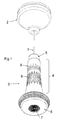
- FIG. 1 is a perspective view of switching apparatus according to the present invention seen from below;
- Figure 2 is a perspective view from above of the lower part of the apparatus shown in Figure 1 , separated into two parts;
- Figure 3 is a view similar to Figure 2 but showing the lower part of the apparatus separated at an alternative position;
- Figure 4 is a perspective view of half of the lower part of the apparatus shown in Figure 1 , as if longitudinally bisected;
- Figures 5 and 6 are perspective views of the two sides of a circuit board forming part of the apparatus.
- the pull grip 3 consists of a tapered generally cylindrical housing body 4 with an end cap 5 having a central hole through which cord 1 passes, and within which the end of cord 1 is knotted.
- the lower end of the housing carries a rotatable translucent or transparent cover 6 having a central portion in the form of a Fresnel lens 7.
- ceiling switch 2 By grasping the pull grip 3 and pulling it downwards, ceiling switch 2 may be actuated in known fashion.
- End cap 5 is connected to the upper portion of body 4 via a bayonet connection, so it may be disconnected from body 4 as shown in Figure 2 .
- Body 4 consists of two parts threaded together. Gripping formations 8 on body 4 enable the two parts to be easily separated or reassembled. When separated, as shown in Figure 3 , access to a battery compartment is provided.
- the cover 6 which may be clear or tinted, are four LEDs.
- a circuit and batteries arranged so that if the casing is moved, or if someone approaches it, the LEDs are supplied with current and light is emitted from cover 6.
- an internal switch By rotating the cover, an internal switch may be actuated to cause the LEDs to illuminate continuously.
- the range of rotation is shown by the two spaced moulded markings 9 on the cover and these can be registered with a moulded bead 10 on the bottom of body 4 at the limits of rotational movement of the cover 6.
- FIG. 4 shows the detailed configuration of the various parts, viz: end cap 5, main body 4 and cover 6. It also shows a circuit board assembly 14 including a motion sensor 15 and LEDs 16, and fixing screws 17 holding assembly 14 to the lower part of body 4. Located inside body 4 are four battery cells 18. The threaded connection between the two parts of body 4 is denoted 19.
- the motion sensor 15 is a pyroelectric infrared sensor (PIR) which detects relative motion (within a radius of about 2 metres) due to altering heat states such as that caused by a person moving within the locality of the device.
- PIR pyroelectric infrared sensor
- the 'range of vision' of sensor 15 is wide as it sits just above Fresnel lens 7.
- the triggering of sensor 15 causes a change in logic state within an integrated electronic circuit 22 mounted on the circuit board assembly.
- the circuit board assembly is shown in more detail in Figures 5 and 6 , with the tracks omitted for clarity.
- the board carries a sprung leaf 20 and cooperating contact post 21, battery contact studs 22, and a photoelectric light sensor 23.
- sensor 15 When sensor 15 detects incoming IR radiation, it causes the integrated circuit 22 to operate via solid state switching to supply a continuous current to the light- emitting diodes 16 so that they illuminate the area around the device.
- a timer circuit within the IC 22 will switch off the LEDs after a period of about 30 seconds of detecting no motion sensed by the PIR (when in the dark) and also within a period of up to 30 seconds of the detection of daylight or an additional light source such as the main room light being switched on by sensors 23. If this happens in the dark and while a user is still near the device, it can be reactivated by a simple movement within its 2 metre range e.g. by waving a hand.
- the unit may be detached from cord 1 by undoing the bayonet connection between the upper part of body 4 and cap 5 (leaving cap 5 on cord 1 so the cord can still be pulled down to operate switch 2 if desired), and cap 6 swivelled so that an internal formation 26 (shown in Figure 4 ) abuts spring leaf 20 and moves it into contact with post 21 to cause the LEDs 16 to illuminate continuously until cap 6 is swivelled back.
Landscapes
- Arrangement Of Elements, Cooling, Sealing, Or The Like Of Lighting Devices (AREA)
- Circuit Arrangement For Electric Light Sources In General (AREA)
Claims (15)
- Zugschaltervorrichtung, bestehend aus einem Zugschalter (2), der zur Befestigung an einer Decke ausgelegt ist, einem herabhängenden Auslösungskabel (1) und einem am Kabel (1) befestigten Greifelement (3) in der Form eines Gehäuses, das eine Stromquelle, eine Beleuchtungsreinrichtung und Schaltermittel darin aufweist, welche Schaltermittel mit der Stromquelle und der Beleuchtungseinrichtung verbunden sind, und gekennzeichnet durch Mittel, die so ausgelegt sind, dass sie bewirken, dass die Beleuchtungseinrichtung leuchtet, wenn das Gehäuse bewegt wird oder wenn sich eine Person dem Gehäuse nähert.
- Zugschaltervorrichtung gemäß Anspruch 1, wobei es sich bei der Beleuchtungseinrichtung um eine oder mehrere Leuchtdioden (16) handelt.
- Zugschaltervorrichtung gemäß Anspruch 2, wobei sich die Dioden hinter einem durchsichtigen oder durchscheinenden Fenster (6) befinden, das ein Teil des Gehäuses ist.
- Zugschaltervorrichtung gemäß einem der Ansprüche 1 bis 3, wobei die Sromquelle aus einer oder mehreren Batteriezellen (18) besteht.
- Zugschaltervorrichtung gemäß einem der vorhergehenden Ansprüche, wobei das Gehäuse einen Schaltmechanismus umfasst, der einen Festkörper-Bewegungsmelder (15) oder Näherungsmeldungsschalter umfasst, um zu bewirken, dass die Beleuchtungseinrichtung arbeitet.
- Zugschaltervorrichtung gemäß einem der vorhergehenden Ansprüche, wobei das Gehäuse einen Ein/Aus-Schalter (20, 21) aufweist, der es ermöglicht, dass die Auslösung der Beleuchtungseinrichtung deaktiviert wird.
- Zugschaltervorrichtung gemäß einem der vorhergehenden Ansprüche, wobei das Gehäuse eine im Allgemeinen zylindrische Form aufweist, welche leicht ergriffen und nach unten gezogen werden kann, um den Zugschalter zu betätigen.
- Zugschaltervorrichtung gemäß einem der vorhergehenden Ansprüche, wobei ein Ende des Gehäuses die Form einer anschraubbaren Endkappe (5) aufweist, die so ausgelegt ist, dass sie das vom Zugschalter (2) herabhängende Kabel (1) mit einem kleinen mittigen Loch aufnimmt, durch welches das Kabel durchtritt.
- Zugschaltervorrichtung gemäß Anspruch 8, wobei das Abschrauben der Endkappe (5) Zugang zum Batteriefach gewährt.
- Zugsehaltervorrichtung gemäß einem der vorhergehenden Ansprüche, wobei das Gehäuse eine Endkappe (5), an der das Auslösungskabel befestigt ist, und einen Mechanismus aufweist, der die Schnelllösung des Gehäuses vom Kabel ermöglicht, um seine Verwendung in einem Notfall als Notbeleuchtung oder Notlampe oder als Sicherheitsbeleuchtung zu ermöglichen.
- Zugschaltervorrichtung gemäß Anspruch 10, wobei der Mechanismus die Form eine Drehklamme mit zwei Hälften aufweist, die entweder zusammengeschraubt sind oder eine Bajonettbefestigung umfassen, wobei eine an der Endkappe (5) und eine am Kabel befestigt ist.
- Zugschaltergriff, bestehend aus einem länglichen Gehäuse, Mitteln (5) an einem Ende des Gehäuses zum Befestigen eines Zugschalters, und Mitteln (6, 7) am anderen Ende des Gehäuses zum Ausstrahlen von Licht, wobei das Gehäuse eine Stromquelle, einen Melder, der so ausgelegt ist, dass er meldet, wenn das Gehäuse bewegt wird oder wenn sich eine Person dem Gehäuse nähert, und Schaltermittel darin aufweist, welche Schaltermittel mit der Stromquelle, dem Melder und den Leuchtmitteln verbunden sind, und ausgelegt, um zu bewirken, dass die Leuchtmittel Licht ausstrahlen, wenn der Melder ausgelöst wird.
- Zugschaltergriff gemäß Anspruch 12, wobei es sich bei den Leuchtmitteln um eine oder mehrere Leuchtdioden (16) handelt.
- Zugschaltergriff gemäß Anspruch 12 oder 13, wobei das Gehäuse Mittel zum Desaktivieren der Auslösung der Mittel zum Ausstrahlen von Licht umfasst, wenn die Umgebungsbeleuchtung um die Einrichtung herum ein bestimmtes Niveau überschreitet.
- Zugschaltergriff gemäß einem der Ansprüche 12 bis 14, umfassend Schaltermittel (20, 21), um die Mittel zum Ausstrahlen von Licht zu befähigen, unabhängig von Umgebunsbeleuchtungsbedingungen oder Bewegungs- oder Näherungsmeldung betätigt zu werden.
Applications Claiming Priority (2)
| Application Number | Priority Date | Filing Date | Title |
|---|---|---|---|
| GB0818509A GB0818509D0 (en) | 2008-10-09 | 2008-10-09 | Pull switch apparatus |
| PCT/GB2009/051348 WO2010041081A1 (en) | 2008-10-09 | 2009-10-09 | Pull switch apparatus |
Publications (3)
| Publication Number | Publication Date |
|---|---|
| EP2364500A1 EP2364500A1 (de) | 2011-09-14 |
| EP2364500B1 true EP2364500B1 (de) | 2013-06-12 |
| EP2364500B8 EP2364500B8 (de) | 2013-07-24 |
Family
ID=40083750
Family Applications (1)
| Application Number | Title | Priority Date | Filing Date |
|---|---|---|---|
| EP09771755.7A Not-in-force EP2364500B8 (de) | 2008-10-09 | 2009-10-09 | Zugschaltervorrichtung |
Country Status (3)
| Country | Link |
|---|---|
| EP (1) | EP2364500B8 (de) |
| GB (1) | GB0818509D0 (de) |
| WO (1) | WO2010041081A1 (de) |
Families Citing this family (2)
| Publication number | Priority date | Publication date | Assignee | Title |
|---|---|---|---|---|
| GB2528294B (en) * | 2014-07-16 | 2017-04-26 | Sleeklight Ltd | A light assembly |
| CN206112733U (zh) * | 2016-11-09 | 2017-04-19 | 王建春 | 悬挂式灯泡灯改良结构 |
Family Cites Families (12)
| Publication number | Priority date | Publication date | Assignee | Title |
|---|---|---|---|---|
| DE1636660U (de) * | 1952-01-14 | 1952-04-03 | Aug Neimke Fa | Leuchtzugpendel. |
| DE7337037U (de) * | 1973-10-13 | 1974-05-22 | Dommeyer W | Leuchtpendel für Zugschalter |
| JPS60198003A (ja) | 1984-03-19 | 1985-10-07 | 西山 文雄 | 照明器具用発光つまみ |
| GB8614521D0 (en) | 1986-06-14 | 1986-07-23 | Knight T A | Locating position of switch in the dark |
| JP2564676Y2 (ja) * | 1992-01-10 | 1998-03-09 | ナイルス部品株式会社 | 照明灯のスイッチ作動具 |
| US5454056A (en) | 1994-01-03 | 1995-09-26 | Brothers; Harlan J. | Luminous pull-cord for electrical switch operation |
| WO1995025853A1 (en) | 1994-03-22 | 1995-09-28 | Alec Robinson | Night light |
| JPH11297119A (ja) | 1998-04-10 | 1999-10-29 | Suruga Co Ltd | スイッチコ−ド及び発光装置 |
| US6315431B1 (en) | 1999-08-30 | 2001-11-13 | Christopher Greedy | Pull chain with light |
| US6729740B1 (en) | 2002-11-27 | 2004-05-04 | David Gazard | Door knob night light |
| US20070007304A1 (en) | 2004-08-19 | 2007-01-11 | Bitton Mary K | Illuminated liquid soap dispenser |
| US7585092B2 (en) | 2006-10-20 | 2009-09-08 | Thomas Huffman | Motion-activated lamps |
-
2008
- 2008-10-09 GB GB0818509A patent/GB0818509D0/en not_active Ceased
-
2009
- 2009-10-09 EP EP09771755.7A patent/EP2364500B8/de not_active Not-in-force
- 2009-10-09 WO PCT/GB2009/051348 patent/WO2010041081A1/en not_active Ceased
Also Published As
| Publication number | Publication date |
|---|---|
| EP2364500B8 (de) | 2013-07-24 |
| GB0818509D0 (en) | 2008-11-19 |
| EP2364500A1 (de) | 2011-09-14 |
| WO2010041081A1 (en) | 2010-04-15 |
Similar Documents
| Publication | Publication Date | Title |
|---|---|---|
| US9445699B2 (en) | Low power toilet light illuminator and night light with photosensor activation | |
| US6729740B1 (en) | Door knob night light | |
| US20110241555A1 (en) | Changeable LED finials | |
| JP4278637B2 (ja) | フットライト付き冷蔵庫 | |
| EP2364500B1 (de) | Zugschaltervorrichtung | |
| KR101034365B1 (ko) | 발광다이오드 조명등 | |
| NL2002293C2 (en) | Emergency illumination device and method of operating an emergency illumination device. | |
| KR101344868B1 (ko) | 실내용 조명장치 | |
| KR20170073877A (ko) | 문고리 거치형 조명 장치 | |
| CN103115340A (zh) | 一种智能感应发光门把手 | |
| JP6114982B2 (ja) | 照明制御スイッチ | |
| JP6676685B2 (ja) | 開き戸及びレバーハンドル | |
| JP3161424U (ja) | センサーライト | |
| US11363698B2 (en) | Door hardware illumination device | |
| KR100778931B1 (ko) | 유아, 장애인용 자동조명스위치 | |
| JP6114983B2 (ja) | 照明制御スイッチ | |
| CN216716027U (zh) | 发光挂件 | |
| CN106224878A (zh) | 一种具有吹风功能的消防应急灯 | |
| JP6547952B2 (ja) | 照明制御スイッチ | |
| JP7146629B2 (ja) | 戸体 | |
| JP7139239B2 (ja) | 戸体 | |
| JP2005242487A (ja) | スイッチ器具 | |
| US20230265980A1 (en) | Convenient Courtesy Lighting (A.K.A Courtesy) | |
| KR101764814B1 (ko) | 시인성을 향상시키는 발광형 스위치장치 | |
| TWI593308B (zh) | 個人照明系統及其使用方法 |
Legal Events
| Date | Code | Title | Description |
|---|---|---|---|
| PUAI | Public reference made under article 153(3) epc to a published international application that has entered the european phase |
Free format text: ORIGINAL CODE: 0009012 |
|
| 17P | Request for examination filed |
Effective date: 20110509 |
|
| AK | Designated contracting states |
Kind code of ref document: A1 Designated state(s): AT BE BG CH CY CZ DE DK EE ES FI FR GB GR HR HU IE IS IT LI LT LU LV MC MK MT NL NO PL PT RO SE SI SK SM TR |
|
| DAX | Request for extension of the european patent (deleted) | ||
| GRAP | Despatch of communication of intention to grant a patent |
Free format text: ORIGINAL CODE: EPIDOSNIGR1 |
|
| GRAS | Grant fee paid |
Free format text: ORIGINAL CODE: EPIDOSNIGR3 |
|
| GRAA | (expected) grant |
Free format text: ORIGINAL CODE: 0009210 |
|
| AK | Designated contracting states |
Kind code of ref document: B1 Designated state(s): AT BE BG CH CY CZ DE DK EE ES FI FR GB GR HR HU IE IS IT LI LT LU LV MC MK MT NL NO PL PT RO SE SI SK SM TR |
|
| REG | Reference to a national code |
Ref country code: GB Ref legal event code: FG4D |
|
| REG | Reference to a national code |
Ref country code: CH Ref legal event code: EP |
|
| REG | Reference to a national code |
Ref country code: AT Ref legal event code: REF Ref document number: 616953 Country of ref document: AT Kind code of ref document: T Effective date: 20130615 |
|
| REG | Reference to a national code |
Ref country code: IE Ref legal event code: FG4D |
|
| REG | Reference to a national code |
Ref country code: DE Ref legal event code: R096 Ref document number: 602009016406 Country of ref document: DE Effective date: 20130808 |
|
| PG25 | Lapsed in a contracting state [announced via postgrant information from national office to epo] |
Ref country code: ES Free format text: LAPSE BECAUSE OF FAILURE TO SUBMIT A TRANSLATION OF THE DESCRIPTION OR TO PAY THE FEE WITHIN THE PRESCRIBED TIME-LIMIT Effective date: 20130923 Ref country code: GR Free format text: LAPSE BECAUSE OF FAILURE TO SUBMIT A TRANSLATION OF THE DESCRIPTION OR TO PAY THE FEE WITHIN THE PRESCRIBED TIME-LIMIT Effective date: 20130913 Ref country code: NO Free format text: LAPSE BECAUSE OF FAILURE TO SUBMIT A TRANSLATION OF THE DESCRIPTION OR TO PAY THE FEE WITHIN THE PRESCRIBED TIME-LIMIT Effective date: 20130912 Ref country code: LT Free format text: LAPSE BECAUSE OF FAILURE TO SUBMIT A TRANSLATION OF THE DESCRIPTION OR TO PAY THE FEE WITHIN THE PRESCRIBED TIME-LIMIT Effective date: 20130612 Ref country code: SI Free format text: LAPSE BECAUSE OF FAILURE TO SUBMIT A TRANSLATION OF THE DESCRIPTION OR TO PAY THE FEE WITHIN THE PRESCRIBED TIME-LIMIT Effective date: 20130612 Ref country code: SE Free format text: LAPSE BECAUSE OF FAILURE TO SUBMIT A TRANSLATION OF THE DESCRIPTION OR TO PAY THE FEE WITHIN THE PRESCRIBED TIME-LIMIT Effective date: 20130612 Ref country code: FI Free format text: LAPSE BECAUSE OF FAILURE TO SUBMIT A TRANSLATION OF THE DESCRIPTION OR TO PAY THE FEE WITHIN THE PRESCRIBED TIME-LIMIT Effective date: 20130612 |
|
| REG | Reference to a national code |
Ref country code: AT Ref legal event code: MK05 Ref document number: 616953 Country of ref document: AT Kind code of ref document: T Effective date: 20130612 |
|
| REG | Reference to a national code |
Ref country code: NL Ref legal event code: VDEP Effective date: 20130612 |
|
| REG | Reference to a national code |
Ref country code: LT Ref legal event code: MG4D |
|
| PG25 | Lapsed in a contracting state [announced via postgrant information from national office to epo] |
Ref country code: HR Free format text: LAPSE BECAUSE OF FAILURE TO SUBMIT A TRANSLATION OF THE DESCRIPTION OR TO PAY THE FEE WITHIN THE PRESCRIBED TIME-LIMIT Effective date: 20130612 Ref country code: BG Free format text: LAPSE BECAUSE OF FAILURE TO SUBMIT A TRANSLATION OF THE DESCRIPTION OR TO PAY THE FEE WITHIN THE PRESCRIBED TIME-LIMIT Effective date: 20130912 |
|
| PG25 | Lapsed in a contracting state [announced via postgrant information from national office to epo] |
Ref country code: LV Free format text: LAPSE BECAUSE OF FAILURE TO SUBMIT A TRANSLATION OF THE DESCRIPTION OR TO PAY THE FEE WITHIN THE PRESCRIBED TIME-LIMIT Effective date: 20130612 |
|
| PG25 | Lapsed in a contracting state [announced via postgrant information from national office to epo] |
Ref country code: CZ Free format text: LAPSE BECAUSE OF FAILURE TO SUBMIT A TRANSLATION OF THE DESCRIPTION OR TO PAY THE FEE WITHIN THE PRESCRIBED TIME-LIMIT Effective date: 20130612 Ref country code: IS Free format text: LAPSE BECAUSE OF FAILURE TO SUBMIT A TRANSLATION OF THE DESCRIPTION OR TO PAY THE FEE WITHIN THE PRESCRIBED TIME-LIMIT Effective date: 20131012 Ref country code: PT Free format text: LAPSE BECAUSE OF FAILURE TO SUBMIT A TRANSLATION OF THE DESCRIPTION OR TO PAY THE FEE WITHIN THE PRESCRIBED TIME-LIMIT Effective date: 20131014 Ref country code: EE Free format text: LAPSE BECAUSE OF FAILURE TO SUBMIT A TRANSLATION OF THE DESCRIPTION OR TO PAY THE FEE WITHIN THE PRESCRIBED TIME-LIMIT Effective date: 20130612 Ref country code: AT Free format text: LAPSE BECAUSE OF FAILURE TO SUBMIT A TRANSLATION OF THE DESCRIPTION OR TO PAY THE FEE WITHIN THE PRESCRIBED TIME-LIMIT Effective date: 20130612 Ref country code: BE Free format text: LAPSE BECAUSE OF FAILURE TO SUBMIT A TRANSLATION OF THE DESCRIPTION OR TO PAY THE FEE WITHIN THE PRESCRIBED TIME-LIMIT Effective date: 20130612 Ref country code: SK Free format text: LAPSE BECAUSE OF FAILURE TO SUBMIT A TRANSLATION OF THE DESCRIPTION OR TO PAY THE FEE WITHIN THE PRESCRIBED TIME-LIMIT Effective date: 20130612 |
|
| PG25 | Lapsed in a contracting state [announced via postgrant information from national office to epo] |
Ref country code: RO Free format text: LAPSE BECAUSE OF FAILURE TO SUBMIT A TRANSLATION OF THE DESCRIPTION OR TO PAY THE FEE WITHIN THE PRESCRIBED TIME-LIMIT Effective date: 20130612 Ref country code: PL Free format text: LAPSE BECAUSE OF FAILURE TO SUBMIT A TRANSLATION OF THE DESCRIPTION OR TO PAY THE FEE WITHIN THE PRESCRIBED TIME-LIMIT Effective date: 20130612 Ref country code: NL Free format text: LAPSE BECAUSE OF FAILURE TO SUBMIT A TRANSLATION OF THE DESCRIPTION OR TO PAY THE FEE WITHIN THE PRESCRIBED TIME-LIMIT Effective date: 20130612 |
|
| PLBE | No opposition filed within time limit |
Free format text: ORIGINAL CODE: 0009261 |
|
| STAA | Information on the status of an ep patent application or granted ep patent |
Free format text: STATUS: NO OPPOSITION FILED WITHIN TIME LIMIT |
|
| PG25 | Lapsed in a contracting state [announced via postgrant information from national office to epo] |
Ref country code: DK Free format text: LAPSE BECAUSE OF FAILURE TO SUBMIT A TRANSLATION OF THE DESCRIPTION OR TO PAY THE FEE WITHIN THE PRESCRIBED TIME-LIMIT Effective date: 20130612 |
|
| REG | Reference to a national code |
Ref country code: DE Ref legal event code: R119 Ref document number: 602009016406 Country of ref document: DE |
|
| 26N | No opposition filed |
Effective date: 20140313 |
|
| PG25 | Lapsed in a contracting state [announced via postgrant information from national office to epo] |
Ref country code: IT Free format text: LAPSE BECAUSE OF FAILURE TO SUBMIT A TRANSLATION OF THE DESCRIPTION OR TO PAY THE FEE WITHIN THE PRESCRIBED TIME-LIMIT Effective date: 20130612 |
|
| REG | Reference to a national code |
Ref country code: CH Ref legal event code: PL |
|
| GBPC | Gb: european patent ceased through non-payment of renewal fee |
Effective date: 20131009 |
|
| REG | Reference to a national code |
Ref country code: DE Ref legal event code: R097 Ref document number: 602009016406 Country of ref document: DE Effective date: 20140313 |
|
| REG | Reference to a national code |
Ref country code: DE Ref legal event code: R119 Ref document number: 602009016406 Country of ref document: DE Effective date: 20140501 |
|
| REG | Reference to a national code |
Ref country code: IE Ref legal event code: MM4A |
|
| PG25 | Lapsed in a contracting state [announced via postgrant information from national office to epo] |
Ref country code: CH Free format text: LAPSE BECAUSE OF NON-PAYMENT OF DUE FEES Effective date: 20131031 Ref country code: LI Free format text: LAPSE BECAUSE OF NON-PAYMENT OF DUE FEES Effective date: 20131031 Ref country code: GB Free format text: LAPSE BECAUSE OF NON-PAYMENT OF DUE FEES Effective date: 20131009 |
|
| REG | Reference to a national code |
Ref country code: FR Ref legal event code: ST Effective date: 20140630 |
|
| PG25 | Lapsed in a contracting state [announced via postgrant information from national office to epo] |
Ref country code: FR Free format text: LAPSE BECAUSE OF NON-PAYMENT OF DUE FEES Effective date: 20131031 Ref country code: DE Free format text: LAPSE BECAUSE OF NON-PAYMENT OF DUE FEES Effective date: 20140501 |
|
| PG25 | Lapsed in a contracting state [announced via postgrant information from national office to epo] |
Ref country code: IE Free format text: LAPSE BECAUSE OF NON-PAYMENT OF DUE FEES Effective date: 20131009 |
|
| PG25 | Lapsed in a contracting state [announced via postgrant information from national office to epo] |
Ref country code: SM Free format text: LAPSE BECAUSE OF FAILURE TO SUBMIT A TRANSLATION OF THE DESCRIPTION OR TO PAY THE FEE WITHIN THE PRESCRIBED TIME-LIMIT Effective date: 20130612 |
|
| PG25 | Lapsed in a contracting state [announced via postgrant information from national office to epo] |
Ref country code: TR Free format text: LAPSE BECAUSE OF FAILURE TO SUBMIT A TRANSLATION OF THE DESCRIPTION OR TO PAY THE FEE WITHIN THE PRESCRIBED TIME-LIMIT Effective date: 20130612 Ref country code: CY Free format text: LAPSE BECAUSE OF FAILURE TO SUBMIT A TRANSLATION OF THE DESCRIPTION OR TO PAY THE FEE WITHIN THE PRESCRIBED TIME-LIMIT Effective date: 20130612 |
|
| PG25 | Lapsed in a contracting state [announced via postgrant information from national office to epo] |
Ref country code: MC Free format text: LAPSE BECAUSE OF FAILURE TO SUBMIT A TRANSLATION OF THE DESCRIPTION OR TO PAY THE FEE WITHIN THE PRESCRIBED TIME-LIMIT Effective date: 20130612 Ref country code: HU Free format text: LAPSE BECAUSE OF FAILURE TO SUBMIT A TRANSLATION OF THE DESCRIPTION OR TO PAY THE FEE WITHIN THE PRESCRIBED TIME-LIMIT; INVALID AB INITIO Effective date: 20091009 Ref country code: LU Free format text: LAPSE BECAUSE OF NON-PAYMENT OF DUE FEES Effective date: 20131009 Ref country code: MK Free format text: LAPSE BECAUSE OF FAILURE TO SUBMIT A TRANSLATION OF THE DESCRIPTION OR TO PAY THE FEE WITHIN THE PRESCRIBED TIME-LIMIT Effective date: 20130612 |
|
| PG25 | Lapsed in a contracting state [announced via postgrant information from national office to epo] |
Ref country code: MT Free format text: LAPSE BECAUSE OF FAILURE TO SUBMIT A TRANSLATION OF THE DESCRIPTION OR TO PAY THE FEE WITHIN THE PRESCRIBED TIME-LIMIT Effective date: 20130612 |