EP2363520B1 - Verfahren und Vorrichtung zum Wechsel der Struktur bei der Herstellung wasserstrahlverfestigter, strukturierter Vliesstoffe - Google Patents
Verfahren und Vorrichtung zum Wechsel der Struktur bei der Herstellung wasserstrahlverfestigter, strukturierter Vliesstoffe Download PDFInfo
- Publication number
- EP2363520B1 EP2363520B1 EP20110000897 EP11000897A EP2363520B1 EP 2363520 B1 EP2363520 B1 EP 2363520B1 EP 20110000897 EP20110000897 EP 20110000897 EP 11000897 A EP11000897 A EP 11000897A EP 2363520 B1 EP2363520 B1 EP 2363520B1
- Authority
- EP
- European Patent Office
- Prior art keywords
- water jet
- structuring
- applicators
- elements
- speed
- Prior art date
- Legal status (The legal status is an assumption and is not a legal conclusion. Google has not performed a legal analysis and makes no representation as to the accuracy of the status listed.)
- Not-in-force
Links
- XLYOFNOQVPJJNP-UHFFFAOYSA-N water Substances O XLYOFNOQVPJJNP-UHFFFAOYSA-N 0.000 title claims description 44
- 238000000034 method Methods 0.000 title claims description 15
- 238000004519 manufacturing process Methods 0.000 title description 12
- 239000004744 fabric Substances 0.000 title 1
- 239000000463 material Substances 0.000 claims description 3
- 230000003213 activating effect Effects 0.000 claims 1
- 230000009849 deactivation Effects 0.000 claims 1
- 238000000605 extraction Methods 0.000 claims 1
- 239000004745 nonwoven fabric Substances 0.000 description 14
- 239000000835 fiber Substances 0.000 description 4
- 238000010924 continuous production Methods 0.000 description 3
- 238000012423 maintenance Methods 0.000 description 3
- 238000010276 construction Methods 0.000 description 2
- 238000013461 design Methods 0.000 description 2
- 238000005516 engineering process Methods 0.000 description 2
- 208000013201 Stress fracture Diseases 0.000 description 1
- 208000027418 Wounds and injury Diseases 0.000 description 1
- 238000007630 basic procedure Methods 0.000 description 1
- 238000009960 carding Methods 0.000 description 1
- 238000006243 chemical reaction Methods 0.000 description 1
- 238000007596 consolidation process Methods 0.000 description 1
- ZINJLDJMHCUBIP-UHFFFAOYSA-N ethametsulfuron-methyl Chemical compound CCOC1=NC(NC)=NC(NC(=O)NS(=O)(=O)C=2C(=CC=CC=2)C(=O)OC)=N1 ZINJLDJMHCUBIP-UHFFFAOYSA-N 0.000 description 1
- 230000003993 interaction Effects 0.000 description 1
- 238000000059 patterning Methods 0.000 description 1
- 230000002265 prevention Effects 0.000 description 1
- 238000007711 solidification Methods 0.000 description 1
- 230000008023 solidification Effects 0.000 description 1
- 239000002699 waste material Substances 0.000 description 1
Images







Classifications
-
- D—TEXTILES; PAPER
- D04—BRAIDING; LACE-MAKING; KNITTING; TRIMMINGS; NON-WOVEN FABRICS
- D04H—MAKING TEXTILE FABRICS, e.g. FROM FIBRES OR FILAMENTARY MATERIAL; FABRICS MADE BY SUCH PROCESSES OR APPARATUS, e.g. FELTS, NON-WOVEN FABRICS; COTTON-WOOL; WADDING ; NON-WOVEN FABRICS FROM STAPLE FIBRES, FILAMENTS OR YARNS, BONDED WITH AT LEAST ONE WEB-LIKE MATERIAL DURING THEIR CONSOLIDATION
- D04H1/00—Non-woven fabrics formed wholly or mainly of staple fibres or like relatively short fibres
- D04H1/40—Non-woven fabrics formed wholly or mainly of staple fibres or like relatively short fibres from fleeces or layers composed of fibres without existing or potential cohesive properties
- D04H1/44—Non-woven fabrics formed wholly or mainly of staple fibres or like relatively short fibres from fleeces or layers composed of fibres without existing or potential cohesive properties the fleeces or layers being consolidated by mechanical means, e.g. by rolling
- D04H1/46—Non-woven fabrics formed wholly or mainly of staple fibres or like relatively short fibres from fleeces or layers composed of fibres without existing or potential cohesive properties the fleeces or layers being consolidated by mechanical means, e.g. by rolling by needling or like operations to cause entanglement of fibres
- D04H1/492—Non-woven fabrics formed wholly or mainly of staple fibres or like relatively short fibres from fleeces or layers composed of fibres without existing or potential cohesive properties the fleeces or layers being consolidated by mechanical means, e.g. by rolling by needling or like operations to cause entanglement of fibres by fluid jet
- D04H1/495—Non-woven fabrics formed wholly or mainly of staple fibres or like relatively short fibres from fleeces or layers composed of fibres without existing or potential cohesive properties the fleeces or layers being consolidated by mechanical means, e.g. by rolling by needling or like operations to cause entanglement of fibres by fluid jet for formation of patterns, e.g. drilling or rearrangement
-
- D—TEXTILES; PAPER
- D04—BRAIDING; LACE-MAKING; KNITTING; TRIMMINGS; NON-WOVEN FABRICS
- D04H—MAKING TEXTILE FABRICS, e.g. FROM FIBRES OR FILAMENTARY MATERIAL; FABRICS MADE BY SUCH PROCESSES OR APPARATUS, e.g. FELTS, NON-WOVEN FABRICS; COTTON-WOOL; WADDING ; NON-WOVEN FABRICS FROM STAPLE FIBRES, FILAMENTS OR YARNS, BONDED WITH AT LEAST ONE WEB-LIKE MATERIAL DURING THEIR CONSOLIDATION
- D04H18/00—Needling machines
- D04H18/04—Needling machines with water jets
Definitions
- the invention relates to a method and a device for structuring hydroentangled nonwovens.
- the structuring of nonwovens by means of water jets is for example from DE 102005007757 A1 It describes a device for patterning and solidifying a nonwoven web.
- This device comprises a screen drum and a screen shell surrounding the screen drum from the outside.
- the fibers of the nonwoven material located on the sample shell are needled in accordance with the pattern formed by the holes of the sample shell by means of high-energy water jets.
- the pattern shell and the screen drum are connected by rapidly releasable mechanical means.
- DE 102005053168 B4 discloses a base drum for hydroentangling pulps or structuring drums with a topographical pattern on top and holes for pouring water.
- a microporous shell located on the drum during hydroentanglement is subjected to high mechanical stress due to the permanently walking motion, resulting in early fatigue fractures of the microporous shell.
- the holes in the shell of the base drum or structuring drum are configured as hexagonal shaped breakthroughs in addition to an increased accuracy of fit between the base drum and microporous shell and the shell of the drum has elevations on the webs between the hexagonal shaped openings on.
- teaching of this invention also does not permit a fully continuous production process if the pattern of structure to be incorporated into the web is to be changed.
- the production process must be stopped, opened the system and removed the structural shell. Subsequently, a new structural shell is placed on the existing holder, fastened and closed the system again. Now the production has to be started again, i. In addition to the loss of production time falls by the start from standstill and waste. If more frequent structural changes are required, the profitability of production is jeopardized.
- the object of the present invention is therefore to provide a method and a device which avoid the disadvantages of the prior art.
- This is first solidified in a solidification unit 11 by means of water jets. This is done by known methods, such as in the book “ Nonwovens ", Wiley Verlag, year 2000 on pages 326 to 340 described.
- the web 9, which is thus solidified and now has an inherent strength, is then fed to a structuring unit 12 designed according to the invention.
- the desired pattern is produced by means of water jet applicators 3 and the high-pressure water jets emerging therefrom in conjunction with a structuring element 5 on the initially non-patterned nonwoven fabric 9, so that it becomes the structured nonwoven fabric 4.
- the thus structured nonwoven 4 is dried in a dryer 13 and wound with a winder 14 into rolls.
- the structuring unit 12 contains at least two structuring elements 5 and 5 'and at least one, before and after a structuring element arranged, guide roller pair, in FIG. 3a as 1 and 1 ', and referred to as 2 and 2'.
- the structuring elements 5 and 5 'on a machine frame either as in FIG. 3a sequentially in succession or according to FIG. 4a be arranged on a rotatable holder.
- the roll main body is preferably in cantilever construction, i. only mounted on the drive side, executed.
- a support bearing mounted support bearing may be included in a device according to the invention.
- the guide roller pairs for example 1 and 1 ', arranged according to the invention before and after a structuring element 5, each consist of an upper roller and a lower roller between which the fleece is guided.
- the Leitwalzencrue for example, 1 and 1 ', are designed so that they are vertically displaceable.
- the wrap can also be less or go beyond 180 °.
- the self-immunity fleece 9 is guided so that it does not touch the structuring element 5 '.
- the inherent strength nonwoven fabric 9 wraps around the structuring element 5 with about 180 ° and is formed by the water jets 3 emerging from the water jets to the structured nonwoven fabric 4.
- the device according to the invention comprises at least one water jet applicator.
- the structuring elements are arranged sequentially one after the other.
- FIG. 3a By way of example, two successive structuring elements 5 and 5 ' shown, there may also be further structuring elements in the structuring unit 12.
- the Wasserstrahlapplikatoren 3 are designed so that they both vertically from working in Kir- or Verfahr too and horizontally from a working position, i. can be moved from one structuring element to the next.
- the system speed of the entire system is now reduced to changing speed. It is important that a ground speed, e.g. 20 m / min is not exceeded in order to prevent tearing of the fiber web at the web forming unit and to maintain the continuous production according to the invention.
- the water applicators 3 are deactivated, ie the water supply is interrupted so that the inherent strength nonwoven fabric 4 passes through the structuring element 5 without changing the surface. Furthermore, the suction 18 located within the structuring element 5 is deactivated.
- the water jet applicators 3 are according to Figure 3c now from the working position 7, ie the nozzle exit from the water jet applicator 3 is located between 10 and 20mm above the surface of the structure drum, moved into the passenger position 8.
- the distance between the nozzle outlet and the surface of the structure drum is to be selected according to the invention so that the entire water jet applicator 3 can be moved to a further structuring element 5 'without touching the guide roller pairs or the structuring units.
- the drive of the second structuring element 5 ' is started so that it runs at alternating speed.
- the Leitwalzencru 2 and 2 'of the second structuring element 5' is now moved from passenger position 8 in working position 7.
- the water jet applicator 3 is moved to the structuring element 5 '.
- the guide roller pair 1 and 1 'of the first structuring element 5 as in FIG. 3e represented driven in the passenger position 8 and the drive of the first structuring element 5 is deactivated.
- the water jet applicators 3 are according to FIG. 3f moved to the second structural element 5 'in working position 7.
- the structural shell 17 can now be removed and replaced on the maintenance side without any further interruption of the production process.
- ground speed e.g. 20 m / min is not exceeded in order to prevent tearing of the fiber web at the web forming unit and to maintain the continuous production according to the invention.
- the water applicators 3 are deactivated, that is to say the water supply is interrupted, so that the inherent strength nonwoven fabric 9 passes through the structuring element 5 without changing the surface. Furthermore, the suction 18 located within the structuring element 5 is deactivated, the pipe connection from the suction to the water treatment is released and a support bearing, if necessary, of the roller base body is opened.
- the water jet applicators 3 are according to Figure 4c now proceed from the working position 7 in the passenger position 8.
- the distance between the nozzle outlet and the surface of the structure drum is to be selected according to the invention so that the entire water jet applicator 3 can be moved to a position outside the range of rotation of the holder of the structuring elements 5 or 5 '.
- the structuring element 5 By rotating the support of the structuring elements, the structuring element 5 'is brought into the working position, as in FIGS Figures 4d and 4e shown.
- the suction of the structuring element 5 ' is connected to the pipeline, the eventually maintenance side existing support bearing for the roller body closed and the drive of the structuring element 5', and its suction are started.
- the drive on structuring element 5 is deactivated.
- the structural shell 17 can now be removed and replaced on the maintenance side without any further interruption of the production process.
- the pairs of guide rollers can be moved manually or electrically by means of a spindle from working to passenger position; pneumatically or hydraulically operated cylinders, which must be provided with a corresponding stroke, are applicable.
Landscapes
- Engineering & Computer Science (AREA)
- Textile Engineering (AREA)
- Mechanical Engineering (AREA)
- Nonwoven Fabrics (AREA)
Description
- Die Erfindung betrifft ein Verfahren und eine Vorrichtung zur Strukturierung von wasserstrahlverfestigten Vliesstoffen.
- Die Strukturierung von Vliesstoffen mittels Wasserstrahlen ist beispielsweise aus der
DE 102005007757 A1 bekannt, sie beschreibt eine Vorrichtung zur Musterung und Verfestigung einer Vliesstoffbahn. - Diese Vorrichtung umfasst eine Siebtrommel und eine die Siebtrommel von außen umschliessende Musterschale.
- Die auf der Musterschale befindlichen Fasem des Vliesmaterials werden dabei entsprechend dem durch die Löcher der Musterschale gebildeten Muster mittels energiereicher Wasserstrahlen vemadelt.
Die Musterschale und die Siebtrommel sind durch schnell lösbare mechanische Mittel miteinander verbunden. - Eine solch gestaltete Konstruktion macht es jedoch notwendig, dass zum Wechseln der Musterschale die Produktionsanlage abgestellt wird, damit der Umbau an der hier dargestellten Vorrichtung gemäß den vorgeschriebenen Unfallverhütungsvorschriften erfolgen kann.
- In
DE 102005053168 B4 wird eine Basistrommel für die Wasserstrahlverfestigung von Zellstoffen oder Strukturierungstrommel mit einem topographischen Muster auf der Oberseite und Löchern für das Abgießen von Wasser offenbart. - Eine während der Wasserstrahlverfestigung bzw. -strukturierung auf der Trommel befindliche mikroporöse Schale wird aufgrund der permanent walkenden Bewegung starker mechanischer Beanspruchung ausgesetzt, was zu frühen Ermüdungsbrüchen der mikroporösen Schale führt.
- Zur Erhöhung der Lebensdauer und Vereinfachung der Montage der mikroporösen Schale sind neben einer erhöhten Passgenauigkeit zwischen Basistrommel und mikroporöser Schale die Löcher in dem Mantel der Basistrommel oder Strukturierungstrommel als hexagonal geformte Durchbrüche ausgestaltet und der Mantel der Trommel weist auf den Stegen zwischen den hexagonal geformten Durchbrüchen Erhebungen auf.
- Dennoch ermöglicht die Lehre dieser Erfindung gleichfalls kein vollkontinuierliches Produktionsverfahren, wenn das in das Vlies einzubringende Strukturmuster geändert werden soll.
- Nach dem Stand der Technik muss daher zum Wechsel der Struktur, ob nun durch Schale oder Band erzeugt, der Produktionsprozess gestoppt, die Anlage geöffnet und die Strukturschale ausgebaut werden. Anschließend wird auf die vorhandene Halterung eine neue Strukturschale aufgesetzt, befestigt und die Anlage wieder geschlossen. Nun muss die Produktion wieder gestartet werden, d.h. neben dem Ausfall an Produktionszeit fällt durch das Anfahren aus dem Stillstand auch Abfall an. Stehen häufigere Strukturwechsel an, ist die Wirtschaftlichkeit der Herstellung gefährdet.
- Die Aufgabe der vorliegenden Erfindung ist es daher, ein Verfahren und eine Vorrichtung bereitzustellen, welche die Nachteile des Standes der Technik vermeiden.
- Die Aufgabe wird gemäß den Merkmalen der Ansprüche 1 bis gelöst. Eine erfindungsgemäße Vorrichtung ist in den Ansprüchen 5 bis beschrieben.
- Das erfindungsmäße Verfahren hat dabei folgenden, in
Figur 1 dargestellten prinzipiellen Ablauf: - In einer Vliesbildungseinheit 10 wird mittels bekannter Technologie, beispielsweise nach dem Kardierverfahren aus Stapelfasern oder nach dem Spinnvliesverfahren aus Filamenten, ein unverfestigter Faserflor hergestellt.
- Dieser wird in einer Verfestigungseinheit 11 zunächst mittels Wasserstrahlen verfestigt. Dies geschieht nach bekannten Verfahren, wie beispielsweise im Buch "Vliesstoffe", Wiley Verlag, Jahr 2000 auf den Seiten 326 bis 340 beschrieben.
- Das so verfestigte, nun eine Eigenfestigkeit aufweisende Vlies 9 wird dann einer erfindungsgemäß ausgeführten Strukturiereinheit 12 zugeführt.
- Innerhalb der Strukturierungseinheit 12 wird mittels Wasserstrahlapplikatoren 3 und den daraus austretenden Hochdruck-Wasserstrahlen in Verbindung mit einem Strukturierungselement 5 auf dem zunächst ungemusterten Vliesstoff 9 das gewünschte Muster erzeugt, sodass dieser zum strukturierten Vliesstoff 4 wird.
- Abschließend wird das so strukturierte Vlies 4 in einem Trockner 13 getrocknet und mit einem Wickler 14 zu Rollen aufgewickelt.
- Erfindungsgemäß enthält die Strukturiereinheit 12 mindestens zwei Strukturierungselemente 5 und 5' und mindestens ein, vor und nach einem Strukturierungselement angeordnetes, Leitwalzenpaar, in
Figur 3a als 1 und 1', sowie als 2 und 2' bezeichnet. - Erfindungsgemäß können die Strukturierungselemente 5 und 5' auf einem Maschinenrahmen entweder wie in
Figur 3a sequentiell hintereinander oder gemäßFigur 4a auf einer drehbaren Halterung angeordnet werden. - Der Einfachheit halber werden in den Figuren nur jeweils zwei Strukturierungselemente wiedergegeben. Es können aber auch noch weitere Elemente der jeweiligen erfindungsgemäßen Strukturierungseinheit hinzugefügt werden.
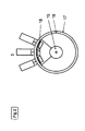
- Ein Strukturierungselement 5 setzt sich gemäß
Figur 2 prinzipiell zusammen aus - der Strukturschale 17, welche im Zusammenspiel mit den Wasserstrahlen das Muster auf dem Vliesstoff erzeugt
- der Basistrommel 16, auf welcher die Strukturschale befestigt ist,
- dem Walzengrundkörper 15, auf dem sich die Basistrommel 16 mit der Strukturschale 17 bewegt,
- der Absaugung 18, die antriebsseitig das aus den Wasserstrahlapplikatoren 3 durch das Vlies 9 gedrückte Wasser absaugt und zu einer Wasseraufbereitung weiterleitet und
- einem antriebsseitig befindlichen Antrieb
- Der Walzengrundkörper ist bevorzugt in Cantilever-Bauweise, d.h. nur auf der Antriebsseite gelagert, ausgeführt. Bei Arbeitsbreiten von größer 2m kann in einer erfindungsgemäßen Vorrichtung auch ein wartungsseitig angebrachtes Stützlager enthalten sein.
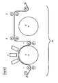
- Die erfindungsgemäß vor und nach einem Strukturierungselement 5 angeordneten Leitwalzenpaare, beispielsweise 1 und 1', bestehen jeweils aus einer Oberwalze und einer Unterwalze, zwischen denen das Vlies geführt wird. Die Leitwalzenpaare, beispielsweise 1 und 1', sind so ausgeführt, dass sie vertikal verschiebbar sind. Befinden die Leitwalzenpaare 1 und 1' wie in
Figur 3a dargestellt, in Arbeitsstellung 7, wird das Eigenfestigkeit aufweisende Vlies 9 so geführt, dass es das Strukturierungselement 5 auf ca 180°Umfang umschlingt. Je nach Ausführung der Vorrichtung und Anordnung, sowie Anzahl der Wasserstrahlapplikatoren kann die Umschlingung auch weniger betragen oder über 180° hinausgehen. - Befinden sich die die Leitwalzenpaare 2 und 2' wie
Figur 3a dargestellt in der Passagestellung 8, wird das Eigenfestigkeit aufweisende Vlies 9 so geführt, dass es das Strukturierungselement 5' nicht berührt. - Will man nun unter Verwendung einer erfindungsgemäß ausgelegten Strukturiereinheit von einer Struktur zur nächsten wechseln, ohne dazu die Produktion stoppen zu müssen, so sind erfindungsgemäß die nachfolgenden Verfahrensschritte auszuführen.
- Gemäß der Darstellung in
Figur 3a befinden sich bei laufender Produktion, d.h. bei Arbeitsgeschwindigkeit, am Strukturierungselement 5 die beiden Leitwalzenpaare 1 und 1' und die Wasserstrahlapplikatoren 3 in Arbeitsstellung 7. - Der Eigenfestigkeit aufweisende Vliesstoff 9 umschlingt das Strukturierungselement 5 mit ca 180° und wird durch die aus den Wasserstrahlapplikatoren 3 austretenden Wasserstrahlen zum strukturierten Vliesstoff 4. Die Vorrichtung weist dabei erfindungsgemäß mindestens einen Wasserstrahlapplikator auf.
- Die Leitwalzenpaare 2 und 2' befinden sich gemäß
Figur 3a bei laufender Produktion in Passagestellung, sodass der strukturierte Vliesstoff 4 um das Strukturierungselement 5' geführt wird, ohne dies zu berühren. - In einer bevorzugten erfindungsgemäßen Ausführungsform der Struktureinheit 12 sind die Strukturierungselemente sequentiell nacheinander angeordnet. In
Figur 3a werden beispielhaft zwei aufeinanderfolgende Strukturierungselemente 5 und 5' gezeigt, es können auch weitere noch Strukturierungselemente in der Strukturierungseinheit 12 vorhanden sein. - Die Wasserstrahlapplikatoren 3 sind so aus gelegt, dass sie sowohl vertikal von Arbeits- in Wechsel- oder Verfahrstellung als auch horizontal von einer Arbeitsposition, d.h. von einem Strukturierungselement zum nächsten verfahren werden können.
- Vor und nach einem Strukturierungselement 5 oder 5'sind erfindungsgemäß Leitwalzenpaare, in
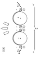
Figur 3a als 1 und 1' bzw 2 und 2'bezeichnet, angeordnet. - Zum Musterwechsel wird nun die Anlagengeschwindigkeit der Gesamtanlage auf Wechselgeschwindigkeit reduziert. Wichtig ist dabei, dass eine Grundgeschwindigkeit, z.B. 20m/min nicht unterschritten wird, um ein Abreißen des Faserflores an der Vliesbildungseinheit zu verhindern und die erfindungsgemäße, kontinuierliche Produktion aufrecht zu erhalten.
- Wie in
Figur 3b dargestellt werden als Nächstes die Wasserapplikatoren 3 deaktiviert, d.h. die Wasserversorgung wird unterbrochen, sodass der Eigenfestigkeit aufweisende Vliesstoff 4 ohne Änderung der Oberfläche durch das Strukturierungselement 5 läuft. Des Weiteren wird die sich innerhalb des Strukturierungselementes 5 befindliche Absaugung 18 deaktiviert. - Die Wasserstrahlapplikatoren 3 werden gemäß
Figur 3c nun von der Arbeitsposition 7, d.h. der Düsenaustritt vom Wasserstrahlapplikator 3 liegt zwischen 10 und 20mm über der Oberfläche der Strukturtrommel, in die Passagestellung 8 verfahren. - In Passagestellung 8 ist der Abstand zwischen Düsenaustritt und Oberfläche der Strukturtrommel ist erfindungsgemäß so zu wählen, dass der gesamte Wasserstrahlapplikator 3 zu einem weiteren Strukturierungselement 5' verfahren werden kann ohne die Leitwalzenpaare oder die Strukturierungseinheiten zu berühren.
- Im Anschluss daran wird der Antrieb des zweiten Strukturierungselementes 5'gestartet, sodass dieses mit Wechselgeschwindigkeit läuft. Wie in
Figur 3d dargestellt, wird das Leitwalzenpaar 2 und 2' des zweiten Strukturierungselementes 5' nun von Passagestellung 8 in Arbeitsstellung 7 verfahren. Der Wasserstrahlapplikator 3 wird zum Strukturierungslement 5' verfahren. - Nun wird erfindungsgemäß das Leitwalzenpaar 1 und 1' des ersten Strukturierungselementes 5 wie in
Figur 3e dargestellt in Passagestellung 8 gefahren und der Antrieb des ersten Strukturierungselementes 5 deaktiviert. - Die Wasserstrahlapplikatoren 3 werden gemäß
Figur 3f an dem zweiten Struktunerungselement 5' in Arbeitsstellung 7 gefahren. - Im Anschluss daran wird zunächst die Absaugung 18' innerhalb des zweiten Strukturierungselementes 5'und danach wie in
Figur 3g dargestellt, die Wasserstrahlapplikatoren 3 aktiviert. - Abschließend wird die Gesamtanlage wieder von Wechselgeschwindigkeit auf Arbeitsgeschwindigkeit beschleunigt.
- An dem deaktivierten Strukturierungslement 5 kann erfindungsgemäß nun ohne weitere Unterbrechung des Produktionsvorganges die Strukturschale 17 wartungsseitig abgezogen und ausgewechselt werden.
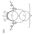
- In einen weiterem, besonders bevorzugten Verfahrensablauf zum unterbrechungsfreien Wechsel von einer Struktur zur anderen sind die Strukturierungseinheiten 5 und 5' auf einer drehbar gelagerten Halterung angebracht und die Wasserstrahlapplikatoren 3 sind lediglich vertikal verfahrbar.
- Zum Wechsel von einer Strukturierungseinheit zur anderen ist dabei erfindungsgemäß folgender Verfahrensablauf vorgesehen.
- Vor und nach einem Strukturierungselement 5 sind erfindungsgemäß Leitwalzenpaare, in den
Figuren 4a bis 4f als 1 und 1' bezeichnet, angeordnet. - Gemäß der Darstellung in
Figur 4a befinden sich bei laufender Produktion, d.h. bei Arbeitsgeschwindigkeit, am Strukturierungselement 5 - die beiden Leitwalzenpaare 1 und 1' und
- die Wasserstrahlapplikatoren 3
- in Arbeitsstellung 7. Der Eigenfestigkeit aufweisende Vliesstoff 9 umschlingt das Strukturierungsetement 5 mit ca 180° und wird durch die aus den Wasserstrahlapplikatoren 3 austretenden Wasserstrahlen zum strukturierten Vliesstoff 4.
- Zum Musterwechsel wird nun die Anlagengeschwindigkeit der Gesamtanlage auf Wechselgeschwindigkeit reduziert.
- Wichtig ist dabei, dass eine Grundgeschwindigkeit, z.B. 20m/min nicht unterschritten wird, um ein Abreißen des Faserflores an der Vliesbildungseinheit zu verhindern und die erfindungsgemäße, kontinuierliche Produktion aufrecht zu erhalten.
- Wie in
Figur 4b dargestellt werden als Nächstes die Wasserapplikatoren 3 deaktiviert, d.h. die Wasserversorgung wird unterbrochen, sodass der Eigenfestigkeit aufweisende Vliesstoff 9 ohne Änderung der Oberfläche durch das Strukturierungselement 5 läuft. Des Weiteren wird die sich innerhalb des Strukturierungselementes 5 befindliche Absaugung 18 deaktiviert, die Rohrverbindung von der Absaugung zur Wasseraufbereitung hin gelöst und ein ggf wartungsseitig befindliches Stützlager des Walzengrundkörpers geöffnet. - Die Wasserstrahlapplikatoren 3 werden gemäß
Figur 4c nun von der Arbeitsstellung 7 in die Passagestellung 8 verfahren. Der Abstand zwischen Düsenaustritt und Oberfläche der Strukturtrommel ist erfindungsgemäß so zu wählen, dass der gesamte Wasserstrahlapplikator 3 zu einer Position außerhalb des Drehbereichs der Halterung der Strukturierungselemente 5 bzw 5' verfahren werden kann. - Wie in
Figur 4c dargestellt, wird ebenso das Leitwalzenpaar 1 und 1' von Arbeitsstellung in eine Passagestellung außerhalb des Drehbereichs der Halterung der Strukturierungselemente 5 und 5' verfahren. Der Drehbereich der Strukturierungselemente 5 und 5' ist in denFiguren 4c bis 4e als Strich-Punkt-Linie dargestellt. - Durch Drehen der Halterung der Strukturierungselemente wird das Strukturierungselement 5' in Arbeitsposition gebracht, wie in den
Figuren 4d und4e gezeigt. - Die Absaugung des Strukturierungselements 5' wird mit der Rohrleitung verbunden, das eventuell wartungsseitig vorhandene Stützlager für den Walzengrundkörper geschlossen und der Antrieb des Strukturierungselements 5', sowie dessen Absaugung werden gestartet.
- Der Antrieb am Strukturierungselement 5 wird deaktivert.
- Gemäß
Figur 4f werden die Leitwalzenpaare 1 und 1' ebenso wie die Wasserstrahlapplikatoren 3 in Arbeitsstellung 7 verbracht. - Abschließend werden wie in
Figur 4g dargestellt, die Wasserstrahlapplikatoren 3 aktiviert und die Gesamtanlage wieder von Wechselgeschwindigkeit auf Arbeitsgeschwindigkeit beschleunigt. - An dem deaktivierten Strukturierungslement 5 kann erfindungsgemäß nun ohne weitere Unterbrechung des Produktionsvorganges die Strukturschale 17 wartungsseitig ausgebaut und gewechselt werden.
- Bei der Ausführung einer erfindungsgemäß ausgestalteten Vorrichtung können die Leitwalzenpaare manuell oder elektrisch mittels Spindel von Arbeits- in Passagestellung verfahren werden, anwendbar sind euch pneumatisch oder hydraulisch betriebene Zylinder, die mit entsprechendem Hub versehen sein müssen.
- Für die Auslegung der Führungen und Verstelleinheiten der Wasserstrahlapplikatoren 3 gilt prinzipiell die gleiche Vorgabe, jedoch ist bei diesen Aggregaten insbesondere auf Führung der Hochdruckwasserversorgung zu achten. Diese muss so ausgelegt sein, dass sie auch bei Arbeitsdrücken von bis zu 200 bar spannungsfrei läuft.
- 1 , 1'
- Leitwalzenpaar
- 2, 2'
- Leitwalzenpaar
- 3
- Wasserstrahlapplikatoren
- 4
- strukturiertes Vlies
- 5,5'
- Strukturierungselement
- 7
- Arbeitsstellung
- 8
- Passagestellung
- 9
- Verfestigtes, unstrukturiertes Vlies
- 10
- Vliesbildungseinheit
- 11
- Vliesverfestigung
- 12
- Strukturiereinheit
- 13
- Trockner
- 14
- Wickler
- 15
- Walzengrundkörper
- 16
- Basistrommel
- 17
- Strukturschale
- 18
- Absaugung
Claims (8)
- Verfahren zur Strukturierung von Eigenfestigkeit aufweisenden Vliesstoffen mittels Wasserstrahlen,
gekennzeichnet durch,- Kontinuierliches Führen des Vlieses über Leitwalzen und Strukturierungselemente bei Arbeitsgeschwindigkeit- Reduktion der Arbeitsgeschwindigkeit auf Wechselgeschwindigkeit unter Beibehaltung einer Grundgeschwindigkeit- Deaktivierung der Wasserstrahlapplikatoren und Verbringung in Passagestellung- Verbringung der Leitwalzen in Passagestellung- Tausch der Strukturierungselemente- Verbringung der Wasserstrahlapplikatoren und der Leitwalzen in Arbeitsstellung- Aktivieren der Wasserstrahlapplikatoren und Erhöhen von Wechselgeschwindigkeit auf Arbeitsgeschwindigkeit. - Verfahren nach Anspruch 1,
dadurch gekennzeichnet, dass
der Tausch der Strukturierungselemente durch Verfahren der Wasserstrahlapplikatoren von einer Arbeitsposition zu einer weiteren Arbeitsposition erreicht wird. - Verfahren nach Anspruch 1,
dadurch gekennzeichnet, dass
der Tausch der Strukturierungselemente innerhalb Arbeitsposition durch Drehen einer mit zwei oder mehreren Strukturierungselementen bestückten Halterung erreicht wird. - Strukturiereinheit zur Strukturierung von Eigenfestigkeit aufweisenden Vliesstoffen mittels Wasserstrahlen zur Verwendung innerhalb einer Wasserstrahlverfestigungsanlage umfassend Wasserstrahlapplikatoren und Strukturierungselemente, umfassend mindestens eine Strukturschale, eine Basistrommel, einen Walzengrundkörper, eine Absaugung und einen Antrieb,
dadurch gekennzeichnet, dass die Strukturiereinheit
mindestens zwei Strukturierungselemente,
mindestens ein Leitwalzenpaar und
mindestens einen Wasserstrahlapplikator
aufweist. - Vorrichtung nach Anspruch 4,
dadurch gekennzeichnet,
dass die Strukturierungselemente drehbar auf einer Halterung gelagert sind - Vorrichtung nach Anspruch 4,
dadurch gekennzeichnet,
dass die Strukturierungselemente sequentiell nacheinander angeordnet sind. - Vorrichtung nach Anspruch 4,
dadurch gekennzeichnet,
dass die Wasserstrahlapplikatoren vertikal und horizontal verfahrbar sind. - Vorrichtung nach Anspruch 4,
dadurch gekennzeichnet,
dass die Wasserstrahlapplikatoren vertikal verfahrbar sind
Applications Claiming Priority (1)
| Application Number | Priority Date | Filing Date | Title |
|---|---|---|---|
| DE201010009203 DE102010009203A1 (de) | 2010-02-24 | 2010-02-24 | Verfahren und Vorrichtung zum Wechsel der Struktur bei der Herstellung wasserstrahlverfestiger, strukturierter Vliesstoffe |
Publications (2)
| Publication Number | Publication Date |
|---|---|
| EP2363520A1 EP2363520A1 (de) | 2011-09-07 |
| EP2363520B1 true EP2363520B1 (de) | 2012-09-26 |
Family
ID=43754699
Family Applications (1)
| Application Number | Title | Priority Date | Filing Date |
|---|---|---|---|
| EP20110000897 Not-in-force EP2363520B1 (de) | 2010-02-24 | 2011-02-04 | Verfahren und Vorrichtung zum Wechsel der Struktur bei der Herstellung wasserstrahlverfestigter, strukturierter Vliesstoffe |
Country Status (2)
| Country | Link |
|---|---|
| EP (1) | EP2363520B1 (de) |
| DE (1) | DE102010009203A1 (de) |
Family Cites Families (8)
| Publication number | Priority date | Publication date | Assignee | Title |
|---|---|---|---|---|
| US7091140B1 (en) * | 1999-04-07 | 2006-08-15 | Polymer Group, Inc. | Hydroentanglement of continuous polymer filaments |
| FR2799214B1 (fr) * | 1999-10-05 | 2001-11-16 | Icbt Perfojet Sa | Procede pour la realisation de nappes non tissees dont la cohesion est obtenue par l'action de jets de fluide |
| DE10005306C1 (de) * | 2000-02-07 | 2001-06-13 | Kleinewefers Textilmaschinen G | Kalander, insbesondere für textile, Vlies- oder Kunststoff-Warenbahnen |
| DE10232148B4 (de) * | 2002-07-16 | 2009-01-08 | Fiberweb Corovin Gmbh | Verfahren zum flüssigkeitsdurchlässigen Perforieren eines Vlieses |
| DE102005007757A1 (de) | 2005-02-18 | 2006-08-31 | Fleissner Gmbh | Vorrichtung zur Musterung und Verfestigung einer Warenbahn mit austauschbarer Musterschale |
| DE102005053168B4 (de) | 2005-07-12 | 2009-02-19 | Saueressig Gmbh + Co. | Basistrommel oder Strukturierungstrommel und Verfahren zum Herstellen einer solchen Trommel |
| DE102008023922A1 (de) * | 2008-05-15 | 2009-11-19 | Fleissner Gmbh | Vorrichtung zur Beaufschlagung von flächigem Material mittels eines unter Druck stehenden Mediums |
| DE102008025237A1 (de) * | 2008-05-27 | 2009-12-03 | Fleissner Gmbh | Vorrichtung zur Beaufschlagung von flächigem Material mittels eines unter Druck stehenden Mediums |
-
2010
- 2010-02-24 DE DE201010009203 patent/DE102010009203A1/de not_active Withdrawn
-
2011
- 2011-02-04 EP EP20110000897 patent/EP2363520B1/de not_active Not-in-force
Also Published As
| Publication number | Publication date |
|---|---|
| EP2363520A1 (de) | 2011-09-07 |
| DE102010009203A1 (de) | 2011-08-25 |
Similar Documents
| Publication | Publication Date | Title |
|---|---|---|
| EP3504051B1 (de) | Vorrichtung und verfahren zur imprägnierung von faserstrukturen | |
| EP0792829B1 (de) | Verfahren zum Aufwickeln einer Papierbahn zu einer Rolle | |
| DE2900935C2 (de) | Verfahren und Vorrichtung zum Herstellen von Velour-Nadelvliesstoffbahnen | |
| EP3118361B1 (de) | Anlage und verfahren zur herstellung eines mehrschichtigen vlieses aus mindestens einem unverfestigtem faserflor | |
| EP2128320B1 (de) | Verfahren und Vorrichtung zur Herstellung von Spinnvliesen aus Filamenten | |
| DE69604399T2 (de) | Verfahren und vorrichtung zur herstellung von ringförmigen werkstücken aus verbundmaterial und vorformlinge für diese werkstücke | |
| WO2012098223A1 (de) | Vorrichtung sowie verfahren zum herstellen eines vlies-gewebeverbundes | |
| EP1223135B1 (de) | Vorrichtung zum Transport eines Vlieses zwischen zwei mit Abstand voneinander angeordneten Walzen | |
| EP4149751A1 (de) | Anlage und verfahren zur herstellung eines ein- oder mehrlagigen vlieses | |
| WO2009112015A1 (de) | Verfahren und vorrichtung zur herstellung eines vlieses | |
| DE4422844A1 (de) | Verfahren zum Vernadeln von Materialbahnen, dafür geeignete Vorrichtung und deren Verwendung | |
| EP3495543A1 (de) | Anlage und verfahren zur erzeugung eines spinnvlieses | |
| EP2363520A1 (de) | Verfahren und Vorrichtung zum Wechsel der Struktur bei der Herstellung wasserstrahlverfestigter, strukturierter Vliesstoffe | |
| DE2630514C2 (de) | Vorrichtung zum Herstellen von Samt, Velours o.dgl. aus einem Faservlies | |
| DE19929105A1 (de) | Verfahren und Vorrichtung zur Herstellung von strukturierten Vliesstoffen mittels hydrodynamischer Vernadelung | |
| WO1987006198A1 (fr) | Procede et dispositif pour apposer des lignes de marquage sur une bande de fibres minerales contenant un liant | |
| DE3712276C1 (en) | Fleece calender | |
| EP3604670A1 (de) | Vorrichtung zur entwässerung einer nassgelegten vliesstoffbahn | |
| DE202022106415U1 (de) | Faserbehandlungsanlage | |
| DE2263949A1 (de) | Nadelmaschine zur herstellung von polvliesen | |
| DE60011271T2 (de) | Verfahren und vorrichtung im prozess des aufwickels einer papierbahn | |
| EP1333123B1 (de) | Verfahren und Vorrichtung zur aktiven Dämpfung von Schwingungen in einer Vorrichtung zum Bearbeiten einer laufenden Bahn | |
| EP3536841B1 (de) | Anlage und verfahren zur erzeugung eines textilen velours | |
| DE2607147A1 (de) | Nadelmaschine zum herstellen endloser faservliese o.dgl. | |
| DE102013109251B3 (de) | Längsvliesleger und Verfahren zur Herstellung eines Vlieses |
Legal Events
| Date | Code | Title | Description |
|---|---|---|---|
| PUAI | Public reference made under article 153(3) epc to a published international application that has entered the european phase |
Free format text: ORIGINAL CODE: 0009012 |
|
| 17P | Request for examination filed |
Effective date: 20110217 |
|
| AK | Designated contracting states |
Kind code of ref document: A1 Designated state(s): AL AT BE BG CH CY CZ DE DK EE ES FI FR GB GR HR HU IE IS IT LI LT LU LV MC MK MT NL NO PL PT RO RS SE SI SK SM TR |
|
| AX | Request for extension of the european patent |
Extension state: BA ME |
|
| REG | Reference to a national code |
Ref country code: DE Ref legal event code: R079 Ref document number: 502011000113 Country of ref document: DE Free format text: PREVIOUS MAIN CLASS: D04H0001460000 Ipc: D04H0001495000 |
|
| RIC1 | Information provided on ipc code assigned before grant |
Ipc: D04H 1/495 20120101AFI20120601BHEP Ipc: D04H 18/04 20120101ALI20120601BHEP |
|
| GRAP | Despatch of communication of intention to grant a patent |
Free format text: ORIGINAL CODE: EPIDOSNIGR1 |
|
| GRAS | Grant fee paid |
Free format text: ORIGINAL CODE: EPIDOSNIGR3 |
|
| GRAA | (expected) grant |
Free format text: ORIGINAL CODE: 0009210 |
|
| AK | Designated contracting states |
Kind code of ref document: B1 Designated state(s): AL AT BE BG CH CY CZ DE DK EE ES FI FR GB GR HR HU IE IS IT LI LT LU LV MC MK MT NL NO PL PT RO RS SE SI SK SM TR |
|
| REG | Reference to a national code |
Ref country code: GB Ref legal event code: FG4D Free format text: NOT ENGLISH |
|
| REG | Reference to a national code |
Ref country code: CH Ref legal event code: EP |
|
| REG | Reference to a national code |
Ref country code: AT Ref legal event code: REF Ref document number: 577125 Country of ref document: AT Kind code of ref document: T Effective date: 20121015 |
|
| REG | Reference to a national code |
Ref country code: IE Ref legal event code: FG4D Free format text: LANGUAGE OF EP DOCUMENT: GERMAN |
|
| REG | Reference to a national code |
Ref country code: DE Ref legal event code: R096 Ref document number: 502011000113 Country of ref document: DE Effective date: 20121122 |
|
| PG25 | Lapsed in a contracting state [announced via postgrant information from national office to epo] |
Ref country code: HR Free format text: LAPSE BECAUSE OF FAILURE TO SUBMIT A TRANSLATION OF THE DESCRIPTION OR TO PAY THE FEE WITHIN THE PRESCRIBED TIME-LIMIT Effective date: 20120926 Ref country code: NO Free format text: LAPSE BECAUSE OF FAILURE TO SUBMIT A TRANSLATION OF THE DESCRIPTION OR TO PAY THE FEE WITHIN THE PRESCRIBED TIME-LIMIT Effective date: 20121226 Ref country code: FI Free format text: LAPSE BECAUSE OF FAILURE TO SUBMIT A TRANSLATION OF THE DESCRIPTION OR TO PAY THE FEE WITHIN THE PRESCRIBED TIME-LIMIT Effective date: 20120926 Ref country code: LT Free format text: LAPSE BECAUSE OF FAILURE TO SUBMIT A TRANSLATION OF THE DESCRIPTION OR TO PAY THE FEE WITHIN THE PRESCRIBED TIME-LIMIT Effective date: 20120926 |
|
| REG | Reference to a national code |
Ref country code: LT Ref legal event code: MG4D Effective date: 20120919 |
|
| REG | Reference to a national code |
Ref country code: NL Ref legal event code: VDEP Effective date: 20120926 |
|
| PG25 | Lapsed in a contracting state [announced via postgrant information from national office to epo] |
Ref country code: SI Free format text: LAPSE BECAUSE OF FAILURE TO SUBMIT A TRANSLATION OF THE DESCRIPTION OR TO PAY THE FEE WITHIN THE PRESCRIBED TIME-LIMIT Effective date: 20120926 Ref country code: SE Free format text: LAPSE BECAUSE OF FAILURE TO SUBMIT A TRANSLATION OF THE DESCRIPTION OR TO PAY THE FEE WITHIN THE PRESCRIBED TIME-LIMIT Effective date: 20120926 Ref country code: LV Free format text: LAPSE BECAUSE OF FAILURE TO SUBMIT A TRANSLATION OF THE DESCRIPTION OR TO PAY THE FEE WITHIN THE PRESCRIBED TIME-LIMIT Effective date: 20120926 |
|
| PG25 | Lapsed in a contracting state [announced via postgrant information from national office to epo] |
Ref country code: RO Free format text: LAPSE BECAUSE OF FAILURE TO SUBMIT A TRANSLATION OF THE DESCRIPTION OR TO PAY THE FEE WITHIN THE PRESCRIBED TIME-LIMIT Effective date: 20120926 Ref country code: NL Free format text: LAPSE BECAUSE OF FAILURE TO SUBMIT A TRANSLATION OF THE DESCRIPTION OR TO PAY THE FEE WITHIN THE PRESCRIBED TIME-LIMIT Effective date: 20120926 Ref country code: IS Free format text: LAPSE BECAUSE OF FAILURE TO SUBMIT A TRANSLATION OF THE DESCRIPTION OR TO PAY THE FEE WITHIN THE PRESCRIBED TIME-LIMIT Effective date: 20130126 Ref country code: EE Free format text: LAPSE BECAUSE OF FAILURE TO SUBMIT A TRANSLATION OF THE DESCRIPTION OR TO PAY THE FEE WITHIN THE PRESCRIBED TIME-LIMIT Effective date: 20120926 Ref country code: CZ Free format text: LAPSE BECAUSE OF FAILURE TO SUBMIT A TRANSLATION OF THE DESCRIPTION OR TO PAY THE FEE WITHIN THE PRESCRIBED TIME-LIMIT Effective date: 20120926 |
|
| PG25 | Lapsed in a contracting state [announced via postgrant information from national office to epo] |
Ref country code: PT Free format text: LAPSE BECAUSE OF FAILURE TO SUBMIT A TRANSLATION OF THE DESCRIPTION OR TO PAY THE FEE WITHIN THE PRESCRIBED TIME-LIMIT Effective date: 20130128 Ref country code: PL Free format text: LAPSE BECAUSE OF FAILURE TO SUBMIT A TRANSLATION OF THE DESCRIPTION OR TO PAY THE FEE WITHIN THE PRESCRIBED TIME-LIMIT Effective date: 20120926 Ref country code: SK Free format text: LAPSE BECAUSE OF FAILURE TO SUBMIT A TRANSLATION OF THE DESCRIPTION OR TO PAY THE FEE WITHIN THE PRESCRIBED TIME-LIMIT Effective date: 20120926 |
|
| PG25 | Lapsed in a contracting state [announced via postgrant information from national office to epo] |
Ref country code: RS Free format text: LAPSE BECAUSE OF FAILURE TO SUBMIT A TRANSLATION OF THE DESCRIPTION OR TO PAY THE FEE WITHIN THE PRESCRIBED TIME-LIMIT Effective date: 20120926 Ref country code: DK Free format text: LAPSE BECAUSE OF FAILURE TO SUBMIT A TRANSLATION OF THE DESCRIPTION OR TO PAY THE FEE WITHIN THE PRESCRIBED TIME-LIMIT Effective date: 20120926 Ref country code: BG Free format text: LAPSE BECAUSE OF FAILURE TO SUBMIT A TRANSLATION OF THE DESCRIPTION OR TO PAY THE FEE WITHIN THE PRESCRIBED TIME-LIMIT Effective date: 20121226 |
|
| PLBE | No opposition filed within time limit |
Free format text: ORIGINAL CODE: 0009261 |
|
| STAA | Information on the status of an ep patent application or granted ep patent |
Free format text: STATUS: NO OPPOSITION FILED WITHIN TIME LIMIT |
|
| PG25 | Lapsed in a contracting state [announced via postgrant information from national office to epo] |
Ref country code: IT Free format text: LAPSE BECAUSE OF FAILURE TO SUBMIT A TRANSLATION OF THE DESCRIPTION OR TO PAY THE FEE WITHIN THE PRESCRIBED TIME-LIMIT Effective date: 20120926 |
|
| BERE | Be: lapsed |
Owner name: SANDLER A.G. Effective date: 20130228 |
|
| 26N | No opposition filed |
Effective date: 20130627 |
|
| PG25 | Lapsed in a contracting state [announced via postgrant information from national office to epo] |
Ref country code: MC Free format text: LAPSE BECAUSE OF NON-PAYMENT OF DUE FEES Effective date: 20130228 |
|
| REG | Reference to a national code |
Ref country code: DE Ref legal event code: R097 Ref document number: 502011000113 Country of ref document: DE Effective date: 20130627 |
|
| PG25 | Lapsed in a contracting state [announced via postgrant information from national office to epo] |
Ref country code: ES Free format text: LAPSE BECAUSE OF FAILURE TO SUBMIT A TRANSLATION OF THE DESCRIPTION OR TO PAY THE FEE WITHIN THE PRESCRIBED TIME-LIMIT Effective date: 20130106 |
|
| PG25 | Lapsed in a contracting state [announced via postgrant information from national office to epo] |
Ref country code: CY Free format text: LAPSE BECAUSE OF FAILURE TO SUBMIT A TRANSLATION OF THE DESCRIPTION OR TO PAY THE FEE WITHIN THE PRESCRIBED TIME-LIMIT Effective date: 20120926 |
|
| REG | Reference to a national code |
Ref country code: IE Ref legal event code: MM4A |
|
| PG25 | Lapsed in a contracting state [announced via postgrant information from national office to epo] |
Ref country code: IE Free format text: LAPSE BECAUSE OF NON-PAYMENT OF DUE FEES Effective date: 20130204 Ref country code: AL Free format text: LAPSE BECAUSE OF FAILURE TO SUBMIT A TRANSLATION OF THE DESCRIPTION OR TO PAY THE FEE WITHIN THE PRESCRIBED TIME-LIMIT Effective date: 20120926 Ref country code: BE Free format text: LAPSE BECAUSE OF NON-PAYMENT OF DUE FEES Effective date: 20130228 |
|
| PG25 | Lapsed in a contracting state [announced via postgrant information from national office to epo] |
Ref country code: MT Free format text: LAPSE BECAUSE OF FAILURE TO SUBMIT A TRANSLATION OF THE DESCRIPTION OR TO PAY THE FEE WITHIN THE PRESCRIBED TIME-LIMIT Effective date: 20120926 |
|
| REG | Reference to a national code |
Ref country code: CH Ref legal event code: PL |
|
| PG25 | Lapsed in a contracting state [announced via postgrant information from national office to epo] |
Ref country code: LI Free format text: LAPSE BECAUSE OF NON-PAYMENT OF DUE FEES Effective date: 20140228 Ref country code: CH Free format text: LAPSE BECAUSE OF NON-PAYMENT OF DUE FEES Effective date: 20140228 |
|
| PG25 | Lapsed in a contracting state [announced via postgrant information from national office to epo] |
Ref country code: SM Free format text: LAPSE BECAUSE OF FAILURE TO SUBMIT A TRANSLATION OF THE DESCRIPTION OR TO PAY THE FEE WITHIN THE PRESCRIBED TIME-LIMIT Effective date: 20120926 |
|
| PG25 | Lapsed in a contracting state [announced via postgrant information from national office to epo] |
Ref country code: TR Free format text: LAPSE BECAUSE OF FAILURE TO SUBMIT A TRANSLATION OF THE DESCRIPTION OR TO PAY THE FEE WITHIN THE PRESCRIBED TIME-LIMIT Effective date: 20120926 |
|
| PG25 | Lapsed in a contracting state [announced via postgrant information from national office to epo] |
Ref country code: HU Free format text: LAPSE BECAUSE OF FAILURE TO SUBMIT A TRANSLATION OF THE DESCRIPTION OR TO PAY THE FEE WITHIN THE PRESCRIBED TIME-LIMIT; INVALID AB INITIO Effective date: 20110204 Ref country code: LU Free format text: LAPSE BECAUSE OF NON-PAYMENT OF DUE FEES Effective date: 20130204 Ref country code: MK Free format text: LAPSE BECAUSE OF FAILURE TO SUBMIT A TRANSLATION OF THE DESCRIPTION OR TO PAY THE FEE WITHIN THE PRESCRIBED TIME-LIMIT Effective date: 20120926 |
|
| PG25 | Lapsed in a contracting state [announced via postgrant information from national office to epo] |
Ref country code: GR Free format text: LAPSE BECAUSE OF NON-PAYMENT OF DUE FEES Effective date: 20120926 |
|
| GBPC | Gb: european patent ceased through non-payment of renewal fee |
Effective date: 20150204 |
|
| REG | Reference to a national code |
Ref country code: FR Ref legal event code: PLFP Year of fee payment: 6 |
|
| PG25 | Lapsed in a contracting state [announced via postgrant information from national office to epo] |
Ref country code: GB Free format text: LAPSE BECAUSE OF NON-PAYMENT OF DUE FEES Effective date: 20150204 |
|
| REG | Reference to a national code |
Ref country code: FR Ref legal event code: PLFP Year of fee payment: 7 |
|
| REG | Reference to a national code |
Ref country code: AT Ref legal event code: MM01 Ref document number: 577125 Country of ref document: AT Kind code of ref document: T Effective date: 20160204 |
|
| PG25 | Lapsed in a contracting state [announced via postgrant information from national office to epo] |
Ref country code: AT Free format text: LAPSE BECAUSE OF NON-PAYMENT OF DUE FEES Effective date: 20160204 |
|
| REG | Reference to a national code |
Ref country code: FR Ref legal event code: PLFP Year of fee payment: 8 |
|
| PGFP | Annual fee paid to national office [announced via postgrant information from national office to epo] |
Ref country code: DE Payment date: 20220211 Year of fee payment: 12 |
|
| PGFP | Annual fee paid to national office [announced via postgrant information from national office to epo] |
Ref country code: FR Payment date: 20220225 Year of fee payment: 12 |
|
| REG | Reference to a national code |
Ref country code: DE Ref legal event code: R119 Ref document number: 502011000113 Country of ref document: DE |
|
| PG25 | Lapsed in a contracting state [announced via postgrant information from national office to epo] |
Ref country code: FR Free format text: LAPSE BECAUSE OF NON-PAYMENT OF DUE FEES Effective date: 20230228 Ref country code: DE Free format text: LAPSE BECAUSE OF NON-PAYMENT OF DUE FEES Effective date: 20230901 |