EP2361873B1 - Verfahren und Vorrichtung zum sterilen Abfüllen von zwei unterschiedlichen Produktströmen in einen Behälter - Google Patents
Verfahren und Vorrichtung zum sterilen Abfüllen von zwei unterschiedlichen Produktströmen in einen Behälter Download PDFInfo
- Publication number
- EP2361873B1 EP2361873B1 EP11150972.5A EP11150972A EP2361873B1 EP 2361873 B1 EP2361873 B1 EP 2361873B1 EP 11150972 A EP11150972 A EP 11150972A EP 2361873 B1 EP2361873 B1 EP 2361873B1
- Authority
- EP
- European Patent Office
- Prior art keywords
- product
- product flow
- product stream
- flow
- filling valve
- Prior art date
- Legal status (The legal status is an assumption and is not a legal conclusion. Google has not performed a legal analysis and makes no representation as to the accuracy of the status listed.)
- Not-in-force
Links
Images
Classifications
-
- B—PERFORMING OPERATIONS; TRANSPORTING
- B67—OPENING, CLOSING OR CLEANING BOTTLES, JARS OR SIMILAR CONTAINERS; LIQUID HANDLING
- B67C—CLEANING, FILLING WITH LIQUIDS OR SEMILIQUIDS, OR EMPTYING, OF BOTTLES, JARS, CANS, CASKS, BARRELS, OR SIMILAR CONTAINERS, NOT OTHERWISE PROVIDED FOR; FUNNELS
- B67C3/00—Bottling liquids or semiliquids; Filling jars or cans with liquids or semiliquids using bottling or like apparatus; Filling casks or barrels with liquids or semiliquids
- B67C3/02—Bottling liquids or semiliquids; Filling jars or cans with liquids or semiliquids using bottling or like apparatus
- B67C3/22—Details
- B67C3/26—Filling-heads; Means for engaging filling-heads with bottle necks
-
- B—PERFORMING OPERATIONS; TRANSPORTING
- B65—CONVEYING; PACKING; STORING; HANDLING THIN OR FILAMENTARY MATERIAL
- B65B—MACHINES, APPARATUS OR DEVICES FOR, OR METHODS OF, PACKAGING ARTICLES OR MATERIALS; UNPACKING
- B65B3/00—Packaging plastic material, semiliquids, liquids or mixed solids and liquids, in individual containers or receptacles, e.g. bags, sacks, boxes, cartons, cans, or jars
- B65B3/04—Methods of, or means for, filling the material into the containers or receptacles
- B65B3/06—Methods of, or means for, filling the material into the containers or receptacles by gravity flow
-
- B—PERFORMING OPERATIONS; TRANSPORTING
- B65—CONVEYING; PACKING; STORING; HANDLING THIN OR FILAMENTARY MATERIAL
- B65B—MACHINES, APPARATUS OR DEVICES FOR, OR METHODS OF, PACKAGING ARTICLES OR MATERIALS; UNPACKING
- B65B55/00—Preserving, protecting or purifying packages or package contents in association with packaging
- B65B55/02—Sterilising, e.g. of complete packages
- B65B55/12—Sterilising contents prior to, or during, packaging
- B65B55/14—Sterilising contents prior to, or during, packaging by heat
-
- B—PERFORMING OPERATIONS; TRANSPORTING
- B67—OPENING, CLOSING OR CLEANING BOTTLES, JARS OR SIMILAR CONTAINERS; LIQUID HANDLING
- B67C—CLEANING, FILLING WITH LIQUIDS OR SEMILIQUIDS, OR EMPTYING, OF BOTTLES, JARS, CANS, CASKS, BARRELS, OR SIMILAR CONTAINERS, NOT OTHERWISE PROVIDED FOR; FUNNELS
- B67C3/00—Bottling liquids or semiliquids; Filling jars or cans with liquids or semiliquids using bottling or like apparatus; Filling casks or barrels with liquids or semiliquids
- B67C3/02—Bottling liquids or semiliquids; Filling jars or cans with liquids or semiliquids using bottling or like apparatus
-
- B—PERFORMING OPERATIONS; TRANSPORTING
- B67—OPENING, CLOSING OR CLEANING BOTTLES, JARS OR SIMILAR CONTAINERS; LIQUID HANDLING
- B67C—CLEANING, FILLING WITH LIQUIDS OR SEMILIQUIDS, OR EMPTYING, OF BOTTLES, JARS, CANS, CASKS, BARRELS, OR SIMILAR CONTAINERS, NOT OTHERWISE PROVIDED FOR; FUNNELS
- B67C3/00—Bottling liquids or semiliquids; Filling jars or cans with liquids or semiliquids using bottling or like apparatus; Filling casks or barrels with liquids or semiliquids
- B67C3/02—Bottling liquids or semiliquids; Filling jars or cans with liquids or semiliquids using bottling or like apparatus
- B67C3/023—Filling multiple liquids in a container
- B67C3/026—Filling the liquids simultaneously
-
- B—PERFORMING OPERATIONS; TRANSPORTING
- B65—CONVEYING; PACKING; STORING; HANDLING THIN OR FILAMENTARY MATERIAL
- B65B—MACHINES, APPARATUS OR DEVICES FOR, OR METHODS OF, PACKAGING ARTICLES OR MATERIALS; UNPACKING
- B65B2220/00—Specific aspects of the packaging operation
- B65B2220/14—Adding more than one type of material or article to the same package
Definitions
- the invention relates to a method and a device for the sterile filling of two different product streams into a container according to the preambles of claims 1 and 6.
- two different product streams eg. B. a first product stream of water or juice and a second product stream, for example, juice with pieces of fruit, filled into a container.
- Both product streams can be thermally treated and each hot fed to a filler where the product streams are separately filled into a container.
- the bottled product takes a relatively long time to cool, but the product, z. B. the fruit pieces, heavily loaded.
- a filling system is used with at least one filling element for the controlled delivery of the filling material, wherein a second hot product stream is hot mixed with a first cold product stream upstream of the filling valve.
- the present invention has the object to provide a method and apparatus for the sterile filling of two different product streams in a container, which allow a simpler and yet more gentle product filling.
- a first product stream for pasteurization / sterilization is now thermally treated, cooled and fed to a filling valve, while the second product stream is thermally treated and then hot blended into the first product stream before or in the filling valve.
- "Before the filling valve” means here without interposing a cooling device or a buffer tank.
- the second product stream containing, for example, pieces of fruit, etc. can be cooled rapidly by the first product stream, which is particularly gentle on the product.
- the second product stream in the filling valve is mixed with the first product stream hot, since then the entire product path of the second hot product stream is kept sterile until the filling valve due to the high temperature of the second product stream without further measures.
- the mixing temperature then sets during filling.
- the temperature of the first product stream during mixing in a range of 3 - 30 ° C and the temperature of the second product stream is in a temperature range of 72 - 98 ° C. This means that the second product stream can be cooled rapidly.
- the volume flow of the first product stream is greater than that of the second product stream.
- the second product stream can be cooled very quickly.
- the second product stream after the thermal treatment in particular after a short-term heating or hot holding, is fed directly before or in the filling valve to the first product stream P1.
- the system can be further simplified.
- the second product stream is at least partially and / or temporarily recycled via a bypass line of a device for the thermal treatment of the second product stream. That is, a portion of the second product stream is not mixed with the first product stream or is not routed to the fill valve, and an overflow, ie, an excess of the second product that is not filled by the fill valve, is recirculated back to a device for the thermal treatment of the second product stream can be recycled.
- This bypass guide makes it possible to dispense with a sterile buffer tank.
- the first product has a lower viscosity than the second.
- the first product may be a substantially homogeneous liquid, in particular water, juice or milk
- the second product is an inhomogeneous solid laden with liquid, in particular juice with pulp, juice with fibers or cells, syrup or cream. That is, for example, each of the following different product stream pairs can be filled in a container, juice / juice with pulp, juice / juice with fibers or cells, water / syrup, milk / cream.
- a device for the sterile filling of two different product streams in a container comprises a device for the thermal treatment of a first product stream and a device for cooling the first product stream.
- the device for cooling can be designed, for example, in the form of a heat exchanger, preferably a plate heat exchanger.
- the already cooled product can then be stored temporarily in the subsequent sterile buffer tank.
- the second product stream is added to the first product stream in a mixing chamber, i. mixed into a mixing area.
- a mixing chamber i. mixed into a mixing area.
- the mixing chamber it is particularly advantageous if the filling valve itself has this mixing chamber.
- the mixing chamber it is also possible for the mixing chamber to be arranged upstream of the filling valve in the direction of the flow of the product, the product product stream then being fed to the filling valve.
- the filling valve In front of the filling valve means, in a region or line section between a device for the thermal treatment of the second product flow and the filling valve, wherein no cooling device is provided in this section.
- the means for thermally treating the second product stream is a sterilization / pasteurization plant comprising a feed tank, a heat exchanger, preferably a tube heat exchanger, and a heat retention line, e.g. B. in the form of coils, may be, wherein the warming line is connected directly via a line to the mixing chamber.
- a sterilization / pasteurization plant comprising a feed tank, a heat exchanger, preferably a tube heat exchanger, and a heat retention line, e.g. B. in the form of coils, may be, wherein the warming line is connected directly via a line to the mixing chamber.
- no sterile buffer tank is provided between the device for thermal treatment, ie in particular between the warm-keeping section and the mixing chamber or the filling valve.
- a bypass line is provided between the device for the thermal treatment of the second product stream and the mixing chamber or the filling valve, via which the second product stream is at least partially and / or temporarily traceable to the device for the thermal treatment of the product stream, in particular to the feed tank.
- the conduit section between the means for cooling the first product flow and The filling valve is preferably designed as a sterile line section. Thus it can be ensured that the cold product stream does not germinate in this area.
- the invention has the advantage that only this small line section must be formed as a sterile line section and the product can still be filled in total only with minimal thermal stress necessary.
- the volume flow in the bypass line can be adjusted by a corresponding device.
- a corresponding device may, for. B. be a control valve in the bypass line and / or in the line to the mixing chamber or to the filling valve and / or be integrated in the mixing chamber or the valve.
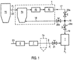
- Fig. 1 schematically shows a first embodiment of the present invention.
- the device comprises a supply line 22 via which, for example, from a mixing tank 15 via a pumping device, not shown, a second product flow P2 of the device can be supplied.
- the apparatus further comprises a device 4 for the thermal aseptic treatment of the second product stream P2.
- this device 4 is a KZE system (short-term heating), which in particular, as in Fig. 1 is represented, a feed tank 4a, a heat exchanger 4b (plate or tube) and a heat retaining plug 4c, for example in the form of coils, comprises.
- KZE system short-term heating
- a line section 17, 19 is provided, via which the second product stream P2 can be supplied to a filling valve 1.
- no further cooling device is provided, so that the product flow P2 can be supplied to the valve 1 hot.
- the line section 17, 19 there is a branch 16, from which leads away a bypass line 18, via which the second product stream P2 is at least partially and / or temporarily traceable to the device 4 for thermal treatment. This means that a freely adjustable overcurrent can be recirculated via the bypass line 18.
- this bypass line 18 and the fact that the second product flow P2 is supplied hot to the filling valve 1, is here no sterile buffer tank and no further cooling equipment necessary.
- the second product stream P2 is returned via the bypass line 18 to the buffer tank 4a.
- To set the respective volume flows are provided as an example corresponding control valves 20a, 20b, 20c, the z. B. in the lines 17, 19 and 20 are arranged.
- the device comprises a device 6 for the thermal aseptic treatment of a first product flow P1.
- This device 6 may for example also be a KZE system, which is constructed, for example, as explained in connection with Appendix 4.
- the hot product stream P1 is then cooled by means for cooling.
- This device can be formed from a heat exchanger 7 and / or a sterile buffer tank 7a.
- the section between the device 7, 7 a for cooling the first product stream P 1 is designed as a sterile line section 8.
- the line section as well as all components are to be carried out advantageously in accordance with the guidelines of the hygienic design. That In terms of design, the design must be space-minimized, surface-optimized and, for example, equipped with aseptic valves and control valves. In addition, it is advantageous that the line section can be sterilized.
- a control valve 21 may be located to adjust the volume flow.
- the product stream is generated via a pumping device, not shown.
- the first product stream P1 is fed to the filling valve 1 cold.
- the control valves 20c and 21 are provided here in the lines, but may also be integrated in the valve 1. It is essential that the ratio of the volume flows, which are mixed together, is adjustable.
- the second product stream P2 is added to the first product stream P1 hot.
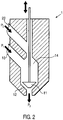
- the filling valve 1 comprises a mixing chamber 14, which has a z. B. upper inlet 23 for the second product flow P2 and a further inlet 10 for the first product flow P1, wherein in this area the two streams are merged.
- the hot product stream P2 With the cold product stream P1, the product stream P3 is filled at a mixing temperature during filling, with the product stream P3 then being able to enter the container.
- an upwardly and downwardly movable valve body 11 and a valve seat 12 are shown here.
- valve is not limited to this embodiment and, in particular, as in the German patent applications with the Anmeldeakten Kunststoff 102009032791.6 . 102009032794.0 . 102009032795.9 . 102009050388.9 described, be constructed.
- the first product is a substantially homogeneous liquid which is particularly transparent.
- the first product may be, for example, water, juice or even milk.
- the second product is z.
- As an inhomogeneous loaded with solids liquid such as in particular juice with pulp, juice with fibers, juice with cells or z.
- solids liquid such as in particular juice with pulp, juice with fibers, juice with cells or z.
- the viscosity of the first product is less than the viscosity of the second product.
- the first product may be cooled more easily than the second product could be cooled, so that it is favorable if the first product stream P1 is cooled and the second product stream P2 is not cooled.
- the first product is milk and, for example, cream as a second product.
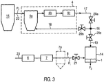
- Fig. 3 shows a further embodiment of the present invention, which corresponds to the in Fig. 1 shown embodiment, with the exception that here the second product stream P2 is the first product stream P1 before the filling valve 1 is mixed hot.
- the filling valve 1 does not include the mixing chamber 14, but a mixing chamber 14 is provided in the flow direction in front of the filling valve 1.
- an inline blender fulfills this task.
- the mixing chamber comprises an inlet for the first product stream P1 and an inlet for the second product stream P2, and an outlet via which the mixed product stream P3 can be supplied to the filling valve 1, which then feeds the product stream P3 to the container 3.
- the mixing chamber 14 can directly adjoin the valve 1, ie, the outlet of the mixing chamber is adjacent to the inlet of the valve. However, it may also be provided a line section between the mixing chamber 14 and the valve 1.
- the second product stream P2 is supplied for example from a mixing tank 15 via the line 22 of the device 4 for thermal aseptic treatment.
- the second product P2 is sterilized and leaves this device 4 with a temperature in a range of 72 to 98 ° C, here for example 90 ° C.
- the volume flow is, for example, in a range of 10 to 20% of the total flow P3, here in this embodiment 2 m 3 / h.
- the second product stream then passes via line 17 and 19 to the filling valve 1, with valves 20a, 20c open. When entering the filling valve 1, the product flow still has the aforementioned high temperature.
- An overflow, ie a part of the second product stream P2 can be recycled via the bypass line 18 of the device 4 for thermal aseptic treatment, ie here in the buffer tank 4a, to be reheated.
- the overcurrent, which is recycled in the bypass line 18, is about 1 to 5% of the volume flow of the second product stream P2 in the line 17th
- a first product stream of the device 6 for thermal aseptic treatment is supplied. Again, the product stream is heated and made sterile and leaves, for example, at a temperature of 72 to 140 ° C, the device 6. This hot first product stream P1 is then cooled to a temperature of 3 to 30 °, with which he the filling valve 1 on the Line section 8 is supplied.
- the first product stream P1 can be cooled via a heat exchanger 7 and / or stored in a sterile buffer tank 7a, in which the product cools or cools further.
- the control valve 21 When the control valve 21 is open, the first product stream can then be supplied to the valve 1 at a flow rate of 6 to 60 m 3 / h.
- the first product stream P1 for example, has a temperature of 15 ° C and a flow rate of 23 m 3 / h.
- the second product stream P2 By hot mixing the second product stream P2 with the first product stream P1, the second product stream can be cooled by the first product stream P1. This results in a mixed flow P3 with a mixing temperature. Since the volume flow of the first product stream P1 is greater than that of the second product stream P2, the hot product stream P2 can be cooled particularly quickly. Because the hot second product stream P2 can cool relatively quickly, for example, pieces of fruit pieces or thermally sensitive components can be filled particularly gently.
Landscapes
- Engineering & Computer Science (AREA)
- Mechanical Engineering (AREA)
- Filling Of Jars Or Cans And Processes For Cleaning And Sealing Jars (AREA)
- Basic Packing Technique (AREA)
- Confectionery (AREA)
- Food Preservation Except Freezing, Refrigeration, And Drying (AREA)
Description
- Die Erfindung betrifft ein Verfahren und eine Vorrichtung zum sterilen Abfüllen von zwei unterschiedlichen Produktströmen in einen Behälter gemäß den Oberbegriffen der Ansprüche 1 und 6.
- Beim Abfüllen von stückhaltigen Produkten, wie z. B. Säften mit Fruchtstückanteilen, werden zwei unterschiedliche Produktströme, z. B. ein erster Produktstrom aus Wasser oder Saft und ein zweiter Produktstrom, beispielsweise aus Saft mit Fruchtstückchen, in einen Behälter abgefüllt. Dabei gibt es grundsätzlich zwei Möglichkeiten zum sterilen Abfüllen. Beide Produktströme können thermisch behandelt werden und jeweils heiß zu einem Füller gefördert werden, wo die Produktströme getrennt in einen Behälter gefüllt werden. In diesem Fall braucht das abgefüllte Produkt relativ lange bis es abgekühlt ist, was aber das Produkt, z. B. die Fruchtstückchen, stark belastet.
- Es ist auch möglich die beiden Produktströme erst thermisch zu behandeln und abzukühlen bevor man sie zu den Füllern fördert. Man braucht aber dann vom Sterilisator bzw. Pasteur bis zum Füller eine sterile Strecke, damit das Produkt nicht wieder neu kontaminiert wird. Diese Lösung ist jedoch technisch aufwendig.
- Aus der
DE 10 2008 038 638 A1 ist bereits ein Verfahren und eine Vorrichtung gemäß den Oberbegriffen der Ansprüche 1 und 6 bekannt. Dabei wird ein Füllsystem verwendet mit wenigstens einem Füllelement zur gesteuerten Abgabe des Füllgutes, wobei ein zweiter heißer Produktstrom einem ersten kalten Produktstrom vor dem Abfüllventil heiß zugemischt wird. - Hiervon ausgehend liegt der vorliegenden Erfindung die Aufgabe zugrunde, ein Verfahren und eine Vorrichtung zum sterilen Abfüllen von zwei unterschiedlichen Produktströmen in einem Behälter bereitzustellen, die ein apparativ einfacheres und trotzdem produktschonenderes Abfüllen ermöglichen.
- Erfindungsgemäß wird diese Aufgabe durch die Merkmale der Ansprüche 1 und 6 gelöst.
- Gemäß der vorliegenden Erfindung wird nun also ein erster Produktstrom zur Pasteurisierung/Sterilisierung thermisch behandelt, abgekühlt und einem Abfüllventil zugeführt, während der zweite Produktstrom thermisch behandelt und dann dem ersten Produktstrom vor oder im Abfüllventil heiß zugemischt wird. "Vor dem Abfüllventil" bedeutet hier ohne Zwischenschalten einer Kühleinrichtung oder eines Puffertanks.
- Dies bringt den Vorteil mit sich, dass der zweite heiße Produktstrom durch den ersten Produktstrom gekühlt werden kann und für den zweiten Produktstrom keine separate Kühlsektion notwendig ist. Außerdem ist für den zweiten Produktstrom bis zur Abfüllung keine sterile Produktstrecke notwendig, da der zweite Produktstrom heiß zum Abfüllventil geführt wird. Somit ergibt sich eine kompakte und kostengünstige Anlage.
- Weiter ergibt sich der Vorteil, dass der zweite Produktstrom, der beispielsweise Fruchtstückchen etc. enthält, rasch durch den ersten Produktstrom abgekühlt werden kann, was besonders produktschonend ist.
- Es ist besonders vorteilhaft, wenn der zweite Produktstrom im Abfüllventil dem ersten Produktstrom heiß zugemischt wird, da dann der gesamte Produktweg des zweiten heißen Produktstroms bis ins Abfüllventil aufgrund der hohen Temperatur des zweiten Produktstroms ohne weitere Maßnahmen steril gehalten wird. Die Mischtemperatur stellt sich dann während des Füllens ein. Eine solche Anordnung ist apparativ besonders einfach.
- Vorteilhafterweise liegt die Temperatur des ersten Produktstroms beim Zusammenmischen in einen Bereich von 3 - 30 °C und die Temperatur des zweiten Produktstroms liegt in einem Temperaturbereich von 72 - 98°C. Das bedeutet, dass der zweite Produktstrom rasch abgekühlt werden kann.
- Besonders vorteilhaft ist es, wenn der Volumenstrom des ersten Produktstroms größer ist, als der des zweiten Produktstroms. Somit kann der zweite Produktstrom sehr rasch abgekühlt werden. Gemäß einer bevorzugten Ausführungsform wird der zweite Produktstrom nach der thermischen Behandlung, insbesondere nach einer Kurzzeiterhitzung oder Heißhaltung, direkt vor oder im Abfüllventil dem ersten Produktstrom P1 zugeführt. Somit kann die Anlage weiter vereinfacht werden.
- Gemäß der Erffindung wird der zweite Produktstrom zumindest teilweise und/oder zeitweise über eine Bypassleitung einer Einrichtung zur thermischen Behandlung des zweiten Produktstroms rückgeführt. Das heißt, dass ein Teil des zweiten Produktstroms nicht dem ersten Produktstrom zugemischt wird bzw. nicht zu dem Abfüllventil geleitet wird und, dass ein Überstrom, d.h. ein Überschuss des zweiten Produkts, der nicht durch das Abfüllventil abgefüllt wird, im Kreislauf zurück zu einer Einrichtung zur thermischen Behandlung des zweiten Produktstroms rückgeführt werden kann. Diese Bypassführung ermöglicht, dass auf einen Sterilpuffertank verzichtet werden kann.
- Vorteilhafterweise hat das erste Produkt eine niedrigere Viskosität als das zweite. Dadurch, dass das erste Produkt eine kleinere Viskosität als das zweite Produkt hat, und das erste Produkt und nicht das zweite Produkt gekühlt wird, kann eine Einrichtung zum Kühlen einfacher und kostengünstiger realisiert werden. In vorteilhafter Weise kann das erste Produkt eine im wesentlichen homogene Flüssigkeit, insbesondere Wasser, Saft oder Milch sein, während das zweite Produkt eine inhomogene mit Feststoffstückchen beladene Flüssigkeit, insbesondere Saft mit Pulpe, Saft mit Fasern oder Zellen, Sirup oder aber Rahm ist. Das heißt, dass beispielsweise jeweils folgende unterschiedliche Produktstrompaare in einen Behälter gefüllt werden können, Saft/Saft mit Pulpe, Saft/Saft mit Fasern oder Zellen, Wasser/Sirup, Milch/Rahm.
- Eine Vorrichtung zum sterilen Abfüllen von zwei unterschiedlichen Produktströmen in einem Behälter umfasst eine Einrichtung zur thermischen Behandlung eines ersten Produktstroms und eine Einrichtung zum Abkühlen des ersten Produktstroms. Die Einrichtung zum Abkühlen kann dabei beispielsweise in Form eines Wärmetauschers bevorzugter Weise eines Plattenwärmetauschers ausgebildet sein. In dem nachfolgenden Sterilpuffertank kann dann das bereits gekühlte Produkt zwischengelagert werden.
- Der zweite Produktstrom wird dem ersten Produktstrom in einer Mischkammer, d.h. einem Mischbereich zugemischt. Wie bereits erwähnt, ist es besonders vorteilhaft, wenn das Abfüllventil selbst diese Mischkammer aufweist. Es ist jedoch auch möglich, dass die Mischkammer in Produktstromrichtung vor dem Abfüllventil angeordnet ist, wobei dann dem Abfüllventil der zusammengemischte Produktstrom zugeführt wird. Vor dem Abfüllventil bedeutet, in einem Bereich bzw. Leitungsabschnitt zwischen einer Einrichtung zur thermischen Behandlung des zweiten Produktstroms und dem Abfüllventil, wobei in diesem Abschnitt keine Kühleinrichtung vorgesehen ist.
- Vorteilhafterweise ist die Einrichtung zur thermischen Behandlung des zweiten Produktstroms eine Sterilisation/Pasteurisationsanlage, die einen Vorlauftank, einen Wärmetauscher, bevorzugter Weise eines Röhrenwärmetauschers und eine Warmhaltestrecke, z. B. in Form von Rohrschlangen, aufweisen kann, wobei die Warmhaltestrecke direkt über eine Leitung mit der Mischkammer verbunden ist. Das bedeutet, dass kein Sterilpuffertank zwischen der Einrichtung zur thermischen Behandlung, d. h. insbesondere zwischen der Warmhaltestrecke und der Mischkammer bzw. dem Abfüllventil, vorgesehen ist.
- Erfindungsgemäß ist zwischen der Einrichtung zur thermischen Behandlung des zweiten Produktstroms und der Mischkammer bzw. dem Abfüllventil eine Bypassleitung vorgesehen, über die der zweite Produktstrom zumindest teilweise und/oder zeitweise zur Einrichtung zur thermischen Behandlung des Produktstroms, insbesondere zum Vorlauftank rückführbar ist. Somit kann ein Überstrom (1 bis 100 % vorteilhafterweise 5 % des gesamten zweiten Produktstroms vor dem Abzweigen des Bypassstroms) wirksam rückgeführt und erneut dem zweiten Produktstrom zur Erwärmung zugeführt werden.
- Der Leitungsabschnitt zwischen der Einrichtung zum Kühlen des ersten Produktstroms und dem Abfüllventil ist vorzugsweise als steriler Leitungsabschnitt ausgebildet. Somit kann sichergestellt werden, dass der kalte Produktstrom in diesem Bereich nicht verkeimt.
- Die Erfindung bringt den Vorteil mit sich, dass nur dieser kleine Leitungsabschnitt als steriler Leitungsabschnitt ausgebildet werden muss und das Produkt insgesamt dennoch nur mit minimal notwendiger thermischer Belastung abgefüllt werden kann.
- Der Volumenstrom in der Bypassleitung ist durch eine entsprechende Einrichtung einstellbar. Eine solche Einrichtung kann z. B. ein Stellventil in der Bypassleitung und/oder in der Leitung zur Mischkammer bzw. zum Abfüllventil sein und/oder in der Mischkammer bzw. dem Ventil integriert sein.
- Die Erfindung wird nachfolgend unter Bezugnahme folgender Figuren näher erläutert.
- Fig. 1
- zeigt schematisch den Aufbau einer Vorrichtung gemäß einer Ausführungsform der vorliegenden Erfindung.
- Fig. 2
- zeigt schematisch den Aufbau eines Abfüllventils gemäß der vorliegenden Erfindung.
- Fig. 3
- zeigt eine weitere Ausführungsform der vorliegenden Erfindung.
-
Fig. 1 zeigt schematisch eine erste Ausführungsform der vorliegenden Erfindung. Die Vorrichtung umfasst eine Zuleitung 22 über die beispielsweise von einem Ausmischtank 15 über eine nicht dargestellte Pumpeinrichtung ein zweiter Produktstrom P2 der Vorrichtung zugeführt werden kann. Die Vorrichtung umfasst weiter eine Einrichtung 4 zum thermischen aseptischen Behandeln des zweiten Produktstroms P2. Vorteilhafterweise ist diese Einrichtung 4 eine KZE-Anlage (Kurzzeiterhitzung), die insbesondere, wie inFig. 1 dargestellt ist, einen Vorlauftank 4a, einen Wärmetauscher 4b (Platte oder Röhre) sowie eine Wärmehaltestecke 4c, beispielsweise in Form von Rohrschlangen, umfasst. In Stromrichtung nach der Einrichtung zur thermischen aseptischen Behandlung des zweiten Produktstroms P2 ist ein Leitungsabschnitt 17, 19 vorgesehen, über den der zweite Produktstrom P2 einem Abfüllventil 1 zugeführt werden kann. In dem Leitungsabschnitt 17 und 19 ist keine weitere Kühleinrichtung vorgesehen, so dass der Produktstrom P2 dem Ventil 1 heiß zugeführt werden kann. In dem Leitungsabschnitt 17, 19 befindet sich eine Abzweigung 16, von der aus eine Bypassleitung 18 wegführt, über die der zweite Produktstrom P2 zumindest teilweise und/oder zeitweise zur Einrichtung 4 zur thermischen Behandlung rückführbar ist. Das heißt, dass ein frei einstellbarer Überstrom über die Bypassleitung 18 im Kreis rückgeführt werden kann. Durch diese Bypassleitung 18 sowie die Tatsache, dass der zweite Produktstrom P2 dem Abfüllventil 1 heiß zugeführt wird, ist hier kein Sterilpuffertank und keine weitere Kühleinrichtung notwendig. In diesem Ausführungsbeispiel wird der zweite Produktstrom P2 über die Bypassleitung 18 dem Puffertank 4a rückgeführt. Zum Einstellen der jeweiligen Volumenströme sind als Beispiel entsprechende Stellventile 20a, 20b, 20c vorgesehen, die z. B. in den Leitungen 17, 19 und 20 angeordnet sind. - Ferner umfasst die Vorrichtung eine Einrichtung 6 zur thermischen aseptischen Behandlung eines ersten Produktstroms P1. Diese Einrichtung 6 kann beispielsweise ebenfalls eine KZE-Anlage sein, die beispielsweise so aufgebaut ist wie im Zusammenhang mit der Anlage 4 erläutert wurde. Der heiße Produktstrom P1 wird dann über eine Einrichtung zum Abkühlen abgekühlt. Diese Einrichtung kann aus einem Wärmetauscher 7 und/oder einen sterilen Puffertank 7a gebildet sein. Der Abschnitt zwischen der Einrichtung 7, 7a zum Abkühlen des ersten Produktstroms P1 ist als steriler Leitungsabschnitt 8 ausgebildet. Um einen sterilen Leitungsabschnitt bereitzustellen werden beispielsweise folgende Maßnahmen getroffen. Der Leitungsabschnitt sowie alle Komponenten sind in vorteilhafter Weise gemäß der Richtlinien des hygienischen Designs auszuführen. D.h. konstruktiv muss die Ausführung totraumminimiert, oberflächenoptimiert sowie beispielsweise mit aseptisch ausgeführten Ventilen und Regelventilen ausgestattet sein. Außerdem ist es vorteilhaft, dass der Leitungsabschnitt sterilisierbar ist.
- In dem Leitungsabschnitt 8 kann sich zum Einstellen des Volumenstroms beispielsweise ein Stellventil 21 befinden. Der Produktstrom wird über eine nicht dargestellte Pumpeinrichtung erzeugt. Der erste Produktstrom P1 wird dem Abfüllventil 1 kalt zugeführt. Die Stellventile 20c und 21 sind hier in den Leitungen vorgesehen, können aber auch in dem Ventil 1 integriert sein. Wesentlich ist, dass das Verhältnis der Volumenströme, die zusammengemischt werden, einstellbar ist.
- In dem Abfüllventil 1 wird der zweite Produktstrom P2 dem ersten Produktstrom P1 heiß zugemischt. Dazu kann beispielsweise das in
Fig. 2 grob schematisch gezeigte Abfüllventil verwendet werden. Das Abfüllventil 1 umfasst eine Mischkammer 14, die einen z. B. oberen Zulauf 23 für den zweiten Produktstrom P2 und einen weiteren Zulauf 10 für den ersten Produktstrom P1 aufweist, wobei in diesem Bereich die beiden Ströme zusammengeführt werden. Durch das Zusammenführen des heißen Produktstroms P2 mit dem kalten Produktstrom P1 ergibt sich beim Füllen der Produktstrom P3 mit einer Mischtemperatur, wobei der Produktstrom P3 dann in den Behälter einlaufen kann. Nur grob schematisch sind hier ein auf- und ab beweglicher Ventilkörper 11 und ein Ventilsitz 12 dargestellt. Das Ventil ist selbstverständlich nicht auf diese Ausführungsform beschränkt und kann insbesondere, wie in den deutschen Patentanmeldungen mit den Anmeldeaktenzeichen102009032791.6 102009032794.0 102009032795.9 102009050388.9 - Das erste Produkt ist eine im Wesentlichen homogene Flüssigkeit, die insbesondere transparent ist. Das erste Produkt kann beispielsweise Wasser, Saft oder aber auch Milch sein. Das zweite Produkt ist z. B. eine inhomogene mit Feststoffen beladene Flüssigkeit, wie insbesondere Saft mit Pulpe, Saft mit Fasern, Saft mit Zellen oder z. B. Sirup. Die Viskosität des ersten Produkts ist kleiner als die Viskosität des zweiten Produkts. Demnach kann das erste Produkt einfacher gekühlt werden als das zweite Produkt gekühlt werden könnte, so dass es günstig ist, wenn der erste Produktstrom P1 gekühlt wird und der zweite Produktstrom P2 nicht gekühlt wird. Als erstes Produkt kommt jedoch auch Milch und als zweites Produkt beispielsweise Sahne in Frage.
-
Fig. 3 zeigt ein weiteres Ausführungsbeispiel der vorliegenden Erfindung, das dem inFig. 1 gezeigten Ausführungsbeispiel entspricht, mit der Ausnahme, dass hier der zweite Produktstrom P2 dem ersten Produktstrom P1 vor dem Abfüllventil 1 heiß zugemischt wird. Das bedeutet, dass hier das Abfüllventil 1 die Mischkammer 14 nicht umfasst, sondern eine Mischkammer 14 in Stromrichtung vor dem Abfüllventil 1 vorgesehen ist. Beispielsweise erfüllt ein Inline Blender diese Aufgabe. Die Mischkammer umfasst auch hier einen Zulauf für den ersten Produktstrom P1 sowie einen Zulauf für den zweiten Produktstrom P2, und einen Auslauf, über den der gemischte Produktstrom P3 dem Abfüllventil 1 zugeführt werden kann, welches dann den Produktstrom P3 dem Behälter 3 zuführt. Die Mischkammer 14 kann direkt an das Ventil 1 angrenzen, d. h., der Auslauf der Mischkammer grenzt an den Einlauf des Ventils. Es kann jedoch auch ein Leitungsabschnitt zwischen der Mischkammer 14 und dem Ventil 1 vorgesehen sein. - Es ist jedoch vorteilhaft, die Produktströme direkt in dem Ventil 1 zusammenzuführen, da eine entsprechende Anordnung einfacher ist und darüber hinaus sichergestellt ist, dass die Leitungsabschnitte 17 und 19 zwischen der Einrichtung 4 zur thermischen aseptischen Behandlung und dem Abfüllventil 1 auf möglichst hoher Temperatur gehalten werden können. Auch wird das Abfüllventil 1 durch den heißen Produktstrom P2 steril gehalten.
- Nachfolgend wird das erfindungsgemäße Verfahren im Zusammenhang mit der
Fig. 1 näher erläutert. - Der zweite Produktstrom P2 wird beispielsweise von einem Ausmischtank 15 über die Leitung 22 der Einrichtung 4 zur thermischen aseptischen Behandlung zugeführt. In dieser Einrichtung 4 wird das zweite Produkt P2 sterilisiert und verlässt diese Einrichtung 4 mit einer Temperatur in einem Bereich von 72 bis 98 °C, hier beispielsweise 90 °C. Der Volumenstrom liegt beispielsweise in einem Bereich von 10 - 20% vom Gesamtstrom P3, hier bei diesem Ausführungsbeispiel 2 m3/h. Der zweite Produktstrom läuft dann über die Leitung 17 und 19 zu dem Abfüllventil 1, bei geöffneten Ventilen 20a, 20c. Beim Eintritt in das Abfüllventil 1 weist der Produktstrom immer noch die zuvor genannte hohe Temperatur auf. Ein Überstrom, d. h. ein Teil des zweiten Produktstroms P2, kann über die Bypassleitung 18 der Einrichtung 4 zur thermischen aseptischen Behandlung rückgeführt werden, d. h. hier in dem Puffertank 4a, um erneut erwärmt zu werden. Der Überstrom, der in der Bypassleitung 18 rückgeführt wird, beträgt etwa 1 bis 5 % des Volumenstroms des zweiten Produktstroms P2 in der Leitung 17.
- Über die Leitung 23 wird ein erster Produktstrom der Einrichtung 6 zur thermischen aseptischen Behandlung zugeführt. Auch hier wird der Produktstrom erhitzt und steril gemacht und verlässt beispielsweise mit einer Temperatur von 72 bis 140 °C die Einrichtung 6. Dieser heiße erste Produktstrom P1 wird dann auf eine Temperatur von 3 bis 30° abgekühlt, mit der er dem Abfüllventil 1 über den Leitungsabschnitt 8 zugeführt wird. Der erste Produktstrom P1 kann über einen Wärmetauscher 7 abgekühlt und/oder in einen sterilen Puffertank 7a eingelagert werden, in dem das Produkt abkühlt oder weiter abkühlt. Bei geöffnetem Stellventil 21 kann der erste Produktstrom dann mit einem Volumenstrom von 6 bis 60 m3/h dem Ventil 1 zugeführt werden. Hier hat der erste Produktstrom P1 beispielsweise eine Temperatur von 15 °C und einen Volumenstrom von 23 m3/h.
- Indem der zweite Produktstrom P2 dem ersten Produktstrom P1 heiß zugemischt wird, kann der zweite Produktstrom durch den ersten Produktstrom P1 abgekühlt werden. Es ergibt sich ein Mischstrom P3 mit einer Mischtemperatur. Da der Volumenstrom des ersten Produktstroms P1 größer als der des zweiten Produktstroms P2 ist, kann der heiße Produktstrom P2 besonders schnell gekühlt werden. Dadurch, dass der heiße zweite Produktstrom P2 relativ schnell abkühlen kann, können beispielsweise Fruchtstückanteile oder thermisch empfindliche Bestandteile besonders schonend abgefüllt werden.
- Das Verfahren wurde im Zusammenhang mit dem ersten Ausführungsbeispiel erläutert. Das erfindungsgemäße Verfahren funktioniert auf gleicher Weise mit dem zweiten in
Fig. 3 gezeigten Ausführungsbeispiel, nur dass hier die Produktströme in einer Mischkammer 14 zusammengefügt werden, die sich in Strömungsrichtung vor dem Abfüllventil 1 befindet.
Claims (10)
- Verfahren zum sterilen Abfüllen von zwei unterschiedlichen Produktströmen (P1, P2) in einen Behälter, wobei
der erste Produktstrom (P1) zum Pasteurisieren/Sterilisieren thermisch behandelt, abgekühlt und einem Abfüllventil (1) zugeführt wird, und
der zweite Produktstrom (P2) zum Pasteurisieren/Sterilisieren thermisch behandelt und dann dem ersten Produktstrom (P1) vor oder im Abfüllventil (1) heiß zugemischt wird, dadurch gekennzeichnet, dass
der zweite Produktstrom (P2) zumindest teilweise und/oder zeitweise über eine Bypassleitung (18) einer Einrichtung zur thermischen Behandlung des zweiten Produktstroms (P2) rückgeführt wird. - Verfahren nach Anspruch 1, dadurch gekennzeichnet, dass beim Zusammenmischen die Temperatur des ersten Produktstroms (P1) in einem Bereich von 3 - 30°C und die Temperatur des zweiten Produktstroms (P2) in einem Temperaturbereich von 72 bis 98 °C liegt.
- Verfahren nach Anspruch 1 oder 2, dadurch gekennzeichnet, dass beim Zusammenmischen der Volumenstrom des ersten Produktstroms (P1) größer als der des zweiten Produktstroms (P2) ist.
- Verfahren nach mindestens einem der Ansprüche 1 bis 3, dadurch gekennzeichnet, dass der zweite Produktstrom (P2) nach einer Kurzzeiterhitzung und Heißhaltung direkt vor oder im Abfüllventil (1) dem ersten Produktstrom (P1) zugemischt wird.
- Verfahren nach mindestens einem der Ansprüche 1 bis 4, dadurch gekennzeichnet, dass das erste Produkt eine niedrigere Viskosität aufweist als das zweite Produkt und das erste Produkt vorzugsweise eine im wesentlichen homogene Flüssigkeit, insbesondere Wasser, Saft oder Milch, ist und das zweite Produkt eine inhomogene Flüssigkeit mit Feststoffstückchen, insbesondere Saft mit Pulpe, mit Fasern oder mit Zellen, Sirup oder aber Rahm ist.
- Vorrichtung zum sterilen Abfüllen von zwei unterschiedlichen Produktströmen (P1, P2) in einen Behälter mit
einer Einrichtung (6) zum thermischen aseptischen Behandeln eines ersten Produktstroms (P1),
einer Einrichtung (7;7a) zum Abkühlen des ersten Produktstroms (P1),
einer Einrichtung (4) zum thermischen aseptischen Behandeln eines zweiten Produktstroms (P2),
einem Abfüllventil (1), das eine Mischkammer (14) aufweist oder mit einer Mischkammer (14) verbunden ist, wobei die Mischkammer (14) derart angeordnet ist, dass der heiße zweite Produktstrom (P2) dem ersten abgekühlten Produktstrom (P1) zugemischt werden kann und der zusammengemischte Produktstrom (P3) dem Behälter zugeführt werden kann, dadurch gekennzeichnet,
dass von einer Leitung (17, 19) zwischen der Einrichtung (4) zur thermischen Behandlung des zweiten Produktstroms (4) und der Mischkammer (14) bzw. dem Abfüllventil (1) eine Bypassleitung (18) vorgesehen ist, über die der zweite Produktstrom (P2) zumindest teilweise und/oder zeitweise zur Einrichtung zur thermischen Behandlung des zweiten Produktstroms (4) rückführbar ist. - Vorrichtung nach Anspruch 6, dadurch gekennzeichnet, dass die Einrichtung zur thermischen Behandlung (4) des zweiten Produktstroms eine Pasteurisations/Sterilisationsanlage ist, die einen Vorlauftank (4a), einen Wärmetauscher (4b) und eine Warmhaltestrecke (4c) umfasst, wobei die Warmhaltestrecke (4c) direkt über eine Leitung (17, 19) mit der Mischkammer (14) verbunden ist.
- Vorrichtung nach mindestens Anspruch 6 und 7, dadurch gekennzeichnet, dass die Bypassleitung (18) in den Vorlauftank (4a) mündet.
- Vorrichtung nach mindestens einem der Ansprüche 6 bis 8, dadurch gekennzeichnet, dass ein Leitungsabschnitt (8) zwischen der Einrichtung (7) zum Kühlen des ersten Produktstroms und dem Abfüllventil (1) als steriler Leitungsabschnitt (8) ausgebildet ist.
- Vorrichtung nach mindestens Anspruch 6, dadurch gekennzeichnet, dass die Vorrichtung eine Einrichtung (20b;20c) zum Einstellen des Volumenstroms in der Bypassleitung (18) umfasst.
Applications Claiming Priority (1)
| Application Number | Priority Date | Filing Date | Title |
|---|---|---|---|
| DE201010002407 DE102010002407A1 (de) | 2010-02-26 | 2010-02-26 | Verfahren und Vorrichtung zum sterilen Abfüllen von zwei unterschiedlichen Produktströmen in einen Behälter |
Publications (3)
| Publication Number | Publication Date |
|---|---|
| EP2361873A2 EP2361873A2 (de) | 2011-08-31 |
| EP2361873A3 EP2361873A3 (de) | 2015-05-27 |
| EP2361873B1 true EP2361873B1 (de) | 2017-08-16 |
Family
ID=43903870
Family Applications (1)
| Application Number | Title | Priority Date | Filing Date |
|---|---|---|---|
| EP11150972.5A Not-in-force EP2361873B1 (de) | 2010-02-26 | 2011-01-14 | Verfahren und Vorrichtung zum sterilen Abfüllen von zwei unterschiedlichen Produktströmen in einen Behälter |
Country Status (5)
| Country | Link |
|---|---|
| US (1) | US20110209796A1 (de) |
| EP (1) | EP2361873B1 (de) |
| CN (1) | CN102190100A (de) |
| BR (1) | BRPI1100345A2 (de) |
| DE (1) | DE102010002407A1 (de) |
Families Citing this family (21)
| Publication number | Priority date | Publication date | Assignee | Title |
|---|---|---|---|---|
| US20140377418A1 (en) * | 2013-06-21 | 2014-12-25 | Noble House, LLC | Method and Apparatus for Hub and Spoke Aseptic Processing |
| US20170127704A1 (en) * | 2014-06-10 | 2017-05-11 | Tetra Laval Holdings & Finance S.A. | System and method for processing liquid or semi-liquid food products |
| DE102014108416A1 (de) * | 2014-06-16 | 2015-12-17 | Krones Ag | Verfahren und Vorrichtung zum Befüllen eines Behälters mit einem Füllprodukt |
| DE102016116529A1 (de) * | 2016-09-05 | 2018-03-08 | Sig Technology Ag | Füllmaschine und Verfahren zum sterilen Abfüllen eines Lebensmittels umfassend eine Hauptkomponente und eine Zusatzkomponente |
| DE102016217342A1 (de) * | 2016-09-12 | 2018-03-15 | Krones Ag | Abfüllanlage zum Wärmebehandeln und Abfüllen einer Flüssigkeit |
| CN106395713B (zh) * | 2016-11-17 | 2019-02-05 | 广州达意隆包装机械股份有限公司 | 一种液体灌装机 |
| DE102017104313A1 (de) | 2017-03-01 | 2018-09-06 | Krones Ag | Vorrichtung zum Befüllen eines Behälters mit einem sterilisierten Füllprodukt |
| DE102017120322A1 (de) * | 2017-09-04 | 2019-03-07 | Krones Ag | Vorrichtung und Verfahren zum Befüllen eines Behälters mit einem Füllprodukt |
| DE102017120323A1 (de) * | 2017-09-04 | 2019-03-07 | Krones Ag | Vorrichtung zum Befüllen eines Behälters mit einem Füllprodukt |
| CN108569425A (zh) * | 2017-12-29 | 2018-09-25 | 广州美中生物科技有限公司 | 一种无添加防腐剂含活性物质的液体的灌装机 |
| CN108408097B (zh) * | 2018-03-14 | 2020-11-13 | 山东碧海包装材料有限公司 | 一种带颗粒液体灌装方法 |
| CN112188933B (zh) | 2018-06-21 | 2022-08-16 | 宝洁公司 | 用于共注入两种或更多种液体的一体式分配喷嘴及其使用方法 |
| JP6897716B2 (ja) * | 2019-06-14 | 2021-07-07 | 大日本印刷株式会社 | 無菌充填機の充填バルブの冷却方法 |
| DE102019118091A1 (de) * | 2019-07-04 | 2021-01-07 | Krones Ag | Verfahren und Vorrichtung zum Befüllen eines zu befüllenden Behälters mit einem karbonisierten Füllprodukt |
| DE102019133122A1 (de) * | 2019-12-05 | 2021-06-10 | Krones Ag | Vorrichtung zur Herstellung und Bereitstellung von Sterilwasser und Verfahren zum Betreiben der Vorrichtung |
| CA3156424C (en) | 2019-12-16 | 2024-07-02 | The Procter & Gamble Company | LIQUID DISTRIBUTION SYSTEM INCLUDING A UNIT DISTRIBUTION NOZZLE |
| DE102020131579A1 (de) * | 2020-11-27 | 2022-06-02 | Krones Aktiengesellschaft | Vorrichtung und Verfahren zum Befüllen eines Behälters mit einem Füllprodukt |
| CN114750991B (zh) * | 2022-04-22 | 2023-08-01 | 杭州娃哈哈精密机械有限公司 | 一种全自动多种果肉添加装置 |
| WO2024017323A1 (zh) * | 2022-07-20 | 2024-01-25 | 浙江健新原力制药有限公司 | 一种载体液无菌分装系统及其应用 |
| US12552657B2 (en) * | 2023-07-31 | 2026-02-17 | Vessl, Inc. | Sterile filling method for additive product containers |
| CN118419348A (zh) * | 2024-06-04 | 2024-08-02 | 江苏中饮机械有限公司 | 一种带有防溅料入水口的无菌灌装阀 |
Family Cites Families (14)
| Publication number | Priority date | Publication date | Assignee | Title |
|---|---|---|---|---|
| DE4008845A1 (de) * | 1990-03-20 | 1991-09-26 | Granini Gmbh | Verfahren zum aufbereiten von aus fruchtsaftkonzentrat o.dgl. hergestellten getraenken |
| US5361683A (en) * | 1992-05-04 | 1994-11-08 | Imdec Sa | Apparatus for batch cooking and packing fruit and vegetable pieces |
| ES2082319T3 (es) * | 1992-10-14 | 1996-03-16 | Barilla Flli G & R | Un metodo para producir articulos alimenticios listos para el consumo y que tienen una prolongada vida en el almacenamiento. |
| US6045007A (en) * | 1998-08-10 | 2000-04-04 | Lancer Partnership, Ltd. | Beverage dispenser configuration |
| US6405764B1 (en) * | 2001-02-21 | 2002-06-18 | The Coca-Cola Company | System and method for packaging of beverages in containers at controlled temperatures |
| US6599546B2 (en) * | 2001-05-18 | 2003-07-29 | The Coca Cola Company | Process and apparatus for in-line production of heat-processed beverage made from concentrate |
| CN2850709Y (zh) * | 2005-11-07 | 2006-12-27 | 韩毅军 | 热熔胶打胶机 |
| CN101077764A (zh) * | 2006-05-08 | 2007-11-28 | 桂格燕麦公司 | 具有调味剂注入的热灌装饮料生产 |
| DE102006045987A1 (de) * | 2006-09-27 | 2008-04-03 | Khs Ag | Verfahren zum Füllen von Behältern mit einem flüssigen Füllgut sowie Füllsystem |
| DE102008038638A1 (de) * | 2008-08-12 | 2010-02-25 | Khs Ag | Verfahren zum Abfüllen eines aus wenigstens einer ersten und einer zweiten Komponente bestehenden Füllgutes |
| DE102009032794A1 (de) | 2009-07-10 | 2011-01-13 | Krones Ag | Vorrichtung zum Befüllen von Behältnissen mit mehrkomponentigen Flüssigkeiten |
| DE102009032795A1 (de) | 2009-07-10 | 2011-01-13 | Krones Ag | Einfülleinrichtung zum Befüllen von Behältnissen |
| DE102009032791A1 (de) | 2009-07-10 | 2011-01-13 | Krones Ag | Vorrichtung zum Abfüllen mehrkomponentiger Getränke |
| DE102009050388A1 (de) | 2009-10-22 | 2011-04-28 | Krones Ag | Vorrichtung und Verfahren zum verlustfreien Abfüllen von kontinuierlich gemischten Medien in Behältnisse |
-
2010
- 2010-02-26 DE DE201010002407 patent/DE102010002407A1/de not_active Withdrawn
-
2011
- 2011-01-14 EP EP11150972.5A patent/EP2361873B1/de not_active Not-in-force
- 2011-02-25 US US13/034,779 patent/US20110209796A1/en not_active Abandoned
- 2011-02-25 BR BRPI1100345 patent/BRPI1100345A2/pt not_active Application Discontinuation
- 2011-02-25 CN CN2011100471415A patent/CN102190100A/zh active Pending
Non-Patent Citations (1)
| Title |
|---|
| None * |
Also Published As
| Publication number | Publication date |
|---|---|
| EP2361873A3 (de) | 2015-05-27 |
| BRPI1100345A2 (de) | 2012-11-13 |
| EP2361873A2 (de) | 2011-08-31 |
| CN102190100A (zh) | 2011-09-21 |
| DE102010002407A1 (de) | 2011-09-01 |
| US20110209796A1 (en) | 2011-09-01 |
Similar Documents
| Publication | Publication Date | Title |
|---|---|---|
| EP2361873A2 (de) | Verfahren und Vorrichtung zum sterilen Abfüllen von zwei unterschiedlichen Produktströmen in einen Behälter | |
| WO2010017888A1 (de) | Verfahren zum abfüllen eines aus wenigstens einer ersten und einer zweiten komponente bestehenden füllgutes | |
| EP3509980B1 (de) | Abfüllanlage zum wärmebehandeln und abfüllen einer flüssigkeit | |
| DE69208086T2 (de) | Apparat und verfahren zum aseptischen herstellen von getränken | |
| DE3408517C2 (de) | Sterilisationsvorrichtung | |
| EP2388064A1 (de) | Vorrichtung und Verfahren zum Ausmischen von Getränken | |
| DE60038287T2 (de) | Verfahren zur regelung eines dampfinjektors | |
| EP2409582B1 (de) | Vorrichtung und Verfahren zum Ausmischen und Wärmebehandeln eines flüssigen Produkts | |
| EP3678982B1 (de) | Vorrichtung und verfahren zum befüllen eines behälters mit einem füllprodukt | |
| EP2299853B1 (de) | Pasteurisierungsanlage | |
| DE10034513A1 (de) | Desinfektion des gesamten Zirkulations-Volumenstromes | |
| EP3831456B1 (de) | Vorrichtung zur herstellung und bereitstellung von sterilwasser und verfahren zum betreiben der vorrichtung | |
| EP1610618B1 (de) | Vorrichtung zum bereitstellen von flüssigen lebensmitteln | |
| EP0166127A1 (de) | Verfahren zur Rückverdünnung von Frucht- und Gemüsesaftkonzentraten | |
| EP0036124A2 (de) | Vorrichtung für eine die Haltbarkeit erhöhende Wärmebehandlung, insbesondere Ultrahocherhitzung, von Keime enthaltenden Produkten | |
| DE10328518A1 (de) | Vorrichtung zum Bereitstellen von flüssigen Lebensmitteln | |
| DE19534855C1 (de) | Vorrichtung zum Erhitzen von Milch | |
| EP3166420B1 (de) | Wärmebehandlungsvorrichtung sowie verfahren zur wärmebehandlung | |
| DE202017101351U1 (de) | Einrichtung zum Erzeugen von Dampf | |
| EP1613167B1 (de) | Vorrichtung zum bereitstellen von flüssigem nahrungsmittel für tiere | |
| DE69312368T2 (de) | Verfahren und Vorrichtung zur Reinigung einer Wärmebehandlungsanlage für flüssige Produkte | |
| DE102018102512A1 (de) | Einrichtung zum Erzeugen von Dampf | |
| DE102020207908A1 (de) | Vorrichtung zur PEF-Behandlung von flüssigen Medien und Verfahren | |
| DE202014105946U1 (de) | Vorrichtung zum Befüllen von Behältern mit einem Füllprodukt | |
| DE102019202549A1 (de) | Vorrichtung und Verfahren zum Bereitstellen eines sterilisierten oder pasteurisierten flüssigen Lebensmittels |
Legal Events
| Date | Code | Title | Description |
|---|---|---|---|
| PUAI | Public reference made under article 153(3) epc to a published international application that has entered the european phase |
Free format text: ORIGINAL CODE: 0009012 |
|
| AK | Designated contracting states |
Kind code of ref document: A2 Designated state(s): AL AT BE BG CH CY CZ DE DK EE ES FI FR GB GR HR HU IE IS IT LI LT LU LV MC MK MT NL NO PL PT RO RS SE SI SK SM TR |
|
| AX | Request for extension of the european patent |
Extension state: BA ME |
|
| RIN1 | Information on inventor provided before grant (corrected) |
Inventor name: FEILNER, ROLAND |
|
| PUAL | Search report despatched |
Free format text: ORIGINAL CODE: 0009013 |
|
| AK | Designated contracting states |
Kind code of ref document: A3 Designated state(s): AL AT BE BG CH CY CZ DE DK EE ES FI FR GB GR HR HU IE IS IT LI LT LU LV MC MK MT NL NO PL PT RO RS SE SI SK SM TR |
|
| AX | Request for extension of the european patent |
Extension state: BA ME |
|
| RIC1 | Information provided on ipc code assigned before grant |
Ipc: B67C 3/26 20060101AFI20150422BHEP Ipc: B67C 3/02 20060101ALI20150422BHEP Ipc: B65B 55/14 20060101ALI20150422BHEP |
|
| 17P | Request for examination filed |
Effective date: 20150716 |
|
| RBV | Designated contracting states (corrected) |
Designated state(s): AL AT BE BG CH CY CZ DE DK EE ES FI FR GB GR HR HU IE IS IT LI LT LU LV MC MK MT NL NO PL PT RO RS SE SI SK SM TR |
|
| GRAP | Despatch of communication of intention to grant a patent |
Free format text: ORIGINAL CODE: EPIDOSNIGR1 |
|
| INTG | Intention to grant announced |
Effective date: 20170105 |
|
| GRAJ | Information related to disapproval of communication of intention to grant by the applicant or resumption of examination proceedings by the epo deleted |
Free format text: ORIGINAL CODE: EPIDOSDIGR1 |
|
| GRAP | Despatch of communication of intention to grant a patent |
Free format text: ORIGINAL CODE: EPIDOSNIGR1 |
|
| INTC | Intention to grant announced (deleted) | ||
| INTG | Intention to grant announced |
Effective date: 20170426 |
|
| RIN1 | Information on inventor provided before grant (corrected) |
Inventor name: FEILNER, ROLAND |
|
| GRAS | Grant fee paid |
Free format text: ORIGINAL CODE: EPIDOSNIGR3 |
|
| GRAA | (expected) grant |
Free format text: ORIGINAL CODE: 0009210 |
|
| AK | Designated contracting states |
Kind code of ref document: B1 Designated state(s): AL AT BE BG CH CY CZ DE DK EE ES FI FR GB GR HR HU IE IS IT LI LT LU LV MC MK MT NL NO PL PT RO RS SE SI SK SM TR |
|
| REG | Reference to a national code |
Ref country code: GB Ref legal event code: FG4D Free format text: NOT ENGLISH |
|
| REG | Reference to a national code |
Ref country code: CH Ref legal event code: EP |
|
| REG | Reference to a national code |
Ref country code: IE Ref legal event code: FG4D Free format text: LANGUAGE OF EP DOCUMENT: GERMAN |
|
| REG | Reference to a national code |
Ref country code: AT Ref legal event code: REF Ref document number: 918841 Country of ref document: AT Kind code of ref document: T Effective date: 20170915 |
|
| REG | Reference to a national code |
Ref country code: DE Ref legal event code: R096 Ref document number: 502011012786 Country of ref document: DE |
|
| REG | Reference to a national code |
Ref country code: SE Ref legal event code: TRGR |
|
| REG | Reference to a national code |
Ref country code: NL Ref legal event code: MP Effective date: 20170816 |
|
| REG | Reference to a national code |
Ref country code: LT Ref legal event code: MG4D |
|
| PG25 | Lapsed in a contracting state [announced via postgrant information from national office to epo] |
Ref country code: FI Free format text: LAPSE BECAUSE OF FAILURE TO SUBMIT A TRANSLATION OF THE DESCRIPTION OR TO PAY THE FEE WITHIN THE PRESCRIBED TIME-LIMIT Effective date: 20170816 Ref country code: LT Free format text: LAPSE BECAUSE OF FAILURE TO SUBMIT A TRANSLATION OF THE DESCRIPTION OR TO PAY THE FEE WITHIN THE PRESCRIBED TIME-LIMIT Effective date: 20170816 Ref country code: NO Free format text: LAPSE BECAUSE OF FAILURE TO SUBMIT A TRANSLATION OF THE DESCRIPTION OR TO PAY THE FEE WITHIN THE PRESCRIBED TIME-LIMIT Effective date: 20171116 Ref country code: NL Free format text: LAPSE BECAUSE OF FAILURE TO SUBMIT A TRANSLATION OF THE DESCRIPTION OR TO PAY THE FEE WITHIN THE PRESCRIBED TIME-LIMIT Effective date: 20170816 |
|
| PG25 | Lapsed in a contracting state [announced via postgrant information from national office to epo] |
Ref country code: LV Free format text: LAPSE BECAUSE OF FAILURE TO SUBMIT A TRANSLATION OF THE DESCRIPTION OR TO PAY THE FEE WITHIN THE PRESCRIBED TIME-LIMIT Effective date: 20170816 Ref country code: GR Free format text: LAPSE BECAUSE OF FAILURE TO SUBMIT A TRANSLATION OF THE DESCRIPTION OR TO PAY THE FEE WITHIN THE PRESCRIBED TIME-LIMIT Effective date: 20171117 Ref country code: PL Free format text: LAPSE BECAUSE OF FAILURE TO SUBMIT A TRANSLATION OF THE DESCRIPTION OR TO PAY THE FEE WITHIN THE PRESCRIBED TIME-LIMIT Effective date: 20170816 Ref country code: RS Free format text: LAPSE BECAUSE OF FAILURE TO SUBMIT A TRANSLATION OF THE DESCRIPTION OR TO PAY THE FEE WITHIN THE PRESCRIBED TIME-LIMIT Effective date: 20170816 Ref country code: IS Free format text: LAPSE BECAUSE OF FAILURE TO SUBMIT A TRANSLATION OF THE DESCRIPTION OR TO PAY THE FEE WITHIN THE PRESCRIBED TIME-LIMIT Effective date: 20171216 Ref country code: BG Free format text: LAPSE BECAUSE OF FAILURE TO SUBMIT A TRANSLATION OF THE DESCRIPTION OR TO PAY THE FEE WITHIN THE PRESCRIBED TIME-LIMIT Effective date: 20171116 Ref country code: ES Free format text: LAPSE BECAUSE OF FAILURE TO SUBMIT A TRANSLATION OF THE DESCRIPTION OR TO PAY THE FEE WITHIN THE PRESCRIBED TIME-LIMIT Effective date: 20170816 |
|
| PG25 | Lapsed in a contracting state [announced via postgrant information from national office to epo] |
Ref country code: CZ Free format text: LAPSE BECAUSE OF FAILURE TO SUBMIT A TRANSLATION OF THE DESCRIPTION OR TO PAY THE FEE WITHIN THE PRESCRIBED TIME-LIMIT Effective date: 20170816 Ref country code: RO Free format text: LAPSE BECAUSE OF FAILURE TO SUBMIT A TRANSLATION OF THE DESCRIPTION OR TO PAY THE FEE WITHIN THE PRESCRIBED TIME-LIMIT Effective date: 20170816 Ref country code: DK Free format text: LAPSE BECAUSE OF FAILURE TO SUBMIT A TRANSLATION OF THE DESCRIPTION OR TO PAY THE FEE WITHIN THE PRESCRIBED TIME-LIMIT Effective date: 20170816 |
|
| REG | Reference to a national code |
Ref country code: DE Ref legal event code: R097 Ref document number: 502011012786 Country of ref document: DE |
|
| PG25 | Lapsed in a contracting state [announced via postgrant information from national office to epo] |
Ref country code: SK Free format text: LAPSE BECAUSE OF FAILURE TO SUBMIT A TRANSLATION OF THE DESCRIPTION OR TO PAY THE FEE WITHIN THE PRESCRIBED TIME-LIMIT Effective date: 20170816 Ref country code: IT Free format text: LAPSE BECAUSE OF FAILURE TO SUBMIT A TRANSLATION OF THE DESCRIPTION OR TO PAY THE FEE WITHIN THE PRESCRIBED TIME-LIMIT Effective date: 20170816 Ref country code: EE Free format text: LAPSE BECAUSE OF FAILURE TO SUBMIT A TRANSLATION OF THE DESCRIPTION OR TO PAY THE FEE WITHIN THE PRESCRIBED TIME-LIMIT Effective date: 20170816 Ref country code: SM Free format text: LAPSE BECAUSE OF FAILURE TO SUBMIT A TRANSLATION OF THE DESCRIPTION OR TO PAY THE FEE WITHIN THE PRESCRIBED TIME-LIMIT Effective date: 20170816 |
|
| PLBE | No opposition filed within time limit |
Free format text: ORIGINAL CODE: 0009261 |
|
| STAA | Information on the status of an ep patent application or granted ep patent |
Free format text: STATUS: NO OPPOSITION FILED WITHIN TIME LIMIT |
|
| 26N | No opposition filed |
Effective date: 20180517 |
|
| PG25 | Lapsed in a contracting state [announced via postgrant information from national office to epo] |
Ref country code: SI Free format text: LAPSE BECAUSE OF FAILURE TO SUBMIT A TRANSLATION OF THE DESCRIPTION OR TO PAY THE FEE WITHIN THE PRESCRIBED TIME-LIMIT Effective date: 20170816 |
|
| REG | Reference to a national code |
Ref country code: CH Ref legal event code: PL |
|
| GBPC | Gb: european patent ceased through non-payment of renewal fee |
Effective date: 20180114 |
|
| PG25 | Lapsed in a contracting state [announced via postgrant information from national office to epo] |
Ref country code: MT Free format text: LAPSE BECAUSE OF FAILURE TO SUBMIT A TRANSLATION OF THE DESCRIPTION OR TO PAY THE FEE WITHIN THE PRESCRIBED TIME-LIMIT Effective date: 20170816 |
|
| PG25 | Lapsed in a contracting state [announced via postgrant information from national office to epo] |
Ref country code: LU Free format text: LAPSE BECAUSE OF NON-PAYMENT OF DUE FEES Effective date: 20180114 Ref country code: FR Free format text: LAPSE BECAUSE OF NON-PAYMENT OF DUE FEES Effective date: 20180131 |
|
| REG | Reference to a national code |
Ref country code: IE Ref legal event code: MM4A |
|
| REG | Reference to a national code |
Ref country code: FR Ref legal event code: ST Effective date: 20180928 |
|
| REG | Reference to a national code |
Ref country code: BE Ref legal event code: MM Effective date: 20180131 |
|
| PG25 | Lapsed in a contracting state [announced via postgrant information from national office to epo] |
Ref country code: GB Free format text: LAPSE BECAUSE OF NON-PAYMENT OF DUE FEES Effective date: 20180114 Ref country code: BE Free format text: LAPSE BECAUSE OF NON-PAYMENT OF DUE FEES Effective date: 20180131 Ref country code: CH Free format text: LAPSE BECAUSE OF NON-PAYMENT OF DUE FEES Effective date: 20180131 Ref country code: LI Free format text: LAPSE BECAUSE OF NON-PAYMENT OF DUE FEES Effective date: 20180131 |
|
| PG25 | Lapsed in a contracting state [announced via postgrant information from national office to epo] |
Ref country code: IE Free format text: LAPSE BECAUSE OF NON-PAYMENT OF DUE FEES Effective date: 20180114 |
|
| REG | Reference to a national code |
Ref country code: AT Ref legal event code: MM01 Ref document number: 918841 Country of ref document: AT Kind code of ref document: T Effective date: 20180114 |
|
| PG25 | Lapsed in a contracting state [announced via postgrant information from national office to epo] |
Ref country code: AT Free format text: LAPSE BECAUSE OF NON-PAYMENT OF DUE FEES Effective date: 20180114 |
|
| PG25 | Lapsed in a contracting state [announced via postgrant information from national office to epo] |
Ref country code: MC Free format text: LAPSE BECAUSE OF FAILURE TO SUBMIT A TRANSLATION OF THE DESCRIPTION OR TO PAY THE FEE WITHIN THE PRESCRIBED TIME-LIMIT Effective date: 20170816 |
|
| PG25 | Lapsed in a contracting state [announced via postgrant information from national office to epo] |
Ref country code: TR Free format text: LAPSE BECAUSE OF FAILURE TO SUBMIT A TRANSLATION OF THE DESCRIPTION OR TO PAY THE FEE WITHIN THE PRESCRIBED TIME-LIMIT Effective date: 20170816 |
|
| PG25 | Lapsed in a contracting state [announced via postgrant information from national office to epo] |
Ref country code: HU Free format text: LAPSE BECAUSE OF FAILURE TO SUBMIT A TRANSLATION OF THE DESCRIPTION OR TO PAY THE FEE WITHIN THE PRESCRIBED TIME-LIMIT; INVALID AB INITIO Effective date: 20110114 Ref country code: PT Free format text: LAPSE BECAUSE OF FAILURE TO SUBMIT A TRANSLATION OF THE DESCRIPTION OR TO PAY THE FEE WITHIN THE PRESCRIBED TIME-LIMIT Effective date: 20170816 |
|
| PG25 | Lapsed in a contracting state [announced via postgrant information from national office to epo] |
Ref country code: HR Free format text: LAPSE BECAUSE OF FAILURE TO SUBMIT A TRANSLATION OF THE DESCRIPTION OR TO PAY THE FEE WITHIN THE PRESCRIBED TIME-LIMIT Effective date: 20170816 Ref country code: CY Free format text: LAPSE BECAUSE OF FAILURE TO SUBMIT A TRANSLATION OF THE DESCRIPTION OR TO PAY THE FEE WITHIN THE PRESCRIBED TIME-LIMIT Effective date: 20170816 Ref country code: MK Free format text: LAPSE BECAUSE OF NON-PAYMENT OF DUE FEES Effective date: 20170816 |
|
| PG25 | Lapsed in a contracting state [announced via postgrant information from national office to epo] |
Ref country code: AL Free format text: LAPSE BECAUSE OF FAILURE TO SUBMIT A TRANSLATION OF THE DESCRIPTION OR TO PAY THE FEE WITHIN THE PRESCRIBED TIME-LIMIT Effective date: 20170816 |
|
| PGFP | Annual fee paid to national office [announced via postgrant information from national office to epo] |
Ref country code: SE Payment date: 20221212 Year of fee payment: 13 |
|
| P01 | Opt-out of the competence of the unified patent court (upc) registered |
Effective date: 20230523 |
|
| PGFP | Annual fee paid to national office [announced via postgrant information from national office to epo] |
Ref country code: DE Payment date: 20231205 Year of fee payment: 14 |
|
| REG | Reference to a national code |
Ref country code: SE Ref legal event code: EUG |
|
| REG | Reference to a national code |
Ref country code: DE Ref legal event code: R119 Ref document number: 502011012786 Country of ref document: DE |
|
| PG25 | Lapsed in a contracting state [announced via postgrant information from national office to epo] |
Ref country code: DE Free format text: LAPSE BECAUSE OF NON-PAYMENT OF DUE FEES Effective date: 20250801 |
|
| PG25 | Lapsed in a contracting state [announced via postgrant information from national office to epo] |
Ref country code: SE Free format text: LAPSE BECAUSE OF NON-PAYMENT OF DUE FEES Effective date: 20240115 |