EP2409582B1 - Vorrichtung und Verfahren zum Ausmischen und Wärmebehandeln eines flüssigen Produkts - Google Patents
Vorrichtung und Verfahren zum Ausmischen und Wärmebehandeln eines flüssigen Produkts Download PDFInfo
- Publication number
- EP2409582B1 EP2409582B1 EP11164306.0A EP11164306A EP2409582B1 EP 2409582 B1 EP2409582 B1 EP 2409582B1 EP 11164306 A EP11164306 A EP 11164306A EP 2409582 B1 EP2409582 B1 EP 2409582B1
- Authority
- EP
- European Patent Office
- Prior art keywords
- steam
- product
- concentrate
- dilution liquid
- mixing
- Prior art date
- Legal status (The legal status is an assumption and is not a legal conclusion. Google has not performed a legal analysis and makes no representation as to the accuracy of the status listed.)
- Not-in-force
Links
Images
Classifications
-
- A—HUMAN NECESSITIES
- A23—FOODS OR FOODSTUFFS; TREATMENT THEREOF, NOT COVERED BY OTHER CLASSES
- A23B—PRESERVATION OF FOODS, FOODSTUFFS OR NON-ALCOHOLIC BEVERAGES; CHEMICAL RIPENING OF FRUIT OR VEGETABLES
- A23B2/00—Preservation of foods or foodstuffs, in general
- A23B2/40—Preservation of foods or foodstuffs, in general by heating loose unpacked materials
- A23B2/42—Preservation of foods or foodstuffs, in general by heating loose unpacked materials while they are progressively transported through the apparatus
- A23B2/46—Preservation of foods or foodstuffs, in general by heating loose unpacked materials while they are progressively transported through the apparatus with transport through tubes
-
- A—HUMAN NECESSITIES
- A23—FOODS OR FOODSTUFFS; TREATMENT THEREOF, NOT COVERED BY OTHER CLASSES
- A23B—PRESERVATION OF FOODS, FOODSTUFFS OR NON-ALCOHOLIC BEVERAGES; CHEMICAL RIPENING OF FRUIT OR VEGETABLES
- A23B2/00—Preservation of foods or foodstuffs, in general
- A23B2/40—Preservation of foods or foodstuffs, in general by heating loose unpacked materials
- A23B2/42—Preservation of foods or foodstuffs, in general by heating loose unpacked materials while they are progressively transported through the apparatus
-
- A—HUMAN NECESSITIES
- A23—FOODS OR FOODSTUFFS; TREATMENT THEREOF, NOT COVERED BY OTHER CLASSES
- A23B—PRESERVATION OF FOODS, FOODSTUFFS OR NON-ALCOHOLIC BEVERAGES; CHEMICAL RIPENING OF FRUIT OR VEGETABLES
- A23B70/00—Preservation of non-alcoholic beverages
- A23B70/30—Preservation of non-alcoholic beverages by heating
Definitions
- the invention relates to an apparatus and a method for mixing and heat treating a liquid product, in particular a beverage.
- Ready-made beverages can be blended by combining a product concentrate and a diluent liquid, such as water, in a given mixing ratio both in batch mode and as continuous partial product streams.
- a thermal treatment to ensure a certain shelf life or product quality is usually after mixing the product.
- the beats WO 02/094040 A1 in order to heat a dilution liquid in a first heat exchanger, to mix a first portion of the heated dilution liquid with a product concentrate and to heat this mixture in a second heat exchanger.
- the heat-treated mixture is then combined with a second portion of the previously heated dilution liquid to mix the product.
- the US 4640840 A describes a production plant for thermally treating and mixing two components of a liquid food, such as a soup.
- Both components are thermally treated by means of steam injection in each associated line and kept in a holding device at a respective associated treatment temperature. After cooling, the product components are each stored in a buffer tank. The outputs of these buffer tanks lead to a mixing unit in which the final product is mixed.
- this comprises a first supply line for supplying a product concentrate; a second feed line for supplying an aqueous dilution liquid for diluting the product concentrate; a first steam injector provided on the first supply line for introducing a first vapor stream into the product concentrate; and a second steam injector provided on the second supply line for introducing a second vapor flow into the dilution liquid.
- the product concentrate and the diluting liquid can be simultaneously heat-treated and diluted.
- the product concentrate can be diluted in a particularly suitable for mixing concentration.
- the steam injection can be well dosed and interrupted quickly in a production stoppage, so that undesirably long residence times of the product concentrate can be avoided at high temperatures.
- the steam injection allows a stop-and-go operation if required, which eliminates the need for product buffers or at least requires them to a lesser extent. Furthermore, product losses due to product overheating can be avoided.
- the steam injectors can be connected to a common steam supply system, whereby the expenditure on equipment can be further reduced. In particular, an additional heat exchanger for the dilution liquid is unnecessary.
- the device according to the invention further comprises a mixing device for mixing the product concentrate which is supplied with steam by means of the first steam injector and the dilution liquid which is supplied with steam by means of the second steam injector.
- a mixing device for mixing the product concentrate which is supplied with steam by means of the first steam injector and the dilution liquid which is supplied with steam by means of the second steam injector.
- a measuring device is provided between the first steam injector and the mixing device for determining the concentration of an ingredient characteristic of the quality of the product in the steamed product concentrate, in particular for determining a sugar content.
- concentration of the first condensed with the Steam flow diluted product concentrate are measured and maintained a favorable range for the subsequent blending.
- the first steam injector for determining the concentration of an ingredient characteristic of the quality of the product in the steamed product concentrate, in particular for determining a sugar content.
- Steam flow rate can be adjusted depending on the measured with the concentration meter behind the first steam injector concentration.
- a flow meter and a temperature measuring device for monitoring the steamed concentrate and provided with steam dilution liquid is provided.
- a mixing device connected downstream of the hot holding device is preferably provided.
- a heat treatment can be extended until an optionally required total treatment time is reached.
- the heat treatment can be adapted to a specific quality requirement, for example for pasteurization or sterilization.
- the stated object is further achieved by a method according to claim 5.
- This comprises the following steps: a) providing a product concentrate; b) providing an aqueous dilution liquid for diluting the product concentrate; c) providing steam; d) setting a first and a second steam flow rate; e) introducing a first vapor stream into the provided product concentrate to thermally treat and dilute it; and f) introducing a second vapor stream into the provided dilution liquid to thermally treat and dilute it.
- the vapor streams condense and mix with the product concentrate and the dilution liquid to aqueous mixed phases.
- the mass flows of the product concentrate and the first vapor stream add up to the mass flow of a first mixing phase
- the mass flows of the Dilution liquid and the second vapor stream to the mass flow of a second mixed phase. Both mass flows are mixed together.
- the steam injection is also suitable for a variety of different products, for example, for fiber-containing products or those with pieces of fruit.
- the product concentrate and the dilution liquid are provided as continuous streams and connected in parallel with steam.
- both streams can be treated and diluted simultaneously or at least overlapping in time.
- the streams and the steam supply can be interrupted quickly in order to avoid unwanted heating of the concentrate.
- the concentration of an ingredient characteristic of the quality of the product in the product concentrate treated with steam, in particular for determining a sugar content is measured after condensation of the introduced steam.
- the introduced vapor flow rate can be easily taken into account in the concentration measurement and the concentration can be measured with high accuracy.
- a Brix value is measured here.
- a mass flow of the product concentrate treated with steam and a mass flow of the vaporized diluent liquid are respectively measured after condensation of the introduced steam.
- the amount of steam introduced can be taken into account in a simple way in the context of a total measurement together with the provided volume flow of the product concentrate and the dilution liquid.
- the ratio of the mass flows is preferably set as a function of the concentration, measured in the blended product, of a constituent characteristic of the quality of the product, in particular of a sugar content.
- product quality can be continuously adjusted to a preset during mixing.
- Particularly suitable as a control parameter here is the Brix value.
- the concentrate treated with steam and the dilution liquid are combined in the form of first and second aqueous mixed phases in a predetermined mixing ratio, in particular as measured flow rates, in order to mix the product. This makes it easy to set a given product quality.
- the introduction of the vapor in the product concentrate and in the dilution liquid achieves a minimum temperature, in particular for pasteurization or sterilization of the product.
- a separate heating of the mixed product is dispensable or at least reduced in scope. Consequently, product losses due to undesirable overheating of the finished blended product also decrease as a result of production stoppages.
- the blended product is kept hot while maintaining a minimum temperature, in particular for pasteurization or sterilization of the product.
- a minimum temperature in particular for pasteurization or sterilization of the product.
- heat extracted from the blended and heat-treated product is recycled to preheat the dilution liquid.
- heat energy can be recovered efficiently and supply the uncritical dilution liquid in terms of potential overheating.
- the device can thus operate cost-effectively and without restriction of product quality in a production standstill.
- FIG. 1 A preferred embodiment of the device according to the invention is shown in the drawing.
- the single figure shows a schematic of the device.
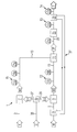
- the device 1 which preferably allows continuous mixing, comprises a first feed line 3 for a product concentrate K and a second feed line 5 for a dilution liquid W, such as water.
- a steam injector 7, 9 for introducing a first vapor stream D1 into the product concentrate K and a second vapor stream D2 into the dilution liquid W are respectively provided on the supply lines 3, 5.
- the vapor streams D1, D2 can heat the product concentrate K and the dilution liquid W to target temperatures T1, T2.
- the latter are preferably the same size, but may also be different depending on the product P.
- the vapor streams D1, D2 condense and mix with the product concentrate K and the dilution liquid W to aqueous mixed phases M1 and M2. In this case, the mass flows of the product concentrate K and of the first vapor stream D1 add to the mass flow of the first mixed phase M1, the mass flows of the dilution liquid W and the second vapor stream D2 to the mass flow of the second mixing phase M2.
- the device 1 further comprises a controllable mixing device 11, which may be, for example, a nozzle or an injector in order to combine the mixing phases M1, M2 in an adjustable ratio to a ready-mixed product P.
- the injectors 7, 9 are connected to the mixing device 11 by connecting lines 13, 15, to each of which a temperature measuring device 17a, 17b and a flow meter 19a, 19b is provided.
- the mixing device 11 may comprise sections of the connecting lines 13, 15 in order to adjust the mixing ratio of the mixing phases M1, M2 at these or in the region of the injectors 7, 9.
- a concentration meter 21 a is further provided to measure the concentration of a characteristic ingredient of the product P, such as a sugar content, in particular the Brix value of the mixed phase M1.
- a corresponding concentration meter 21 c is provided on a product line 23 leading away from the mixing device 11.
- a hot holding device 25 whose operation is known from the prior art and will therefore not be described in detail.
- it is preferably designed so that a minimum temperature or target temperature T3 for heat treatment of the product P, as in the area of the steam injectors 7, 9, is not exceeded.
- a further temperature gauge 17c is preferably provided in the outlet region of the hot-holding device 25. If the temperatures T1 and T2 of the mixed phases M1 and M2 are different, the temperature T3 of the mixed product P is preferably a mixing temperature between T1 and T2.
- the device 1 may comprise a heat recovery device 27 with a heat exchanger 29 on the output side with respect to the product flow and an input side heat exchanger 31 in order to heat-treat the product P prior to filling To remove heat and the dilution liquid W before it is introduced into the second injector 9 for the purpose of preheating.
- a heat recovery device 27 with a heat exchanger 29 on the output side with respect to the product flow and an input side heat exchanger 31 in order to heat-treat the product P prior to filling
- the second injector 9 for the purpose of preheating.
- heating energy can win back, wherein the preheating of the dilution liquid W in a production downtime with respect to the product quality is less critical than a preheating of the concentrate K, which would in principle be possible in an analogous manner.
- an associated, output-side temperature gauge 17d for determining an output-side product temperature T4 downstream of the output-side heat exchanger 29.
- the steam flow rates D1, D2 can be adjusted such that a predetermined for the heat treatment minimum temperature T1, T2 in the product concentrate K and in the dilution liquid W is achieved and that the product concentrate K is diluted to a suitable concentration for subsequent mixing. By dilution, a desired concentration of the blended product P can be more accurately adjusted.
- a control device which makes it possible to adjust the steam flow rates D1, D2 in dependence on the measurement results of the measuring devices 17a, 17b, 19a, 19b and 21a by means of the injectors 7, 9 and / or the adjusting device 33.
- the concentration meter 21 a could also only have a control function.
- the output-side concentration meter 21 c for the blended product P to monitor and / or adjust not only the steam flow rates D1, D2 but also the flow rates of the mixed phases M1, M2 for mixing the product P in the mixing device 11th ,
- steam D is for example provided under an overpressure of 2 bar and distributed to the first and second steam flow D1, D2, wherein the second steam flow D2 could be, for example, four times to six times greater than the first steam flow D1.
- vapor streams D1, D2 are continuously and simultaneously fed into the injectors 7, 9 and the product concentrate K and the fresh water W is supplied with steam D.
- a treatment temperature T1, T2 of 80 to 140 ° C, preferably from 90 to 100 ° C, in or behind the injectors 7, 9 reach and monitor with the temperature meters 17a, 17b.
- the flow through the connecting lines 13, 15 can be measured.
- concentration measurement in the mixing phase M1 in which, for example, a reduction of the Brix value by 10% compared to the initial concentration of the product concentrate K could be determined, by adjusting the flow rates of the mixed phases M1, M2 the desired concentration value of the mixed product P to adjust.
- the concentration meter 21c allows continuous monitoring of the mixed product P and any necessary correction of the flow rates D1, D2, M1 and / or M2.
- the flow rates of the supplied concentrate K and the dilution liquid W can be changed on this basis.
- the blended product P can be fed continuously to a cooling unit, an optional downstream buffer tank and finally to a filling machine.
- both the steam supply D and the supply of the product concentrate K and the dilution liquid W can be interrupted quickly, so that undesired heating in the device 1 stationary product concentrate K or a mixed phase, such as the mixed phase M1 , or the blended product P can be avoided.
- the device 1 of the invention reacts almost instantaneously and eliminates the need for an additional product return cycle during a production standstill and / or avoids quality degradation due to excessive heating of the product components.
- the inventive device 1 and the inventive method are suitable for a variety of liquid products, especially for commercial drinks, such as fruit juices and the like.
Landscapes
- Life Sciences & Earth Sciences (AREA)
- Engineering & Computer Science (AREA)
- Wood Science & Technology (AREA)
- Zoology (AREA)
- Chemical & Material Sciences (AREA)
- Food Science & Technology (AREA)
- Polymers & Plastics (AREA)
- Non-Alcoholic Beverages (AREA)
- Dairy Products (AREA)
- Apparatus For Making Beverages (AREA)
Description
- Die Erfindung betrifft eine Vorrichtung und ein Verfahren zum Ausmischen und Wärmebehandeln eines flüssigen Produkts, insbesondere eines Getränks.
- Fertiggetränke können durch Zusammenführen eines Produktkonzentrats und einer Verdünnungsflüssigkeit, wie beispielsweise Wasser, in einem vorgegebenen Mischungsverhältnis sowohl im Batch-Betrieb als auch als kontinuierliche Teilproduktströme ausgemischt werden. Eine thermische Behandlung zur Gewährleistung einer bestimmten Haltbarkeit oder Produktqualität erfolgt meist nach dem Ausmischen des Produkts.
- Bei dieser Vorgehensweise ist jedoch weder ein schnelles Anfahren noch ein schnelles Herunterfahren der Anlage bei einem Stillstand einer im Produktstrom nachfolgenden Fülleinheit möglich. Dies bedingt einen erheblichen apparativen Aufwand für Produktzwischenspeicher und/oder verursacht Produktverluste.
- Alternativ schlägt die
WO 02/094040 A1 - Die
US 4640840 A beschreibt eine Produktionsanlage zum thermischen Behandeln und Mischen zweier Komponenten eines flüssigen Lebensmittels, wie beispielsweise einer Suppe. - Beide Komponenten werden mittels Dampfinjektion in je einer zugeordneten Leitung thermisch behandelt und in einer Warmhaltevorrichtung auf einer jeweils zugeordneten Behandlungstemperatur gehalten. Nach Abkühlung werden die Produktkomponenten jeweils in einem Puffertank gespeichert. Die Ausgänge dieser Puffertanks führen zu einer Mischeinheit, in der das Endprodukt ausgemischt wird.
- Die bedingt jedoch ebenfalls einen hohen apparativen Aufwand und kann die oben genannten Probleme bei einer Produktionsunterbrechung nicht zufriedenstellend lösen.
- Es besteht daher Bedarf für ein in dieser Hinsicht verbessertes Verfahren und eine gegenüber dem Stand der Technik vereinfachte Vorrichtung.
- Die gestellte Aufgabe wird mit einer Vorrichtung nach Anspruch 1 gelöst. Demnach umfasst diese eine erste Zuleitung zum Zuführen eines Produktkonzentrats; eine zweite Zuleitung zum Zuführen einer wässrigen Verdünnungsflüssigkeit zum Verdünnen des Produktkonzentrats; einen ersten Dampfinjektor, der an der ersten Zuleitung vorgesehen ist, um einen ersten Dampfmengenstrom in das Produktkonzentrat einzubringen; und einen zweiten Dampfinjektor, der an der zweiten Zuleitung vorgesehen ist, um einen zweiten Dampfmengenstrom in die Verdünnungsflüssigkeit einzubringen. Dadurch können das Produktkonzentrat und die Verdünnungsflüssigkeit gleichzeitig wärmebehandelt und verdünnt werden. Insbesondere das Produktkonzentrat kann dabei in eine für das Ausmischen besonders geeignete Konzentration verdünnt werden. Die Dampfinjektion lässt sich gut dosieren und bei einem Produktionsstillstand schnell unterbrechen, so dass unerwünscht lange Verweilzeiten des Produktkonzentrats bei hohen Temperaturen vermieden werden können. Die Dampfinjektion ermöglicht bei Bedarf einen Stop-And-Go-Betrieb, wodurch Produktpuffer entbehrlich werden oder zumindest nur in geringerem Umfang benötigt werden. Ferner können Produktverluste in Folge einer Produktüberhitzung vermieden werden. Die Dampfinjektoren können an ein gemeinsames Dampfversorgungssystem angeschlossen werden, wodurch der apparative Aufwand weiter reduziert werden kann. Insbesondere ist ein zusätzlicher Wärmetauscher für die Verdünnungsflüssigkeit entbehrlich.
- Die erfindungsgemäße Vorrichtung umfasst ferner eine Mischeinrichtung zum Mischen des mittels des ersten Dampfinjektors mit Dampf beaufschlagten Produktkonzentrats und der mittels des zweiten Dampfinjektors mit Dampf beaufschlagten Verdünnungsflüssigkeit. Dadurch werden die auf diese Weise wärmebehandelten und verdünnten Teilproduktströme beim Zusammenführen in einem vorgegeben Mischungsverhältnis ausgemischt werden. Eine separate Ausmischanlage ist daher entbehrlich. Somit lässt sich Investitionskosten, Wartungskosten und Platzbedarf reduzieren. Ferner ist eine Einstelleinrichtung vorhanden, um den ersten und den zweiten Dampfmengenstrom einzustellen. Dadurch lässt sich eine Mindesttemperatur zur Wärmebehandlung im Konzentrat und in der Verdünnungsflüssigkeit einhalten sowie insbesondere in dem Konzentrat gleichzeitig eine für das Ausmischen geeignete Verdünnung einstellen.
- Bei einer besonders günstige Ausgestaltung der erfindungsgemäßen Vorrichtung ist zwischen dem ersten Dampfinjektor und der Mischeinrichtung ein Messgerät zur Bestimmung der Konzentration eines für die Qualität des Produkts charakteristischen Inhaltsstoffs in dem mit Dampf beaufschlagten Produktkonzentrat vorgesehen, insbesondere zur Bestimmung eines Zuckergehalts. Damit kann die Konzentration des mit dem kondensierten ersten Dampfmengenstrom verdünnten Produktkonzentrats gemessen werden und ein für das nachfolgende Ausmischen günstiger Wertebereich eingehalten werden. Zu diesem Zweck kann beispielsweise der erste
- Dampfmengenstrom in Abhängigkeit von der mit dem Konzentrationsmessgerät hinter dem ersten Dampfinjektor gemessenen Konzentration eingestellt werden.
- Vorzugsweise ist zwischen dem ersten Dampfinjektor und der Mischeinrichtung und zwischen dem zweiten Dampfinjektor und der Mischeinrichtung jeweils ein Durchflussmessgerät und eine Temperaturmessgerät zur Überwachung des mit Dampf beaufschlagten Konzentrats und der mit Dampf beaufschlagten Verdünnungsflüssigkeit vorgesehen. Dadurch kann sowohl die Qualität der Wärmebehandlung als auch das Mischungsverhältnis im ausgemischten Produkt überwacht oder eingestellt werden.
- Vorzugsweise ist ferner eine der Mischeinrichtung nach geschaltete Heißhalteeinrichtung vorgesehen. Dadurch kann eine Wärmebehandlung bis zum Erreichen einer gegebenenfalls erforderlichen Gesamtbehandlungsdauer verlängert werden. Somit kann die Wärmebehandlung auch bei einem unveränderten ersten Dampfmengenstrom an eine bestimmte Qualitätsanforderung, beispielsweise zur Pasteurisierung oder Sterilisierung, angepasst werden.
- Die gestellte Aufgabe wird ferner mit einem Verfahren nach Anspruch 5 gelöst. Dieses umfasst folgende Schritte: a) Bereitstellen eines Produktkonzentrats; b) Bereitstellen einer wässrigen Verdünnungsflüssigkeit zum Verdünnen des Produktkonzentrats; c) Bereitstellen von Dampf; d) Einstellen eines ersten und eines zweiten Dampfmengenstroms; e) Einbringen eines ersten Dampfstroms in das bereit gestellte Produktkonzentrat, um dieses thermisch zu behandeln und zu verdünnen; und f) Einbringen eines zweiten Dampfstroms in die bereitgestellte Verdünnungsflüssigkeit, um diese thermisch zu behandeln und zu verdünnen. Die Dampfströme kondensieren und vermischen sich mit dem Produktkonzentrat und der Verdünnungsflüssigkeit zu wässrigen Mischphasen. Hierbei addieren sich die Massenströme des Produktkonzentrats und des ersten Dampfstroms zum Massenstrom einer ersten Mischphase, die Massenströme der Verdünnungsflüssigkeit und des zweiten Dampfstroms zum Massenstrom einer zweiten Mischphase. Beide Massenströme werden miteinander gemischt.
- Somit können zwei Produktionsprozesse, nämlich eine thermische Behandlung und ein Einstellen einer für das Ausmischen geeigneten Verdünnung in einem Verfahren kombiniert werden.
- Die Dampfinjektion eignet sich außerdem für eine Vielzahl unterschiedlicher Produkte, beispielsweise auch für faserhaltige Produkte oder solche mit Fruchtstücken.
- Vorzugsweise werden das Produktkonzentrat und die Verdünnungsflüssigkeit als kontinuierliche Ströme bereit gestellt und parallel geschaltet mit Dampf beaufschlagt. Somit können beide Ströme gleichzeitig oder zumindest zeitlich überlappend behandelt und verdünnt werden. Die Ströme und die Dampfzufuhr können bei Bedarf schnell unterbrochen werden, um eine unerwünschte Erwärmung des Konzentrats zu vermeiden.
- Bei einer besonders günstigen Ausgestaltung des Verfahrens wird die Konzentration eines für die Qualität des Produkts charakteristischen Inhaltsstoffs in dem mit Dampf beaufschlagten Produktkonzentrat, insbesondere zur Bestimmung eines Zuckergehalts, nach Kondensation des eingebrachten Dampfs gemessen. Somit kann der eingebrachte Dampfmengenstrom bei der Konzentrationsmessung auf einfache Weise berücksichtigt werden und die Konzentration mit hoher Genauigkeit gemessen werden. Vorzugsweise wird hierbei ein Brix-Wert gemessen.
- Vorzugsweise werden ein Mengenstrom des mit Dampf beaufschlagten Produktkonzentrats und ein Mengenstrom der mit Dampf beaufschlagten Verdünnungsflüssigkeit jeweils nach Kondensation des eingebrachten Dampfs gemessen. Dadurch kann die eingebrachte Dampfmenge auf einfache Weise im Rahmen einer Summenmessung zusammen mit dem bereitgestellten Mengenstrom des Produktkonzentrats und der Verdünnungsflüssigkeit berücksichtigt werden. Es wäre jedoch auch möglich, den ersten und den zweiten Dampfmengenstrom jeweils gesondert zu messen, beispielsweise beim Einleiten in die Dampfinjektoren, ebenso die Mengenströme des Produktkonzentrats und der Verdünnungsflüssigkeit vor dem Einleiten des Dampfs.
- Vorzugsweise wird das Verhältnis der Mengenströme in Abhängigkeit der im ausgemischten Produkt gemessenen Konzentration eines für die Qualität des Produkts charakteristischen Inhaltsstoffs, insbesondere eines Zuckergehalts, eingestellt. Dadurch lässt sich die Produktqualität während des Ausmischens fortlaufend an eine Vorgabe anpassen. Besonders geeignet als Kontrollparameter ist hierbei der Brix-Wert.
- Vorzugsweise werden das mit Dampf beaufschlagte Konzentrat und die Verdünnungsflüssigkeit in Form erster und zweiter wässriger Mischphasen in einem vorgegeben Mischungsverhältnis, insbesondere als gemessenen Mengenströme, zusammen geführt, um das Produkt auszumischen. Dadurch lässt sich eine vorgegebene Produktqualität auf einfache Weise einstellen.
- Bei einer vorteilhaften Ausgestaltung wird durch das Einbringen des Dampfes in dem Produktkonzentrat und in der Verdünnungsflüssigkeit eine Mindesttemperatur, insbesondere zur Pasteurisierung oder Sterilisierung des Produkts, erreicht. Dadurch wird eine separate Erwärmung des ausgemischten Produkts entbehrlich oder zumindest im Umfang reduziert. Folglich sinken auch Produktverluste aufgrund einer unerwünschten Überhitzung des fertig ausgemischten Produkts in Folge von Produktionsstillständen.
- Vorzugsweise wird das ausgemischte Produkt unter Einhaltung einer Mindesttemperatur, insbesondere zur Pasteurisierung oder Sterilisierung des Produkts, heiß gehalten. Dadurch können auch Produkte, die eine vergleichsweise lange Behandlungszeit erfordern, mit einem hohen Durchsatz wärmebehandelt, verdünnt und ausgemischt werden. Somit lässt sich auch in diesen Fällen eine vorgegebene Ausmischung exakt einhalten.
- Bei einer besonders günstigen Ausgestaltung des Verfahrens wird dem ausgemischten und wärmebehandelten Produkt entzogene Wärme zum Vorwärmen der Verdünnungsflüssigkeit zurück geführt. Dadurch lässt sich Wärmeenergie effizient zurück gewinnen und der bezüglich einer potentiellen Überhitzung unkritischen Verdünnungsflüssigkeit zuführen. Die Vorrichtung lässt sich somit kostengünstig und ohne Einschränkung der Produktqualität bei einem Produktionsstillstand betreiben.
- Eine bevorzugte Ausführungsform der erfindungsgemäßen Vorrichtung ist in der Zeichnung dargestellt. Die einzige Figur zeigt ein Schema der Vorrichtung.
- Demnach umfasst die erfindungsgemäße Vorrichtung 1, die vorzugsweise ein kontinuierliches Ausmischen ermöglicht, eine erste Zuleitung 3 für ein Produktkonzentrat K und eine zweite Zuleitung 5 für eine Verdünnungsflüssigkeit W, wie beispielsweise Wasser. An den Zuleitungen 3, 5 ist jeweils ein Dampfinjektor 7, 9 zum Einbringen eines ersten Dampfstroms D1 in das Produktkonzentrat K und eines zweiten Dampfstroms D2 in die Verdünnungsflüssigkeit W vorgesehen. Die Dampfströme D1, D2 können das Produktkonzentrat K und die Verdünnungsflüssigkeit W auf Zieltemperaturen T1, T2 aufheizen. Letztere sind vorzugsweise gleich groß, können jedoch je nach Produkt P auch unterschiedlich sein. Die Dampfströme D1, D2 kondensieren und vermischen sich mit dem Produktkonzentrat K und der Verdünnungsflüssigkeit W zu wässrigen Mischphasen M1 und M2. Hierbei addieren sich die Massenströme des Produktkonzentrats K und des ersten Dampfstroms D1 zum Massenstrom der ersten Mischphase M1, die Massenströme der Verdünnungsflüssigkeit W und des zweiten Dampfstroms D2 zum Massenstrom der zweiten Mischphase M2.
- Die Vorrichtung 1 umfasst ferner eine steuerbare Mischeinrichtung 11, die beispielsweise eine Düse oder ein Injektor sein kann, um die Mischphasen M1, M2 in einem einstellbaren Verhältnis zu einem fertig ausgemischten Produkt P zusammenzuführen. Die Injektoren 7, 9 sind mit der Mischeinrichtung 11 durch Verbindungsleitungen 13, 15 verbunden, wobei an diesen jeweils eine Temperaturmesseinrichtung 17a, 17b und ein Durchflussmesser 19a, 19b vorgesehen ist. Es versteht sich von selbst, dass die Mischeinrichtung 11 Abschnitte der Verbindungsleitungen 13, 15 umfassen kann, um an diesen oder im Bereich der Injektoren 7, 9 das Mischungsverhältnis der Mischphasen M1, M2 einzustellen.
- An der Verbindungsleitung 13 für die Mischphase M1 ist ferner ein Konzentrationsmesser 21 a vorgesehen, um die Konzentration eines charakteristischen Inhaltsstoffs des Produkts P zu messen, wie beispielsweise einen Zuckergehalt, insbesondere den Brix-Wert der Mischphase M1. Ein entsprechender Konzentrationsmesser 21c ist an einer von der Mischeinrichtung 11 weg führenden Produktleitung 23 vorgesehen. Diese wiederum führt zu einer Heißhalteeinrichtung 25, deren Funktionsweise aus dem Stand der Technik bekannt ist und daher nicht näher beschrieben wird. Sie ist jedoch vorzugsweise so ausgebildet, dass eine Mindesttemperatur oder Zieltemperatur T3 zur Wärmebehandlung des Produkts P, wie im Bereich der Dampfinjektoren 7, 9, nicht unterschritten wird. Vorzugsweise ist zur Temperaturkontrolle ein weiterer Temperaturmesser 17c im Ausgangsbereich der Heißhaltevorrichtung 25 vorgesehen. Sind die Temperaturen T1 und T2 der Mischphasen M1 und M2 unterschiedlich, so ist die Temperatur T3 des ausgemischten Produkts P vorzugsweise eine Mischtemperatur zwischen T1 und T2.
- Optional kann die erfindungsgemäße Vorrichtung 1 eine Wärmerückführeinrichtung 27 mit einem bezüglich des Produktstroms ausgangsseitigen Wärmetauscher 29 und einem eingangsseitigen Wärmetauscher 31 umfassen, um dem wärmebehandelten Produkt P vor der Abfüllung Wärme zu entziehen und der Verdünnungsflüssigkeit W vor dem Einleiten in den zweiten Injektor 9 zwecks Vorwärmung zuzuführen. Somit lässt sich Heizenergie zurück gewinnen, wobei die Vorwärmung der Verdünnungsflüssigkeit W bei einem Produktionsstillstand bezüglich der Produktqualität unkritischer ist als eine Vorwärmung des Konzentrats K, die prinzipiell in analoger Weise möglich wäre. Dargestellt ist ferner ein zugehöriger, ausgangsseitiger Temperaturmesser 17d zum Ermitteln einer ausgangsseitigen Produkttemperatur T4 stromabwärts des ausgangsseitigen Wärmetauschers 29.
- Die Dampfmengenströme D1, D2, die vorzugsweise als Massenströme (Masse pro Zeiteinheit) definiert sind, können an den Injektoren 7, 9 oder an einer geeigneten Einstelleinrichtung 33 eingestellt werden. Im Beispiel wird diese von einer gemeinsamen Dampfleitung 35 versorgt und ist mit den Injektoren 7, 9 über Verteilerleitungen 37, 39 verbunden. Es versteht sich jedoch von selbst, dass für jeden Injektor 7, 9 eine getrennte Dampfversorgung möglich wäre. Entscheidend ist, dass die Dampfmengenströme D1, D2 eingestellt werden können, und dass die Injektoren 7, 9 im Parallelbetrieb mit Dampf D versorgt werden können, so dass sowohl das Produktkonzentrat K als auch die Verdünnungsflüssigkeit W im Wesentlichen gleichzeitig mit Dampf D beaufschlagt werden können.
- Die Dampfmengenströme D1, D2 können derart eingestellt werden, dass eine für die Wärmebehandlung vorgegebene Mindesttemperatur T1, T2 im Produktkonzentrat K und in der Verdünnungsflüssigkeit W erreicht wird und dass das Produktkonzentrat K auf eine für das nachfolgende Ausmischen geeignete Konzentration verdünnt wird. Durch die Verdünnung lässt sich eine gewünschte Konzentration des ausgemischten Produkts P exakter einstellen.
- Nicht dargestellt ist eine vorzugsweise vorgesehene Regeleinrichtung, die es ermöglicht, die Dampfmengenströme D1, D2 in Abhängigkeit von den Messergebnissen der Messeinrichtungen 17a, 17b, 19a, 19b und 21 a mit Hilfe der Injektoren 7, 9 und/oder der Einstelleinrichtung 33 einzustellen. Der Konzentrationsmesser 21 a könnte allerdings auch lediglich eine Kontrollfunktion haben. In die Regelung eingebunden ist vorzugsweise der ausgangsseitige Konzentrationsmesser 21 c für das ausgemischte Produkt P, um nicht nur die Dampfmengenströme D1, D2 zu überwachen und/oder einzustellen sondern auch die Mengenströme der Mischphasen M1, M2 für das Ausmischen des Produkts P in der Mischeinrichtung 11.
- Mit der erfindungsgemäßen Vorrichtung 1 kann wie folgt gearbeitet werden:
- Das Produktkonzentrat K könnte beispielsweise mit einem Brix-Wert von 40 bis 60°Bx und bei Raumtemperatur dem ersten Injektor 7 kontinuierlich zugeführt werden. Entsprechend könnte Frischwasser W als Verdünnungsflüssigkeit mit einer Temperatur von beispielsweise 10 bis 20°C kontinuierlich dem zweiten Injektor 9 zugeführt werden. Optional ist eine Vorwärmung in dem eingangsseitigen Wärmetauscher 31 denkbar. Der Mengenstrom des Frischwassers W könnte beispielsweise um das dreifache bis Vierfache höher sein als der Mengenstrom des Produktkonzentrats K, um einen Brix-Wert von beispielsweise 10°Bx im ausgemischten Produkt P einzustellen.
- Über die Dampfleitung 35 wird Wasserdampf D beispielsweise unter einem Überdruck von 2 bar bereitgestellt und auf den ersten und zweiten Dampfmengenstrom D1, D2 verteilt, wobei der zweite Dampfmengenstrom D2 beispielsweise um das Vierfache bis Sechsfache größer sein könnte als der erste Dampfmengenstrom D1.
- Die Dampfströme D1, D2 werden kontinuierlich und gleichzeitig in die Injektoren 7, 9 geleitet und das Produktkonzentrat K und das Frischwasser W mit Dampf D beaufschlagt. Hierdurch lässt sich beispielsweise eine Behandlungstemperatur T1, T2 von 80 bis 140°C, vorzugsweise von 90 bis 100°C, in oder hinter den Injektoren 7, 9 erreichen und mit den Temperaturmessern 17a, 17b überwachen.
- Nach Kondensation des Dampfes D in den Injektoren 7, 9 und/oder den Verbindungsleitungen 13, 15 kann der Durchfluss durch die Verbindungsleitungen 13, 15 gemessen werden. In Kombination mit der Konzentrationsmessung in der Mischphase M1, bei der beispielsweise eine Reduzierung des Brix-Werts um 10% gegenüber der Ausgangskonzentration des Produktkonzentrats K festgestellt werden könnte, lässt sich durch Einstellen der Mengenströme der Mischphasen M1, M2 der gewünschte Konzentrationswert des ausgemischten Produkts P einstellen. Hierbei ermöglicht der Konzentrationsmesser 21c eine kontinuierliche Überwachung des ausgemischten Produkts P und eine gegebenenfalls notwendige Korrektur der Mengenströme D1, D2, M1 und/oder M2. Selbstverständlich lassen sich auch die Mengenströme des zugeführten Konzentrats K und der Verdünnungsflüssigkeit W auf dieser Grundlage verändern.
- Das ausgemischte Produkt P kann kontinuierlich einer Kühleinheit, einem gegebenenfalls nachfolgenden Puffertank und schließlich einer Füllmaschine zugeführt werden.
- Bei einem Produktionsstillstand, insbesondere in der Fülleinheit, kann sowohl die Dampfzufuhr D als auch die Zufuhr des Produktkonzentrats K und der Verdünnungsflüssigkeit W schnell unterbrochen werden, so dass eine unerwünschte Erwärmung in der Vorrichtung 1 stehenden Produktkonzentrats K oder einer Mischphase, wie beispielsweise der Mischphase M1, oder des ausgemischten Produkts P vermieden werden kann. Im Gegensatz zu einem Wärmeübergang in herkömmlichen Wärmetauschern reagiert die erfindungsgemäße Vorrichtung 1 nahezu verzögerungsfrei und erübrigt einen zusätzlichen Produktrückführkreislauf während eines Produktionsstillstands und/oder vermeidet Qualitätseinbußen durch eine übermäßige Erwärmung vom Produktbestandteilen.
- Die erfindungsgemäße Vorrichtung 1 und das erfindungsgemäße Verfahren eignen sich für eine Vielzahl flüssiger Produkte, insbesondere für handelsübliche Getränke, wie beispielsweise Fruchtsäfte und dergleichen.
Claims (12)
- Vorrichtung (1) zum Ausmischen und Wärmebehandeln eines flüssigen Produkts (P), insbesondere eines Getränks, mit:- einer ersten Zuleitung (3) zum Bereitstellen eines Produktkonzentrats (K);- einer zweiten Zuleitung (5) zum Bereitstellen einer wässrigen Verdünnungsflüssigkeit (W) zum Verdünnen des Produktkonzentrats;- einem ersten Dampfinjektor (7), der an der ersten Zuleitung vorgesehen ist, um einen ersten Dampfmengenstrom (D1) in das Produktkonzentrat einzubringen; und- einem zweiten Dampfinjektor (9), der an der zweiten Zuleitung vorgesehen ist, um einen zweiten Dampfmengenstrom (D2) in die Verdünnungsflüssigkeit einzubringen, und- einer Einstelleinrichtung (33), um den ersten und den zweiten Dampfmengenstrom (D1, D2) einzustellen, und einer Mischeinrichtung (11) zum Mischen des mittels des ersten Dampfinjektors (7) mit Dampf (D1) beaufschlagten Produktkonzentrats (K) und der mittels des zweiten Dampfinjektors (9) mit Dampf (D2) beaufschlagten Verdünnungsflüssigkeit (W).
- Vorrichtung nach Anspruch 1, bei der zwischen dem ersten Dampfinjektor (7) und der Mischeinrichtung (11) ein Messgerät (21a) zur Bestimmung der Konzentration eines für die Qualität des Produkts (P) charakteristischen Inhaltsstoffs in dem mit Dampf beaufschlagten Produktkonzentrat (M1) vorgesehen ist, insbesondere zur Bestimmung eines Zuckergehalts.
- Vorrichtung nach Anspruch 1 oder 2, bei der zwischen dem ersten Dampfinjektor (7) und der Mischeinrichtung (11) und zwischen dem zweiten Dampfinjektor (9) und der Mischeinrichtung (11) jeweils ein Durchflussmessgerät (19a, 19b) und eine Temperaturmessgerät (17a, 17b) zur Überwachung des mit Dampf beaufschlagten Konzentrats (M1) und der mit Dampf beaufschlagten Verdünnungsflüssigkeit (M2) vorgesehen ist.
- Vorrichtung nach Anspruch 2 oder 3, bei der ferner eine der Mischeinrichtung (11) nachgeschaltete Heißhalteeinrichtung (25) vorgesehen ist.
- Verfahren zum Ausmischen und Wärmebehandeln eines flüssigen Produkts (P), insbesondere eines Getränks, mit folgenden Schritten:a) Bereitstellen eines Produktkonzentrats (K);b) Bereitstellen einer wässrigen Verdünnungsflüssigkeit (W) zum Verdünnen des Produktkonzentrats;c) Bereitstellen von Dampf (D);d) Einstellen eines ersten und eines zweiten Dampfmengenstroms (D1, D2);e) Einbringen des ersten Dampfmengenstroms (D1) in das bereit gestellte Produktkonzentrat, um dieses thermisch zu behandeln und zu verdünnen; undf) Einbringen des zweiten Dampfmengenstroms (D2) in die bereitgestellte Verdünnungsflüssigkeit, um diese thermisch zu behandeln und zu verdünnen,wobei das mit Dampf (D) beaufschlagte Produktkonzentrat (K) und die mit Dampf (D) beaufschlagte Verdünnungsflüssigkeit (W) in Form erster und zweiter wässriger Mischphasen (M1, M2) in einem vorgegeben Mischungsverhältnis, insbesondere als nach Kondensation des Dampfes (D) gemessenen Mengenströme, zusammen geführt werden, um das Produkt (P) auszumischen.
- Verfahren nach Anspruch 5, bei dem das Produktkonzentrat (K) und die Verdünnungsflüssigkeit (W) als kontinuierliche Ströme bereit gestellt werden und parallel geschaltet mit Dampf (D) beaufschlagt werden.
- Verfahren nach Anspruch 5 oder 6, bei dem die Konzentration eines für die Qualität des Produkts charakteristischen Inhaltsstoffs in dem mit Dampf (D) beaufschlagten Produktkonzentrat (K), insbesondere zur Bestimmung eines Zuckergehalts, nach Kondensation des eingebrachten Dampfs (D) gemessen wird.
- Verfahren nach wenigstens einem der Ansprüche 5 bis 7, bei dem ein erster Mengenstrom des mit Dampf beaufschlagten Produktkonzentrats (M1) und ein zweiter Mengenstrom der mit Dampf beaufschlagten Verdünnungsflüssigkeit (M2) jeweils nach Kondensation des eingebrachten Dampfs (D) gemessen wird.
- Verfahren nach Anspruch 8, bei dem das Verhältnis des ersten und zweiten Mengenstroms in Abhängigkeit der im ausgemischten Produkt (P) gemessenen Konzentration eines für die Qualität des Produkts charakteristischen Inhaltsstoffs, insbesondere eines Zuckergehalts, eingestellt wird.
- Verfahren nach wenigstens einem der Ansprüche 5 bis 9, bei dem durch das Einbringen des Dampfes (D) in dem Produktkonzentrat (K) und in der Verdünnungsflüssigkeit (W) eine Mindesttemperatur (T1, T2), insbesondere zur Pasteurisierung oder Sterilisierung des Produkts (P), erreicht wird.
- Verfahren nach wenigstens einem der Ansprüche 5 bis 10, bei dem das ausgemischte Produkt (P) unter Einhaltung einer Mindesttemperatur (T3), insbesondere zur Pasteurisierung oder Sterilisierung des Produkts, heiß gehalten wird.
- Verfahren nach wenigstens einem der Ansprüche 5 bis 11 bei dem dem ausgemischten und wärmebehandelten Produkt (P) entzogene Wärme zum Vorwärmen der Verdünnungsflüssigkeit (W) zurück geführt wird.
Applications Claiming Priority (1)
| Application Number | Priority Date | Filing Date | Title |
|---|---|---|---|
| DE102010031477A DE102010031477A1 (de) | 2010-07-16 | 2010-07-16 | Vorrichtung und Verfahren zum Ausmischen und Wärmebehandeln eines flüssigen Produkts |
Publications (2)
| Publication Number | Publication Date |
|---|---|
| EP2409582A1 EP2409582A1 (de) | 2012-01-25 |
| EP2409582B1 true EP2409582B1 (de) | 2014-10-08 |
Family
ID=44862216
Family Applications (1)
| Application Number | Title | Priority Date | Filing Date |
|---|---|---|---|
| EP11164306.0A Not-in-force EP2409582B1 (de) | 2010-07-16 | 2011-04-29 | Vorrichtung und Verfahren zum Ausmischen und Wärmebehandeln eines flüssigen Produkts |
Country Status (6)
| Country | Link |
|---|---|
| US (1) | US20120015088A1 (de) |
| EP (1) | EP2409582B1 (de) |
| BR (1) | BRPI1103574A2 (de) |
| DE (1) | DE102010031477A1 (de) |
| DK (1) | DK2409582T3 (de) |
| ES (1) | ES2522569T3 (de) |
Families Citing this family (4)
| Publication number | Priority date | Publication date | Assignee | Title |
|---|---|---|---|---|
| US20160128374A1 (en) * | 2013-05-31 | 2016-05-12 | Tetra Laval Holdings & Finance S.A. | A method and system for providing a heat treated liquid product |
| US10209141B2 (en) * | 2013-05-31 | 2019-02-19 | Tetra Laval Holdings & Finance S.A. | Determining the degree of heat treatment of a liquid product |
| WO2015162041A1 (en) * | 2014-04-22 | 2015-10-29 | Tetra Laval Holdings & Finance S.A. | System and method for processing liquid or semi-liquid food products with particles |
| EP4159045B8 (de) * | 2021-09-29 | 2024-10-30 | Capristo Steam Technology GmbH | Verfahren zur herstellung einer fluiden komponente einer lebensmittelgrundmasse und vorrichtung hierzu |
Family Cites Families (14)
| Publication number | Priority date | Publication date | Assignee | Title |
|---|---|---|---|---|
| FR2543410B1 (fr) * | 1983-03-29 | 1988-06-24 | Torterotot Roland | Procede de reconstitution et de traitement thermique de produits alimentaires liquides, et appareillage permettant de mettre en oeuvre ce procede |
| PH22174A (en) * | 1984-05-08 | 1988-06-28 | Unilever Nv | Food processing method |
| US4614661A (en) * | 1985-03-21 | 1986-09-30 | Kraft, Inc. | Methods and apparatus for sanitary steam injection |
| EP0247245A1 (de) * | 1986-05-23 | 1987-12-02 | The Procter & Gamble Company | Saftsterilisationsverfahren |
| GB8909779D0 (en) * | 1989-04-28 | 1989-06-14 | Procter & Gamble | Apparatus for the sterilization of fluid foods |
| US6799883B1 (en) * | 1999-12-20 | 2004-10-05 | Air Liquide America L.P. | Method for continuously blending chemical solutions |
| US6159519A (en) * | 1998-04-29 | 2000-12-12 | Buckeye Feed Mills, Inc. | Method for supplying steam to a grain processor |
| US7004355B1 (en) * | 2000-06-08 | 2006-02-28 | Beverage Works, Inc. | Beverage dispensing apparatus having drink supply canister holder |
| US6599546B2 (en) | 2001-05-18 | 2003-07-29 | The Coca Cola Company | Process and apparatus for in-line production of heat-processed beverage made from concentrate |
| SE521921C2 (sv) * | 2002-03-15 | 2003-12-16 | Tetra Laval Holdings & Finance | Metod för att upprätthålla aseptiska förhållanden i en juiceanläggning vid korta produktionsstopp |
| DE602005004558T2 (de) * | 2005-11-11 | 2009-01-22 | Gruppo Cimbali S.P.A. | Automatische Vorrichtung zum Erhitzen und Schäumen von Milch |
| US20080160149A1 (en) * | 2006-12-28 | 2008-07-03 | Maurice Nasrallah | Sterilization of Flowable Food Products |
| WO2010017280A1 (en) * | 2008-08-05 | 2010-02-11 | Techni-Blend, Inc. | Blending system |
| US8075302B1 (en) * | 2009-01-02 | 2011-12-13 | Mcclellan Luther W | Apparatus for optimally mixing and injecting a two part urethane foam |
-
2010
- 2010-07-16 DE DE102010031477A patent/DE102010031477A1/de not_active Withdrawn
-
2011
- 2011-04-29 EP EP11164306.0A patent/EP2409582B1/de not_active Not-in-force
- 2011-04-29 ES ES11164306.0T patent/ES2522569T3/es active Active
- 2011-04-29 DK DK11164306.0T patent/DK2409582T3/en active
- 2011-07-14 BR BRPI1103574-9A patent/BRPI1103574A2/pt not_active Application Discontinuation
- 2011-07-15 US US13/183,525 patent/US20120015088A1/en not_active Abandoned
Also Published As
| Publication number | Publication date |
|---|---|
| BRPI1103574A2 (pt) | 2012-12-04 |
| US20120015088A1 (en) | 2012-01-19 |
| DE102010031477A1 (de) | 2012-01-19 |
| CN102334705A (zh) | 2012-02-01 |
| EP2409582A1 (de) | 2012-01-25 |
| ES2522569T3 (es) | 2014-11-17 |
| DK2409582T3 (en) | 2015-01-12 |
Similar Documents
| Publication | Publication Date | Title |
|---|---|---|
| EP2409582B1 (de) | Vorrichtung und Verfahren zum Ausmischen und Wärmebehandeln eines flüssigen Produkts | |
| EP2583596B1 (de) | Vorrichtung zur Ausgabe von Milch und Verfahren zum Erwärmen von Milch | |
| EP2571372B1 (de) | Anlage und verfahren zur pasteurisierung mindestens einer flüssigkeit | |
| EP3672779A1 (de) | Verfahren und vorrichtung zum erwärmen von kunststoffvorformlingen | |
| EP2567935B1 (de) | Verfahren und Vorrichtung zum Erhitzen eines flüssigen Produkts | |
| DE102010002407A1 (de) | Verfahren und Vorrichtung zum sterilen Abfüllen von zwei unterschiedlichen Produktströmen in einen Behälter | |
| EP2294952A1 (de) | Einrichtung zur Ausgabe von Milch und/oder Milchschaum | |
| DE102017113832A1 (de) | Verfahren und Vorrichtung zum Erzeugen von Milch-Luft-Emulsionen | |
| WO2010017888A1 (de) | Verfahren zum abfüllen eines aus wenigstens einer ersten und einer zweiten komponente bestehenden füllgutes | |
| EP0262300A2 (de) | Verfahren und Vorrichtung zur Herstellung einer Schokolademasse | |
| EP2798989A1 (de) | Getränkezubereitungsvorrichtung mit Mitteln zur Milcherhitzung sowie Betriebsverfahren | |
| EP2378895A2 (de) | Verfahren und vorrichtung zur herstellung eines produktes durch mikrogelierung und/oder mikropartikulierung eines ansatzes | |
| EP2388064B1 (de) | Vorrichtung und Verfahren zum Ausmischen von Getränken | |
| EP3503734B1 (de) | Verfahren und anordnung zur aseptischen erhitzung eines flüssigen produkts in einer wärmetauschereinheit der erhitzerzone einer uht-anlage | |
| EP1815774A1 (de) | Vorrichtung zur Ausgabe von Milch und Milchschaum | |
| EP3474682B1 (de) | Verfahren zum erhitzen eines konzentrats in einer anlage zum zerstäubungstrocknen und anlage zur durchführung des verfahrens | |
| EP3275317A1 (de) | Milchkaramellherstellung ohne kochen | |
| DE2303890C2 (de) | Verfahren zum Erhitzen von flüssigen Lebensmitteln | |
| EP3831456B1 (de) | Vorrichtung zur herstellung und bereitstellung von sterilwasser und verfahren zum betreiben der vorrichtung | |
| CN102334705B (zh) | 用于混合和热处理液体产品的装置和方法 | |
| EP0671129B1 (de) | Verfahren und Vorrichtung zur lebensmitteltechnischen Produktbehandlung | |
| EP1610618A1 (de) | Vorrichtung zum bereitstellen von flüssigen lebensmitteln | |
| DE102006038651B4 (de) | Verfahren und Vorrichtung zum kontinuierlichen Sterilisieren von Produkten mit sowohl stückigen als auch flüssigen Anteilen | |
| WO2016005109A1 (de) | Wärmebehandlungsvorrichtung sowie verfahren zur wärmebehandlung | |
| DE702521C (de) | Verfahren und Anlage zur Herstellung von Speisesenf |
Legal Events
| Date | Code | Title | Description |
|---|---|---|---|
| AK | Designated contracting states |
Kind code of ref document: A1 Designated state(s): AL AT BE BG CH CY CZ DE DK EE ES FI FR GB GR HR HU IE IS IT LI LT LU LV MC MK MT NL NO PL PT RO RS SE SI SK SM TR |
|
| AX | Request for extension of the european patent |
Extension state: BA ME |
|
| PUAI | Public reference made under article 153(3) epc to a published international application that has entered the european phase |
Free format text: ORIGINAL CODE: 0009012 |
|
| 17P | Request for examination filed |
Effective date: 20120222 |
|
| 17Q | First examination report despatched |
Effective date: 20131205 |
|
| RIC1 | Information provided on ipc code assigned before grant |
Ipc: A23L 2/46 20060101AFI20140428BHEP Ipc: A23L 3/22 20060101ALI20140428BHEP Ipc: A23L 3/18 20060101ALI20140428BHEP |
|
| GRAP | Despatch of communication of intention to grant a patent |
Free format text: ORIGINAL CODE: EPIDOSNIGR1 |
|
| INTG | Intention to grant announced |
Effective date: 20140606 |
|
| GRAS | Grant fee paid |
Free format text: ORIGINAL CODE: EPIDOSNIGR3 |
|
| GRAA | (expected) grant |
Free format text: ORIGINAL CODE: 0009210 |
|
| AK | Designated contracting states |
Kind code of ref document: B1 Designated state(s): AL AT BE BG CH CY CZ DE DK EE ES FI FR GB GR HR HU IE IS IT LI LT LU LV MC MK MT NL NO PL PT RO RS SE SI SK SM TR |
|
| REG | Reference to a national code |
Ref country code: GB Ref legal event code: FG4D Free format text: NOT ENGLISH |
|
| REG | Reference to a national code |
Ref country code: AT Ref legal event code: REF Ref document number: 690092 Country of ref document: AT Kind code of ref document: T Effective date: 20141015 Ref country code: CH Ref legal event code: EP Ref country code: CH Ref legal event code: NV Representative=s name: BOVARD AG, CH |
|
| REG | Reference to a national code |
Ref country code: IE Ref legal event code: FG4D Free format text: LANGUAGE OF EP DOCUMENT: GERMAN |
|
| REG | Reference to a national code |
Ref country code: ES Ref legal event code: FG2A Ref document number: 2522569 Country of ref document: ES Kind code of ref document: T3 Effective date: 20141117 |
|
| REG | Reference to a national code |
Ref country code: DE Ref legal event code: R096 Ref document number: 502011004587 Country of ref document: DE Effective date: 20141120 |
|
| REG | Reference to a national code |
Ref country code: NL Ref legal event code: T3 |
|
| REG | Reference to a national code |
Ref country code: SE Ref legal event code: TRGR |
|
| REG | Reference to a national code |
Ref country code: DK Ref legal event code: T3 Effective date: 20150108 |
|
| REG | Reference to a national code |
Ref country code: LT Ref legal event code: MG4D |
|
| PG25 | Lapsed in a contracting state [announced via postgrant information from national office to epo] |
Ref country code: PT Free format text: LAPSE BECAUSE OF FAILURE TO SUBMIT A TRANSLATION OF THE DESCRIPTION OR TO PAY THE FEE WITHIN THE PRESCRIBED TIME-LIMIT Effective date: 20150209 Ref country code: IS Free format text: LAPSE BECAUSE OF FAILURE TO SUBMIT A TRANSLATION OF THE DESCRIPTION OR TO PAY THE FEE WITHIN THE PRESCRIBED TIME-LIMIT Effective date: 20150208 Ref country code: NO Free format text: LAPSE BECAUSE OF FAILURE TO SUBMIT A TRANSLATION OF THE DESCRIPTION OR TO PAY THE FEE WITHIN THE PRESCRIBED TIME-LIMIT Effective date: 20150108 Ref country code: LT Free format text: LAPSE BECAUSE OF FAILURE TO SUBMIT A TRANSLATION OF THE DESCRIPTION OR TO PAY THE FEE WITHIN THE PRESCRIBED TIME-LIMIT Effective date: 20141008 Ref country code: FI Free format text: LAPSE BECAUSE OF FAILURE TO SUBMIT A TRANSLATION OF THE DESCRIPTION OR TO PAY THE FEE WITHIN THE PRESCRIBED TIME-LIMIT Effective date: 20141008 |
|
| PG25 | Lapsed in a contracting state [announced via postgrant information from national office to epo] |
Ref country code: GR Free format text: LAPSE BECAUSE OF FAILURE TO SUBMIT A TRANSLATION OF THE DESCRIPTION OR TO PAY THE FEE WITHIN THE PRESCRIBED TIME-LIMIT Effective date: 20150109 Ref country code: LV Free format text: LAPSE BECAUSE OF FAILURE TO SUBMIT A TRANSLATION OF THE DESCRIPTION OR TO PAY THE FEE WITHIN THE PRESCRIBED TIME-LIMIT Effective date: 20141008 Ref country code: CY Free format text: LAPSE BECAUSE OF FAILURE TO SUBMIT A TRANSLATION OF THE DESCRIPTION OR TO PAY THE FEE WITHIN THE PRESCRIBED TIME-LIMIT Effective date: 20141008 Ref country code: RS Free format text: LAPSE BECAUSE OF FAILURE TO SUBMIT A TRANSLATION OF THE DESCRIPTION OR TO PAY THE FEE WITHIN THE PRESCRIBED TIME-LIMIT Effective date: 20141008 Ref country code: PL Free format text: LAPSE BECAUSE OF FAILURE TO SUBMIT A TRANSLATION OF THE DESCRIPTION OR TO PAY THE FEE WITHIN THE PRESCRIBED TIME-LIMIT Effective date: 20141008 Ref country code: HR Free format text: LAPSE BECAUSE OF FAILURE TO SUBMIT A TRANSLATION OF THE DESCRIPTION OR TO PAY THE FEE WITHIN THE PRESCRIBED TIME-LIMIT Effective date: 20141008 |
|
| REG | Reference to a national code |
Ref country code: DE Ref legal event code: R097 Ref document number: 502011004587 Country of ref document: DE |
|
| PG25 | Lapsed in a contracting state [announced via postgrant information from national office to epo] |
Ref country code: SK Free format text: LAPSE BECAUSE OF FAILURE TO SUBMIT A TRANSLATION OF THE DESCRIPTION OR TO PAY THE FEE WITHIN THE PRESCRIBED TIME-LIMIT Effective date: 20141008 Ref country code: CZ Free format text: LAPSE BECAUSE OF FAILURE TO SUBMIT A TRANSLATION OF THE DESCRIPTION OR TO PAY THE FEE WITHIN THE PRESCRIBED TIME-LIMIT Effective date: 20141008 Ref country code: EE Free format text: LAPSE BECAUSE OF FAILURE TO SUBMIT A TRANSLATION OF THE DESCRIPTION OR TO PAY THE FEE WITHIN THE PRESCRIBED TIME-LIMIT Effective date: 20141008 Ref country code: RO Free format text: LAPSE BECAUSE OF FAILURE TO SUBMIT A TRANSLATION OF THE DESCRIPTION OR TO PAY THE FEE WITHIN THE PRESCRIBED TIME-LIMIT Effective date: 20141008 |
|
| PLBE | No opposition filed within time limit |
Free format text: ORIGINAL CODE: 0009261 |
|
| STAA | Information on the status of an ep patent application or granted ep patent |
Free format text: STATUS: NO OPPOSITION FILED WITHIN TIME LIMIT |
|
| 26N | No opposition filed |
Effective date: 20150709 |
|
| PG25 | Lapsed in a contracting state [announced via postgrant information from national office to epo] |
Ref country code: MC Free format text: LAPSE BECAUSE OF FAILURE TO SUBMIT A TRANSLATION OF THE DESCRIPTION OR TO PAY THE FEE WITHIN THE PRESCRIBED TIME-LIMIT Effective date: 20141008 Ref country code: LU Free format text: LAPSE BECAUSE OF FAILURE TO SUBMIT A TRANSLATION OF THE DESCRIPTION OR TO PAY THE FEE WITHIN THE PRESCRIBED TIME-LIMIT Effective date: 20150429 |
|
| GBPC | Gb: european patent ceased through non-payment of renewal fee |
Effective date: 20150429 |
|
| REG | Reference to a national code |
Ref country code: IE Ref legal event code: MM4A |
|
| PG25 | Lapsed in a contracting state [announced via postgrant information from national office to epo] |
Ref country code: GB Free format text: LAPSE BECAUSE OF NON-PAYMENT OF DUE FEES Effective date: 20150429 |
|
| REG | Reference to a national code |
Ref country code: FR Ref legal event code: ST Effective date: 20151231 |
|
| PG25 | Lapsed in a contracting state [announced via postgrant information from national office to epo] |
Ref country code: FR Free format text: LAPSE BECAUSE OF NON-PAYMENT OF DUE FEES Effective date: 20150430 Ref country code: SI Free format text: LAPSE BECAUSE OF FAILURE TO SUBMIT A TRANSLATION OF THE DESCRIPTION OR TO PAY THE FEE WITHIN THE PRESCRIBED TIME-LIMIT Effective date: 20141008 |
|
| PG25 | Lapsed in a contracting state [announced via postgrant information from national office to epo] |
Ref country code: IE Free format text: LAPSE BECAUSE OF NON-PAYMENT OF DUE FEES Effective date: 20150429 |
|
| PGFP | Annual fee paid to national office [announced via postgrant information from national office to epo] |
Ref country code: ES Payment date: 20160311 Year of fee payment: 6 |
|
| PGFP | Annual fee paid to national office [announced via postgrant information from national office to epo] |
Ref country code: NL Payment date: 20160411 Year of fee payment: 6 |
|
| PGFP | Annual fee paid to national office [announced via postgrant information from national office to epo] |
Ref country code: CH Payment date: 20160411 Year of fee payment: 6 |
|
| PG25 | Lapsed in a contracting state [announced via postgrant information from national office to epo] |
Ref country code: MT Free format text: LAPSE BECAUSE OF FAILURE TO SUBMIT A TRANSLATION OF THE DESCRIPTION OR TO PAY THE FEE WITHIN THE PRESCRIBED TIME-LIMIT Effective date: 20141008 |
|
| PG25 | Lapsed in a contracting state [announced via postgrant information from national office to epo] |
Ref country code: BG Free format text: LAPSE BECAUSE OF FAILURE TO SUBMIT A TRANSLATION OF THE DESCRIPTION OR TO PAY THE FEE WITHIN THE PRESCRIBED TIME-LIMIT Effective date: 20141008 Ref country code: SM Free format text: LAPSE BECAUSE OF FAILURE TO SUBMIT A TRANSLATION OF THE DESCRIPTION OR TO PAY THE FEE WITHIN THE PRESCRIBED TIME-LIMIT Effective date: 20141008 Ref country code: HU Free format text: LAPSE BECAUSE OF FAILURE TO SUBMIT A TRANSLATION OF THE DESCRIPTION OR TO PAY THE FEE WITHIN THE PRESCRIBED TIME-LIMIT; INVALID AB INITIO Effective date: 20110429 |
|
| REG | Reference to a national code |
Ref country code: AT Ref legal event code: MM01 Ref document number: 690092 Country of ref document: AT Kind code of ref document: T Effective date: 20160429 |
|
| PG25 | Lapsed in a contracting state [announced via postgrant information from national office to epo] |
Ref country code: BE Free format text: LAPSE BECAUSE OF NON-PAYMENT OF DUE FEES Effective date: 20150430 |
|
| PG25 | Lapsed in a contracting state [announced via postgrant information from national office to epo] |
Ref country code: AT Free format text: LAPSE BECAUSE OF NON-PAYMENT OF DUE FEES Effective date: 20160429 Ref country code: TR Free format text: LAPSE BECAUSE OF FAILURE TO SUBMIT A TRANSLATION OF THE DESCRIPTION OR TO PAY THE FEE WITHIN THE PRESCRIBED TIME-LIMIT Effective date: 20141008 |
|
| REG | Reference to a national code |
Ref country code: CH Ref legal event code: PL |
|
| REG | Reference to a national code |
Ref country code: NL Ref legal event code: MM Effective date: 20170501 |
|
| PG25 | Lapsed in a contracting state [announced via postgrant information from national office to epo] |
Ref country code: NL Free format text: LAPSE BECAUSE OF NON-PAYMENT OF DUE FEES Effective date: 20170501 |
|
| PG25 | Lapsed in a contracting state [announced via postgrant information from national office to epo] |
Ref country code: LI Free format text: LAPSE BECAUSE OF NON-PAYMENT OF DUE FEES Effective date: 20170430 Ref country code: CH Free format text: LAPSE BECAUSE OF NON-PAYMENT OF DUE FEES Effective date: 20170430 |
|
| REG | Reference to a national code |
Ref country code: ES Ref legal event code: FD2A Effective date: 20180626 |
|
| PG25 | Lapsed in a contracting state [announced via postgrant information from national office to epo] |
Ref country code: MK Free format text: LAPSE BECAUSE OF FAILURE TO SUBMIT A TRANSLATION OF THE DESCRIPTION OR TO PAY THE FEE WITHIN THE PRESCRIBED TIME-LIMIT Effective date: 20141008 |
|
| PG25 | Lapsed in a contracting state [announced via postgrant information from national office to epo] |
Ref country code: ES Free format text: LAPSE BECAUSE OF NON-PAYMENT OF DUE FEES Effective date: 20170430 |
|
| PG25 | Lapsed in a contracting state [announced via postgrant information from national office to epo] |
Ref country code: AL Free format text: LAPSE BECAUSE OF FAILURE TO SUBMIT A TRANSLATION OF THE DESCRIPTION OR TO PAY THE FEE WITHIN THE PRESCRIBED TIME-LIMIT Effective date: 20141008 |
|
| PGFP | Annual fee paid to national office [announced via postgrant information from national office to epo] |
Ref country code: DK Payment date: 20200414 Year of fee payment: 10 |
|
| PGFP | Annual fee paid to national office [announced via postgrant information from national office to epo] |
Ref country code: IT Payment date: 20200312 Year of fee payment: 10 |
|
| REG | Reference to a national code |
Ref country code: DK Ref legal event code: EBP Effective date: 20210430 |
|
| PG25 | Lapsed in a contracting state [announced via postgrant information from national office to epo] |
Ref country code: DK Free format text: LAPSE BECAUSE OF NON-PAYMENT OF DUE FEES Effective date: 20210430 |
|
| PGFP | Annual fee paid to national office [announced via postgrant information from national office to epo] |
Ref country code: SE Payment date: 20220310 Year of fee payment: 12 |
|
| PGFP | Annual fee paid to national office [announced via postgrant information from national office to epo] |
Ref country code: DE Payment date: 20220309 Year of fee payment: 12 |
|
| PG25 | Lapsed in a contracting state [announced via postgrant information from national office to epo] |
Ref country code: IT Free format text: LAPSE BECAUSE OF NON-PAYMENT OF DUE FEES Effective date: 20200429 |
|
| P01 | Opt-out of the competence of the unified patent court (upc) registered |
Effective date: 20230523 |
|
| REG | Reference to a national code |
Ref country code: DE Ref legal event code: R119 Ref document number: 502011004587 Country of ref document: DE |
|
| REG | Reference to a national code |
Ref country code: SE Ref legal event code: EUG |
|
| PG25 | Lapsed in a contracting state [announced via postgrant information from national office to epo] |
Ref country code: SE Free format text: LAPSE BECAUSE OF NON-PAYMENT OF DUE FEES Effective date: 20230430 Ref country code: DE Free format text: LAPSE BECAUSE OF NON-PAYMENT OF DUE FEES Effective date: 20231103 |
|
| PG25 | Lapsed in a contracting state [announced via postgrant information from national office to epo] |
Ref country code: IT Free format text: LAPSE BECAUSE OF NON-PAYMENT OF DUE FEES Effective date: 20210429 |