EP2361559A1 - Appareil de fixation chirurgicale - Google Patents
Appareil de fixation chirurgicale Download PDFInfo
- Publication number
- EP2361559A1 EP2361559A1 EP11167098A EP11167098A EP2361559A1 EP 2361559 A1 EP2361559 A1 EP 2361559A1 EP 11167098 A EP11167098 A EP 11167098A EP 11167098 A EP11167098 A EP 11167098A EP 2361559 A1 EP2361559 A1 EP 2361559A1
- Authority
- EP
- European Patent Office
- Prior art keywords
- fastener
- barrel portion
- mandrel
- distal end
- throughbore
- Prior art date
- Legal status (The legal status is an assumption and is not a legal conclusion. Google has not performed a legal analysis and makes no representation as to the accuracy of the status listed.)
- Granted
Links
Images


Classifications
-
- A—HUMAN NECESSITIES
- A61—MEDICAL OR VETERINARY SCIENCE; HYGIENE
- A61B—DIAGNOSIS; SURGERY; IDENTIFICATION
- A61B17/00—Surgical instruments, devices or methods, e.g. tourniquets
- A61B17/068—Surgical staplers, e.g. containing multiple staples or clamps
-
- A—HUMAN NECESSITIES
- A61—MEDICAL OR VETERINARY SCIENCE; HYGIENE
- A61B—DIAGNOSIS; SURGERY; IDENTIFICATION
- A61B17/00—Surgical instruments, devices or methods, e.g. tourniquets
- A61B17/064—Surgical staples, i.e. penetrating the tissue
-
- A—HUMAN NECESSITIES
- A61—MEDICAL OR VETERINARY SCIENCE; HYGIENE
- A61L—METHODS OR APPARATUS FOR STERILISING MATERIALS OR OBJECTS IN GENERAL; DISINFECTION, STERILISATION OR DEODORISATION OF AIR; CHEMICAL ASPECTS OF BANDAGES, DRESSINGS, ABSORBENT PADS OR SURGICAL ARTICLES; MATERIALS FOR BANDAGES, DRESSINGS, ABSORBENT PADS OR SURGICAL ARTICLES
- A61L31/00—Materials for other surgical articles, e.g. stents, stent-grafts, shunts, surgical drapes, guide wires, materials for adhesion prevention, occluding devices, surgical gloves, tissue fixation devices
- A61L31/14—Materials characterised by their function or physical properties, e.g. injectable or lubricating compositions, shape-memory materials, surface modified materials
- A61L31/148—Materials at least partially resorbable by the body
-
- B—PERFORMING OPERATIONS; TRANSPORTING
- B25—HAND TOOLS; PORTABLE POWER-DRIVEN TOOLS; MANIPULATORS
- B25B—TOOLS OR BENCH DEVICES NOT OTHERWISE PROVIDED FOR, FOR FASTENING, CONNECTING, DISENGAGING OR HOLDING
- B25B17/00—Hand-driven gear-operated wrenches or screwdrivers
-
- B—PERFORMING OPERATIONS; TRANSPORTING
- B25—HAND TOOLS; PORTABLE POWER-DRIVEN TOOLS; MANIPULATORS
- B25B—TOOLS OR BENCH DEVICES NOT OTHERWISE PROVIDED FOR, FOR FASTENING, CONNECTING, DISENGAGING OR HOLDING
- B25B23/00—Details of, or accessories for, spanners, wrenches, screwdrivers
- B25B23/02—Arrangements for handling screws or nuts
- B25B23/04—Arrangements for handling screws or nuts for feeding screws or nuts
- B25B23/06—Arrangements for handling screws or nuts for feeding screws or nuts using built-in magazine
- B25B23/065—Arrangements for handling screws or nuts for feeding screws or nuts using built-in magazine the magazine being coaxial with the tool axis
-
- A—HUMAN NECESSITIES
- A61—MEDICAL OR VETERINARY SCIENCE; HYGIENE
- A61B—DIAGNOSIS; SURGERY; IDENTIFICATION
- A61B17/00—Surgical instruments, devices or methods, e.g. tourniquets
- A61B17/56—Surgical instruments or methods for treatment of bones or joints; Devices specially adapted therefor
- A61B17/58—Surgical instruments or methods for treatment of bones or joints; Devices specially adapted therefor for osteosynthesis, e.g. bone plates, screws, setting implements or the like
- A61B17/68—Internal fixation devices, including fasteners and spinal fixators, even if a part thereof projects from the skin
- A61B17/84—Fasteners therefor or fasteners being internal fixation devices
- A61B17/86—Pins or screws or threaded wires; nuts therefor
- A61B17/8605—Heads, i.e. proximal ends projecting from bone
- A61B17/861—Heads, i.e. proximal ends projecting from bone specially shaped for gripping driver
-
- A—HUMAN NECESSITIES
- A61—MEDICAL OR VETERINARY SCIENCE; HYGIENE
- A61B—DIAGNOSIS; SURGERY; IDENTIFICATION
- A61B17/00—Surgical instruments, devices or methods, e.g. tourniquets
- A61B17/56—Surgical instruments or methods for treatment of bones or joints; Devices specially adapted therefor
- A61B17/58—Surgical instruments or methods for treatment of bones or joints; Devices specially adapted therefor for osteosynthesis, e.g. bone plates, screws, setting implements or the like
- A61B17/68—Internal fixation devices, including fasteners and spinal fixators, even if a part thereof projects from the skin
- A61B17/84—Fasteners therefor or fasteners being internal fixation devices
- A61B17/86—Pins or screws or threaded wires; nuts therefor
- A61B17/864—Pins or screws or threaded wires; nuts therefor hollow, e.g. with socket or cannulated
-
- A—HUMAN NECESSITIES
- A61—MEDICAL OR VETERINARY SCIENCE; HYGIENE
- A61B—DIAGNOSIS; SURGERY; IDENTIFICATION
- A61B17/00—Surgical instruments, devices or methods, e.g. tourniquets
- A61B17/56—Surgical instruments or methods for treatment of bones or joints; Devices specially adapted therefor
- A61B17/58—Surgical instruments or methods for treatment of bones or joints; Devices specially adapted therefor for osteosynthesis, e.g. bone plates, screws, setting implements or the like
- A61B17/88—Osteosynthesis instruments; Methods or means for implanting or extracting internal or external fixation devices
- A61B17/8875—Screwdrivers, spanners or wrenches
-
- A—HUMAN NECESSITIES
- A61—MEDICAL OR VETERINARY SCIENCE; HYGIENE
- A61B—DIAGNOSIS; SURGERY; IDENTIFICATION
- A61B17/00—Surgical instruments, devices or methods, e.g. tourniquets
- A61B17/064—Surgical staples, i.e. penetrating the tissue
- A61B2017/0647—Surgical staples, i.e. penetrating the tissue having one single leg, e.g. tacks
- A61B2017/0648—Surgical staples, i.e. penetrating the tissue having one single leg, e.g. tacks threaded, e.g. tacks with a screw thread
Definitions
- This invention relates to methods and apparatus for surgical fastening.
- Surgical fasteners are widely used in many different medical procedures.
- staples, sutures, clips and other fasteners are commonly used in laparoscopic and open surgical procedures to secure two or more portions of tissue, prosthetic, or other material relative to each other.
- the fasteners may provide a permanent connection between two portions, such as between bone and a non-absorbable prosthetic, or may provide a more temporary fixation, such as between a mesh prosthetic and muscle or other tissue to allow tissue ingrowth or other healing processes to more securely fixate the mesh relative to the tissue.
- U.S. Patent Publication 2004/0049227 to Jervis discloses a helical fastener and applicator for attaching a prosthesis to tissue, e.g., to attach a mesh prosthetic in a hernia repair procedure.
- the applicator disclosed in Jervis may deploy one or more fasteners having a helical wire coil shape by using a rotator to rotate and discharge the fasteners from a distal end of the applicator.
- a stationary stabilizer rod located at an inner portion of the coil fasteners has a thread form that engages with the fasteners and feeds the fasteners distally as they are rotated.
- fasteners used to secure mesh in a surgical procedure such as hernia repair
- U.S. Patent Publication 2004/0204723 to Kayan and U.S. Patent Publication No. 2005/0171562 to Criscuolo , among others.
- the fasteners include a thread form and head on a screw-like structure.
- These fasteners are also said to be made of an absorbable material.
- the fasteners may degrade and be absorbed by the body after the surgical procedure is complete.
- a surgical fastener in one aspect of the invention, includes a barrel portion with a helical thread extending from near a distal end of the barrel portion toward a proximal end of the barrel portion.
- a head portion may be located at the proximal end of the barrel portion, and a throughbore may extend through the head portion and the barrel portion.
- the throughbore may include a threaded portion, and the barrel portion and the head portion may be formed of a bioabsorbable material.
- the throughbore may have an unthreaded portion located at a proximal end of the throughbore.
- the threaded portion may be located at a distal end of the throughbore, and the unthreaded portion may extend over approximately half a length of the throughbore.
- the head portion of the fastener may include at least one drive feature adapted to engage with a driver to rotate the barrel portion into tissue.
- the at least one drive feature may include opposed flat portions on sides of the head portion.
- a surgical fastener in another aspect of the invention, includes a barrel portion with a longitudinal axis and a helical thread extending from near a distal end of the barrel toward a proximal end of the barrel portion.
- the distal end of the barrel portion may be at least partially arranged in a plane transverse to the longitudinal axis.
- a head portion may be attached at the proximal end of the barrel portion and have a maximum width that is larger than a maximum width of the barrel portion.
- a throughbore may extend along the longitudinal axis through the head portion and the barrel portion, and the barrel portion and head portion may be formed of a bioabsorbable material.
- the distal end of the barrel portion may have a face that is angled with respect to the longitudinal axis.
- a surgical fastener may include a barrel portion with a longitudinal axis and a helical thread extending from near a distal end of the barrel toward a proximal end of the barrel portion.
- a head portion may be attached at the proximal end of the barrel portion, and have a maximum width in a radial direction that is larger than a maximum width of the barrel portion.
- Opposed sides of the head portion may have curved depressions adapted for engaging a rotator to rotate the fastener about the longitudinal axis during deployment.
- a throughbore may extend along the longitudinal axis through the head portion and the barrel portion, and the barrel portion and head portion may be formed of a bioabsorbable material.
- a surgical fastener system may include a plurality of fasteners each having a barrel portion with an external thread and a throughbore extending through the barrel portion with an internal threaded portion.
- a mandrel having a threaded portion may be adapted to engage with the threaded portion of the throughbore of the plurality of fasteners, and a rotator may be adapted to engage with and rotate at least one of the plurality of fasteners so as to move the at least one fastener along the mandrel. Movement of a fastener along the mandrel may deploy the fastener into tissue or other material.
- the mandrel may have a distal tip and the mandrel may be movable to extend the distal tip beyond a distal end of the rotator.
- the system may include an outer tube within which the rotator and mandrel are at least partially located.
- the internal threaded portion of each of the plurality of fasteners may be located at a distal portion of the throughbore, and a proximal portion of the throughbore may be thread-free.
- the system may include a handle at a proximal end of the mandrel and the rotator, and the handle may include at least one trigger arranged to cause movement of the rotator.
- a method for deploying a fastener may include providing a plurality of fasteners mounted on a threaded mandrel, with each of the fasteners having a barrel portion with an external thread and a throughbore extending through the barrel portion with an internal threaded portion. At least one of the fasteners may be rotated relative to the mandrel to deploy the at least one fastener from a distal end of the mandrel.
- the fasteners mounted on the threaded mandrel may be housed within a tube, and the distal end of the mandrel may be extended outside of a distal end of the tube. The tube may be rotated so as to rotate fasteners engaged with the tube.
- the distal end of the mandrel may be sharp, and the sharp distal end of the mandrel may be extended into a material. At least one fastener may be deployed from the distal end of the mandrel after the distal end is extended into the material.
- a fastener applying system may include a plurality of fasteners that each include a barrel portion with an external thread and a throughbore extending through the barrel portion, e.g., along the barrel's longitudinal axis.
- the fasteners may each include a head portion that may be wider than the barrel portion and/or the external thread on the barrel.
- the fasteners may be arranged along a mandrel that has a threaded portion and extends through the throughbore of the fasteners. At least a part of the throughbore of each fastener may have an internally threaded portion that engages with the threaded portion of the mandrel.
- a rotator such as a tube that extends over the fasteners, may engage with and rotate the fasteners, thereby moving the fasteners along the mandrel. That is, the mandrel may remain stationary and the rotating fasteners may advance along the mandrel by virtue of the engagement of the internal threaded portion of the fasteners with the threaded portion on the mandrel.
- the fastener system may be used to deploy the fasteners in a subject tissue or other material, e.g., to secure a mesh to a muscle tissue in a hernia repair procedure.
- a leading or distal end of the mandrel may first be positioned adjacent a subject material.
- the mandrel may be inserted into the subject material, e.g., a pointed end of the mandrel may be inserted into the subject material.
- the rotator may rotate at least a fastener located nearest the distal end of the mandrel so as to advance the fastener distally along the mandrel and into the subject material.
- Other fasteners on the mandrel may also be rotated so as to feed the fasteners toward the distal end of the mandrel as the distalmost fastener is deployed.
- the external thread on the fastener barrel may engage with the subject material (e.g., mesh, tissue and/or other) and draw the fastener into the material.
- a head provided on the fastener may aid in seating the fastener at the material surface, aid in holding two or more materials together, and/or prevent overinserting the fastener into the material.
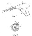
- FIG. 1 shows a fastener applier 100 and associated fasteners in an illustrative embodiment.
- the applier 100 includes a handle 1 and a shaft 2 extending distally from the handle 1.
- the shaft 2 houses a rotator 3 and a plurality of fasteners 4 on a mandrel 5.
- a trigger or other actuator 6 on the handle 1 may be operated by a user to cause the rotator 3 to rotate at least a distal most fastener 4 relative to the mandrel 5, thereby causing an internal thread of the fastener 4 to engage with threads on the mandrel 5 and drive the fastener 4 distally relative to the mandrel 5.
- Operation of the actuator 6 may also serve to move the mandrel 5 distally relative to the rotator 3 and/or the shaft 2, e.g., so that a pointed end on the mandrel 5 is exposed from the distal end of the shaft 2. Once the distalmost fastener 4 is deployed, the mandrel 5 may retract within the shaft 2.
- the rotator 3 may take any suitable form to rotate the fasteners 4 relative to the mandrel 5.
- the rotator 3 has a tubular shape with an approximately oval cross section, as can be seen in FIG. 2 .
- the flat surfaces 31 of the rotator 3 may engage with corresponding surfaces on the fasteners 4 , e.g., flat side surfaces on heads of the fasteners 4, yet still allow the fasteners 4 to move axially along the mandrel 5 relative to the rotator 3.
- the circular portions of the rotator 3 may be in close contact with the inner surface of the shaft 2, e.g., to help prevent the rotator 3 from wobbling in the shaft 2 during rotation. It should be understood, however, that the rotator 3 may have any suitable arrangement.
- the rotator 3 may have a hexagonal, square, star-shaped or other cross section so as to engage with corresponding surfaces on the fasteners 4.
- the rotator 3 may have one or more ribs, splines, tabs, grooves or other features that engage with the fasteners 4 to cause their rotation.
- the rotator 3 need not have a tube-like construction, and instead may engage with the fasteners in other ways.
- the rotator 3 may have one or more prongs that extend longitudinally through the shaft 2 and through corresponding holes or grooves in the fasteners 4. Rotation of the prongs about the mandrel 5 may rotate the fasteners 4 for deployment.
- the rotator 3 may include a gear that extends along one side of the shaft 2.
- the gear may partially extend into the inner space of the shaft 2 to contact the fasteners 4.
- Rotation of the gear may rotate the fasteners (which may have complementary gear teeth formed on their heads to engage with the gear) to deploy the fasteners as described above.
- the rotator 3 may only rotate the distalmost fastener 4 and trailing fasteners may be fed forward by other means, such as a spring.
- the mandrel 5 may only include a threaded portion near a distal end of the shaft. More proximal portions of the mandrel 5 may have a smooth cylindrical surface or other arrangement that does not engage with fasteners 4.
- FIGS. 3-5 show a fastener being deployed by the applier 100 in FIG. 1 .
- a user may position the distal end of the shaft 2 against a subject material, such as a mesh prosthetic 81 positioned on a muscle tissue 82.
- the mandrel 5 and the distalmost fastener 4 may be located within the shaft 2 (although in other embodiments, the mandrel 5 and/or the fastener 4 may be exposed).
- Actuation of the applier 100 may initially extend the mandrel 5 outside of the distal end of the shaft 2 so that the mandrel 5 penetrates the mesh 81 and/or tissue 82.
- the mandrel 5 has a sharpened tip to aid in puncturing the subject material, but other arrangements are possible, such as a gimlet feature, a conical tip, blunt end or other on the mandrel's distal end.
- the mandrel 5 may not penetrate the subject material, but rather may only press against the material or be positioned adjacent the material, e.g., in embodiments in which the mandrel 5 does not extend distally from the shaft 2.
- the mandrel 5 extends into the subject material without rotation, but in some embodiments, the mandrel 5 may rotate as it punctures the subject material, e.g., to aid in entry into the material.
- the rotator 3 may remain stationary so the fasteners 4, which are engaged with the threads on the mandrel 5, slide distally with the mandrel 5 relative to the rotator 3 as the mandrel 5 is extended.
- exposure of the mandrel 5 from the distal end of the shaft 2 may occur by having the distal end of the shaft 2 and/or the rotator 3 retract proximally, e.g., as the shaft's distal end is pressed against the material, in addition to, or instead of, having the mandrel 5 move distally.
- the rotator 3 may be rotated about the mandrel 5. This causes the fasteners 4 to rotate relative to the mandrel 5 (which remains rotationally stationary) and move distally on the mandrel threads. As the distal tip of the distalmost fastener 4 emerges from the shaft 2, the fastener 4 penetrates the mesh 81 and the tissue 82. In addition to the threaded engagement of the fastener 4 with the mandrel 5 forcing the fastener 4 to move distally as the rotator 3 rotates, the external thread on the fastener 4 may engage with the mesh 81 and tissue 82 and help to pull the fastener into the material.
- the fastener 4 With suitable rotation of the fastener 4, the fastener 4 is fully inserted into the material as shown in FIG. 5 .
- a proximal portion of the throughbore in the fasteners 4 does not engage with the threaded portion of the mandrel 5, e.g., only the distal portion of the throughbore is internally threaded - the proximal portion has a smooth cylindrical shape or other configuration that does not engage with the mandrel's threads.
- the fastener 4 may be disengaged from the mandrel 5, and the mandrel 5, rotator 3 and shaft 2 may be pulled away from the tack to deploy the fastener 4 from the applier 100.
- the mandrel 5 may be retracted into the shaft 2 to the position shown in FIG. 3 , ready to deploy a next fastener in the applier 100.
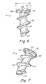
- FIGS. 6-10 show various views of a fastener 4 in an illustrative embodiment.
- FIG. 6 shows a side view of the fastener 4, which has a head 41, an external helical thread 42 and a barrel portion 43.
- the head 41 may have any suitable shape and/or size, and in this embodiment has a generally flat distal face near the thread 42 and a rounded proximal face.
- the external thread 42 may have a diameter d that is close in size to the head 41 in the view shown in FIG. 6 .
- the external thread 42 may make approximately 31 ⁇ 2 revolutions around the barrel portion 43, although in other embodiments, the thread 42 may make fewer or more revolutions.
- the external thread 42 may also taper down near the distal end of the barrel portion 43. This tapering may aid in the fastener's penetration into a subject material, such as a mesh 81.
- the thread 42 does not taper at the proximal end of the barrel portion 43, but instead maintains a relatively constant diameter to a point at which the thread 42 joins the head 41.
- the thread 42 may taper down, e.g., to having a zero crest height, at or before the head 41.
- Having the thread 42 extend to the head 41 may help allow the fastener 4 to be removed from a material, such as mesh 81, by simply rotating the fastener 4 in a reverse direction.
- a thread arrangement may permit the fastener 4 to be "overdriven” and pass through a mesh 81 or other material to an undesired depth.
- Having a gap between the proximal most end of the thread 42 and the head 41 may help stop the fastener insertion at a material surface, and may also cause some materials, such as a mesh 81, to be captured between the thread 42 and the head 41.
- the external thread 42 may be made, such as different thread pitches, a variable thread pitch, different thread face angles (leading and/or trailing faces), thread crest shapes (pointed, flat as shown, rounded, etc.), two or more threads, and so on.
- the external thread 42 may also have the distal most portion of the thread 42 extend forward of the barrel portion 43, e.g., forming a gimlet, hook or prong portion that may aid in leading the fastener 4 into a material.
- any suitable external thread 42 arrangement may be used in some aspects of the invention.
- the barrel portion may have an angled front face 431 or elliptical forward edge.
- the barrel portion 43 may have an angled distal end. If the barrel portion 43 has a cylindrical or conical form, the angled distal end may result in an elliptical forward edge being present on the barrel portion 43. This arrangement may aid in penetration of the fastener 4 in a material, e.g., because only a leading part of the distal end of the barrel portion 43 first penetrates the material, leading the way for the trailing part of the distal end.
- distal end of the tack may have a sharp leading edge to help penetrate material.
- FIGS. 7 and 8 show bottom and top perspective views of the fastener 4.
- the head 41 of the fastener 4 includes opposed, flat side surfaces 411 which engage with the flat surfaces 31 of the rotator 3.
- the thread 42 includes a flattened portion 421, which may contact the surfaces 31 of the rotator 3, e.g., to help stabilize the fastener 4 in the rotator 3.
- the flattened portion 421 may also help to maximize the crest height of the thread 42 while also maintaining the diameter d of the thread 42 to be less than the distance between the side surfaces 411 of the head 41, e.g., to enable the fastener 4 to fit within the rotator 3.
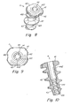
- the head 41 may also include curved depressions 412 in opposed sides of the head 41.
- These curved depressions 412 may aid in properly aligning a plurality of fasteners 4 when assembling the fasteners 4 for loading into a system 100.
- the depressions 412 may have the same size and/or shape, or may be different to help ensure that all fasteners 4 loaded into a system are similarly aligned. Alignment of the fasteners 4 may be important, for example, when the fasteners 4 have a non-symmetrical shape, e.g., include an angled distal face like that shown in FIG. 6 .
- the depressions 412 may also serve to reduce the contact area between the fasteners 4 and the rotator 3, thereby potentially reducing friction that may resist sliding movement of the fasteners 4 in the rotator 3.
- FIG. 9 shows a top view of the fastener 4 along with the curved depressions 412 and the side surfaces 411.
- the fasteners may have a throughbore 44 extending through the barrel portion 43 and the head 41.
- the throughbore 44 may extend along a longitudinal axis of the barrel portion 43, and as can be seen in FIG. 9 , provide a pathway through the fastener 4.
- a portion of the throughbore 44 may have an internally threaded portion 441, e.g., at a distal portion of the throughbore 44 as shown in a cross sectional view of the fastener in FIG. 10 .
- a proximal portion 442 of the throughbore may have a larger diameter than the threaded portion 441, e.g., so that the proximal portion 442 does not engage with the mandrel 5.
- the proximal portion 442 may have any shape or size, e.g., may have a smooth cylindrically shaped bore.
- the throughbore 44 By arranging the throughbore 44 so that only a distal portion of the fastener 4 engages with the mandrel 5, the fastener 4 may be more easily disengaged from the mandrel 5 during deployment.
- the throughbore 44 be threaded along its entire length, or may be threaded only at the proximal end. In this case, the mandrel 5 may be unthreaded at its distal end, if desired.
- a pitch of the internal threaded portion 441 may be the same as, longer, or shorter than a pitch of the external thread 42.
- the thread pitch of the internally threaded portion 441 is shorter than the thread pitch of the external thread 42, e.g., to help aid in disengaging the fasteners 4 from the mandrel 5 during deployment. That is, the longer thread pitch of the external thread 42 may help to pull the fastener 4 from the mandrel 5 as the fastener 4 is driven into a material.
- the fastener may be made of any suitable biocompatible material, such as an absorbable material (e.g., PLA or other), a non-absorbable metal or plastic (e.g., titanium), or any other material or combination of materials. Further, the fasteners 4 may be made of any suitable size, e.g., about 1 ⁇ 4 inch long and about 1/8 inch in diameter with a throughbore diameter of about 1/32 inch.
- an absorbable material e.g., PLA or other
- a non-absorbable metal or plastic e.g., titanium
- the fasteners 4 may be made of any suitable size, e.g., about 1 ⁇ 4 inch long and about 1/8 inch in diameter with a throughbore diameter of about 1/32 inch.
- the applier 100 may deploy fasteners 4 using a manually operated mechanism, a motorized mechanism, or a combination of manual and motorized.
- FIGS. 11 and 12 show left and right side views, respectively, of a manually-operated mechanism for the applier 100 of FIG. 1 .
- the handle 1 includes a trigger 6 that has two operable trigger levers 61 and 62 that both pivot about a trigger pivot 63.
- the outer trigger lever 61 is exposed and is gripped by a user, whereas the inner trigger lever 62 is housed inside of the outer trigger lever 61.
- Both trigger levers 61 and 62 are urged to a starting position shown in FIG. 11 by a spring 64 or other suitable resilient member.
- the inner trigger lever 62 includes a rotator drive rack 622 that engages with a rotator drive pinion 14 (see FIG. 12 ). Movement of the inner trigger lever 62 therefore causes rotation of the rotator drive pinion 14 and an associated bevel gear 141, which is engaged with a complementary bevel gear of a clutch 15.
- rotation of the rotator drive pinion 14 causes the bevel gear 141 to rotate the clutch 15 (e.g., in a clockwise direction looking from the handle 1 down the shaft 2).
- the clutch 15 is engaged with the rotator 3, and thus rotation of the clutch 15 in the clockwise direction causes the rotator 3 to rotate clockwise as well.
- Continued depression of the trigger levers 61 and 62 rotates the rotator 3 and causes a fastener 4 to be deployed as described above.
- a pawl 16 is arranged to engage with the mandrel drive rack 611 so that once fastener rotation begins (i.e., once the outer trigger 61 contacts the inner trigger 62 and the clutch 15 rotates the rotator 3), the trigger levers 61 and 62 cannot return to the starting position of FIG. 11 until the trigger levers 61 and 62 are completely depressed.
- the pawl 16 may clear the mandrel drive rack 611, allowing the mandrel drive rack 611 and trigger levers 61 and 62 to return to the starting position. Return movement of the trigger levers 61 and 62 may cause the mandrel drive pinion 11 and the rotator drive pinion 14 to be backdriven.
- Deployment of a distal most fastener 4 may occur during the stroke of the trigger levers 61 and 62, i.e., before the trigger levers 61 and 62 are completely depressed and the pawl 16 clears the mandrel drive rack 611.
- This arrangement may help ensure that the fastener 4 is disengaged from the mandrel 5 before rotation of the rotator 3 stops and the mandrel 5 is retracted.
- the fastener 4 may be arranged to disengage from the mandrel 5 upon three revolutions of the rotator 3.
- the rotator 3 may be arranged to rotate 31 ⁇ 2 revolutions before stopping.
- the pawl 16 may be arranged to require further depression of the trigger levers 61 and 62 before the pawl 16 clears the rack 611. During this motion of the trigger levers 61 and 62, other functions may be performed, such as actuating a counter to indicate that a fastener has been deployed.
- a display of fasteners deployed and/or fasteners remaining may be provided on the handle 1, e.g., on an LCD or LED display.
Landscapes
- Health & Medical Sciences (AREA)
- Surgery (AREA)
- Life Sciences & Earth Sciences (AREA)
- Engineering & Computer Science (AREA)
- Veterinary Medicine (AREA)
- Animal Behavior & Ethology (AREA)
- Heart & Thoracic Surgery (AREA)
- Public Health (AREA)
- General Health & Medical Sciences (AREA)
- Molecular Biology (AREA)
- Biomedical Technology (AREA)
- Medical Informatics (AREA)
- Nuclear Medicine, Radiotherapy & Molecular Imaging (AREA)
- Mechanical Engineering (AREA)
- Vascular Medicine (AREA)
- Epidemiology (AREA)
- Surgical Instruments (AREA)
- Prostheses (AREA)
Applications Claiming Priority (4)
| Application Number | Priority Date | Filing Date | Title |
|---|---|---|---|
| US11/408,399 US7862573B2 (en) | 2006-04-21 | 2006-04-21 | Method and apparatus for surgical fastening |
| EP10179974.0A EP2258279B1 (fr) | 2006-04-21 | 2007-04-18 | Appareil de fixation chirurgicale |
| EP07755715A EP2012676B1 (fr) | 2006-04-21 | 2007-04-18 | Procédé et appareil de fixation chirurgicale |
| PCT/US2007/009542 WO2007123978A2 (fr) | 2006-04-21 | 2007-04-18 | Procédé et appareil de fixation chirurgicale |
Related Parent Applications (4)
| Application Number | Title | Priority Date | Filing Date |
|---|---|---|---|
| EP07755715A Division EP2012676B1 (fr) | 2006-04-21 | 2007-04-18 | Procédé et appareil de fixation chirurgicale |
| EP07755715.5 Division | 2007-04-18 | ||
| EP10179974.0A Division EP2258279B1 (fr) | 2006-04-21 | 2007-04-18 | Appareil de fixation chirurgicale |
| EP10179974.0 Division | 2010-09-27 |
Publications (2)
| Publication Number | Publication Date |
|---|---|
| EP2361559A1 true EP2361559A1 (fr) | 2011-08-31 |
| EP2361559B1 EP2361559B1 (fr) | 2018-09-26 |
Family
ID=38548098
Family Applications (3)
| Application Number | Title | Priority Date | Filing Date |
|---|---|---|---|
| EP07755715A Active EP2012676B1 (fr) | 2006-04-21 | 2007-04-18 | Procédé et appareil de fixation chirurgicale |
| EP11167098.0A Active EP2361559B1 (fr) | 2006-04-21 | 2007-04-18 | Appareil de fixation chirurgicale |
| EP10179974.0A Active EP2258279B1 (fr) | 2006-04-21 | 2007-04-18 | Appareil de fixation chirurgicale |
Family Applications Before (1)
| Application Number | Title | Priority Date | Filing Date |
|---|---|---|---|
| EP07755715A Active EP2012676B1 (fr) | 2006-04-21 | 2007-04-18 | Procédé et appareil de fixation chirurgicale |
Family Applications After (1)
| Application Number | Title | Priority Date | Filing Date |
|---|---|---|---|
| EP10179974.0A Active EP2258279B1 (fr) | 2006-04-21 | 2007-04-18 | Appareil de fixation chirurgicale |
Country Status (9)
| Country | Link |
|---|---|
| US (2) | US7862573B2 (fr) |
| EP (3) | EP2012676B1 (fr) |
| JP (2) | JP5268887B2 (fr) |
| AT (1) | ATE486528T1 (fr) |
| AU (1) | AU2007240814B2 (fr) |
| CA (2) | CA2862649C (fr) |
| DE (1) | DE602007010273D1 (fr) |
| ES (3) | ES2428417T3 (fr) |
| WO (1) | WO2007123978A2 (fr) |
Cited By (1)
| Publication number | Priority date | Publication date | Assignee | Title |
|---|---|---|---|---|
| US10363039B2 (en) | 2015-11-20 | 2019-07-30 | Covidien Lp | Surgical fastener appliers |
Families Citing this family (111)
| Publication number | Priority date | Publication date | Assignee | Title |
|---|---|---|---|---|
| EP1511427B1 (fr) * | 2002-06-11 | 2007-02-14 | Tyco Healthcare Group Lp | Clous de tricots à mailles pour hernies |
| EP2298184A1 (fr) | 2003-06-13 | 2011-03-23 | Tyco Healthcare Group LP | Raccord a éléments multiples pour instrument chirurgical et vis résorbable |
| US7960935B2 (en) | 2003-07-08 | 2011-06-14 | The Board Of Regents Of The University Of Nebraska | Robotic devices with agent delivery components and related methods |
| US10478179B2 (en) | 2004-04-27 | 2019-11-19 | Covidien Lp | Absorbable fastener for hernia mesh fixation |
| CA2575282A1 (fr) * | 2004-07-26 | 2006-02-02 | Global Engineered Fasteners Pty Ltd | Fixation de composants sur des materiaux composites |
| US8100946B2 (en) | 2005-11-21 | 2012-01-24 | Synthes Usa, Llc | Polyaxial bone anchors with increased angulation |
| CA3068216C (fr) | 2006-06-22 | 2023-03-07 | Board Of Regents Of The University Of Nebraska | Dispositifs robotiques pouvant etre couples magnetiquement et procedes associes |
| US9579088B2 (en) | 2007-02-20 | 2017-02-28 | Board Of Regents Of The University Of Nebraska | Methods, systems, and devices for surgical visualization and device manipulation |
| US8679096B2 (en) | 2007-06-21 | 2014-03-25 | Board Of Regents Of The University Of Nebraska | Multifunctional operational component for robotic devices |
| WO2008010948A2 (fr) * | 2006-07-18 | 2008-01-24 | Davol Inc. | Procédé et appareil de vissage chirurgical |
| JP4702216B2 (ja) * | 2006-08-03 | 2011-06-15 | オムロンヘルスケア株式会社 | 電子血圧計およびその制御方法 |
| JP5591696B2 (ja) | 2007-07-12 | 2014-09-17 | ボード オブ リージェンツ オブ ザ ユニバーシティ オブ ネブラスカ | 生検要素、アーム装置、および医療装置 |
| PL2170192T3 (pl) | 2007-07-20 | 2011-07-29 | Synthes Gmbh | Wieloosiowy przyrząd do stabilizacji kości |
| US9439681B2 (en) | 2007-07-20 | 2016-09-13 | DePuy Synthes Products, Inc. | Polyaxial bone fixation element |
| WO2009023851A1 (fr) | 2007-08-15 | 2009-02-19 | Board Of Regents Of The University Of Nebraska | Dispositifs médicaux modulaires et coopératifs et systèmes et procédés apparentés |
| US20090076536A1 (en) | 2007-08-15 | 2009-03-19 | Board Of Regents Of The University Of Nebraska | Medical inflation, attachment, and delivery devices and related methods |
| US8597336B2 (en) * | 2007-12-28 | 2013-12-03 | Howmedica Osteonics Corp. | Apparatus for discrete tissue anchoring for soft tissue repair and method of use |
| US8257407B2 (en) * | 2008-04-23 | 2012-09-04 | Aryan Henry E | Bone plate system and method |
| WO2010028287A2 (fr) | 2008-09-05 | 2010-03-11 | Synthes Usa, Llc | Ensemble fixation osseuse |
| US8777990B2 (en) | 2008-09-08 | 2014-07-15 | Howmedica Osteonics Corp. | Knotless suture anchor for soft tissue repair and method of use |
| JP5815407B2 (ja) | 2008-09-12 | 2015-11-17 | ジンテス ゲゼルシャフト ミット ベシュレンクテル ハフツング | 脊椎安定化及び誘導固定システム |
| WO2010037098A1 (fr) | 2008-09-29 | 2010-04-01 | Synthes Usa, Llc | Vis polyaxiale à chargement par le bas et ensemble tige |
| EP2376005B1 (fr) | 2008-11-03 | 2016-05-18 | Synthes GmbH | Ensemble fixation osseuse plane |
| US9451942B2 (en) * | 2008-11-12 | 2016-09-27 | Howmedica Osteonics Corp. | Insertion tool for knotless suture anchor for soft tissue repair and method of use |
| EP2375995A1 (fr) * | 2008-12-15 | 2011-10-19 | Smith & Nephew, Inc. | Ancre composite |
| FR2941144B1 (fr) * | 2009-01-22 | 2012-04-27 | Sofradim Production | Agrafeuse chirurgicale pour le prepositionnement et la fixation de prothese en textile, methode de chargement de celle-ci et agrafe chirurgicale auto-agrippante |
| CN102368967B (zh) | 2009-04-15 | 2016-03-02 | 斯恩蒂斯有限公司 | 用于脊椎结构的修正连接器 |
| WO2010148231A1 (fr) | 2009-06-17 | 2010-12-23 | Synthes Usa, Llc | Connecteur de révision pour constructions rachidiennes |
| WO2011075693A1 (fr) | 2009-12-17 | 2011-06-23 | Board Of Regents Of The University Of Nebraska | Dispositifs médicaux modulaires et utilisables en interaction et systèmes et procédés afférents |
| AU2015202455B2 (en) * | 2009-12-30 | 2017-10-19 | Boston Scientific Scimed, Inc. | Implantable sling systems and methods |
| WO2011082330A1 (fr) | 2009-12-30 | 2011-07-07 | Ams Research Corporation | Systèmes d'écharpe implantable et procédés associés |
| EP2528518B1 (fr) * | 2010-01-26 | 2017-12-13 | Artack Medical (2013) Ltd. | Instrument médical articulé |
| US8683895B2 (en) * | 2010-02-23 | 2014-04-01 | Kensey Nash Corporation | Single revolution snap action drive for surgical fasteners |
| EP2600758A1 (fr) * | 2010-08-06 | 2013-06-12 | Board of Regents of the University of Nebraska | Procédés et systèmes de manipulation ou d'administration de matériaux pour une chirurgie des orifices naturels |
| JP5989759B2 (ja) * | 2011-03-22 | 2016-09-07 | スミス アンド ネフュー インコーポレーテッド | 係留システム、及び当該係留システムと共に利用するための送り装置 |
| EP3714821A1 (fr) | 2011-06-10 | 2020-09-30 | Board of Regents of the University of Nebraska | Effecteur d'extrémité chirurgicale |
| FR2977471B1 (fr) | 2011-07-07 | 2013-07-05 | Aspide Medical | Dispositif comprenant une pluralite d'implants pour la fixation de materiel prothetique |
| EP2732344B1 (fr) | 2011-07-11 | 2019-06-05 | Board of Regents of the University of Nebraska | Système chirurgical robotisé |
| US9610109B2 (en) * | 2011-08-16 | 2017-04-04 | Howmedica Osteonics Corp. | Wedge shaped fracture fixation devices and methods for using the same |
| EP2760345B1 (fr) | 2011-09-26 | 2016-12-07 | Artack Medical (2013) Ltd. | Dispositif de fixation chirurgicale |
| US8535339B2 (en) | 2011-12-18 | 2013-09-17 | Via Surgical Ltd. | Apparatus and method for suturing |
| JP6377530B2 (ja) | 2012-01-10 | 2018-08-22 | ボード オブ リージェンツ オブ ザ ユニバーシティ オブ ネブラスカ | 外科的挿入装置 |
| EP2844181B1 (fr) | 2012-05-01 | 2021-03-10 | Board of Regents of the University of Nebraska | Dispositif robotique à site unique et systèmes associés |
| US9888913B2 (en) | 2012-05-31 | 2018-02-13 | Via Surgical Ltd. | Variable depth surgical fixation |
| ES2733939T3 (es) * | 2012-05-31 | 2019-12-03 | Via Surgical Ltd | Fijación quirúrgica de profundidad variable |
| US9010214B2 (en) | 2012-06-22 | 2015-04-21 | Board Of Regents Of The University Of Nebraska | Local control robotic surgical devices and related methods |
| US9770305B2 (en) | 2012-08-08 | 2017-09-26 | Board Of Regents Of The University Of Nebraska | Robotic surgical devices, systems, and related methods |
| EP2882331A4 (fr) | 2012-08-08 | 2016-03-23 | Univ Nebraska | Systèmes et dispositifs chirurgicaux robotiques, et procédés associés |
| US9198657B2 (en) | 2012-09-13 | 2015-12-01 | Basil Anthony Kocur | Anchor unit implant |
| US9351733B2 (en) | 2013-01-18 | 2016-05-31 | Covidien Lp | Surgical fastener applier |
| CN105188562B (zh) | 2013-03-06 | 2019-02-26 | 史密夫和内修有限公司 | 微型锚定器 |
| US9993245B2 (en) | 2013-03-11 | 2018-06-12 | Via Surgical Ltd. | Surgical tacker with quantity indicator |
| US9358010B2 (en) | 2013-03-12 | 2016-06-07 | Covidien Lp | Flex cable and spring-loaded tube for tacking device |
| US9474530B2 (en) * | 2013-03-14 | 2016-10-25 | C.R. Bard, Inc. | Handling of fasteners within a surgical instrument |
| US9867620B2 (en) | 2013-03-14 | 2018-01-16 | Covidien Lp | Articulation joint for apparatus for endoscopic procedures |
| WO2014152418A1 (fr) | 2013-03-14 | 2014-09-25 | Board Of Regents Of The University Of Nebraska | Procédés, systèmes et dispositifs associés à des systèmes chirurgicaux de commande de force |
| US9427230B2 (en) | 2013-03-14 | 2016-08-30 | C.R. Bard, Inc. | Handling of fasteners within a surgical instrument |
| US9743987B2 (en) | 2013-03-14 | 2017-08-29 | Board Of Regents Of The University Of Nebraska | Methods, systems, and devices relating to robotic surgical devices, end effectors, and controllers |
| CA2906772C (fr) | 2013-03-15 | 2021-09-21 | Board Of Regents Of The University Of Nebraska | Dispositifs chirurgicaux robotiques, systemes et procedes apparentes |
| US9655621B2 (en) | 2013-03-15 | 2017-05-23 | Covidien Lp | Surgical instrument for dispensing tacks and solution |
| US9668730B2 (en) | 2013-06-28 | 2017-06-06 | Covidien Lp | Articulating apparatus for endoscopic procedures with timing system |
| US9358004B2 (en) | 2013-06-28 | 2016-06-07 | Covidien Lp | Articulating apparatus for endoscopic procedures |
| US9351728B2 (en) | 2013-06-28 | 2016-05-31 | Covidien Lp | Articulating apparatus for endoscopic procedures |
| US10085746B2 (en) | 2013-06-28 | 2018-10-02 | Covidien Lp | Surgical instrument including rotating end effector and rotation-limiting structure |
| CA2918531A1 (fr) | 2013-07-17 | 2015-01-22 | Board Of Regents Of The University Of Nebraska | Dispositifs chirurgicaux robotiques, systemes et procedes apparentes |
| US20150032130A1 (en) | 2013-07-24 | 2015-01-29 | Covidien Lp | Expanding absorbable tack |
| US9526498B2 (en) | 2013-09-17 | 2016-12-27 | Covidien Lp | Surgical device with a trigger lockout mechanism device |
| US9445814B2 (en) | 2013-11-08 | 2016-09-20 | C.R. Bard, Inc. | Surgical fastener |
| US10285697B2 (en) | 2013-11-08 | 2019-05-14 | C.R. Bard, Inc. | Methods and apparatus for surgical fastening |
| US9615830B2 (en) | 2013-11-08 | 2017-04-11 | C.R. Bard, Inc. | Surgical fastener |
| US10368870B2 (en) | 2013-11-08 | 2019-08-06 | C.R. Bard, Inc. | Surgical fastener |
| US9675353B2 (en) * | 2013-11-08 | 2017-06-13 | C.R. Bard, Inc. | Surgical fasteners and associated deployment devices |
| ES2671426T3 (es) * | 2014-02-06 | 2018-06-06 | IGNITE-concepts GmbH | Conjunto de tornillo para hueso |
| US20150272584A1 (en) * | 2014-03-31 | 2015-10-01 | Coloplast A/S | Adapter attachable to a shaft of an anchor delivery tool |
| US10335146B2 (en) | 2014-04-02 | 2019-07-02 | Coviden Lp | Surgical fastener applying apparatus, kits and methods for endoscopic procedures |
| CA2961213A1 (fr) | 2014-09-12 | 2016-03-17 | Board Of Regents Of The University Of Nebraska | Effecteurs d'extremite a liberation rapide et systemes et procedes associes |
| EP3217890B1 (fr) | 2014-11-11 | 2020-04-08 | Board of Regents of the University of Nebraska | Dispositif robotisé à modèle d'articulation compacte |
| WO2016090018A1 (fr) | 2014-12-02 | 2016-06-09 | Akp Consulting | Dispositifs de compression active, procédés d'assemblage et procédés d'utilisation |
| US11090097B2 (en) | 2015-03-17 | 2021-08-17 | Covidien Lp | Connecting end effectors to surgical devices |
| WO2016170423A1 (fr) | 2015-04-23 | 2016-10-27 | Via Surgical Ltd. | Mécanisme de mise en place et de verrouillage d'élément de fixation chirurgical |
| CA2994823A1 (fr) | 2015-08-03 | 2017-02-09 | Board Of Regents Of The University Of Nebraska | Systemes de dispositifs chirurgicaux robotises et procedes apparentes |
| CN105496482B (zh) * | 2016-01-25 | 2018-06-15 | 北京天助畅运医疗技术股份有限公司 | 可吸收钉以及含有可吸收钉的软组织固定装置 |
| US10702264B2 (en) | 2016-01-25 | 2020-07-07 | TransEasy Medical Tech.Co., Ltd | Fixing device for soft tissue |
| CN115054358A (zh) | 2016-02-26 | 2022-09-16 | 艾缇沃托公司 | 主动压缩装置、组装方法和使用方法 |
| US11224467B2 (en) | 2016-02-26 | 2022-01-18 | Activortho, Inc. | Active compression apparatus, methods of assembly and methods of use |
| KR102303576B1 (ko) | 2016-04-21 | 2021-09-23 | 어플라이드 메디컬 리소시스 코포레이션 | 복강경 클립 어플라이어 |
| JP7176757B2 (ja) | 2016-05-18 | 2022-11-22 | バーチャル インシジョン コーポレイション | ロボット手術装置、システム及び関連する方法 |
| CA3034671A1 (fr) | 2016-08-25 | 2018-03-01 | Shane Farritor | Raccord d'outil a liberation rapide ainsi que systemes et procedes associes |
| EP3507065A4 (fr) | 2016-08-30 | 2020-04-29 | Board of Regents of the University of Nebraska | Dispositif robotique ayant une conception d'articulation compacte et un degré de liberté supplémentaire, et systèmes et procédés associés |
| US10743859B2 (en) | 2016-10-21 | 2020-08-18 | Covidien Lp | Surgical end effectors |
| US10617409B2 (en) | 2016-10-21 | 2020-04-14 | Covidien Lp | Surgical end effectors |
| US11298123B2 (en) | 2016-10-21 | 2022-04-12 | Covidien Lp | Surgical end effectors |
| CN115337111A (zh) | 2016-11-22 | 2022-11-15 | 内布拉斯加大学董事会 | 改进的粗定位装置及相关系统和方法 |
| EP3548773A4 (fr) | 2016-11-29 | 2020-08-05 | Virtual Incision Corporation | Dispositif de commande d'utilisateur à détection de présence d'utilisateur et systèmes et procédés associés |
| WO2018112199A1 (fr) | 2016-12-14 | 2018-06-21 | Virtual Incision Corporation | Dispositif de fixation libérable destiné à être accouplé à des dispositifs médicaux et systèmes et procédés associés |
| US10888309B2 (en) | 2017-01-31 | 2021-01-12 | Covidien Lp | Surgical fastener devices with geometric tubes |
| EP3687370A4 (fr) | 2017-09-27 | 2021-06-30 | Virtual Incision Corporation | Dispositifs chirurgicaux robotisés avec technologie de caméra de suivi et systèmes et procédés apparentés |
| CN117140580A (zh) | 2018-01-05 | 2023-12-01 | 内布拉斯加大学董事会 | 具有紧凑型关节设计的单臂机器人装置及相关系统和方法 |
| US10932776B2 (en) | 2018-01-10 | 2021-03-02 | C.R. Bard, Inc. | Surgical fasteners for articulating surgical instruments |
| US11298126B2 (en) | 2018-05-02 | 2022-04-12 | Covidien Lp | Shipping wedge for end effector installation onto surgical devices |
| US11116500B2 (en) | 2018-06-28 | 2021-09-14 | Covidien Lp | Surgical fastener applying device, kits and methods for endoscopic procedures |
| US11648000B2 (en) | 2018-07-30 | 2023-05-16 | Braunvest Llc | Vertebral probes and related surgical methods |
| US11903658B2 (en) | 2019-01-07 | 2024-02-20 | Virtual Incision Corporation | Robotically assisted surgical system and related devices and methods |
| US11154337B2 (en) | 2019-02-26 | 2021-10-26 | Medos Iniernational Sarl | Spinal screw handling |
| US11246636B2 (en) | 2019-04-26 | 2022-02-15 | Braunvest Llc | Systems, methods, and apparatus for spinal deformity correction |
| US11523817B2 (en) | 2019-06-27 | 2022-12-13 | Covidien Lp | Endoluminal pursestring device |
| CN110916735B (zh) * | 2019-11-26 | 2021-09-03 | 杭州电子科技大学 | 一种可降解生物活性螺钉及其制造方法 |
| USD944984S1 (en) | 2019-12-19 | 2022-03-01 | Covidien Lp | Tubular positioning guide |
| US11197675B2 (en) | 2019-12-19 | 2021-12-14 | Covidien Lp | Positioning guide for surgical instruments and surgical instrument systems |
| USD944985S1 (en) | 2019-12-19 | 2022-03-01 | Covidien Lp | Positioning guide cuff |
| CN113017733A (zh) * | 2021-03-30 | 2021-06-25 | 苏州奥芮济医疗科技有限公司 | 一种医疗锚钉及其加工工艺 |
Citations (9)
| Publication number | Priority date | Publication date | Assignee | Title |
|---|---|---|---|---|
| US5129906A (en) * | 1989-09-08 | 1992-07-14 | Linvatec Corporation | Bioabsorbable tack for joining bodily tissue and in vivo method and apparatus for deploying same |
| US20020032466A1 (en) * | 1996-08-05 | 2002-03-14 | Arthrex, Inc. | Headed bioabsorbable tissue anchor |
| US20040049227A1 (en) | 1998-11-18 | 2004-03-11 | Jervis James E. | Helical fastener and applicator for surgical procedures |
| US20040147928A1 (en) * | 2002-10-30 | 2004-07-29 | Landry Michael E. | Spinal stabilization system using flexible members |
| US20040204723A1 (en) | 2001-10-23 | 2004-10-14 | Helmut Kayan | Surgical fasteners |
| WO2005007212A2 (fr) * | 2003-07-10 | 2005-01-27 | Friedrich-Baur-Gmbh | Systeme de liberation de substance active a ajustage individuel |
| US20050171562A1 (en) | 2002-06-11 | 2005-08-04 | Criscuolo Christopher J. | Hernia mesh tacks |
| CA2145449C (fr) * | 1994-03-29 | 2005-09-13 | Andreas C. Stahelin | Vis en materiau biodegradable pour la chirurgie osseuse et tournevis correspondant |
| US20050267478A1 (en) * | 2003-06-13 | 2005-12-01 | Corradi Ralph R | Surgical fastener with predetermined resorption rate |
Family Cites Families (90)
| Publication number | Priority date | Publication date | Assignee | Title |
|---|---|---|---|---|
| US1815594A (en) * | 1929-10-01 | 1931-07-21 | Keller Mechanical Eng | Screw driver screw holding device |
| US2033039A (en) * | 1935-05-22 | 1936-03-03 | Arthur A Limpert | Double point rotary pin |
| US3258042A (en) * | 1964-08-24 | 1966-06-28 | Herbert C Brauchla | Screw strip driving gun |
| US3545444A (en) * | 1967-10-02 | 1970-12-08 | United States Surgical Corp | Wire suture wrapping instrument |
| US3579793A (en) * | 1968-09-24 | 1971-05-25 | Microdot Inc | Power tool for thread inserts |
| US3515194A (en) * | 1969-03-17 | 1970-06-02 | Acme Staple Co Inc | Threaded staple |
| US3737579A (en) * | 1971-04-19 | 1973-06-05 | Medtronic Inc | Body tissue electrode and device for screwing the electrode into body tissue |
| US3971421A (en) * | 1974-02-26 | 1976-07-27 | Triad Fastener Corporation | Air-powered, self-feeding screw driving tool |
| US4154241A (en) * | 1977-07-29 | 1979-05-15 | Rudie Peter S | Anastomosis clamp |
| US4146321A (en) * | 1977-08-08 | 1979-03-27 | Melillo Dominic S | Reversible film cartridge and camera |
| US4809695A (en) * | 1981-10-21 | 1989-03-07 | Owen M. Gwathmey | Suturing assembly and method |
| US4496090A (en) * | 1982-03-10 | 1985-01-29 | Crevier Paul H | Surgical stapler |
| US4449283A (en) * | 1982-06-16 | 1984-05-22 | Microdot Inc. | Semi-automatic insert tool |
| DE3327751A1 (de) * | 1982-08-06 | 1984-02-09 | Avdel Ltd., Welwyn Garden City, Hertfordshire | Verankerungsmutter-befestigungsvorrichtung |
| US4595007A (en) * | 1983-03-14 | 1986-06-17 | Ethicon, Inc. | Split ring type tissue fastener |
| US4595009A (en) * | 1984-02-06 | 1986-06-17 | Medtronic, Inc. | Protection circuit for implantable cardioverter |
| US4873976A (en) * | 1984-02-28 | 1989-10-17 | Schreiber Saul N | Surgical fasteners and method |
| US4667545A (en) * | 1985-06-03 | 1987-05-26 | Gould Jr Frederick H | Screw gun automatic feed |
| GB8514608D0 (en) * | 1985-06-10 | 1985-07-10 | Crosfield Electronics Ltd | Colour modification in image reproduction systems |
| JPS628193A (ja) * | 1985-07-04 | 1987-01-16 | インタ−ナショナル ビジネス マシ−ンズ コ−ポレ−ション | カラー画像表示装置 |
| EP0209685A3 (fr) * | 1985-07-12 | 1988-11-09 | Fischerwerke Arthur Fischer GmbH & Co. KG | Elément de fixation pour ostéosynthèse |
| US4662555A (en) * | 1986-03-11 | 1987-05-05 | Edward Weck & Company, Inc. | Surgical stapler |
| US4924865A (en) * | 1986-05-20 | 1990-05-15 | Concept, Inc. | Repair tack for bodily tissue |
| US4878794A (en) * | 1988-03-15 | 1989-11-07 | John W. Hall, Jr. | Collated screw fasteners |
| DE3811345C1 (fr) | 1988-04-02 | 1989-09-07 | Aesculap Ag, 7200 Tuttlingen, De | |
| CA1320005C (fr) * | 1988-06-16 | 1993-07-06 | Kotaro Harigane | Dispositif de montage d'element electronique |
| CH681273A5 (fr) | 1988-12-16 | 1993-02-26 | Sulzer Ag | |
| US5053047A (en) * | 1989-05-16 | 1991-10-01 | Inbae Yoon | Suture devices particularly useful in endoscopic surgery and methods of suturing |
| US5161725A (en) * | 1990-02-13 | 1992-11-10 | Ethicon, Inc. | Rotating head skin stapler |
| US5035692A (en) * | 1990-02-13 | 1991-07-30 | Nicholas Herbert | Hemostasis clip applicator |
| US5127413A (en) * | 1990-08-09 | 1992-07-07 | Ebert Edward A | Sinous suture |
| US5098238A (en) * | 1990-12-20 | 1992-03-24 | Hi-Shear Corporation | Fastener with internal threaded installation means |
| US5498265A (en) * | 1991-03-05 | 1996-03-12 | Howmedica Inc. | Screw and driver |
| CA2062012C (fr) | 1991-03-05 | 2003-04-29 | Randall D. Ross | Vis bioabsorbable a tete a interference pour immobilisation de fracture |
| US5246156A (en) * | 1991-09-12 | 1993-09-21 | Ethicon, Inc. | Multiple fire endoscopic stapling mechanism |
| US5257713A (en) * | 1991-05-07 | 1993-11-02 | United States Surgical Corporation | Surgical fastening device |
| US5356064A (en) * | 1991-10-18 | 1994-10-18 | United States Surgical Corporation | Apparatus and method for applying surgical staples to attach an object to body tissue |
| US5289963A (en) * | 1991-10-18 | 1994-03-01 | United States Surgical Corporation | Apparatus and method for applying surgical staples to attach an object to body tissue |
| US5258000A (en) * | 1991-11-25 | 1993-11-02 | Cook Incorporated | Tissue aperture repair device |
| US5211647A (en) * | 1992-02-19 | 1993-05-18 | Arthrex Inc. | Interference screw and cannulated sheath for endosteal fixation of ligaments |
| US5163343A (en) * | 1992-02-21 | 1992-11-17 | Gish Donald A | System for fastening plies of fabric |
| US5192288A (en) * | 1992-05-26 | 1993-03-09 | Origin Medsystems, Inc. | Surgical clip applier |
| US5312415A (en) * | 1992-09-22 | 1994-05-17 | Target Therapeutics, Inc. | Assembly for placement of embolic coils using frictional placement |
| NZ248798A (en) * | 1992-09-29 | 1995-11-27 | Lysaght Australia Ltd | Impact drivable fastener having a tapered helical fluted section with ribs and flutes increasing from zero value adjacent to tip end towards head end |
| US5381943A (en) * | 1992-10-09 | 1995-01-17 | Ethicon, Inc. | Endoscopic surgical stapling instrument with pivotable and rotatable staple cartridge |
| US5601224A (en) * | 1992-10-09 | 1997-02-11 | Ethicon, Inc. | Surgical instrument |
| DE4304353A1 (de) * | 1992-10-24 | 1994-04-28 | Helmut Dipl Ing Wurster | Endoskopisches Nähgerät |
| US5354299A (en) | 1992-12-07 | 1994-10-11 | Linvatec Corporation | Method of revising a screw in a tunnel |
| US6030162A (en) * | 1998-12-18 | 2000-02-29 | Acumed, Inc. | Axial tension screw |
| US5356424A (en) * | 1993-02-05 | 1994-10-18 | American Cyanamid Co. | Laparoscopic suturing device |
| WO1994020040A1 (fr) | 1993-03-01 | 1994-09-15 | Synvasive Technology, Inc. | Dispositif de fixation et de compression possedant un pas de vis non homogene |
| US5354292A (en) * | 1993-03-02 | 1994-10-11 | Braeuer Harry L | Surgical mesh introduce with bone screw applicator for the repair of an inguinal hernia |
| US5352229A (en) * | 1993-05-12 | 1994-10-04 | Marlowe Goble E | Arbor press staple and washer and method for its use |
| US5632748A (en) * | 1993-06-14 | 1997-05-27 | Linvatec Corporation | Endosteal anchoring device for urging a ligament against a bone surface |
| US5411522A (en) * | 1993-08-25 | 1995-05-02 | Linvatec Corporation | Unitary anchor for soft tissue fixation |
| AU1011595A (en) | 1994-01-13 | 1995-07-20 | Ethicon Inc. | Spiral surgical tack |
| US5425490A (en) * | 1994-01-18 | 1995-06-20 | Goble; E. Marlowe | Instrument with dual holding feature |
| US6001101A (en) | 1994-07-05 | 1999-12-14 | Depuy France | Screw device with threaded head for permitting the coaptation of two bone fragments |
| US5582616A (en) * | 1994-08-05 | 1996-12-10 | Origin Medsystems, Inc. | Surgical helical fastener with applicator |
| JPH0852156A (ja) * | 1994-08-15 | 1996-02-27 | Asahi Optical Co Ltd | 骨折治療用スクリュー体 |
| US5562685A (en) * | 1994-09-16 | 1996-10-08 | General Surgical Innovations, Inc. | Surgical instrument for placing suture or fasteners |
| US5730744A (en) | 1994-09-27 | 1998-03-24 | Justin; Daniel F. | Soft tissue screw, delivery device, and method |
| US5626613A (en) * | 1995-05-04 | 1997-05-06 | Arthrex, Inc. | Corkscrew suture anchor and driver |
| US5688285A (en) * | 1995-08-29 | 1997-11-18 | Yamada; Ikufumi | Graft bone fixation tool |
| US5662683A (en) * | 1995-08-22 | 1997-09-02 | Ortho Helix Limited | Open helical organic tissue anchor and method of facilitating healing |
| US5830221A (en) | 1996-09-20 | 1998-11-03 | United States Surgical Corporation | Coil fastener applier |
| AU738044B2 (en) * | 1996-11-21 | 2001-09-06 | Ethicon Inc. | Apparatus and methods for anchoring autologous or artificial tendon grafts in bone |
| US6319241B1 (en) * | 1998-04-30 | 2001-11-20 | Medtronic, Inc. | Techniques for positioning therapy delivery elements within a spinal cord or a brain |
| US6517564B1 (en) * | 1999-02-02 | 2003-02-11 | Arthrex, Inc. | Bioabsorbable tissue tack with oval-shaped head and method of tissue fixation using same |
| AU4067800A (en) | 1999-04-02 | 2000-10-23 | Osteotech, Inc. | Surgical bone screw |
| US6096060A (en) | 1999-05-20 | 2000-08-01 | Linvatec Corporation | Bioabsorbable threaded soft tissue anchor system |
| US6517542B1 (en) | 1999-08-04 | 2003-02-11 | The Cleveland Clinic Foundation | Bone anchoring system |
| AUPQ366099A0 (en) * | 1999-10-26 | 1999-11-18 | Queensland University Of Technology | Ortho paedic screw |
| US7662173B2 (en) * | 2000-02-16 | 2010-02-16 | Transl, Inc. | Spinal mobility preservation apparatus |
| US6468277B1 (en) | 2000-04-04 | 2002-10-22 | Ethicon, Inc. | Orthopedic screw and method |
| EP1328196B1 (fr) * | 2000-10-23 | 2011-06-29 | Tyco Healthcare Group LP | Fixation résorbable |
| US6645225B1 (en) * | 2000-11-01 | 2003-11-11 | Alvan W. Atkinson | Method and apparatus for plugging a patent foramen ovale formed in the heart |
| US7235079B2 (en) * | 2004-11-18 | 2007-06-26 | Acumed Llc | Composite bone fasteners |
| US7491217B1 (en) * | 2001-10-16 | 2009-02-17 | Hendren Ronald D | Graft anchoring device |
| US7285121B2 (en) * | 2001-11-05 | 2007-10-23 | Warsaw Orthopedic, Inc. | Devices and methods for the correction and treatment of spinal deformities |
| US20030158555A1 (en) * | 2002-02-15 | 2003-08-21 | Roy Sanders | Surgical screw and tool for its insertion |
| US7766920B2 (en) * | 2003-11-26 | 2010-08-03 | Synthes Usa, Llc | Cannulated fastener system |
| US7845945B2 (en) * | 2004-01-28 | 2010-12-07 | Stanton R. Canter | Anchoring element for use in bone |
| US8114099B2 (en) * | 2004-04-27 | 2012-02-14 | Tyco Healthcare Group Lp | Absorbable anchor for hernia mesh fixation |
| US7758612B2 (en) * | 2004-04-27 | 2010-07-20 | Tyco Healthcare Group Lp | Surgery delivery device and mesh anchor |
| US10478179B2 (en) * | 2004-04-27 | 2019-11-19 | Covidien Lp | Absorbable fastener for hernia mesh fixation |
| US20060129152A1 (en) * | 2004-12-10 | 2006-06-15 | Shipp John I | Absorbable Anchor for Hernia Mesh Fixation |
| US7175626B2 (en) * | 2004-06-15 | 2007-02-13 | Board Of Regents Of The University Of Nebraska | Dynamic compression device and driving tool |
| US20060200150A1 (en) * | 2005-03-01 | 2006-09-07 | Jouko Ilomaki | Bone screw and driver system |
| US8128670B2 (en) * | 2005-04-15 | 2012-03-06 | Biodynamics Llc | Surgical expansion fasteners |
-
2006
- 2006-04-21 US US11/408,399 patent/US7862573B2/en active Active
-
2007
- 2007-04-18 AU AU2007240814A patent/AU2007240814B2/en active Active
- 2007-04-18 WO PCT/US2007/009542 patent/WO2007123978A2/fr active Application Filing
- 2007-04-18 EP EP07755715A patent/EP2012676B1/fr active Active
- 2007-04-18 JP JP2009506571A patent/JP5268887B2/ja active Active
- 2007-04-18 AT AT07755715T patent/ATE486528T1/de not_active IP Right Cessation
- 2007-04-18 ES ES10179974T patent/ES2428417T3/es active Active
- 2007-04-18 DE DE602007010273T patent/DE602007010273D1/de active Active
- 2007-04-18 CA CA2862649A patent/CA2862649C/fr active Active
- 2007-04-18 CA CA2650018A patent/CA2650018C/fr active Active
- 2007-04-18 EP EP11167098.0A patent/EP2361559B1/fr active Active
- 2007-04-18 ES ES11167098T patent/ES2702984T3/es active Active
- 2007-04-18 EP EP10179974.0A patent/EP2258279B1/fr active Active
- 2007-04-18 ES ES07755715T patent/ES2355852T3/es active Active
-
2010
- 2010-12-23 US US12/977,706 patent/US8979874B2/en active Active
-
2012
- 2012-10-16 JP JP2012228950A patent/JP5627658B2/ja active Active
Patent Citations (9)
| Publication number | Priority date | Publication date | Assignee | Title |
|---|---|---|---|---|
| US5129906A (en) * | 1989-09-08 | 1992-07-14 | Linvatec Corporation | Bioabsorbable tack for joining bodily tissue and in vivo method and apparatus for deploying same |
| CA2145449C (fr) * | 1994-03-29 | 2005-09-13 | Andreas C. Stahelin | Vis en materiau biodegradable pour la chirurgie osseuse et tournevis correspondant |
| US20020032466A1 (en) * | 1996-08-05 | 2002-03-14 | Arthrex, Inc. | Headed bioabsorbable tissue anchor |
| US20040049227A1 (en) | 1998-11-18 | 2004-03-11 | Jervis James E. | Helical fastener and applicator for surgical procedures |
| US20040204723A1 (en) | 2001-10-23 | 2004-10-14 | Helmut Kayan | Surgical fasteners |
| US20050171562A1 (en) | 2002-06-11 | 2005-08-04 | Criscuolo Christopher J. | Hernia mesh tacks |
| US20040147928A1 (en) * | 2002-10-30 | 2004-07-29 | Landry Michael E. | Spinal stabilization system using flexible members |
| US20050267478A1 (en) * | 2003-06-13 | 2005-12-01 | Corradi Ralph R | Surgical fastener with predetermined resorption rate |
| WO2005007212A2 (fr) * | 2003-07-10 | 2005-01-27 | Friedrich-Baur-Gmbh | Systeme de liberation de substance active a ajustage individuel |
Cited By (1)
| Publication number | Priority date | Publication date | Assignee | Title |
|---|---|---|---|---|
| US10363039B2 (en) | 2015-11-20 | 2019-07-30 | Covidien Lp | Surgical fastener appliers |
Also Published As
| Publication number | Publication date |
|---|---|
| DE602007010273D1 (de) | 2010-12-16 |
| ES2428417T3 (es) | 2013-11-07 |
| ES2702984T3 (es) | 2019-03-06 |
| US20110092992A1 (en) | 2011-04-21 |
| JP2009534100A (ja) | 2009-09-24 |
| US20070250064A1 (en) | 2007-10-25 |
| EP2012676A2 (fr) | 2009-01-14 |
| EP2012676B1 (fr) | 2010-11-03 |
| CA2650018A1 (fr) | 2007-11-01 |
| EP2258279B1 (fr) | 2013-07-10 |
| ATE486528T1 (de) | 2010-11-15 |
| JP2013056164A (ja) | 2013-03-28 |
| JP5268887B2 (ja) | 2013-08-21 |
| ES2355852T3 (es) | 2011-03-31 |
| CA2862649A1 (fr) | 2007-11-01 |
| CA2650018C (fr) | 2014-11-25 |
| JP5627658B2 (ja) | 2014-11-19 |
| EP2258279A1 (fr) | 2010-12-08 |
| US8979874B2 (en) | 2015-03-17 |
| CA2862649C (fr) | 2016-05-24 |
| US7862573B2 (en) | 2011-01-04 |
| WO2007123978A2 (fr) | 2007-11-01 |
| AU2007240814B2 (en) | 2012-10-04 |
| AU2007240814A1 (en) | 2007-11-01 |
| EP2361559B1 (fr) | 2018-09-26 |
| WO2007123978A3 (fr) | 2008-03-06 |
Similar Documents
| Publication | Publication Date | Title |
|---|---|---|
| EP2012676B1 (fr) | Procédé et appareil de fixation chirurgicale | |
| US9271725B2 (en) | Method and apparatus for surgical fastening | |
| US10624639B2 (en) | Surgical fastener | |
| EP1635723B1 (fr) | Raccord a elements multiples pour instrument chirurgical et vis resorbable | |
| US9138211B2 (en) | Tissue repair implant and delivery device and method | |
| CA2351531C (fr) | Dispositif de fixation helicoidal et applicateur pour actes chirurgicaux |
Legal Events
| Date | Code | Title | Description |
|---|---|---|---|
| PUAI | Public reference made under article 153(3) epc to a published international application that has entered the european phase |
Free format text: ORIGINAL CODE: 0009012 |
|
| 17P | Request for examination filed |
Effective date: 20110523 |
|
| AC | Divisional application: reference to earlier application |
Ref document number: 2258279 Country of ref document: EP Kind code of ref document: P Ref document number: 2012676 Country of ref document: EP Kind code of ref document: P |
|
| AK | Designated contracting states |
Kind code of ref document: A1 Designated state(s): AT BE BG CH CY CZ DE DK EE ES FI FR GB GR HU IE IS IT LI LT LU LV MC MT NL PL PT RO SE SI SK TR |
|
| 17Q | First examination report despatched |
Effective date: 20140313 |
|
| STAA | Information on the status of an ep patent application or granted ep patent |
Free format text: STATUS: EXAMINATION IS IN PROGRESS |
|
| GRAP | Despatch of communication of intention to grant a patent |
Free format text: ORIGINAL CODE: EPIDOSNIGR1 |
|
| STAA | Information on the status of an ep patent application or granted ep patent |
Free format text: STATUS: GRANT OF PATENT IS INTENDED |
|
| INTG | Intention to grant announced |
Effective date: 20180209 |
|
| GRAS | Grant fee paid |
Free format text: ORIGINAL CODE: EPIDOSNIGR3 |
|
| GRAA | (expected) grant |
Free format text: ORIGINAL CODE: 0009210 |
|
| STAA | Information on the status of an ep patent application or granted ep patent |
Free format text: STATUS: THE PATENT HAS BEEN GRANTED |
|
| AC | Divisional application: reference to earlier application |
Ref document number: 2258279 Country of ref document: EP Kind code of ref document: P Ref document number: 2012676 Country of ref document: EP Kind code of ref document: P |
|
| AK | Designated contracting states |
Kind code of ref document: B1 Designated state(s): AT BE BG CH CY CZ DE DK EE ES FI FR GB GR HU IE IS IT LI LT LU LV MC MT NL PL PT RO SE SI SK TR |
|
| REG | Reference to a national code |
Ref country code: GB Ref legal event code: FG4D |
|
| REG | Reference to a national code |
Ref country code: CH Ref legal event code: EP |
|
| REG | Reference to a national code |
Ref country code: AT Ref legal event code: REF Ref document number: 1045079 Country of ref document: AT Kind code of ref document: T Effective date: 20181015 |
|
| REG | Reference to a national code |
Ref country code: IE Ref legal event code: FG4D |
|
| REG | Reference to a national code |
Ref country code: DE Ref legal event code: R096 Ref document number: 602007056312 Country of ref document: DE |
|
| REG | Reference to a national code |
Ref country code: NL Ref legal event code: MP Effective date: 20180926 |
|
| PG25 | Lapsed in a contracting state [announced via postgrant information from national office to epo] |
Ref country code: GR Free format text: LAPSE BECAUSE OF FAILURE TO SUBMIT A TRANSLATION OF THE DESCRIPTION OR TO PAY THE FEE WITHIN THE PRESCRIBED TIME-LIMIT Effective date: 20181227 Ref country code: LT Free format text: LAPSE BECAUSE OF FAILURE TO SUBMIT A TRANSLATION OF THE DESCRIPTION OR TO PAY THE FEE WITHIN THE PRESCRIBED TIME-LIMIT Effective date: 20180926 Ref country code: BG Free format text: LAPSE BECAUSE OF FAILURE TO SUBMIT A TRANSLATION OF THE DESCRIPTION OR TO PAY THE FEE WITHIN THE PRESCRIBED TIME-LIMIT Effective date: 20181226 Ref country code: FI Free format text: LAPSE BECAUSE OF FAILURE TO SUBMIT A TRANSLATION OF THE DESCRIPTION OR TO PAY THE FEE WITHIN THE PRESCRIBED TIME-LIMIT Effective date: 20180926 Ref country code: SE Free format text: LAPSE BECAUSE OF FAILURE TO SUBMIT A TRANSLATION OF THE DESCRIPTION OR TO PAY THE FEE WITHIN THE PRESCRIBED TIME-LIMIT Effective date: 20180926 |
|
| REG | Reference to a national code |
Ref country code: LT Ref legal event code: MG4D |
|
| PG25 | Lapsed in a contracting state [announced via postgrant information from national office to epo] |
Ref country code: LV Free format text: LAPSE BECAUSE OF FAILURE TO SUBMIT A TRANSLATION OF THE DESCRIPTION OR TO PAY THE FEE WITHIN THE PRESCRIBED TIME-LIMIT Effective date: 20180926 |
|
| REG | Reference to a national code |
Ref country code: ES Ref legal event code: FG2A Ref document number: 2702984 Country of ref document: ES Kind code of ref document: T3 Effective date: 20190306 |
|
| REG | Reference to a national code |
Ref country code: AT Ref legal event code: MK05 Ref document number: 1045079 Country of ref document: AT Kind code of ref document: T Effective date: 20180926 |
|
| PG25 | Lapsed in a contracting state [announced via postgrant information from national office to epo] |
Ref country code: PL Free format text: LAPSE BECAUSE OF FAILURE TO SUBMIT A TRANSLATION OF THE DESCRIPTION OR TO PAY THE FEE WITHIN THE PRESCRIBED TIME-LIMIT Effective date: 20180926 Ref country code: AT Free format text: LAPSE BECAUSE OF FAILURE TO SUBMIT A TRANSLATION OF THE DESCRIPTION OR TO PAY THE FEE WITHIN THE PRESCRIBED TIME-LIMIT Effective date: 20180926 Ref country code: EE Free format text: LAPSE BECAUSE OF FAILURE TO SUBMIT A TRANSLATION OF THE DESCRIPTION OR TO PAY THE FEE WITHIN THE PRESCRIBED TIME-LIMIT Effective date: 20180926 Ref country code: IS Free format text: LAPSE BECAUSE OF FAILURE TO SUBMIT A TRANSLATION OF THE DESCRIPTION OR TO PAY THE FEE WITHIN THE PRESCRIBED TIME-LIMIT Effective date: 20190126 Ref country code: RO Free format text: LAPSE BECAUSE OF FAILURE TO SUBMIT A TRANSLATION OF THE DESCRIPTION OR TO PAY THE FEE WITHIN THE PRESCRIBED TIME-LIMIT Effective date: 20180926 Ref country code: CZ Free format text: LAPSE BECAUSE OF FAILURE TO SUBMIT A TRANSLATION OF THE DESCRIPTION OR TO PAY THE FEE WITHIN THE PRESCRIBED TIME-LIMIT Effective date: 20180926 Ref country code: NL Free format text: LAPSE BECAUSE OF FAILURE TO SUBMIT A TRANSLATION OF THE DESCRIPTION OR TO PAY THE FEE WITHIN THE PRESCRIBED TIME-LIMIT Effective date: 20180926 |
|
| PG25 | Lapsed in a contracting state [announced via postgrant information from national office to epo] |
Ref country code: SK Free format text: LAPSE BECAUSE OF FAILURE TO SUBMIT A TRANSLATION OF THE DESCRIPTION OR TO PAY THE FEE WITHIN THE PRESCRIBED TIME-LIMIT Effective date: 20180926 Ref country code: PT Free format text: LAPSE BECAUSE OF FAILURE TO SUBMIT A TRANSLATION OF THE DESCRIPTION OR TO PAY THE FEE WITHIN THE PRESCRIBED TIME-LIMIT Effective date: 20190126 |
|
| REG | Reference to a national code |
Ref country code: DE Ref legal event code: R097 Ref document number: 602007056312 Country of ref document: DE |
|
| PG25 | Lapsed in a contracting state [announced via postgrant information from national office to epo] |
Ref country code: DK Free format text: LAPSE BECAUSE OF FAILURE TO SUBMIT A TRANSLATION OF THE DESCRIPTION OR TO PAY THE FEE WITHIN THE PRESCRIBED TIME-LIMIT Effective date: 20180926 |
|
| PLBE | No opposition filed within time limit |
Free format text: ORIGINAL CODE: 0009261 |
|
| STAA | Information on the status of an ep patent application or granted ep patent |
Free format text: STATUS: NO OPPOSITION FILED WITHIN TIME LIMIT |
|
| 26N | No opposition filed |
Effective date: 20190627 |
|
| PG25 | Lapsed in a contracting state [announced via postgrant information from national office to epo] |
Ref country code: SI Free format text: LAPSE BECAUSE OF FAILURE TO SUBMIT A TRANSLATION OF THE DESCRIPTION OR TO PAY THE FEE WITHIN THE PRESCRIBED TIME-LIMIT Effective date: 20180926 |
|
| REG | Reference to a national code |
Ref country code: CH Ref legal event code: PL |
|
| REG | Reference to a national code |
Ref country code: BE Ref legal event code: MM Effective date: 20190430 |
|
| PG25 | Lapsed in a contracting state [announced via postgrant information from national office to epo] |
Ref country code: MC Free format text: LAPSE BECAUSE OF FAILURE TO SUBMIT A TRANSLATION OF THE DESCRIPTION OR TO PAY THE FEE WITHIN THE PRESCRIBED TIME-LIMIT Effective date: 20180926 Ref country code: LU Free format text: LAPSE BECAUSE OF NON-PAYMENT OF DUE FEES Effective date: 20190418 |
|
| PG25 | Lapsed in a contracting state [announced via postgrant information from national office to epo] |
Ref country code: LI Free format text: LAPSE BECAUSE OF NON-PAYMENT OF DUE FEES Effective date: 20190430 Ref country code: CH Free format text: LAPSE BECAUSE OF NON-PAYMENT OF DUE FEES Effective date: 20190430 |
|
| PG25 | Lapsed in a contracting state [announced via postgrant information from national office to epo] |
Ref country code: BE Free format text: LAPSE BECAUSE OF NON-PAYMENT OF DUE FEES Effective date: 20190430 |
|
| PG25 | Lapsed in a contracting state [announced via postgrant information from national office to epo] |
Ref country code: TR Free format text: LAPSE BECAUSE OF FAILURE TO SUBMIT A TRANSLATION OF THE DESCRIPTION OR TO PAY THE FEE WITHIN THE PRESCRIBED TIME-LIMIT Effective date: 20180926 |
|
| PG25 | Lapsed in a contracting state [announced via postgrant information from national office to epo] |
Ref country code: IE Free format text: LAPSE BECAUSE OF NON-PAYMENT OF DUE FEES Effective date: 20190418 |
|
| PG25 | Lapsed in a contracting state [announced via postgrant information from national office to epo] |
Ref country code: CY Free format text: LAPSE BECAUSE OF FAILURE TO SUBMIT A TRANSLATION OF THE DESCRIPTION OR TO PAY THE FEE WITHIN THE PRESCRIBED TIME-LIMIT Effective date: 20180926 |
|
| PG25 | Lapsed in a contracting state [announced via postgrant information from national office to epo] |
Ref country code: HU Free format text: LAPSE BECAUSE OF FAILURE TO SUBMIT A TRANSLATION OF THE DESCRIPTION OR TO PAY THE FEE WITHIN THE PRESCRIBED TIME-LIMIT; INVALID AB INITIO Effective date: 20070418 Ref country code: MT Free format text: LAPSE BECAUSE OF FAILURE TO SUBMIT A TRANSLATION OF THE DESCRIPTION OR TO PAY THE FEE WITHIN THE PRESCRIBED TIME-LIMIT Effective date: 20180926 |
|
| PGFP | Annual fee paid to national office [announced via postgrant information from national office to epo] |
Ref country code: FR Payment date: 20230321 Year of fee payment: 17 |
|
| PGFP | Annual fee paid to national office [announced via postgrant information from national office to epo] |
Ref country code: IT Payment date: 20230322 Year of fee payment: 17 Ref country code: GB Payment date: 20230321 Year of fee payment: 17 |
|
| P01 | Opt-out of the competence of the unified patent court (upc) registered |
Effective date: 20230530 |
|
| PGFP | Annual fee paid to national office [announced via postgrant information from national office to epo] |
Ref country code: ES Payment date: 20230502 Year of fee payment: 17 Ref country code: DE Payment date: 20230321 Year of fee payment: 17 |