US11648000B2 - Vertebral probes and related surgical methods - Google Patents
Vertebral probes and related surgical methods Download PDFInfo
- Publication number
- US11648000B2 US11648000B2 US16/526,664 US201916526664A US11648000B2 US 11648000 B2 US11648000 B2 US 11648000B2 US 201916526664 A US201916526664 A US 201916526664A US 11648000 B2 US11648000 B2 US 11648000B2
- Authority
- US
- United States
- Prior art keywords
- probe
- vertebral
- tip
- shaft
- vertebral body
- Prior art date
- Legal status (The legal status is an assumption and is not a legal conclusion. Google has not performed a legal analysis and makes no representation as to the accuracy of the status listed.)
- Active, expires
Links
Images


Classifications
-
- A—HUMAN NECESSITIES
- A61—MEDICAL OR VETERINARY SCIENCE; HYGIENE
- A61B—DIAGNOSIS; SURGERY; IDENTIFICATION
- A61B17/00—Surgical instruments, devices or methods, e.g. tourniquets
- A61B17/02—Surgical instruments, devices or methods, e.g. tourniquets for holding wounds open; Tractors
- A61B17/025—Joint distractors
-
- A—HUMAN NECESSITIES
- A61—MEDICAL OR VETERINARY SCIENCE; HYGIENE
- A61B—DIAGNOSIS; SURGERY; IDENTIFICATION
- A61B17/00—Surgical instruments, devices or methods, e.g. tourniquets
- A61B17/16—Bone cutting, breaking or removal means other than saws, e.g. Osteoclasts; Drills or chisels for bones; Trepans
- A61B17/1662—Bone cutting, breaking or removal means other than saws, e.g. Osteoclasts; Drills or chisels for bones; Trepans for particular parts of the body
- A61B17/1671—Bone cutting, breaking or removal means other than saws, e.g. Osteoclasts; Drills or chisels for bones; Trepans for particular parts of the body for the spine
-
- A—HUMAN NECESSITIES
- A61—MEDICAL OR VETERINARY SCIENCE; HYGIENE
- A61B—DIAGNOSIS; SURGERY; IDENTIFICATION
- A61B17/00—Surgical instruments, devices or methods, e.g. tourniquets
- A61B17/00234—Surgical instruments, devices or methods, e.g. tourniquets for minimally invasive surgery
-
- A—HUMAN NECESSITIES
- A61—MEDICAL OR VETERINARY SCIENCE; HYGIENE
- A61B—DIAGNOSIS; SURGERY; IDENTIFICATION
- A61B17/00—Surgical instruments, devices or methods, e.g. tourniquets
- A61B17/16—Bone cutting, breaking or removal means other than saws, e.g. Osteoclasts; Drills or chisels for bones; Trepans
- A61B17/17—Guides or aligning means for drills, mills, pins or wires
- A61B17/1739—Guides or aligning means for drills, mills, pins or wires specially adapted for particular parts of the body
- A61B17/1757—Guides or aligning means for drills, mills, pins or wires specially adapted for particular parts of the body for the spine
-
- A—HUMAN NECESSITIES
- A61—MEDICAL OR VETERINARY SCIENCE; HYGIENE
- A61B—DIAGNOSIS; SURGERY; IDENTIFICATION
- A61B17/00—Surgical instruments, devices or methods, e.g. tourniquets
- A61B17/56—Surgical instruments or methods for treatment of bones or joints; Devices specially adapted therefor
- A61B17/58—Surgical instruments or methods for treatment of bones or joints; Devices specially adapted therefor for osteosynthesis, e.g. bone plates, screws, setting implements or the like
- A61B17/68—Internal fixation devices, including fasteners and spinal fixators, even if a part thereof projects from the skin
- A61B17/70—Spinal positioners or stabilisers ; Bone stabilisers comprising fluid filler in an implant
- A61B17/7074—Tools specially adapted for spinal fixation operations other than for bone removal or filler handling
- A61B17/7092—Tools specially adapted for spinal fixation operations other than for bone removal or filler handling for checking pedicle hole has correct depth or has an intact wall
-
- A—HUMAN NECESSITIES
- A61—MEDICAL OR VETERINARY SCIENCE; HYGIENE
- A61F—FILTERS IMPLANTABLE INTO BLOOD VESSELS; PROSTHESES; DEVICES PROVIDING PATENCY TO, OR PREVENTING COLLAPSING OF, TUBULAR STRUCTURES OF THE BODY, e.g. STENTS; ORTHOPAEDIC, NURSING OR CONTRACEPTIVE DEVICES; FOMENTATION; TREATMENT OR PROTECTION OF EYES OR EARS; BANDAGES, DRESSINGS OR ABSORBENT PADS; FIRST-AID KITS
- A61F2/00—Filters implantable into blood vessels; Prostheses, i.e. artificial substitutes or replacements for parts of the body; Appliances for connecting them with the body; Devices providing patency to, or preventing collapsing of, tubular structures of the body, e.g. stents
- A61F2/02—Prostheses implantable into the body
- A61F2/30—Joints
- A61F2/46—Special tools or methods for implanting or extracting artificial joints, accessories, bone grafts or substitutes, or particular adaptations therefor
-
- A—HUMAN NECESSITIES
- A61—MEDICAL OR VETERINARY SCIENCE; HYGIENE
- A61B—DIAGNOSIS; SURGERY; IDENTIFICATION
- A61B17/00—Surgical instruments, devices or methods, e.g. tourniquets
- A61B17/00234—Surgical instruments, devices or methods, e.g. tourniquets for minimally invasive surgery
- A61B2017/00238—Type of minimally invasive operation
-
- A—HUMAN NECESSITIES
- A61—MEDICAL OR VETERINARY SCIENCE; HYGIENE
- A61B—DIAGNOSIS; SURGERY; IDENTIFICATION
- A61B17/00—Surgical instruments, devices or methods, e.g. tourniquets
- A61B17/02—Surgical instruments, devices or methods, e.g. tourniquets for holding wounds open; Tractors
- A61B17/025—Joint distractors
- A61B2017/0256—Joint distractors for the spine
-
- A—HUMAN NECESSITIES
- A61—MEDICAL OR VETERINARY SCIENCE; HYGIENE
- A61B—DIAGNOSIS; SURGERY; IDENTIFICATION
- A61B90/00—Instruments, implements or accessories specially adapted for surgery or diagnosis and not covered by any of the groups A61B1/00 - A61B50/00, e.g. for luxation treatment or for protecting wound edges
- A61B90/06—Measuring instruments not otherwise provided for
- A61B2090/062—Measuring instruments not otherwise provided for penetration depth
-
- A—HUMAN NECESSITIES
- A61—MEDICAL OR VETERINARY SCIENCE; HYGIENE
- A61B—DIAGNOSIS; SURGERY; IDENTIFICATION
- A61B34/00—Computer-aided surgery; Manipulators or robots specially adapted for use in surgery
- A61B34/20—Surgical navigation systems; Devices for tracking or guiding surgical instruments, e.g. for frameless stereotaxis
Definitions
- Such probes may comprise vertebral probes that may be used in certain spinal surgeries, particularly fusionless spinal surgeries, such as scoliosis surgeries.
- pedicle probes as vertebral probes to prepare for placement of bone screws in a patient's vertebral column.
- such probes are not designed for use in vertebral bodies and suffer from several drawbacks that make them less than ideal for this use.
- such probes typically lack any features that allow a surgeon to feel or otherwise readily determine the placement of the probe within the vertebral body, that inhibit the probe from being advanced too far through a vertebral body, and/or that allow a surgeon to very precisely select an appropriate screw length for subsequent fixation to the vertebrae.
- the probe may comprise a shaft having one or more tapering portions. Some embodiments may further comprise one or more non-tapering portions.
- the probe may comprise a distal tip extending from a shelf or ledge that may allow for penetration of the tip therethrough with a first force and be configured to inhibit further advancement of the probe by requiring a second force substantially greater than the first force to achieve further advancement.
- the probe may comprise one or more sections having a circular cross-section and the tip may comprise a non-circular cross-section, in whole or in part, such as flattened upper and/or lower surfaces forming a “duckbill” shape extending from a distal end of the probe.
- Some embodiments may further comprise various other features, such as sections having distinct markings to indicate generally a current position of the probe within a vertebral body. Such markings may vary section by section to provide an easy way of visualizing advancement of the probe at one or more critical steps during a probing procedure. More precise markings may be provided to allow a surgeon to select a specific bone screw or other anchor for subsequent fixation to the vertebrae.
- the probe may comprise a shaft having a circular cross section at least in part and a tip positioned at a distal end of the shaft and configured to penetrate a vertebral body to facilitate subsequent placement of a bone anchor providing bicortical purchase within the vertebral body.
- the tip may comprise a non-circular shape in cross-section at least in part.
- the shaft may comprise a tapering portion and a non-tapering portion.
- the non-tapering portion may be positioned adjacent to the tip.
- the shaft may further comprise a second non-tapering portion, wherein the tapering portion is positioned in between the non-tapering portion and the second non-tapering portion.
- the tip may be defined, at least in part, by opposing flat surfaces extending from the shaft.
- the shaft may further comprise one or more shelves that may extend at an angle (in some embodiments a perpendicular or at least substantially perpendicular angle) relative to at least one of the opposing flat surfaces of the tip.
- the shaft may comprise two opposing shelves extending an angle relative to each of the two opposing flat surfaces of the tip.
- the vertebral probe may be configured to allow for penetration of the tip through a cortical wall of a vertebral body with a first force and further configured to inhibit further advancement of the vertebral probe by requiring a second force substantially greater than the first force to achieve further advancement of the vertebral probe within the vertebral body.
- the shaft may comprise a plurality of markings configured to allow a user to identify a current position of the vertebral probe within a vertebral body.
- the plurality of markings may comprise a plurality of marking sections, wherein each marking section is visually distinguishable from an adjacent marking section other than with distinct alphanumeric characters such that the plurality of marking sections is configured to provide a user with an indication of an extent to which the vertebral probe has penetrated a vertebral body without use of alphanumeric characters.
- the probe may comprise a shaft comprising at least one tapering portion and at least one non-tapering portion and a tip positioned at a distal end of the shaft and configured to penetrate a vertebral body to facilitate subsequent placement of a bone anchor providing bicortical purchase within the vertebral body.
- the tip may be set apart from the shaft at a shelf defining an engaging surface for increasing an insertion force of the vertebral probe during advancement through a vertebral body.
- the tip may be lacking in any sharp points.
- the tip may comprise a non-circular shape in cross section.
- the shelf may extend about an entire periphery of the tip.
- Some embodiments may further comprise a second shelf defining a second engaging surface for increasing an insertion force of the vertebral probe during advancement through a vertebral body.
- the tip may be defined, at least in part, by opposing flat surfaces extending from the shaft. In some such embodiments, the tip may be further defined by opposing tapered edges extending to a rounded and blunt tip.
- the method may comprise advancing a tip of a vertebral probe through a proximal cortical wall of a vertebral body.
- the vertebral probe may comprise a shelf defining a boundary between a shaft of the vertebral probe and the tip.
- the method may further comprise engaging the shelf with an outer surface of the proximal cortical wall to inhibit further advancement of the tip.
- Some implementations may further comprise rotating the vertebral probe to form a chamber, such as a chamber having a circular cross section, within the vertebral body adjacent to the proximal cortical wall.
- Some implementations may further comprise, following the step of rotating the vertebral probe, advancing the vertebral probe through the vertebral body such that the tip contacts and penetrates the distal cortical wall of the vertebral body and engaging the shelf with an inner surface of the distal cortical wall to inhibit further advancement of the tip.
- the vertebral probe may be rotated again to form a circular opening at the distal cortical wall.
- FIG. 1 is a side elevation view of a vertebral probe according to some embodiments
- FIG. 2 is a top plan view of the vertebral probe of FIG. 1 ;
- FIG. 3 A is a perspective view of the vertebral probe of FIGS. 1 and 2 being advanced against the proximal vertebral cortex;
- FIG. 3 B is a perspective view of the vertebral probe of FIGS. 1 and 2 following penetration of a tip of the vertebral probe through the proximal vertebral cortex;
- FIG. 3 C is a perspective view of the vertebral probe of FIGS. 1 and 2 during the process of rotating the probe to create a chamber for further receipt of the probe therein;
- FIG. 3 D is a perspective view of the vertebral probe of FIGS. 1 and 2 following penetration of the tip of the vertebral probe through the distal vertebral cortex;
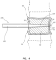
- FIG. 4 is a cross-sectional view of a vertebral probe according to some embodiments fully extending through a vertebral body with the probe tip extending through the distal vertebral cortex of the body;
- FIG. 5 depicts a vertebral probe according to other embodiments
- FIG. 6 is a side elevation view of a tip of a vertebral probe viewed along an elongated axis of the probe according to some embodiments.
- FIG. 7 is a side elevation view of another tip of a vertebral probe viewed along an elongated axis of the probe according to still other embodiments.
- the term “substantially” refers to the complete or nearly complete extent or degree of an action, characteristic, property, state, structure, item, or result to function as indicated.
- an object that is “substantially” cylindrical or “substantially” perpendicular would mean that the object/feature is either cylindrical/perpendicular or nearly cylindrical/perpendicular so as to result in the same or nearly the same function.
- the exact allowable degree of deviation provided by this term may depend on the specific context.
- the use of “substantially” is equally applicable when used in a negative connotation to refer to the complete or near complete lack of an action, characteristic, property, state, structure, item, or result.
- structure which is “substantially free of” a bottom would either completely lack a bottom or so nearly completely lack a bottom that the effect would be effectively the same as if it completely lacked a bottom.
- the term “about” is used to provide flexibility to a numerical range endpoint by providing that a given value may be “a little above” or “a little below” the endpoint while still accomplishing the function associated with the range.
- FIG. 1 depicts a vertebral probe 100 that may be used for various surgical procedures, such as, in preferred embodiments and implementations, scoliosis or other fusionless spinal surgeries.
- probe 100 may be used to facilitate screw or other anchor placement in a vertebral body or other bone.
- the depicted vertebral probe 100 is specifically configured to facilitate bicortical purchase prior to placement of a vertebral screw (not shown) that extends all the way through the vertebral body—i.e., through the proximal cortical wall, through the cancellous bone, and through the distal cortical wall.
- Placement of screws or other anchors in this manner may be particularly useful for fusionless scoliosis surgical procedures, which typically require high strength attachment points to the spinal column and therefore often warrant use of screws that extend through two opposing cortical walls of a vertebral body. Because such procedures are typically performed in very sensitive areas of patient anatomy and can be very dangerous, it may be useful to provide a probe to make the screw placement procedure safer and/or easier.
- Probe 100 provides various features that may be useful for these and/or other purposes.
- probe 100 comprises a cylindrical portion 102 , a tapering portion 104 , and a tip 105 .
- Tip 105 is designed to facilitate precise, safe, and/or repeatable positioning of probe 100 through a vertebral body, which may be useful to guide bone screws or other anchors through the vertebral body, particularly when bicortical purchase of the screws/anchors is required or desired.
- tip 105 comprises a shape that, in at least one dimension, is less than that of the adjacent probe body (in the depicted embodiment tapering portion 104 ) so as to create one or more ledges or shelves 107 , the purpose of which will be explained below.
- two shelves 107 A and 107 B are formed above and below tip 105 , as shown in FIG. 1 .
- tip 105 extends at least substantially at a right angle relative to shelves 107 A and 107 B
- one or more tapering, smooth, and/or otherwise less sharp shelves may be formed instead.
- FIG. 1 As also shown in FIG.
- tip 105 may comprise flattened upper and/or lower surfaces so as to form a plate or plate-like shape.
- tip 105 may differ, sharply differ in some such embodiments, from the shape of the shaft of probe 100 adjacent to tip 105 , which may be rounded or at least substantially rounded in cross-section.
- tip 105 may comprise bulbous, curved, and/or rounded surfaces.
- smooth surfaces may be preferred for certain applications and embodiments, it is also contemplated that roughened surfaces may be useful for certain procedures.
- distal end of tip 105 is rounded, as shown in both FIGS. 1 and 2 , when viewed from both the side view of FIG. 1 and the top view of FIG. 2 , in other embodiments it may be desirable to form tip 105 with a sharpened distal end, which sharpening may take place in one or more dimensions so as to form, for example, either a sharpened blade-like tip or a pointed tip at the distal end of probe 100 .
- the distal end of the tip 105 may be configured specifically to avoid or be devoid of any sharp points or edges, given, for example, the nature of the delicate anatomy surrounding the vertebral column.
- the tip may be rounded or otherwise blunt and/or non-sharp.
- it may be provided to provide a blunt tip that is not smooth.
- the distal surface of the tip 105 that is configured to contact a cortical wall of a vertebral body may be surface roughened to prevent slippage.
- providing a blunt tip that avoids sharp points and/or edges may be desirable around sensitive patient anatomy and may be feasible due to the cortical wall of the vertebral bodies being less hard and easier to penetrate than other areas of the spine, such as the pedicle region of the spine.
- providing a dull/blunt, unthreaded tip may allow for precise positioning through the cortical wall of a vertebral body and may allow for precise advancement without destroying the ability of a subsequent bone screw or other bone anchor to obtain proper purchase within the vertebral body.
- probe 100 proximal of tip 105 may also be provided to improve functionality for certain procedures, such as to prepare a vertebral body for acceptance of a bicortical-purchase screw or other bone anchor for use in, for example, fusionless scoliosis surgeries and the like.
- the embodiment depicted in FIGS. 1 and 2 comprises a non-tapering and/or cylindrical section 102 and a tapering section 104 positioned adjacent to and distal of non-tapering section 102 .
- providing a tapering section 104 increases the force required in order to tamp the probe through a vertebral body or other bone portion.
- the degree of tapering on tapering section 104 may extend smoothly and apply to tip 105 when viewed from one perspective and/or in two dimensions.
- tip 105 may not be tapered in any direction/dimension or, alternatively, may taper but not smoothly with respect to tapering section 104 .
- a ledge or shelf may be formed between tip 105 and an adjacent section, whether tapering or not, when viewed from any perspective.
- the shelf/ledge may extend about the entire perimeter of tip 105 , or may extend about the perimeter of tip 105 along all but one side of tip 105 , if desired.
- the dimensions of various portions of probe 100 may also be important and may be related to particular dimensions of patient anatomy, such as the dimensions of a vertebral body and/or a specific portion/aspect of a vertebral body.
- distance D 1 may be at least as long as the distance between opposing outer cortical walls of a particular vertebral body through which the probe is to be inserted.
- distance D 1 may be the same, or at least substantially the same, as this distance.
- distance D 1 may vary depending upon the particular patient and/or the particular vertebral body that is to the subject of a surgical procedure.
- some embodiments may comprise a set of probes having different dimensions according to a particular portion of the vertebral column, such as a thoracic probe (22-35 mm) and a lumbar probe (35-45 mm).
- D 2 may be between about 22 and about 35 mm for a thoracic probe and may be between about 35 and about 45 mm for a lumbar probe.
- distance D 2 may be between about 20 and about 50 mm. In some such embodiments, distance D 2 may be between about 22 and about 45 mm.
- distance D 2 this distance may also vary depending upon the patient and portion of the vertebral column being probed. However, in some particularly preferred embodiments that may be generally useful for a variety of different patient anatomies, D 2 may be between about 2 and about 3 mm for a thoracic probe and may be between about 3 and about 5 mm for a lumbar probe. Thus, more generally speaking, in certain preferred embodiments, distance D 1 may be between about 2 and about 6 mm. In some such embodiments, distance D 1 may be between about 3 and about 5 mm.
- tip 105 is preferably less than that of the adjacent portion/section of probe 100 so as to provide one or more shelves, ledges, or other features—such as shelves 107 A and 107 B—for providing tactile sensation indicative of probe location, as described below, and/or controlling advancement of probe 100 .
- tip 105 and/or the remaining portion of probe 100 that is configured and/or designed to extend through bone comprises a maximal cross-sectional dimension that is less than the major diameter of a thread depth of a bone screw of which probe 100 is being used to facilitate entry. It may also be preferred that, in certain embodiments, tip 105 comprises a maximal cross-sectional dimension that is less than a major diameter and/or maximal cross-sectional dimension of a tip of such bone screw.
- tip 105 is depicted as rounded, it is contemplated that, in alternative designs, providing a flattened distal end, or an at least substantially flattened distal end, may be advantageous for certain purposes.
- FIGS. 3 A- 3 D depict various steps/stages during a process for using probe 100 according to certain preferred implementations of inventive methods.
- tip 105 of probe 100 is advanced to contact a proximal cortical wall of a vertebral body 50 .
- a smaller, less invasive opening 55 may be formed by tamping or otherwise advancing tip 105 only through the proximal cortical wall of vertebral body 50 .
- FIG. 3 B depicts probe 100 following the formation of an opening in the proximal cortical wall of vertebral body 50 by tip 105 . Due to the presence of one or more shelves 107 , after tip 105 penetrates the cortical wall, a relatively large differential in force is required to advance probe 100 further due to the blunt shelf 107 contacting the dense cortical bone. Moreover, a surgeon may be able to, by tactile feel alone, confirm that the probe 100 is in the position depicted in FIG. 3 B with the tip 105 extending into the vertebral body and the shelf 107 inhibiting further penetration.
- FIG. 3 C depicts the probe 100 being rotated to form a chamber with tip 105 that is circular, or at least substantially circular. This step may be performed once it has been determined that the initial penetration of the vertebral wall is in a suitable position to guide a bone screw or other anchor therethrough. Rotating the tip 105 in this manner may facilitate further penetration of probe 100 into the vertebral body 50 by providing less resistance to further tamping and/or advancement of probe 100 .
- the chamber formed by tip 105 may have the same, or at least substantially the same, diameter as the portion of the shaft immediately adjacent to tip 105 .
- the tip 105 may have a width that extends all of the way, or at least substantially all of the way, along the diameter of the adjacent shaft, as shown in FIG. 6 .
- FIG. 3 D depicts probe 100 after it has been fully extended through opposing cortical walls of vertebral body 50 .
- a distal opening 56 through the distal cortical wall is formed by tip 105 .
- tapering portion 104 preferably extends through the entire, or at least substantially the entire, length of at least the cancellous bone of vertebral body 50 , so as to provide continued resistance during tamping/advancement of probe 100 and prevent the probe from extending too far into and/or through vertebral body 50 .
- shelf 107 is in contact with the inner cortical wall of vertebral body 50 .
- shelf 107 may prevent or at least inhibit further advancement of probe 100 after tip 105 has extended through the distal cortical wall and/or may provide a surgeon with a tactile sensation to indicate the position of probe 100 illustrated in FIG. 3 D .
- the probing procedure and/or the following bone screw placement procedure may be made safer and more precise.
- probe 105 may be rotated again following penetration through the distal cortical wall, similar to the rotation discussed above in connection with FIG. 3 C . This may provide for a rounded hole that may be more suitable for guidance of the tip of a bone screw or anchor for bicortical screw purchase.
- FIG. 4 is a cross-sectional view of probe 100 fully extended through vertebral body 50 with shelf 107 contacting the inner cortical wall 52 and tapering portion 104 extending through the cancellous core 54 of vertebrae 50 .
- tapering portion 104 is configured to at least substantially match the width of vertebrae 50 in that it terminates just outside the proximal opening 55 in cortical shell 52 .
- other embodiments are contemplated that may include non-tapering portions configured to extend into a vertebral body, as discussed below, or that taper along the entire length of the probe.
- FIG. 5 depicts a vertebral probe 500 according to other embodiments.
- Probe 500 differs from probe 100 in several respects, any one or more of which may be applied to probe 100 , or vice versa, in a piecemeal fashion as desired.
- probe 500 comprises two non-tapering portions, namely, a first or proximal non-tapering portion 502 A and a second or distal non-tapering portion 502 B.
- a tapering portion 504 is positioned in between non-tapering portions 502 A and 502 B.
- Non-tapering portion 502 B is configured to extend through a vertebral body during a probing procedure. Providing one or more such non-tapering portions may be useful to allow for easier penetration/excavation during this procedure, but preferably only for a precise, predetermined length that may be dictated by and/or correspond with the anatomy of the vertebral body being probed.
- the tamping or other advancement of probe 500 may then be slowed by providing an adjacent tapering portion 504 , which may add to the force required to advance the probe 500 further.
- the degree of force added may be proportional to the degree of tapering and may vary as desired depending upon other features of the probe, the structure of the vertebrae, and/or surrounding patient anatomy.
- non-tapering section 502 B may comprise a distance D 3 of between about 12 mm and about 20 mm for a small probe (with a more preferred distance being about 16 mm), between about 18 mm and about 25 mm for a medium probe (with a more preferred distance being about 21 mm), and between about 23 mm and about 30 mm for a large probe (with a more preferred distance being about 26 mm).
- Tapering section 504 may comprise a distance D 2 , which may be any desired length but preferably sufficiently long such that when probe 500 is fully positioned through a vertebral body with the tip protruding through the distal cortical wall, tapering section 504 is long enough to extend through the proximal cortical wall opening to provide resistance to advancement of the probe 500 during and/or prior to breach of the distal cortical wall.
- Some embodiments may provide for a series of probes for use in connection with different patients and/or different vertebral bodies.
- the “working section” of the probe in other words, the portion of the probe that will enter the vertebrae, may be specifically tailored to the typical width of a vertebrae and therefore may have various distances that are proportional to one another.
- the distance D 3 may be between about five and about seven times the length of D 1 .
- the tapering section which may act to inhibit advancement of the probe within a vertebral body, may begin at or near the point at which the tip makes contact with the inner surface of the distal cortical wall, which may provide enhanced safety and provide a surgeon with a tactile feel that is associated with this portion of the advancement.
- D 1 may be between about 10 and about 25% of the length of D 3 .
- probe 500 further comprises a tip 505 defined in part by shelf 507 .
- tip 505 is preferably configured to allow for penetration through a cortical wall or other high-density bone portion and substantially increase the amount of force required to advance probe 500 further by providing a shelf for contacting this high-density wall.
- a surgeon will preferably be able to feel when shelf 507 has contacted both the proximal and distal cortical walls to assist in precise and safe placement of the probe and the subsequent bone screw/anchor.
- distance D 1 of tip 505 may be between about 2 and about 3 mm for a thoracic probe and may be between about 3 and about 5 mm for a lumbar probe.
- distance D 1 may be between about 2 and about 6 mm. In some such embodiments, distance D 1 may be between about 3 and about 5 mm.
- Probe 500 also comprises several other features not shown or described in connection with probe 100 .
- probe 500 comprises a series of markings configured to further facilitate ease of use, safety, and/or subsequent screw/anchor placement. More particularly, probe 500 comprises a series of alphanumerical markings 510 along with a series of more precise markings (dash lines in the depicted embodiment) that may allow a surgeon to take very precise measurements of the vertebral anatomy and/or receive a very precise indication of the current placement of the probe 500 .
- probe 500 comprises a first series of dash lines 514 A comprising relatively thin lines, a second series of dash lines 514 B adjacent to the first series 514 A comprising relatively thicker lines, a third series of dash lines 514 C comprising still different dash lines (of a different color), and so on.
- a surgeon may be provided with a more general view, once the surgeon becomes familiar with the marking system, of the probe 500 placement without having to rely on the alphanumerical markings 510 , which may be most useful following full advancement of the probe 500 to provide the surgeon with a very precise indication of the width of the vertebral body to allow for screw selection.
- sections may be colored, patterned, and/or otherwise marked distinctly.
- each of the sections in between adjacent alphanumerical markings 510 may be colored, patterned, and/or otherwise marked distinctly.
- section 512 A may therefore comprise a first color
- section 512 B may comprise a second color distinct from the first color.
- Sections immediately adjacent to sections 512 A and 512 B may similarly be visibly distinct from their adjacent sections. Thus, these sections are depicted as uncolored in the embodiment of FIG. 5 .
- These more general markings may allow a surgeon to easily and immediately receive a general indication of the extent to which the probe 500 has penetrated a vertebral body. For example, a green section may indicate that the probe is in a central location within the vertebral body, a yellow section may indicate that the distal cortical wall is approaching, and a red section may indicate danger, such as that the probe is near or beyond the distal cortical wall. In some contemplated embodiments, one or more of these marking features may therefore be provided without the novel probe tip 505 disclosed herein.
- the adjacent sections 512 with distinct markings spanning multiple more precise markings and the distinct patterns of dash lines 514 between adjacent sections are examples of means for coarsely visualizing a current location of a vertebral probe within a vertebral body.
- the finer measurements provided by dash lines 514 may then be used, for example, to provide a precise measurement of the span of a vertebral body, which may be useful for bone screw selection.
- the markings on the probe may be visible from every side and/or angle of the probe.
- duplicate markings may be positioned on the opposite side, or more than two sets of such markings may be provided.
- some or all of the markings may be staggered so that each marking is positioned slightly above or below the adjacent markings such that the markings gradually rotate about the probe.
- FIG. 6 is an axial, front elevation view of a tip 605 of a vertebral probe according to some embodiments.
- tip 605 comprises flattened upper and lower surfaces and these surfaces may extend smoothly on the sides into the body of the probe.
- this design provides upper and lower shelves 607 A and 607 B, respectively, which, as discussed above, facilitate positioning of a probe through proximal and/or distal cortical walls adjacent to tip and may provide for tactile feel of such probe position.
- the tip 705 may protrude from a central region of a single shelf 707 .
- the sides of the probe tip may taper towards a rounded or pointed tip to form a tongue-like shape or may extend parallel to one another to form more of a table-top shape if desired.
- a probe body comprising a circular shape in cross-section with a tip that comprises a non-circular and/or non-symmetrical shape in cross-section, if not the flattened or “duckbill” shapes depicted in the figures.
- Any methods disclosed herein comprise one or more steps or actions for performing the described method.
- the method steps and/or actions may be interchanged with one another.
- the order and/or use of specific steps and/or actions may be modified.
- any reference to “one embodiment,” “an embodiment,” or “the embodiment” means that a particular feature, structure, or characteristic described in connection with that embodiment is included in at least one embodiment.
- the quoted phrases, or variations thereof, as recited throughout this specification are not necessarily all referring to the same embodiment.
Abstract
Description
Claims (20)
Priority Applications (2)
| Application Number | Priority Date | Filing Date | Title |
|---|---|---|---|
| US16/526,664 US11648000B2 (en) | 2018-07-30 | 2019-07-30 | Vertebral probes and related surgical methods |
| US17/063,674 US20210045784A1 (en) | 2018-07-30 | 2020-10-05 | Cortical/cancellous bone probes and related surgical methods |
Applications Claiming Priority (2)
| Application Number | Priority Date | Filing Date | Title |
|---|---|---|---|
| US201862712158P | 2018-07-30 | 2018-07-30 | |
| US16/526,664 US11648000B2 (en) | 2018-07-30 | 2019-07-30 | Vertebral probes and related surgical methods |
Related Child Applications (1)
| Application Number | Title | Priority Date | Filing Date |
|---|---|---|---|
| US17/063,674 Continuation-In-Part US20210045784A1 (en) | 2018-07-30 | 2020-10-05 | Cortical/cancellous bone probes and related surgical methods |
Publications (2)
| Publication Number | Publication Date |
|---|---|
| US20200029949A1 US20200029949A1 (en) | 2020-01-30 |
| US11648000B2 true US11648000B2 (en) | 2023-05-16 |
Family
ID=69177920
Family Applications (1)
| Application Number | Title | Priority Date | Filing Date |
|---|---|---|---|
| US16/526,664 Active 2040-08-26 US11648000B2 (en) | 2018-07-30 | 2019-07-30 | Vertebral probes and related surgical methods |
Country Status (1)
| Country | Link |
|---|---|
| US (1) | US11648000B2 (en) |
Citations (42)
| Publication number | Priority date | Publication date | Assignee | Title |
|---|---|---|---|---|
| US5318570A (en) * | 1989-01-31 | 1994-06-07 | Advanced Osseous Technologies, Inc. | Ultrasonic tool |
| US5387213A (en) | 1991-02-05 | 1995-02-07 | Safir S.A.R.L. | Osseous surgical implant particularly for an intervertebral stabilizer |
| US5827290A (en) * | 1996-10-25 | 1998-10-27 | Bradley; Gary W. | Automatic impact device |
| US5951560A (en) | 1997-10-15 | 1999-09-14 | Applied Biological Concepts, Inc. | Wedge orthopedic screw |
| US6299613B1 (en) | 1999-04-23 | 2001-10-09 | Sdgi Holdings, Inc. | Method for the correction of spinal deformities through vertebral body tethering without fusion |
| US20020032447A1 (en) * | 2000-09-01 | 2002-03-14 | Stuart Weikel | Tools and methods for creating cavities in bone |
| US20020055783A1 (en) * | 2000-05-01 | 2002-05-09 | Tallarida Steven J. | System and method for joint resurface repair |
| US20020077641A1 (en) * | 1988-06-13 | 2002-06-20 | Michelson Gary Karlin | Apparatus and method of inserting spinal implants |
| US20020082598A1 (en) | 2000-06-23 | 2002-06-27 | Teitelbaum George P. | Percutaneous vertebral fusion system |
| US20020143343A1 (en) * | 2001-03-27 | 2002-10-03 | Surgical Dynamics, Inc. | Method and apparatus for spinal implant insertion |
| US20020173794A1 (en) * | 2001-05-16 | 2002-11-21 | Inion Ltd. | Tool for making threaded surgical holes |
| US20030018337A1 (en) * | 2001-07-17 | 2003-01-23 | Davis Reginald J. | Bone drill and tap combination |
| US20030036764A1 (en) * | 1999-10-13 | 2003-02-20 | Hamada James S. | Spinal fusion instrumentation, implant and method |
| US20030109883A1 (en) * | 2001-12-06 | 2003-06-12 | Hiromi Matsuzaki | Surgical instruments and a set of surgical instruments for use in treatment of vertebral bodies |
| US20050070907A1 (en) * | 2003-09-25 | 2005-03-31 | Abernathie Dennis L. | Method and device for drilling and tapping a bore for a bone screw |
| US20050171551A1 (en) * | 2003-10-21 | 2005-08-04 | William Sukovich | Instrument and method for preparing a bone to receive an implant |
| US20060235306A1 (en) * | 2005-04-15 | 2006-10-19 | Integra Lifesciences (Ireland) | Ultrasonic horn for removal of hard tissue |
| US20070219554A1 (en) * | 2002-10-30 | 2007-09-20 | Landry Michael E | Spinal stabilization systems and methods |
| US7285121B2 (en) | 2001-11-05 | 2007-10-23 | Warsaw Orthopedic, Inc. | Devices and methods for the correction and treatment of spinal deformities |
| US7297146B2 (en) | 2004-01-30 | 2007-11-20 | Warsaw Orthopedic, Inc. | Orthopedic distraction implants and techniques |
| WO2009128074A1 (en) | 2008-04-16 | 2009-10-22 | Tavor [I.T.N] Ltd. | Endosseous implant with interior and exterior threads |
| US20090312782A1 (en) * | 2008-06-13 | 2009-12-17 | Maxwell Choongwon Park | Method and apparatus for repairing tendons |
| US7637978B2 (en) | 2007-12-14 | 2009-12-29 | Hyundai Motor Company | Intake duct system for an engine |
| US7691131B2 (en) | 2000-06-30 | 2010-04-06 | Sofamor S.N.C. | Intervertebral connecting device |
| US20100131010A1 (en) | 2007-07-24 | 2010-05-27 | Henry Graf | Extra discal intervertebral stabilization element for arthrodesis |
| US7727258B2 (en) | 2000-12-01 | 2010-06-01 | Warsaw Orthopedic, Inc. | Intervertebral stabilizing device |
| US7845945B2 (en) | 2004-01-28 | 2010-12-07 | Stanton R. Canter | Anchoring element for use in bone |
| US20110054537A1 (en) * | 2009-08-28 | 2011-03-03 | Zimmer Spine Austin, Inc. | Fusion method and pedicle access tool |
| US20110238069A1 (en) * | 2010-02-11 | 2011-09-29 | Arthrex, Inc. | Threaded hole forming device |
| US8172880B2 (en) | 1999-12-01 | 2012-05-08 | Warsaw Orthopedic, Inc. | Intervertebral stabilising device |
| US8177810B2 (en) | 2007-07-17 | 2012-05-15 | Anova Corporation | Methods of annulus and ligament reconstruction using flexible devices |
| US8221457B2 (en) | 2001-10-18 | 2012-07-17 | Ldr Medical | Progressive approach osteosynthesis device and preassembly method |
| US20120189984A1 (en) | 2011-01-26 | 2012-07-26 | Holmes David Lc | Apical cutting thread dental implant |
| US20130253587A1 (en) | 2012-03-20 | 2013-09-26 | Warsaw Orthopedic, Inc. | Spinal systems and methods for correction of spinal disorders |
| US8641736B2 (en) | 2012-01-20 | 2014-02-04 | Warsaw Orthopedic, Inc. | Vertebral fastener system |
| US8979874B2 (en) | 2006-04-21 | 2015-03-17 | Davol, Inc. | Method and apparatus for surgical fastening |
| US9433442B2 (en) | 2014-01-23 | 2016-09-06 | Warsaw Orthopedic, Inc. | Spinal correction system and method |
| US20160374661A1 (en) * | 2009-10-28 | 2016-12-29 | Smith & Nephew, Inc. | Threaded suture anchor |
| WO2017127532A1 (en) | 2016-01-19 | 2017-07-27 | K2M, Inc. | Spinal correction system and method of use thereof |
| US9833230B2 (en) | 2006-09-29 | 2017-12-05 | Biomet Sports Medicine, Llc | Fracture fixation device |
| US10179015B2 (en) | 2014-08-01 | 2019-01-15 | Ldr Medical | Bone implants |
| US20200155728A1 (en) * | 2018-11-20 | 2020-05-21 | BioMark, LLC | Device with an Open Cell Element |
-
2019
- 2019-07-30 US US16/526,664 patent/US11648000B2/en active Active
Patent Citations (42)
| Publication number | Priority date | Publication date | Assignee | Title |
|---|---|---|---|---|
| US20020077641A1 (en) * | 1988-06-13 | 2002-06-20 | Michelson Gary Karlin | Apparatus and method of inserting spinal implants |
| US5318570A (en) * | 1989-01-31 | 1994-06-07 | Advanced Osseous Technologies, Inc. | Ultrasonic tool |
| US5387213A (en) | 1991-02-05 | 1995-02-07 | Safir S.A.R.L. | Osseous surgical implant particularly for an intervertebral stabilizer |
| US5827290A (en) * | 1996-10-25 | 1998-10-27 | Bradley; Gary W. | Automatic impact device |
| US5951560A (en) | 1997-10-15 | 1999-09-14 | Applied Biological Concepts, Inc. | Wedge orthopedic screw |
| US6299613B1 (en) | 1999-04-23 | 2001-10-09 | Sdgi Holdings, Inc. | Method for the correction of spinal deformities through vertebral body tethering without fusion |
| US20030036764A1 (en) * | 1999-10-13 | 2003-02-20 | Hamada James S. | Spinal fusion instrumentation, implant and method |
| US8172880B2 (en) | 1999-12-01 | 2012-05-08 | Warsaw Orthopedic, Inc. | Intervertebral stabilising device |
| US20020055783A1 (en) * | 2000-05-01 | 2002-05-09 | Tallarida Steven J. | System and method for joint resurface repair |
| US20020082598A1 (en) | 2000-06-23 | 2002-06-27 | Teitelbaum George P. | Percutaneous vertebral fusion system |
| US7691131B2 (en) | 2000-06-30 | 2010-04-06 | Sofamor S.N.C. | Intervertebral connecting device |
| US20020032447A1 (en) * | 2000-09-01 | 2002-03-14 | Stuart Weikel | Tools and methods for creating cavities in bone |
| US7727258B2 (en) | 2000-12-01 | 2010-06-01 | Warsaw Orthopedic, Inc. | Intervertebral stabilizing device |
| US20020143343A1 (en) * | 2001-03-27 | 2002-10-03 | Surgical Dynamics, Inc. | Method and apparatus for spinal implant insertion |
| US20020173794A1 (en) * | 2001-05-16 | 2002-11-21 | Inion Ltd. | Tool for making threaded surgical holes |
| US20030018337A1 (en) * | 2001-07-17 | 2003-01-23 | Davis Reginald J. | Bone drill and tap combination |
| US8221457B2 (en) | 2001-10-18 | 2012-07-17 | Ldr Medical | Progressive approach osteosynthesis device and preassembly method |
| US7285121B2 (en) | 2001-11-05 | 2007-10-23 | Warsaw Orthopedic, Inc. | Devices and methods for the correction and treatment of spinal deformities |
| US20030109883A1 (en) * | 2001-12-06 | 2003-06-12 | Hiromi Matsuzaki | Surgical instruments and a set of surgical instruments for use in treatment of vertebral bodies |
| US20070219554A1 (en) * | 2002-10-30 | 2007-09-20 | Landry Michael E | Spinal stabilization systems and methods |
| US20050070907A1 (en) * | 2003-09-25 | 2005-03-31 | Abernathie Dennis L. | Method and device for drilling and tapping a bore for a bone screw |
| US20050171551A1 (en) * | 2003-10-21 | 2005-08-04 | William Sukovich | Instrument and method for preparing a bone to receive an implant |
| US7845945B2 (en) | 2004-01-28 | 2010-12-07 | Stanton R. Canter | Anchoring element for use in bone |
| US7297146B2 (en) | 2004-01-30 | 2007-11-20 | Warsaw Orthopedic, Inc. | Orthopedic distraction implants and techniques |
| US20060235306A1 (en) * | 2005-04-15 | 2006-10-19 | Integra Lifesciences (Ireland) | Ultrasonic horn for removal of hard tissue |
| US8979874B2 (en) | 2006-04-21 | 2015-03-17 | Davol, Inc. | Method and apparatus for surgical fastening |
| US9833230B2 (en) | 2006-09-29 | 2017-12-05 | Biomet Sports Medicine, Llc | Fracture fixation device |
| US8177810B2 (en) | 2007-07-17 | 2012-05-15 | Anova Corporation | Methods of annulus and ligament reconstruction using flexible devices |
| US20100131010A1 (en) | 2007-07-24 | 2010-05-27 | Henry Graf | Extra discal intervertebral stabilization element for arthrodesis |
| US7637978B2 (en) | 2007-12-14 | 2009-12-29 | Hyundai Motor Company | Intake duct system for an engine |
| WO2009128074A1 (en) | 2008-04-16 | 2009-10-22 | Tavor [I.T.N] Ltd. | Endosseous implant with interior and exterior threads |
| US20090312782A1 (en) * | 2008-06-13 | 2009-12-17 | Maxwell Choongwon Park | Method and apparatus for repairing tendons |
| US20110054537A1 (en) * | 2009-08-28 | 2011-03-03 | Zimmer Spine Austin, Inc. | Fusion method and pedicle access tool |
| US20160374661A1 (en) * | 2009-10-28 | 2016-12-29 | Smith & Nephew, Inc. | Threaded suture anchor |
| US20110238069A1 (en) * | 2010-02-11 | 2011-09-29 | Arthrex, Inc. | Threaded hole forming device |
| US20120189984A1 (en) | 2011-01-26 | 2012-07-26 | Holmes David Lc | Apical cutting thread dental implant |
| US8641736B2 (en) | 2012-01-20 | 2014-02-04 | Warsaw Orthopedic, Inc. | Vertebral fastener system |
| US20130253587A1 (en) | 2012-03-20 | 2013-09-26 | Warsaw Orthopedic, Inc. | Spinal systems and methods for correction of spinal disorders |
| US9433442B2 (en) | 2014-01-23 | 2016-09-06 | Warsaw Orthopedic, Inc. | Spinal correction system and method |
| US10179015B2 (en) | 2014-08-01 | 2019-01-15 | Ldr Medical | Bone implants |
| WO2017127532A1 (en) | 2016-01-19 | 2017-07-27 | K2M, Inc. | Spinal correction system and method of use thereof |
| US20200155728A1 (en) * | 2018-11-20 | 2020-05-21 | BioMark, LLC | Device with an Open Cell Element |
Also Published As
| Publication number | Publication date |
|---|---|
| US20200029949A1 (en) | 2020-01-30 |
Similar Documents
| Publication | Publication Date | Title |
|---|---|---|
| US9271742B2 (en) | System for joint fusion | |
| US10413339B2 (en) | Bone anchors and surgical instruments with integrated guide tips | |
| US20050004593A1 (en) | Non cannulated dilators | |
| EP1836970B2 (en) | Marked suture | |
| US7887548B2 (en) | Screw insertion guide tube with window | |
| US20060224161A1 (en) | Depth gauge apparatus and methods | |
| US20110196372A1 (en) | Bone Fixing Material and Thighbone Fixing System | |
| US20100004693A1 (en) | Cam locking spine stabilization system and method | |
| US20090005787A1 (en) | Device and system for implanting polyaxial bone fasteners | |
| US20090287257A1 (en) | Cervical plate | |
| RU2659017C2 (en) | Screw with universal length and cutting tools | |
| JP7202694B2 (en) | Handheld device for use in medical procedures | |
| US10285745B2 (en) | Orthopedic screws | |
| KR101405071B1 (en) | Puncturing tool | |
| WO2019138742A1 (en) | Puncture tool guiding device | |
| KR20160037927A (en) | Perforating trocar | |
| US20230110238A1 (en) | Surgical device for insertion of guide wire and pedicle screw | |
| US10842448B2 (en) | Device and method for determining proper screw or implant size during orthopedic surgery | |
| US11648000B2 (en) | Vertebral probes and related surgical methods | |
| US20210045784A1 (en) | Cortical/cancellous bone probes and related surgical methods | |
| EP2879587B1 (en) | Depth controlled jamshidi needle | |
| US20180303604A1 (en) | Tissue Fixation Systems, Delivery Tools, and Associated Methods and Kits | |
| US20220031306A1 (en) | Surgical cannula with closure guides | |
| JP2010184026A (en) | Excision region marker instrument | |
| JP2013528074A (en) | Minimally invasive spinal surgery instrument and use thereof |
Legal Events
| Date | Code | Title | Description |
|---|---|---|---|
| AS | Assignment |
Owner name: CRICKET K. BRAUN AND JOHN T. BRAUN FAMILY LLC, VERMONT Free format text: ASSIGNMENT OF ASSIGNORS INTEREST;ASSIGNOR:BRAUN, JOHN T.;REEL/FRAME:049908/0327 Effective date: 20190730 |
|
| FEPP | Fee payment procedure |
Free format text: ENTITY STATUS SET TO UNDISCOUNTED (ORIGINAL EVENT CODE: BIG.); ENTITY STATUS OF PATENT OWNER: SMALL ENTITY |
|
| FEPP | Fee payment procedure |
Free format text: ENTITY STATUS SET TO SMALL (ORIGINAL EVENT CODE: SMAL); ENTITY STATUS OF PATENT OWNER: SMALL ENTITY |
|
| STPP | Information on status: patent application and granting procedure in general |
Free format text: DOCKETED NEW CASE - READY FOR EXAMINATION |
|
| AS | Assignment |
Owner name: BRAUNVEST LLC, VERMONT Free format text: ASSIGNMENT OF ASSIGNORS INTEREST;ASSIGNOR:CRICKET K. BRAUN AND JOHN T. BRAUN, MD FAMILY LLC;REEL/FRAME:052718/0152 Effective date: 20200517 |
|
| STPP | Information on status: patent application and granting procedure in general |
Free format text: NON FINAL ACTION MAILED |
|
| STPP | Information on status: patent application and granting procedure in general |
Free format text: RESPONSE TO NON-FINAL OFFICE ACTION ENTERED AND FORWARDED TO EXAMINER |
|
| STPP | Information on status: patent application and granting procedure in general |
Free format text: FINAL REJECTION MAILED |
|
| STPP | Information on status: patent application and granting procedure in general |
Free format text: RESPONSE AFTER FINAL ACTION FORWARDED TO EXAMINER |
|
| STPP | Information on status: patent application and granting procedure in general |
Free format text: ADVISORY ACTION MAILED |
|
| STPP | Information on status: patent application and granting procedure in general |
Free format text: DOCKETED NEW CASE - READY FOR EXAMINATION |
|
| STPP | Information on status: patent application and granting procedure in general |
Free format text: NON FINAL ACTION MAILED |
|
| STPP | Information on status: patent application and granting procedure in general |
Free format text: RESPONSE TO NON-FINAL OFFICE ACTION ENTERED AND FORWARDED TO EXAMINER |
|
| STCF | Information on status: patent grant |
Free format text: PATENTED CASE |