EP2360792A2 - Elektrischer Zwitterkontakt - Google Patents
Elektrischer Zwitterkontakt Download PDFInfo
- Publication number
- EP2360792A2 EP2360792A2 EP11159090A EP11159090A EP2360792A2 EP 2360792 A2 EP2360792 A2 EP 2360792A2 EP 11159090 A EP11159090 A EP 11159090A EP 11159090 A EP11159090 A EP 11159090A EP 2360792 A2 EP2360792 A2 EP 2360792A2
- Authority
- EP
- European Patent Office
- Prior art keywords
- contact
- blades
- central body
- cage
- electrical contact
- Prior art date
- Legal status (The legal status is an assumption and is not a legal conclusion. Google has not performed a legal analysis and makes no representation as to the accuracy of the status listed.)
- Granted
Links
Images


Classifications
-
- H—ELECTRICITY
- H01—ELECTRIC ELEMENTS
- H01R—ELECTRICALLY-CONDUCTIVE CONNECTIONS; STRUCTURAL ASSOCIATIONS OF A PLURALITY OF MUTUALLY-INSULATED ELECTRICAL CONNECTING ELEMENTS; COUPLING DEVICES; CURRENT COLLECTORS
- H01R13/00—Details of coupling devices of the kinds covered by groups H01R12/70 or H01R24/00 - H01R33/00
- H01R13/02—Contact members
- H01R13/28—Contacts for sliding cooperation with identically-shaped contact, e.g. for hermaphroditic coupling devices
-
- H—ELECTRICITY
- H01—ELECTRIC ELEMENTS
- H01R—ELECTRICALLY-CONDUCTIVE CONNECTIONS; STRUCTURAL ASSOCIATIONS OF A PLURALITY OF MUTUALLY-INSULATED ELECTRICAL CONNECTING ELEMENTS; COUPLING DEVICES; CURRENT COLLECTORS
- H01R13/00—Details of coupling devices of the kinds covered by groups H01R12/70 or H01R24/00 - H01R33/00
- H01R13/02—Contact members
- H01R13/04—Pins or blades for co-operation with sockets
- H01R13/05—Resilient pins or blades
Definitions
- the present invention relates to an electrical connection device provided with a pair of contact elements having a first contact element and a second contact element complementary to the first.
- the first and second contact elements are contact elements each provided with a multi-blade contact termination so as to produce hermaphroditic contact elements.
- a hermaphrodite contact is a contact having an interruptible contact front portion with a second contact of identical shape to the first.
- US 2002/0049005 A1 discloses a contact element provided with a connection termination provided with a plurality of metal contact blades disposed corolla and provided with external bulges adapted to make electrical contact with a complementary metal tubular contact element.
- the contact blades work in radial elasticity with respect to the longitudinal axis of the contact.
- this document does not describe a pair of contact elements each provided with a multi-blade contact termination so as to produce hermaphroditic contact elements.
- each contact element of a pair of hermaphroditic contact elements having the same behavior in electrical contact resistance and therefore in temperature during the passage of an intense current.
- the invention proposes an electrical contact according to claim 1.
- the blades have an upper face and a lower face, and electrical contact zones are formed between at least a portion of the upper faces of the blades and the inner face of a central body of said complementary contact.
- electrical contact zones are formed between at least a portion of the lower faces of the blades and the outer face of a central body of said complementary contact.
- the invention also relates to an electrical contact comprising at least one of the features defined by claims 2 to 9, taken in combination or in isolation, an electrical contact comprising at least one of the features defined by claims 10 to 16, taken in combination or in isolation, a connector comprising at least one of the features defined by claim 17 or an electrical contact according to claim 18.
- a device for protecting the blades of an electrical contact having a sliding element integral with the electrical contact and adapted to protect the contact blades by coming to cover them when the contact is not not inserted into a receptacle of the electrical contact to avoid any risk of bending or breaking the blades.
- the attached cage element comprises means for engaging the contact in a receptacle for receiving said contact of a connector housing receiving at least said contact.
- the contact is received in an insulating housing and the insulating housing comprises means for pushing the cage in the retracted position when the contact is inserted into the housing.
- the contact blades are protected by the cage element which protrudes from the front of the central body in the advanced position and when the contact is inserted into its cell of the housing. insulation, the cage member is pushed into the retracted position releasing the contact blades.
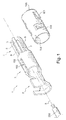
- the figure 1 represents an electrical contact 1 provided with a longitudinal axis (x) in which are successively realized a connection termination 2, a central body 3 and a contact termination 4.
- connection termination 2 is according to the example a crimp termination intended to receive a cable 200.
- the electrical contact is a tubular contact, symmetrical about the x-axis, made from a rolled blank rolled.
- the contact termination comprises a first plurality of blades 5 extending generally in the longitudinal direction of the electrical contact.
- This plurality of blades 5 is regularly distributed along the guide curve of a cylinder.
- the blades comprise an upper face 6 facing the outside of the cylinder, a lower face 7 facing the inside of the cylinder and side faces 8, 9 perpendicular to said upper and lower faces.
- the blades are made according to a general S-shape along their longitudinal axis, comprise a free end 11 bent towards the longitudinal axis x of the contact and an end 12 of connection to the central body in the course of a staircase so as to reduce the cross-section. the envelope of the blades relative to the section of the central body.
- the central body is a tube of inner section slightly smaller than the outer envelope surface of the blades.
- the central body receives an attached cage element 100 which will be described later.
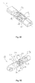
- FIGS. 2A to 2C represent a second type of contacts according to the invention, contacts without attached cage element.
- the contact 3 is a hermaphrodite contact which couples with a complementary contact having a contact section itself comprising a plurality of blades 5b interlocking between the blades of the first plurality of blades 5a of the first contact.
- Two contacts according to the invention 1a and 1b are represented before connection to the Figure 2A , being connected to the Figure 2B and connected to the Figure 2C .
- the blades 5a of the first contact are interlocked between complementary blades 5b of the second contact, the complementary electrical contact 1b, said blades complementary forming a second plurality of blades 5b fitting in the same manner between the blades of the first plurality of blades 5a.
- the two contacts are aligned on the same coupling axis head to tail with a rotation of one of the two contacts on the coupling axis so that the blades of the first contact are positioned in the recesses or spaces between the blades of the second contact.
- the contacts are offset in rotation along the x axis so that the blades 5a of a first of the contacts 1a are positioned between the blades 5b of the second of the contacts 1b.
- the blades of the plurality of blades 5a, 5b enter the central bodies 3b, 3a and electrical contact zones are formed between at least a portion of the upper faces 6 of the blades and an inner face 10a, 10b of the central bodies 3a, 3b of the complementary contacts 1a, 1b as shown in FIG. figure 3 .
- the blades are not in contact with the blades of the complementary contact but in contact with the inner face of the central body of the complementary or conjugate contact.
- the curved blades S comprise a segment 13 slightly inclined outwards between the ends 11 and 12, the outer face of the segment 13 rubbing against the inner face of the body 3.
- the contact pressure for the electrical connection is generated by the pressure of the central body on the blades because the central body is a tube of inner section slightly smaller than the outer envelope surface of the blades.
- the metal of the contacts is advantageously a highly spring-loaded metal alloy such as a cupro-beryllium alloy.
- the figure 4 schematizes the pressing forces of the blades 5a, 5b of a contact against the inner surface 10b, 10a of the central body 3b 3a of the other contact and the relative angular positioning of the blades of a contact relative to the blades of the other contact.
- the hermaphrodite contacts according to the invention are thus made such that said first and second pluralities of blades 5, 5a, 5b constitute parallel electrical connections between the central bodies 3, 3a, 3b of said electrical contact and complementary electrical contact 1, 1a, 1b.
- the contacts each comprise four blades, this number can be increased or reduced, for example as a function of the diameter of the contact and the section of the blades.
- FIGS. 5A to 5C represent a variant of the contact according to the invention for which the central body 3 is of generally parallelepipedal shape having an upper face 32, a lower face 33 and side flanks 34,35.
- the blades 51a, 52b are distributed on the upper face and the lower face of the contacts and have an upper face 52 facing the outside of the contact, a lower face 53 facing inwards. contact and flanks perpendicular to the upper face and lower face of the contacts.
- This embodiment is made from a folded cut blank.
- the blades of the plurality of blades 51a, 51b comprise an upper face 52 and a lower face 53 and electrical contact zones are formed between at least a portion of the upper faces 52 of the blades and an inner face 10a, 10b of the central body 31a, 31b of the complementary contact 1a, 1b.
- the first and second plurality of blades 51a, 51b here also constitute parallel electrical connections between the central bodies 31a, 31b of said electrical contact and complementary electrical contact 1a, 1b.
- the blades of this second embodiment are made according to a general S-shaped profile, comprise a free end 11 curved towards the longitudinal axis x of the contact included in a longitudinal plane of symmetry of the central body 31a, 31b of the contact and comprise an end 12 of connection to the central body in step of staircase so as to reduce the section of the envelope of the blades relative to the section of the central body.
- two pairs of blades are disposed respectively at the end of the upper face 32 and the lower face 33 of the central body of the contact, the blades of a first pair being side by side and the blades of a second pair being spaced apart.
- the parallelepipedal contact of this example is a hermaphrodite contact for which the outer faces 52 of the blades come into contact with the inner face 10a, 10b of the central body.
- FIGS. 5D and 5E correspond to a fourth embodiment for which the contacts comprise, with respect to the third example, in addition to blades coming into contact with the interior of the central portion, blades coming into contact with the outside of the central portion.
- At least some of the blades are internal contact blades through which electrical contact zones are formed between at least a portion upper faces 52 of the blades and the inner face 10, 10a, 10b of the central body 31a, 31b of said complementary contact 1a, 1b and at least some of the blades are external contact blades through which electrical contact zones are made between at least a portion of the lower faces 53 of the blades and the outer face 10c, 10d of the central body 3a, 3b of said complementary contact 1a, 1b.
- a first plurality of blades 51a, 51b of a first electrical contact 1a with a second plurality of blades 51a, 51b of a second complementary contact 1b constitute parallel electrical connections between the central bodies 31a, 31b of the electrical contacts 1a, 1b.
- the blades contacting the inside and outside of the central bodies are made according to a general S profile.
- the blades with internal contact have a free end 11 bent towards the longitudinal axis of the contact and the outer contact blades have a free end 11 'bent in a direction away from the longitudinal axis (x) of the contact.
- each contact 1a 1b advantageously comprises 4 pairs of contacts, either on each of the upper 32 and lower 31 faces, a pair of internal contact blades and a pair of blades with external contact, which makes a total of 16 connection points.
- the current capacity of the contact is increased.
- it allows a pinch of the thickness of the sheet constituting the faces of the central body between the internal contact blades and the external contact blades, so that the accuracy of the contact pressure is mainly dependent on the thickness of the sheet and relatively less the manufacturing precision of the central body.
- the figure 7 schematically represents an electrical connector provided with contacts according to the figure 1 .
- the connector comprises a first housing 108 called a male housing in which a first contact 1a according to the invention is received and a second housing 109, a female housing receiving a second contact 1b according to the invention.
- Each of the housings 108, 109 has a skirt 111, 112, the skirt 111 of the male housing being received inside the skirt 112 of the female housing.
- the male housing 108 may include a second outer skirt 113 covering the coupling portion of the housings and forming, with the first skirt 111 of the male housing a baffle around the skirt 112 of the female housing.
- the Figures 8A and 8B respectively represent housings equipped with contacts according to the second embodiment, contact without attached cage element, and according to the first example, contact with attached cage element.
- Such a cage element reported is however perfectly usable for pin contacts or any electrical contact provided with a connection termination, a central body, at least one longitudinal contact blade.
- the contact comprises an attached cage member 100 more particularly shown in FIGS. Figures 6A to 6C adapted to slide on the central body 3 between a protective position of said at least one longitudinal blade and a retracted position of release of said blade.
- FIG. 6A perspective of three quarter face and the Figure 6B three-quarter perspective represent the cage element in the advanced position of protection contact contact blades 1 while the Figure 6C represents the cage in the retracted position releasing the contact blades 5.
- the cage member 100 includes means 101 for engaging the contact in a cavity 102 for receiving said contact in a connector housing 108, 109 receiving at least said contact.
- attachment means here are inclined lances protruding from the cage element towards the rear to form harpoon elements snapping against shoulders of the housings 108, 109 as shown in FIG. figure 7 .
- the attached cage member 100 is retained in rotation so as not to rotate on the central body of the contact and to do this, the central body 3 and the cage member are provided with a longitudinal guiding device of the cage element comprising a groove 103 made in one of the cage element and central body 3, 100 and a pin 104 sliding in the groove formed in the other of the cage element and central body 100, 3.
- the groove has a first end stop 105 before the cage member 100.
- the cage element 100 has an inwardly curved front face 106 forming a rear stop of the cage element 100.
- the cage element 100 has a lug 107 for locking the cage element on the central body in the retracted position.
- This lug is formed by a tab resulting from a cutting of the cage element and folded towards the inside of the cage element.
- This lug 107 also constitutes a locking lug of the cage element on the central body in the advanced position and the cage element passes from one position to the other by an elastic thrust on the lug which is provided with a ramp 107a allowing it to lift and mount on the central body when the cage is pushed back to the release position of the contact blade or blades.
- FIGS. 9A, 9B and 10A, 10B An example of an electrical connector receiving contacts provided with a cage element according to the invention is shown in FIGS. FIGS. 9A, 9B and 10A, 10B .
- FIGS 9A, 9B represent the introduction of a contact according to the invention in a female insulating housing 109 and the Figures 10A and 10B the introduction of a contact according to the invention in a male housing 108.
- the insulating housing 108, 109 comprises means 110 for retaining the cage element pushing it in the retracted position at the insertion of the contact in the case.
- These retaining means are shoulder distributed regularly around the front of the cell portion receiving the central body of the contacts and on which bears the front 106 of the cage elements.
- These shoulders are also useful for angularly positioning the blades in the housing so as to properly position the blades of the male housing relative to the blades of the female housing and allow them to interlock properly.
- the cage element according to the invention is applicable to a hermaphrodite contact as described above or to a conventional pin contact.
- the invention is not limited to the examples shown and in particular the cage element 100 is feasible on a parallelepipedic contact according to the third embodiment, the number of blades of the hermaphrodite contacts is not limited to 4 and the housings shown in FIG. as mono-contact housings can be multi-contact housings provided with several cells receiving hermaphroditic contacts as described as well as other contacts.
Landscapes
- Connector Housings Or Holding Contact Members (AREA)
- Coupling Device And Connection With Printed Circuit (AREA)
- Contacts (AREA)
- Details Of Connecting Devices For Male And Female Coupling (AREA)
Applications Claiming Priority (2)
| Application Number | Priority Date | Filing Date | Title |
|---|---|---|---|
| PCT/FR2006/050928 WO2008034957A1 (fr) | 2006-09-22 | 2006-09-22 | Contact electrique hermaphrodite |
| EP07818367A EP2104961B1 (de) | 2006-09-22 | 2007-09-24 | Zwittriger elektrischer kontakt |
Related Parent Applications (1)
| Application Number | Title | Priority Date | Filing Date |
|---|---|---|---|
| EP07818367.0 Division | 2007-09-24 |
Publications (3)
| Publication Number | Publication Date |
|---|---|
| EP2360792A2 true EP2360792A2 (de) | 2011-08-24 |
| EP2360792A3 EP2360792A3 (de) | 2012-03-07 |
| EP2360792B1 EP2360792B1 (de) | 2012-12-05 |
Family
ID=37752973
Family Applications (2)
| Application Number | Title | Priority Date | Filing Date |
|---|---|---|---|
| EP07818367A Not-in-force EP2104961B1 (de) | 2006-09-22 | 2007-09-24 | Zwittriger elektrischer kontakt |
| EP11159090A Not-in-force EP2360792B1 (de) | 2006-09-22 | 2007-09-24 | Elektrischer Zwitterkontakt |
Family Applications Before (1)
| Application Number | Title | Priority Date | Filing Date |
|---|---|---|---|
| EP07818367A Not-in-force EP2104961B1 (de) | 2006-09-22 | 2007-09-24 | Zwittriger elektrischer kontakt |
Country Status (7)
| Country | Link |
|---|---|
| US (1) | US7794257B2 (de) |
| EP (2) | EP2104961B1 (de) |
| CN (2) | CN102324644B (de) |
| AT (1) | ATE503288T1 (de) |
| DE (1) | DE602007013468D1 (de) |
| ES (2) | ES2401174T3 (de) |
| WO (2) | WO2008034957A1 (de) |
Cited By (1)
| Publication number | Priority date | Publication date | Assignee | Title |
|---|---|---|---|---|
| WO2018024462A1 (de) * | 2016-08-01 | 2018-02-08 | Phoenix Contact Gmbh & Co. Kg | Hermaphroditisches elektrisches kontaktelement |
Families Citing this family (11)
| Publication number | Priority date | Publication date | Assignee | Title |
|---|---|---|---|---|
| DE102010035704B4 (de) | 2010-08-27 | 2012-08-30 | Wago Verwaltungsgesellschaft Mbh | Elektrischer Steckverbinder |
| JP5704020B2 (ja) * | 2011-08-25 | 2015-04-22 | 住友電装株式会社 | コネクタ |
| JP2013141490A (ja) * | 2012-01-10 | 2013-07-22 | Yoshida Dental Mfg Co Ltd | 点滴スタンド走行装置 |
| CN103178373A (zh) * | 2013-03-14 | 2013-06-26 | 陕西华达科技股份有限公司 | 电连接器弹性插针接触件 |
| CN203721935U (zh) * | 2014-03-06 | 2014-07-16 | 泰科电子(上海)有限公司 | 用于连接导线的连接端子 |
| JP6268606B2 (ja) * | 2014-11-10 | 2018-01-31 | 株式会社オートネットワーク技術研究所 | 端子金具 |
| CN106602299B (zh) * | 2017-01-17 | 2023-06-30 | 厦门广泓工贸有限公司 | 公母对插式连接器 |
| US10113576B1 (en) * | 2017-08-01 | 2018-10-30 | Alex Brands Buzz Bee Toys (Hk) Limited | Connector and connector system for use in toy weaponry |
| US10770825B2 (en) | 2018-10-24 | 2020-09-08 | Aptiv Technologies Limited | Electrical contact spring and electrical assembly including same |
| TWI734244B (zh) * | 2019-11-04 | 2021-07-21 | 大陸商東莞訊滔電子有限公司 | 電性端子以及電連接器 |
| CN115528459B (zh) * | 2022-08-16 | 2024-02-13 | 菲尼克斯亚太电气(南京)有限公司 | 支持同型端子对插的插接端子 |
Citations (1)
| Publication number | Priority date | Publication date | Assignee | Title |
|---|---|---|---|---|
| US20020049005A1 (en) | 2000-08-24 | 2002-04-25 | Harting Automotive Gmbh & Co. Kg | Electrical high-current connection device |
Family Cites Families (17)
| Publication number | Priority date | Publication date | Assignee | Title |
|---|---|---|---|---|
| US968814A (en) * | 1909-10-02 | 1910-08-30 | Morgan Engineering Co | Overhead traveling crane. |
| US1975244A (en) * | 1932-07-08 | 1934-10-02 | United Dry Docks Inc | Joint for electrical conductors |
| US2335843A (en) | 1942-10-24 | 1943-11-30 | Rogoff Julian | Separable connector |
| US2406895A (en) * | 1944-11-17 | 1946-09-03 | Raymond G Olson | Electric connector |
| NL99817C (de) | 1952-09-26 | |||
| DE1164532B (de) * | 1961-09-21 | 1964-03-05 | Harting Elektro W | Umkehrbares Kontaktelement fuer elektrische Steckvorrichtungen |
| DE1177231B (de) | 1962-05-25 | 1964-09-03 | Harting Elektro W | Kontaktstueck fuer elektrische Steckverbindungen |
| NL134806C (de) * | 1963-09-26 | |||
| US3519975A (en) * | 1968-03-25 | 1970-07-07 | Itt | Electrical connector |
| US4061406A (en) * | 1974-08-28 | 1977-12-06 | Amp Incorporated | High current carrying connector |
| US4192566A (en) * | 1978-12-26 | 1980-03-11 | Amp Incorporated | Antenna lead splice |
| US4373262A (en) * | 1979-09-12 | 1983-02-15 | The Bendix Corporation | Electrical contact with locking device |
| JPH0740303Y2 (ja) * | 1990-03-13 | 1995-09-13 | 住友電装株式会社 | 電気接続子とそれを用いるコネクタ |
| US5108304A (en) | 1991-03-11 | 1992-04-28 | Molex Incorporated | Hermaphroditic terminal |
| WO1997034339A1 (en) * | 1996-03-15 | 1997-09-18 | Biw Connector Systems, Inc. | Improved connectors and methods |
| EP2451024A3 (de) * | 2001-11-14 | 2013-03-06 | Fci | Gegenseitige Störbeeinflussung für elektrische Anschlüsse |
| US20060128197A1 (en) * | 2004-12-10 | 2006-06-15 | Mcgowan Daniel B | Board mounted power connector |
-
2006
- 2006-09-22 WO PCT/FR2006/050928 patent/WO2008034957A1/fr active Application Filing
-
2007
- 2007-09-24 WO PCT/EP2007/008280 patent/WO2008034639A2/fr active Application Filing
- 2007-09-24 ES ES11159090T patent/ES2401174T3/es active Active
- 2007-09-24 EP EP07818367A patent/EP2104961B1/de not_active Not-in-force
- 2007-09-24 CN CN201110152240XA patent/CN102324644B/zh not_active Expired - Fee Related
- 2007-09-24 DE DE602007013468T patent/DE602007013468D1/de active Active
- 2007-09-24 US US12/311,172 patent/US7794257B2/en not_active Expired - Fee Related
- 2007-09-24 ES ES07818367T patent/ES2364162T3/es active Active
- 2007-09-24 EP EP11159090A patent/EP2360792B1/de not_active Not-in-force
- 2007-09-24 AT AT07818367T patent/ATE503288T1/de not_active IP Right Cessation
- 2007-09-24 CN CN2007800351665A patent/CN101578740B/zh not_active Expired - Fee Related
Patent Citations (1)
| Publication number | Priority date | Publication date | Assignee | Title |
|---|---|---|---|---|
| US20020049005A1 (en) | 2000-08-24 | 2002-04-25 | Harting Automotive Gmbh & Co. Kg | Electrical high-current connection device |
Cited By (1)
| Publication number | Priority date | Publication date | Assignee | Title |
|---|---|---|---|---|
| WO2018024462A1 (de) * | 2016-08-01 | 2018-02-08 | Phoenix Contact Gmbh & Co. Kg | Hermaphroditisches elektrisches kontaktelement |
Also Published As
| Publication number | Publication date |
|---|---|
| EP2360792B1 (de) | 2012-12-05 |
| ES2364162T3 (es) | 2011-08-26 |
| CN101578740A (zh) | 2009-11-11 |
| WO2008034957A1 (fr) | 2008-03-27 |
| EP2360792A3 (de) | 2012-03-07 |
| WO2008034639A2 (fr) | 2008-03-27 |
| ES2401174T3 (es) | 2013-04-17 |
| US20090311898A1 (en) | 2009-12-17 |
| US7794257B2 (en) | 2010-09-14 |
| CN102324644A (zh) | 2012-01-18 |
| DE602007013468D1 (de) | 2011-05-05 |
| CN102324644B (zh) | 2013-09-11 |
| CN101578740B (zh) | 2012-08-22 |
| EP2104961B1 (de) | 2011-03-23 |
| WO2008034639A3 (fr) | 2009-06-25 |
| EP2104961A2 (de) | 2009-09-30 |
| ATE503288T1 (de) | 2011-04-15 |
Similar Documents
| Publication | Publication Date | Title |
|---|---|---|
| EP2360792B1 (de) | Elektrischer Zwitterkontakt | |
| EP0310487B1 (de) | Elektrische Kontaktklemme der Käfigart | |
| EP1800372B1 (de) | Verriegelungseinrichtung für verbinderelemente und mit der einrichtung ausgestatteter verbinder | |
| EP2195886B1 (de) | Kontaktclip | |
| EP0302777B1 (de) | Elektrische Anschlussklemme und Herstellungsverfahren einer solchen Klemme | |
| FR2960102B1 (fr) | Contacts electriques utilisant des ressorts helicoidaux inclines et boitiers estampes ainsi que leurs procedes de fabrication | |
| EP2477278B1 (de) | Anschlussmuffe für elektrischen Anschluss, und Zusammenbauverfahren | |
| FR3028357B1 (fr) | Connecteur electrique et procede de fabrication de celui-ci | |
| EP0812036A1 (de) | Elektrische Steckbuchse mit gesteuertem Kontaktdruck | |
| FR2749442A1 (fr) | Borne de contact electrique femelle a structure reforcee | |
| EP1537630B1 (de) | Elektrischer anschlusskontakt mit elastischem kontaktblatt | |
| FR2749443A1 (fr) | Borne de contact electrique femelle a zone de transition renforcee | |
| FR3011689A1 (fr) | Connecteur electrique | |
| EP2120298A1 (de) | Multikontaktanschluss mit in der Dicke des Gehäuses integriertem Verschlussteil | |
| FR3008833A1 (fr) | Systeme de connecteur electrique | |
| EP0500466B1 (de) | Verschluss für die Kontaktaufnahme eines elektrischen oder optischen Steckverbinders | |
| EP0812037A1 (de) | Elektrische Steckbuchse mit verstärkter Dose | |
| FR2783099A1 (fr) | Ensemble de connexion hermetique | |
| EP3240119B1 (de) | Verbinder mit hebel und gedruckte schaltkreiskarte, die mit solchen verbindern ausgestattet ist | |
| EP2367238B1 (de) | Niederspannungsstecker für Kommunikationssystem | |
| FR3000619A1 (fr) | Organe de raccordement de conducteurs sur une borne unique | |
| FR2655207A1 (fr) | Connecteur electrique comportant des moyens perfectionnes de retenue de bornes. | |
| FR2775131A1 (fr) | Borne de connexion electrique a cage | |
| EP1399991A2 (de) | Elektrische kontaktbuchse | |
| FR3013892A1 (fr) | Dispositif d'integration d'un fusible electrique sur un cable electrique, notamment embarque sur un vehicule electrique |
Legal Events
| Date | Code | Title | Description |
|---|---|---|---|
| PUAI | Public reference made under article 153(3) epc to a published international application that has entered the european phase |
Free format text: ORIGINAL CODE: 0009012 |
|
| 17P | Request for examination filed |
Effective date: 20110321 |
|
| AC | Divisional application: reference to earlier application |
Ref document number: 2104961 Country of ref document: EP Kind code of ref document: P |
|
| AK | Designated contracting states |
Kind code of ref document: A2 Designated state(s): AT BE BG CH CY CZ DE DK EE ES FI FR GB GR HU IE IS IT LI LT LU LV MC MT NL PL PT RO SE SI SK TR |
|
| PUAL | Search report despatched |
Free format text: ORIGINAL CODE: 0009013 |
|
| AK | Designated contracting states |
Kind code of ref document: A3 Designated state(s): AT BE BG CH CY CZ DE DK EE ES FI FR GB GR HU IE IS IT LI LT LU LV MC MT NL PL PT RO SE SI SK TR |
|
| RIC1 | Information provided on ipc code assigned before grant |
Ipc: H01R 13/28 20060101AFI20120127BHEP Ipc: H01R 13/05 20060101ALI20120127BHEP |
|
| 17Q | First examination report despatched |
Effective date: 20120210 |
|
| GRAP | Despatch of communication of intention to grant a patent |
Free format text: ORIGINAL CODE: EPIDOSNIGR1 |
|
| RAP1 | Party data changed (applicant data changed or rights of an application transferred) |
Owner name: FCI AUTOMOTIVE HOLDING |
|
| GRAS | Grant fee paid |
Free format text: ORIGINAL CODE: EPIDOSNIGR3 |
|
| GRAA | (expected) grant |
Free format text: ORIGINAL CODE: 0009210 |
|
| AC | Divisional application: reference to earlier application |
Ref document number: 2104961 Country of ref document: EP Kind code of ref document: P |
|
| AK | Designated contracting states |
Kind code of ref document: B1 Designated state(s): AT BE BG CH CY CZ DE DK EE ES FI FR GB GR HU IE IS IT LI LT LU LV MC MT NL PL PT RO SE SI SK TR |
|
| REG | Reference to a national code |
Ref country code: GB Ref legal event code: FG4D Free format text: NOT ENGLISH |
|
| RIN1 | Information on inventor provided before grant (corrected) |
Inventor name: CASSES, CLAUDE Inventor name: MULOT, GERARD Inventor name: ROZET, DOMINIQUE |
|
| REG | Reference to a national code |
Ref country code: CH Ref legal event code: EP |
|
| REG | Reference to a national code |
Ref country code: AT Ref legal event code: REF Ref document number: 587714 Country of ref document: AT Kind code of ref document: T Effective date: 20121215 |
|
| REG | Reference to a national code |
Ref country code: IE Ref legal event code: FG4D Free format text: LANGUAGE OF EP DOCUMENT: FRENCH |
|
| REG | Reference to a national code |
Ref country code: DE Ref legal event code: R096 Ref document number: 602007027256 Country of ref document: DE Effective date: 20130131 |
|
| REG | Reference to a national code |
Ref country code: AT Ref legal event code: MK05 Ref document number: 587714 Country of ref document: AT Kind code of ref document: T Effective date: 20121205 |
|
| REG | Reference to a national code |
Ref country code: ES Ref legal event code: FG2A Ref document number: 2401174 Country of ref document: ES Kind code of ref document: T3 Effective date: 20130417 |
|
| PG25 | Lapsed in a contracting state [announced via postgrant information from national office to epo] |
Ref country code: FI Free format text: LAPSE BECAUSE OF FAILURE TO SUBMIT A TRANSLATION OF THE DESCRIPTION OR TO PAY THE FEE WITHIN THE PRESCRIBED TIME-LIMIT Effective date: 20121205 Ref country code: SE Free format text: LAPSE BECAUSE OF FAILURE TO SUBMIT A TRANSLATION OF THE DESCRIPTION OR TO PAY THE FEE WITHIN THE PRESCRIBED TIME-LIMIT Effective date: 20121205 Ref country code: LT Free format text: LAPSE BECAUSE OF FAILURE TO SUBMIT A TRANSLATION OF THE DESCRIPTION OR TO PAY THE FEE WITHIN THE PRESCRIBED TIME-LIMIT Effective date: 20121205 |
|
| REG | Reference to a national code |
Ref country code: NL Ref legal event code: VDEP Effective date: 20121205 |
|
| REG | Reference to a national code |
Ref country code: LT Ref legal event code: MG4D |
|
| PG25 | Lapsed in a contracting state [announced via postgrant information from national office to epo] |
Ref country code: LV Free format text: LAPSE BECAUSE OF FAILURE TO SUBMIT A TRANSLATION OF THE DESCRIPTION OR TO PAY THE FEE WITHIN THE PRESCRIBED TIME-LIMIT Effective date: 20121205 Ref country code: PL Free format text: LAPSE BECAUSE OF FAILURE TO SUBMIT A TRANSLATION OF THE DESCRIPTION OR TO PAY THE FEE WITHIN THE PRESCRIBED TIME-LIMIT Effective date: 20121205 Ref country code: GR Free format text: LAPSE BECAUSE OF FAILURE TO SUBMIT A TRANSLATION OF THE DESCRIPTION OR TO PAY THE FEE WITHIN THE PRESCRIBED TIME-LIMIT Effective date: 20130306 Ref country code: SI Free format text: LAPSE BECAUSE OF FAILURE TO SUBMIT A TRANSLATION OF THE DESCRIPTION OR TO PAY THE FEE WITHIN THE PRESCRIBED TIME-LIMIT Effective date: 20121205 |
|
| PG25 | Lapsed in a contracting state [announced via postgrant information from national office to epo] |
Ref country code: AT Free format text: LAPSE BECAUSE OF FAILURE TO SUBMIT A TRANSLATION OF THE DESCRIPTION OR TO PAY THE FEE WITHIN THE PRESCRIBED TIME-LIMIT Effective date: 20121205 |
|
| PG25 | Lapsed in a contracting state [announced via postgrant information from national office to epo] |
Ref country code: BG Free format text: LAPSE BECAUSE OF FAILURE TO SUBMIT A TRANSLATION OF THE DESCRIPTION OR TO PAY THE FEE WITHIN THE PRESCRIBED TIME-LIMIT Effective date: 20130305 Ref country code: EE Free format text: LAPSE BECAUSE OF FAILURE TO SUBMIT A TRANSLATION OF THE DESCRIPTION OR TO PAY THE FEE WITHIN THE PRESCRIBED TIME-LIMIT Effective date: 20121205 Ref country code: IS Free format text: LAPSE BECAUSE OF FAILURE TO SUBMIT A TRANSLATION OF THE DESCRIPTION OR TO PAY THE FEE WITHIN THE PRESCRIBED TIME-LIMIT Effective date: 20130405 Ref country code: SK Free format text: LAPSE BECAUSE OF FAILURE TO SUBMIT A TRANSLATION OF THE DESCRIPTION OR TO PAY THE FEE WITHIN THE PRESCRIBED TIME-LIMIT Effective date: 20121205 Ref country code: CZ Free format text: LAPSE BECAUSE OF FAILURE TO SUBMIT A TRANSLATION OF THE DESCRIPTION OR TO PAY THE FEE WITHIN THE PRESCRIBED TIME-LIMIT Effective date: 20121205 |
|
| PG25 | Lapsed in a contracting state [announced via postgrant information from national office to epo] |
Ref country code: RO Free format text: LAPSE BECAUSE OF FAILURE TO SUBMIT A TRANSLATION OF THE DESCRIPTION OR TO PAY THE FEE WITHIN THE PRESCRIBED TIME-LIMIT Effective date: 20121205 Ref country code: PT Free format text: LAPSE BECAUSE OF FAILURE TO SUBMIT A TRANSLATION OF THE DESCRIPTION OR TO PAY THE FEE WITHIN THE PRESCRIBED TIME-LIMIT Effective date: 20130405 Ref country code: NL Free format text: LAPSE BECAUSE OF FAILURE TO SUBMIT A TRANSLATION OF THE DESCRIPTION OR TO PAY THE FEE WITHIN THE PRESCRIBED TIME-LIMIT Effective date: 20121205 |
|
| PLBE | No opposition filed within time limit |
Free format text: ORIGINAL CODE: 0009261 |
|
| STAA | Information on the status of an ep patent application or granted ep patent |
Free format text: STATUS: NO OPPOSITION FILED WITHIN TIME LIMIT |
|
| PG25 | Lapsed in a contracting state [announced via postgrant information from national office to epo] |
Ref country code: DK Free format text: LAPSE BECAUSE OF FAILURE TO SUBMIT A TRANSLATION OF THE DESCRIPTION OR TO PAY THE FEE WITHIN THE PRESCRIBED TIME-LIMIT Effective date: 20121205 |
|
| 26N | No opposition filed |
Effective date: 20130906 |
|
| PG25 | Lapsed in a contracting state [announced via postgrant information from national office to epo] |
Ref country code: CY Free format text: LAPSE BECAUSE OF FAILURE TO SUBMIT A TRANSLATION OF THE DESCRIPTION OR TO PAY THE FEE WITHIN THE PRESCRIBED TIME-LIMIT Effective date: 20121205 |
|
| REG | Reference to a national code |
Ref country code: DE Ref legal event code: R097 Ref document number: 602007027256 Country of ref document: DE Effective date: 20130906 |
|
| BERE | Be: lapsed |
Owner name: FCI AUTOMOTIVE HOLDING Effective date: 20130930 |
|
| PG25 | Lapsed in a contracting state [announced via postgrant information from national office to epo] |
Ref country code: MC Free format text: LAPSE BECAUSE OF FAILURE TO SUBMIT A TRANSLATION OF THE DESCRIPTION OR TO PAY THE FEE WITHIN THE PRESCRIBED TIME-LIMIT Effective date: 20121205 |
|
| REG | Reference to a national code |
Ref country code: CH Ref legal event code: PL |
|
| GBPC | Gb: european patent ceased through non-payment of renewal fee |
Effective date: 20130924 |
|
| REG | Reference to a national code |
Ref country code: IE Ref legal event code: MM4A |
|
| PG25 | Lapsed in a contracting state [announced via postgrant information from national office to epo] |
Ref country code: IE Free format text: LAPSE BECAUSE OF NON-PAYMENT OF DUE FEES Effective date: 20130924 Ref country code: BE Free format text: LAPSE BECAUSE OF NON-PAYMENT OF DUE FEES Effective date: 20130930 Ref country code: GB Free format text: LAPSE BECAUSE OF NON-PAYMENT OF DUE FEES Effective date: 20130924 Ref country code: CH Free format text: LAPSE BECAUSE OF NON-PAYMENT OF DUE FEES Effective date: 20130930 Ref country code: LI Free format text: LAPSE BECAUSE OF NON-PAYMENT OF DUE FEES Effective date: 20130930 |
|
| REG | Reference to a national code |
Ref country code: FR Ref legal event code: TP Owner name: DELPHI INTERNATIONAL OPERATIONS LUXEMBOURG S.A, LU Effective date: 20140715 |
|
| PG25 | Lapsed in a contracting state [announced via postgrant information from national office to epo] |
Ref country code: MT Free format text: LAPSE BECAUSE OF FAILURE TO SUBMIT A TRANSLATION OF THE DESCRIPTION OR TO PAY THE FEE WITHIN THE PRESCRIBED TIME-LIMIT Effective date: 20121205 Ref country code: TR Free format text: LAPSE BECAUSE OF FAILURE TO SUBMIT A TRANSLATION OF THE DESCRIPTION OR TO PAY THE FEE WITHIN THE PRESCRIBED TIME-LIMIT Effective date: 20121205 |
|
| PG25 | Lapsed in a contracting state [announced via postgrant information from national office to epo] |
Ref country code: HU Free format text: LAPSE BECAUSE OF FAILURE TO SUBMIT A TRANSLATION OF THE DESCRIPTION OR TO PAY THE FEE WITHIN THE PRESCRIBED TIME-LIMIT; INVALID AB INITIO Effective date: 20070924 Ref country code: LU Free format text: LAPSE BECAUSE OF NON-PAYMENT OF DUE FEES Effective date: 20130924 |
|
| REG | Reference to a national code |
Ref country code: FR Ref legal event code: PLFP Year of fee payment: 10 |
|
| REG | Reference to a national code |
Ref country code: FR Ref legal event code: PLFP Year of fee payment: 11 |
|
| REG | Reference to a national code |
Ref country code: FR Ref legal event code: PLFP Year of fee payment: 12 |
|
| REG | Reference to a national code |
Ref country code: DE Ref legal event code: R081 Ref document number: 602007027256 Country of ref document: DE Owner name: APTIV TECHNOLOGIES LIMITED, BB Free format text: FORMER OWNER: FCI AUTOMOTIVE HOLDING, GUYANCOURT, FR |
|
| PGFP | Annual fee paid to national office [announced via postgrant information from national office to epo] |
Ref country code: IT Payment date: 20190920 Year of fee payment: 13 Ref country code: FR Payment date: 20190925 Year of fee payment: 13 |
|
| PGFP | Annual fee paid to national office [announced via postgrant information from national office to epo] |
Ref country code: DE Payment date: 20190927 Year of fee payment: 13 |
|
| PGFP | Annual fee paid to national office [announced via postgrant information from national office to epo] |
Ref country code: ES Payment date: 20191001 Year of fee payment: 13 |
|
| REG | Reference to a national code |
Ref country code: DE Ref legal event code: R119 Ref document number: 602007027256 Country of ref document: DE |
|
| PG25 | Lapsed in a contracting state [announced via postgrant information from national office to epo] |
Ref country code: FR Free format text: LAPSE BECAUSE OF NON-PAYMENT OF DUE FEES Effective date: 20200930 Ref country code: DE Free format text: LAPSE BECAUSE OF NON-PAYMENT OF DUE FEES Effective date: 20210401 |
|
| PG25 | Lapsed in a contracting state [announced via postgrant information from national office to epo] |
Ref country code: IT Free format text: LAPSE BECAUSE OF NON-PAYMENT OF DUE FEES Effective date: 20200924 |
|
| REG | Reference to a national code |
Ref country code: ES Ref legal event code: FD2A Effective date: 20220118 |
|
| PG25 | Lapsed in a contracting state [announced via postgrant information from national office to epo] |
Ref country code: ES Free format text: LAPSE BECAUSE OF NON-PAYMENT OF DUE FEES Effective date: 20200925 |