EP2360485A1 - Système de gestion de batterie et son procédé de commande - Google Patents
Système de gestion de batterie et son procédé de commande Download PDFInfo
- Publication number
- EP2360485A1 EP2360485A1 EP10189941A EP10189941A EP2360485A1 EP 2360485 A1 EP2360485 A1 EP 2360485A1 EP 10189941 A EP10189941 A EP 10189941A EP 10189941 A EP10189941 A EP 10189941A EP 2360485 A1 EP2360485 A1 EP 2360485A1
- Authority
- EP
- European Patent Office
- Prior art keywords
- state
- battery
- battery cells
- reference value
- charge
- Prior art date
- Legal status (The legal status is an assumption and is not a legal conclusion. Google has not performed a legal analysis and makes no representation as to the accuracy of the status listed.)
- Granted
Links
- 238000000034 method Methods 0.000 title claims abstract description 26
- 238000007726 management method Methods 0.000 claims description 32
- 238000005259 measurement Methods 0.000 claims description 14
- 238000013500 data storage Methods 0.000 claims description 11
- 101100219315 Arabidopsis thaliana CYP83A1 gene Proteins 0.000 description 16
- 101000806846 Homo sapiens DNA-(apurinic or apyrimidinic site) endonuclease Proteins 0.000 description 16
- 101000835083 Homo sapiens Tissue factor pathway inhibitor 2 Proteins 0.000 description 16
- 101100269674 Mus musculus Alyref2 gene Proteins 0.000 description 16
- 101100140580 Saccharomyces cerevisiae (strain ATCC 204508 / S288c) REF2 gene Proteins 0.000 description 16
- 102100026134 Tissue factor pathway inhibitor 2 Human genes 0.000 description 16
- 230000002093 peripheral effect Effects 0.000 description 6
- 238000002485 combustion reaction Methods 0.000 description 4
- 238000004891 communication Methods 0.000 description 4
- 238000001816 cooling Methods 0.000 description 4
- 238000010586 diagram Methods 0.000 description 4
- 230000002265 prevention Effects 0.000 description 4
- 239000000446 fuel Substances 0.000 description 3
- 238000012937 correction Methods 0.000 description 2
- 230000007423 decrease Effects 0.000 description 2
- 230000002159 abnormal effect Effects 0.000 description 1
- 238000003915 air pollution Methods 0.000 description 1
- QVGXLLKOCUKJST-UHFFFAOYSA-N atomic oxygen Chemical compound [O] QVGXLLKOCUKJST-UHFFFAOYSA-N 0.000 description 1
- 238000006243 chemical reaction Methods 0.000 description 1
- 230000003247 decreasing effect Effects 0.000 description 1
- 238000007599 discharging Methods 0.000 description 1
- 239000007789 gas Substances 0.000 description 1
- 239000001257 hydrogen Substances 0.000 description 1
- 229910052739 hydrogen Inorganic materials 0.000 description 1
- 125000004435 hydrogen atom Chemical class [H]* 0.000 description 1
- 239000007773 negative electrode material Substances 0.000 description 1
- 239000001301 oxygen Substances 0.000 description 1
- 229910052760 oxygen Inorganic materials 0.000 description 1
- 239000007774 positive electrode material Substances 0.000 description 1
- 238000004088 simulation Methods 0.000 description 1
Images


Classifications
-
- H—ELECTRICITY
- H01—ELECTRIC ELEMENTS
- H01M—PROCESSES OR MEANS, e.g. BATTERIES, FOR THE DIRECT CONVERSION OF CHEMICAL ENERGY INTO ELECTRICAL ENERGY
- H01M10/00—Secondary cells; Manufacture thereof
- H01M10/42—Methods or arrangements for servicing or maintenance of secondary cells or secondary half-cells
- H01M10/48—Accumulators combined with arrangements for measuring, testing or indicating the condition of cells, e.g. the level or density of the electrolyte
- H01M10/482—Accumulators combined with arrangements for measuring, testing or indicating the condition of cells, e.g. the level or density of the electrolyte for several batteries or cells simultaneously or sequentially
-
- G—PHYSICS
- G01—MEASURING; TESTING
- G01R—MEASURING ELECTRIC VARIABLES; MEASURING MAGNETIC VARIABLES
- G01R31/00—Arrangements for testing electric properties; Arrangements for locating electric faults; Arrangements for electrical testing characterised by what is being tested not provided for elsewhere
- G01R31/36—Arrangements for testing, measuring or monitoring the electrical condition of accumulators or electric batteries, e.g. capacity or state of charge [SoC]
- G01R31/396—Acquisition or processing of data for testing or for monitoring individual cells or groups of cells within a battery
-
- G—PHYSICS
- G01—MEASURING; TESTING
- G01R—MEASURING ELECTRIC VARIABLES; MEASURING MAGNETIC VARIABLES
- G01R31/00—Arrangements for testing electric properties; Arrangements for locating electric faults; Arrangements for electrical testing characterised by what is being tested not provided for elsewhere
- G01R31/36—Arrangements for testing, measuring or monitoring the electrical condition of accumulators or electric batteries, e.g. capacity or state of charge [SoC]
- G01R31/382—Arrangements for monitoring battery or accumulator variables, e.g. SoC
- G01R31/3842—Arrangements for monitoring battery or accumulator variables, e.g. SoC combining voltage and current measurements
-
- H—ELECTRICITY
- H01—ELECTRIC ELEMENTS
- H01M—PROCESSES OR MEANS, e.g. BATTERIES, FOR THE DIRECT CONVERSION OF CHEMICAL ENERGY INTO ELECTRICAL ENERGY
- H01M10/00—Secondary cells; Manufacture thereof
- H01M10/42—Methods or arrangements for servicing or maintenance of secondary cells or secondary half-cells
- H01M10/44—Methods for charging or discharging
- H01M10/441—Methods for charging or discharging for several batteries or cells simultaneously or sequentially
-
- G—PHYSICS
- G01—MEASURING; TESTING
- G01R—MEASURING ELECTRIC VARIABLES; MEASURING MAGNETIC VARIABLES
- G01R31/00—Arrangements for testing electric properties; Arrangements for locating electric faults; Arrangements for electrical testing characterised by what is being tested not provided for elsewhere
- G01R31/005—Testing of electric installations on transport means
- G01R31/006—Testing of electric installations on transport means on road vehicles, e.g. automobiles or trucks
- G01R31/007—Testing of electric installations on transport means on road vehicles, e.g. automobiles or trucks using microprocessors or computers
-
- G—PHYSICS
- G01—MEASURING; TESTING
- G01R—MEASURING ELECTRIC VARIABLES; MEASURING MAGNETIC VARIABLES
- G01R31/00—Arrangements for testing electric properties; Arrangements for locating electric faults; Arrangements for electrical testing characterised by what is being tested not provided for elsewhere
- G01R31/50—Testing of electric apparatus, lines, cables or components for short-circuits, continuity, leakage current or incorrect line connections
- G01R31/52—Testing for short-circuits, leakage current or ground faults
-
- H—ELECTRICITY
- H01—ELECTRIC ELEMENTS
- H01M—PROCESSES OR MEANS, e.g. BATTERIES, FOR THE DIRECT CONVERSION OF CHEMICAL ENERGY INTO ELECTRICAL ENERGY
- H01M10/00—Secondary cells; Manufacture thereof
- H01M10/42—Methods or arrangements for servicing or maintenance of secondary cells or secondary half-cells
- H01M10/425—Structural combination with electronic components, e.g. electronic circuits integrated to the outside of the casing
- H01M2010/4271—Battery management systems including electronic circuits, e.g. control of current or voltage to keep battery in healthy state, cell balancing
-
- H—ELECTRICITY
- H01—ELECTRIC ELEMENTS
- H01M—PROCESSES OR MEANS, e.g. BATTERIES, FOR THE DIRECT CONVERSION OF CHEMICAL ENERGY INTO ELECTRICAL ENERGY
- H01M2220/00—Batteries for particular applications
- H01M2220/20—Batteries in motive systems, e.g. vehicle, ship, plane
-
- Y—GENERAL TAGGING OF NEW TECHNOLOGICAL DEVELOPMENTS; GENERAL TAGGING OF CROSS-SECTIONAL TECHNOLOGIES SPANNING OVER SEVERAL SECTIONS OF THE IPC; TECHNICAL SUBJECTS COVERED BY FORMER USPC CROSS-REFERENCE ART COLLECTIONS [XRACs] AND DIGESTS
- Y02—TECHNOLOGIES OR APPLICATIONS FOR MITIGATION OR ADAPTATION AGAINST CLIMATE CHANGE
- Y02E—REDUCTION OF GREENHOUSE GAS [GHG] EMISSIONS, RELATED TO ENERGY GENERATION, TRANSMISSION OR DISTRIBUTION
- Y02E60/00—Enabling technologies; Technologies with a potential or indirect contribution to GHG emissions mitigation
- Y02E60/10—Energy storage using batteries
Definitions
- aspects of embodiments of the present invention relate to a battery management system and a driving method thereof.
- Vehicles e.g., cars
- a combustion engine which uses gasoline or diesel as main fuel, generate serious pollution such as air pollution. Accordingly, an electric car or a hybrid car has been developed for reducing the generation of pollution.
- the electric car is powered by an electric engine (or motor) that is driven by an electric energy outputted from a battery.
- Such an electric car includes a battery, in which a plurality of dischargeable/chargeable (i.e., rechargeable) battery cells are included in one pack, as a main power source. Therefore, the electric car does not generate an exhaust gas and produces lower noise.
- the hybrid car is one that is in between a car using only a combustion engine and the electric car, and is one using two or more kinds of power sources, for example, a combustion engine and an electric motor.
- the hybrid car may be powered by a combustion engine and a fuel cell which directly obtains an electric energy by a chemical reaction between continuously supplied oxygen and hydrogen, or may be powered by a battery and a fuel cell.
- a Battery Management System (BMS) is provided to measure the voltage and current of each battery cell and the total voltages and currents of all battery cells to efficiently manage the discharge/charge of each battery cell, and detect a battery cell having decreased performance among the battery cells such that each battery cell may have maximum or increased performance.
- aspects of embodiments of the present invention are directed toward a battery management system and a driving method thereof, which can detect a short battery cell capable of causing or having caused short among a plurality of battery cells during a parking period of a vehicle.
- the key-off state may be a time when a power source of the battery management system is turned off.
- the key-on state may be a time when a power source of the battery management system is turned on.
- the first reference value may increases.
- the second reference value may increases.
- the MCU may further include a data storage for storing the first SOC, the second SOC, the first reference value and the second reference value.
- the MCU may further include a timer for measuring a time of the key-off state and a time of the key-on state.
- the controller may be configured to compare whether the second difference value for at least one of the plurality of battery cells is greater than the second reference value.
- the controller may be configured to compare whether the first difference value for at least one of the plurality of battery cells is greater than the first reference value.
- the MCU may be coupled an Engine Controller Unit (ECU) and a display device of a vehicle (e.g., a car), and a time period between the key-off state and the key-on state may be a parking time of the vehicle.
- ECU Engine Controller Unit
- the MCU may be configured to transmit information of the short battery cell to the ECU such that the ECU displays the information of the battery cell on the display device.
- a driving method of a battery management system includes: measuring a first SOC of each of a plurality of battery cells in a key-off state, and measuring a second SOC of each of the battery cells in a key-on state after the key-off state; comparing whether a first difference value between the first SOC and second SOC of each of the battery cells is greater than a first reference value, or comparing whether a second difference value between a maximum value among the second SOC of each of the battery cells and the second SOC of each of the battery cells is greater than a second reference value; and determining a short battery cell in which the first difference value is greater than the first reference value or the second difference value is greater than the second reference value from among the battery cells.
- the comparing whether the first difference value between the first SOC and second SOC of each of the battery cells is greater than the first reference value may be performed before the comparing whether the second difference value between the maximum value among the second SOC of each of the battery cells and the second SOC is greater than the second reference value.
- the comparing of whether the first difference value is greater than the first reference value or whether the second difference value is greater than the second reference value may include comparing whether the second difference value is greater than the second reference value when the first difference value for all the plurality of battery cells is less than the first reference value.
- the comparing whether the second difference value between the maximum value among the second SOC of each of the battery cells and the second SOC of each of the battery cells is greater than the second reference value may be performed before the comparing whether the first difference value between the first SOC and second SOC of the each battery cell is greater than the first reference value.
- the comparing of whether the first difference value is greater than the first reference value or whether the second difference value is greater than the second reference value may include comparing whether the first difference value is greater than the first reference value when the second difference value for all the plurality of battery cells is less than the second reference value.
- the driving method may further include displaying information of the short battery cell.
- FIG. 1 is a diagram schematically illustrating a battery, a battery management system and devices peripheral to the battery management system, according to an embodiment
- FIG. 2 is a diagram illustrating a configuration of a Main Control Unit (MCU) shown in FIG. 1 ;
- MCU Main Control Unit
- FIG. 3 is a graph illustrating the SOC of each of a plurality of battery cells which is measured by the MCU of FIG. 2 ;
- FIG. 4 is a flow chart illustrating a driving method of a battery management system according to an embodiment
- FIG. 5A is a flow chart for describing an example of an operation for comparing the SOC difference value of a battery cell and a reference value in FIG. 4 ;
- FIG. 5B is a flow chart for describing another example of an operation for comparing the SOC difference value of the battery cell and the reference value in FIG. 4 .
- FIG. 1 is a diagram schematically illustrating a battery, a battery management system and devices peripheral to the battery management system, according to an embodiment.
- a vehicle includes a Battery Management System (BMS) 1, a battery 2, a current sensor 3, a cooling fan 4, an inrush current prevention unit 5, a main switch 6, an Engine Controller Unit (ECU) 7, an inverter 8, and a motor generator 9.
- BMS Battery Management System
- BMS Battery Management System
- ECU Engine Controller Unit
- peripheral devices connected to the front of the BMS 1 will be described below.
- the battery 2 includes a plurality of sub-packs 210, 220, 230, 240, 250 and 260 connected in series, output terminals 271 and 272, and a safety switch 273 connected between the sub-packs 230 and 240.
- the sub-packs 210, 220, 230, 240, 250 and 260 are exemplarily illustrated as six sub-packs, and are referred to as a first sub-pack 210, a second sub-pack 220, a third sub-pack 230, a fourth sub-pack 240, a fifth sub-pack 250 and a sixth sub-pack 260.
- each of the first to six sub-packs 210 to 260 includes eight rechargeable battery cells that are connected in series, and the battery 2 includes a total of forty-eight battery cells, but exemplary embodiments are not limited thereto.
- each of the sub-packs is illustrated as one group including a plurality of battery cells, and the battery 2 may be configured by directly connecting the forty-eight battery cells without dividing them into the first to sixth sub-packs 210 to 260.
- the output terminals 271 and 272 are connected to the inverter 8 and motor generator 9 of the vehicle to supply an electric energy to an engine.
- the safety switch 273 is one that is connected between the third and fourth sub-packs 230 and 240, and is a switch that is manually turned on/off for a worker's safety when changing the battery 2 or performing a work for the battery 2.
- the safety switch 273 is connected between the third and fourth sub-packs 230 and 240, but it is not limited thereto.
- a fuse may be connected to the safety switch 273 in series. The fuse prevents (or protects from) an over current from being applied to the battery 2 due to a short (i.e., a short circuit). That is, when an over current is generated, the fuse is disconnected (e.g., melt) and thus prevents (or protects from) the over current from being applied to the battery 2.
- the current sensor 3 measures the output current amount of the battery 2 and outputs the measured current amount to a sensing unit 10 of the BMS 1.
- the current sensor 3 may be a hall current transformer that measures a current using a hall device to output an analog current signal corresponding to the measured current.
- the cooling fan 4 dissipates heat that may be generated by the discharge/charge of the battery 2 according to the control signal of the BMS 1, thereby preventing the battery 2 from being deteriorated and the decrease of discharge/charge efficiency due to temperature rise.
- the inrush current prevention unit 5 is located between the battery 2 and the inverter 8.
- the inrush current prevention unit 5 prevents (or protects from) an inrush current from being supplied from the battery 2 to the inverter 8, thereby preventing (or protecting from) the damage of the inverter 8 by the inrush current.
- the inrush current prevention unit 5 includes a precharge resistor 5a, a precharge relay 5b, and a main relay 5c.
- the precharge relay 5b is first turned on, and the inrush current is suppressed by the precharge resistor 5a and is gradually applied to the inverter 8. Subsequently, the precharge relay 5b is turned off and the main relay 5c is turned on, and thus, a current is stably supplied from the battery 2 to the inverter 8.
- the main switch 6 turns on/off the battery 2 according to the control signal of the ECU 7 of the vehicle or the BMS 1.
- the BMS 1 includes the sensing unit 10, a Main Control Unit (MCU) 20, an internal power source supply unit 30, a cell balancing unit 40, a storage unit 50, a communication unit 60, a protection circuit 70, a power-on reset unit 80, and an external interface 90.
- MCU Main Control Unit
- the sensing unit 10 includes the sensing unit 10, a Main Control Unit (MCU) 20, an internal power source supply unit 30, a cell balancing unit 40, a storage unit 50, a communication unit 60, a protection circuit 70, a power-on reset unit 80, and an external interface 90.
- MCU Main Control Unit
- the sensing unit 10 measures the total pack currents and pack voltages of the battery 2 and the cell voltage, cell current, cell temperature and peripheral temperature of each of the battery cells and transfers the measured currents and voltages to the MCU 20.
- the MCU 20 estimates the State Of Charge (SOC) and State Of Health (SOH) of the battery 2 on the basis of digital data that are transferred from the sensing unit 10 to control the charge/discharge of the battery 2.
- the digital data correspond to the total pack currents and pack voltages of the battery 2 and the cell voltage, cell current, cell temperature and peripheral temperature of each of the battery cells.
- the MCU 20 calculates the Open Circuit Voltage (OCV) of each of the battery cells with the cell voltage and cell current of each of the battery cells, or calculates a current value with a correction value.
- OCV Open Circuit Voltage
- the MCU 20 measures the SOC of each of the battery cells with the OCV or the correction value.
- the MCU 20 detects a short battery cell (i.e., a short-circuited battery) capable of causing or having caused short among the plurality of battery cells while a vehicle powered by the battery 2 is in a parking state (i.e., during a parking period of the vehicle) by using the SOC difference value between the battery cells, and transfers the information of the short battery cell to the ECU 7.
- a short battery cell i.e., a short-circuited battery
- the short battery cell denotes one in which a positive electrode and a negative electrode are electrically connected in the inside and thereby a voltage of the short battery cell decreases.
- the battery cell when a positive electrode active material or a negative electrode active material pierces and does damage to an insulating separator that is interposed between the positive electrode and the negative electrode, the battery cell is momentarily shorted, and thus the voltage of the battery cell may be momentarily reduced.
- the internal power source supply unit 30 is a device that supplies a power source to the BMS 1 by using a sub-battery (e.g., a secondary battery).
- a sub-battery e.g., a secondary battery
- the cell balancing unit 40 balances the charge state of each of the battery cells. That is, the cell balancing unit 40 may discharge a battery cell having a relatively high charge state, and may charge a battery cell having a relatively low battery cell.
- the storage unit 50 stores data such as a current SOC or SOH when the power source of the BMS 1 is turned off.
- the storage unit 50 is a nonvolatile memory device in which data may electrically be written and read, and may be an Electronically Erasable Programmable Read Only Memory (EEPROM).
- EEPROM Electronically Erasable Programmable Read Only Memory
- the communication unit 60 communicates with the controller of the power generating apparatus of the vehicle.
- the protection circuit 70 is one for protecting the BMS 1 from an external impulse, an over current and a low voltage and operates according to a firmware.
- the power-on reset unit 80 resets an entire system when the power source of the BMS 1 is turned on.
- the external interface 90 is a device for connecting the devices peripheral to the BMS 1 such as the cooling fan 4 and the main switch 6 to the MCU 20.
- the cooling fan 4 and the main switch 6 are illustrated, it is not limited thereto.
- the ECU 7 determines a degree of torque to be generated on the basis of information such as the positions of accelerator and brake of the vehicle and the speed of the vehicle, and performs controlling of the output of the motor generator 9 to be in accordance with torque information. That is, the ECU 7 controls the switching of the inverter 8 in order for the output of the motor generator 9 to be in accordance with torque information.
- the ECU 7 receives the SOC of the battery 2 that is transferred from the MCU 20 through the communication unit 60 of the BMS 1 and performs controlling in order for the SOC of the battery 2 to become a target value (for example, about 55 %).
- the ECU 7 controls the switching of the inverter 8 such that a power is outputted toward the direction of the battery 2, thereby charging the battery 2.
- a pack current "I" may have a positive (+) value.
- the ECU 7 controls the switching of the inverter 8 such that a power is outputted toward the direction of the motor generator 9, thereby discharging the battery 2.
- a pack current "I” may have a negative (-) value.
- the ECU 7 receives the SOH of the battery 2 that is transferred from the MCU 20 through the communication unit 60 of the BMS 1 and allows the SOH to be displayed on a display device such as the dashboard of the vehicle, thereby enabling a user to check the SOH.
- the ECU 7 receives information on a short battery cell capable of causing or having caused short among the plurality of battery cells while the vehicle is in a parking state from the MCU 20 and allows the received information to be displayed on the display device, thereby enabling the user to check the information on the short battery cell.
- the inverter 8 charges or discharges the battery 2 according to the control signal of the ECU 7.
- the motor generator 9 drives the vehicle in accordance with the torque information, which is transferred from the ECU 7, with the electric energy of the battery 2.
- the following description will be made in more detail on the MCU 20 that detects a short battery cell capable of causing or having caused short among the plurality of battery cells while the vehicle is in a parking state.
- FIG. 2 is a diagram illustrating a detailed configuration of the MCU 20 in FIG. 1 .
- the MCU 20 includes a controller 21, an SOC measurement unit 22, a data storage 23, and a timer 24.
- the controller 21 transmits the cell voltage and cell current of each of the battery cells, which are inputted from the sensing unit 10, to the SOC measurement unit 22 that measures the SOC of each battery cell in a key-off state and a key-on state. Specifically, the controller 21 utilizes the SOC measurement unit 22 to measure the first SOC of each battery cell in a key-off state, and utilizes the SOC measurement unit 22 to measure the second SOC of each battery cell in a key-on state after the key-off state.
- the key-off state is a time when the power source of the BMS 1 is turned off, for example, a time when a vehicle enters into a parking mode.
- the key-on state is a time when the power source of the BMS 1 is turned on, for example, a time when a vehicle enters into a driving mode.
- a time between the key-off state and the key-on state may be the parking period of the vehicle.
- the first SOC and second SOC of each battery cell are respectively measured in the key-off state and the key-on state, they may be used as parameters for detecting a short battery cell capable of causing or having caused short among the plurality of battery cells during the parking period of the vehicle.
- the short battery cell capable of causing or having caused short among the plurality of battery cells is detected during the parking period of the vehicle because a battery cell, in which minor short occurs while the vehicle is driving, has a greater short due to self discharge during the parking period of the vehicle. This is because it is difficult to detect the battery cell, in which minor short occurs during the driving period of the vehicle, as the short battery cell.
- the controller 21 compares whether a first difference value "
- " between the first SOC "SOC1_n” and second SOC “SOC2_n” (where n is a natural number) of each of the n 1 to N battery cells (where N is a natural number) is greater than a first reference value "REF1," on the basis of the first SOC and the second SOC that are measured by the SOC measurement unit 22.
- an SOC1_1 in which n is 1 may be defined as the first SOC
- the controller 21 determines a battery cell, in which the first difference value "
- the SOC is utilized to detect the short battery cell because the variation value of the SOC over time is small.
- the controller 21 When a short battery cell is not detected because the first difference value "
- SOC ⁇ 2 _max - SOC ⁇ 2 _n REF ⁇ 2 for all n
- the controller 21 determines a battery cell, in which the second difference value "SOC2_max - SOC2_n" is greater than the second reference value "REF2" among the plurality of battery cells, as a short battery cell capable of causing or having caused short during a parking period, according to Equation (2).
- the controller 21 detects a short battery cell capable of causing or having caused short during a parking period among the plurality of battery cells through Equation (1), but when the short battery cell is not detected through Equation (1), the controller 21 may detect the short battery cell through Equation (2). In some embodiments, the controller 21 first detects a short battery cell capable of causing or having caused short during a parking period among the plurality of battery cells through Equation (2), and when the short battery cell is not detected because the second difference value "SOC2_max - SOC2_n" is less than the second reference value "REF2" in Equation (2) (for example, a similar degree of short occurs in all the plurality of battery cells), the controller 21 may detect the short battery cell through Equation (1).
- the SOC measurement unit 22 may calculate the OCV of each battery cell by using the cell voltage and cell current of each battery cell that are inputted from the sensing unit 10 through the controller 21, and may measure the SOC of each battery cell with the OCV.
- the controller 21 stores the first SOC of the battery cell in the data storage 23.
- the SOC measurement unit 22 measures the second SOC of the battery cell in a key-on state after the key-off state and transmits the measured SOC to the controller 21, the controller 21 stores the second SOC of the battery cell in the data storage 23.
- a method of measuring the SOC of the battery cell there are other suitable methods other than the method described above. In other exemplary embodiments, a method of measuring the SOC of the battery cell is not limited to the above described method.
- the data storage 23 stores the first SOC and second SOC of the battery cell that are measured by the SOC measurement unit 22, and stores the first and second reference values REF1 and REF2 that are used when the controller 21 detects a short battery cell capable of causing or having caused short during a parking period among the plurality of battery cells.
- the first and second reference values REF1 and REF2 are increased and stored. That is, as the parking period of the vehicle becomes longer, the first and second reference values REF1 and REF2 are increased and stored.
- the self discharge amount of the battery cell may be the same as the first difference value "
- the timer 24 is controlled by the controller 21, and measures a key-off time and a key-on time and transfers the measured times to the data storage 23. Accordingly, the timer 24 allows the controller 21 to check the parking period of the vehicle with the key-off time and the key-on time and to use the first and second reference values REF1 and REF2 in accordance with the parking period of the vehicle when detecting a short battery cell capable of causing or having caused short during a parking period among the plurality of battery cells.
- the following simulation shows that the MCU 20 detects a short battery cell capable of causing or having caused short during a parking period among the plurality of battery cells through Equation (1) or (2).
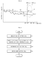
- FIG. 3 is a graph illustrating the SOC of each of the plurality of battery cells which is measured by the MCU of FIG. 2 .
- the graph shows the SOC of a battery cell over a period of time
- B1, B2 and B3 represent a plurality of battery cells.
- B1 may represent a first battery cell
- B2 may represent a second battery cell
- B3 may represent a third battery cell.
- a region “a” shows that the first difference value "
- the region “a” shows that the second difference value "
- the MCU 20 can detect a short battery cell capable of causing or having caused short during the parking period of a vehicle among the plurality of battery cells through Equation (1) or Equation (2).
- FIG. 4 is a flow chart illustrating a driving method of a battery management system according to an embodiment.
- FIG. 5A is a flow chart for describing an example of an operation for comparing the SOC difference value of a battery cell and a reference value in FIG. 4 .
- FIG. 5B is a flow chart for describing another example of an operation for comparing the SOC difference value of the battery cell and the reference value in FIG. 4 .
- a driving method of a battery management system includes operation S1 of measuring the SOC of a battery cell, operation S2 of comparing the SOC difference value of a battery cell and a reference value, operation S3 of determining a short battery cell, and operation S4 of informing the short battery cell.
- the SOC measurement unit 22 of the MCU 20 calculates the OCV of each battery cell by using the cell voltage and cell current of each battery cell that are inputted from the sensing unit 10 through the controller 21, and may measure the SOC of each battery cell with the OCV.
- the SOC measurement unit 22 measures the first SOC of each battery cell, which is used for detecting a short battery cell capable of causing or having caused short during a parking period among the plurality of battery cells, in a key-off state, and measures the second SOC of the battery cell in a key-on state after the key-off state and transmits the measured SOC.
- the first SOC and second SOC of each battery cell are stored in the data storage 23 through the controller 21.
- the timer 24 of the MCU 20 measures a key-off time and a key-on time.
- the key-off time and the key-on time are stored in the data storage 23. Accordingly, the controller 21 may check the parking period of a vehicle with the key-off time and the key-on time.
- the controller 21 performs operation S21 of comparing whether the first difference value "
- the first and second reference values REF1 and REF2 are differently set according to the parking period of the vehicle and are stored in the data storage 23. Therefore, the controller 21 performs operation S2 of comparing the SOC difference value of a battery cell and a reference value by using the first and second reference values REF1 and REF2 in accordance with the parking period of the vehicle that are stored in the data storage 23.
- operation S21 may be first performed.
- operation S3 of determining a short battery cell is immediately performed, and when the first difference value "
- performing operation S3 of determining a short battery cell denotes that a short battery cell capable of causing or having caused short during a parking period among the plurality of battery cells is detected
- performing operation S22 denotes that a short battery cell is detected in another scheme because the short battery cell is not detected through operation S21.
- the driving method of a battery management system is again performed from operation S1 of measuring the SOC of a battery cell.
- operation S1 of measuring the SOC of a battery cell is again performed, this denotes that short does not currently occur in a plurality of battery cells.
- operation S22 may be first performed.
- operation S3 of determining a short battery cell is immediately performed, and when the second difference value "SOC2_max - SOC2_n" is less than the second reference value REF2, operation S21 is performed.
- performing operation S3 of determining a short battery cell denotes that a short battery cell capable of causing or having caused short during a parking period among the plurality of battery cells is detected
- performing operation S21 denotes that a short battery cell is detected in another scheme because the short battery cell is not detected through operation S22.
- operation S3 of determining a short battery cell is performed, and when the first difference value "
- operation S1 of measuring the SOC of a battery cell is again performed, this denotes that short does not currently occur in a plurality of battery cells.
- operation S21 may be first performed or operation S22 may be first performed. This may be determined according to the setting of the controller 21.
- the controller 21 may determine a battery cell in which the first difference value "
- the MCU 20 transmits information of a short battery cell capable of causing or having caused short during a parking period to the ECU 7, thereby allowing the information to be displayed on a display device. Then, a user can check whether a short battery cell is detected or not.
- the battery management system and the driving method thereof detect a short battery cell capable of causing or having caused short during a parking period among the plurality of battery cells by using the SOC of the battery cell before and after parking, and inform a user of the short battery cell, thereby enabling the user to check the short battery cell.
- the battery management system and the driving method thereof enable to change the short battery cell, and thus can prevent the vehicle from exploding due to the short caused by the short battery cell.
Landscapes
- General Physics & Mathematics (AREA)
- Physics & Mathematics (AREA)
- Engineering & Computer Science (AREA)
- Chemical & Material Sciences (AREA)
- Electrochemistry (AREA)
- Chemical Kinetics & Catalysis (AREA)
- Manufacturing & Machinery (AREA)
- General Chemical & Material Sciences (AREA)
- Computer Hardware Design (AREA)
- Microelectronics & Electronic Packaging (AREA)
- Combustion & Propulsion (AREA)
- Secondary Cells (AREA)
- Charge And Discharge Circuits For Batteries Or The Like (AREA)
- Electric Propulsion And Braking For Vehicles (AREA)
- Tests Of Electric Status Of Batteries (AREA)
Applications Claiming Priority (1)
| Application Number | Priority Date | Filing Date | Title |
|---|---|---|---|
| KR1020100007050A KR101057547B1 (ko) | 2010-01-26 | 2010-01-26 | 배터리 관리 시스템 및 그 구동 방법 |
Publications (2)
| Publication Number | Publication Date |
|---|---|
| EP2360485A1 true EP2360485A1 (fr) | 2011-08-24 |
| EP2360485B1 EP2360485B1 (fr) | 2013-01-16 |
Family
ID=43383005
Family Applications (1)
| Application Number | Title | Priority Date | Filing Date |
|---|---|---|---|
| EP10189941A Active EP2360485B1 (fr) | 2010-01-26 | 2010-11-04 | Système de gestion de batterie et son procédé de commande |
Country Status (5)
| Country | Link |
|---|---|
| US (1) | US8463563B2 (fr) |
| EP (1) | EP2360485B1 (fr) |
| JP (1) | JP4979795B2 (fr) |
| KR (1) | KR101057547B1 (fr) |
| CN (1) | CN102136744B (fr) |
Cited By (1)
| Publication number | Priority date | Publication date | Assignee | Title |
|---|---|---|---|---|
| US10336209B2 (en) | 2014-01-22 | 2019-07-02 | Robert Bosch Gmbh | Method and device for operating a battery, in particular a lithium ion battery, in a consumer |
Families Citing this family (40)
| Publication number | Priority date | Publication date | Assignee | Title |
|---|---|---|---|---|
| KR101057542B1 (ko) * | 2010-01-26 | 2011-08-17 | 에스비리모티브 주식회사 | 배터리 관리 시스템 및 그 구동 방법 |
| KR101255248B1 (ko) * | 2011-07-04 | 2013-04-16 | 로베르트 보쉬 게엠베하 | 배터리 관리 시스템 및 이의 제어 방법 |
| DE102011079291A1 (de) * | 2011-07-18 | 2013-01-24 | Sb Limotive Company Ltd. | Batteriemanagementsystem und Verfahren zur Bestimmung der Ladezustände von Batteriezellen, Batterie und Kraftfahrzeug mit Batteriemanagementsystem |
| DE102012202863A1 (de) * | 2012-02-24 | 2013-08-29 | Robert Bosch Gmbh | System und Verfahren zum Ansteuern einer Energiespeichereinrichtung |
| FR2989779B1 (fr) * | 2012-04-19 | 2015-02-06 | Commissariat Energie Atomique | Dispositif de determination d'une caracteristique d'une batterie et procede de fonctionnement d'un tel dispositif |
| CN104487857B (zh) * | 2012-07-27 | 2017-03-08 | 丰田自动车株式会社 | 二次电池的短路检查方法 |
| KR101488357B1 (ko) * | 2013-05-10 | 2015-01-30 | (주)종합시스템 | 스마트 배터리 관리 시스템 |
| DE102013214817A1 (de) * | 2013-07-30 | 2015-02-05 | Robert Bosch Gmbh | Verfahren zur Diagnose eines Zustands einer Batterie |
| CN103558462B (zh) * | 2013-09-30 | 2015-11-18 | 广东电网公司电力科学研究院 | 检测电池管理系统的装置和方法 |
| US9878631B2 (en) | 2014-02-25 | 2018-01-30 | Elwha Llc | System and method for predictive control of an energy storage system for a vehicle |
| US9056556B1 (en) | 2014-02-25 | 2015-06-16 | Elwha Llc | System and method for configuration and management of an energy storage system for a vehicle |
| US9079505B1 (en) | 2014-02-25 | 2015-07-14 | Elwah LLC | System and method for management of a fleet of vehicles having an energy storage system |
| US9431837B2 (en) * | 2014-04-30 | 2016-08-30 | Johnson Controls Technology Company | Integrated battery management system and method |
| CN104020380B (zh) * | 2014-06-18 | 2017-07-11 | 重庆大学 | 不同温度及气体中气固表面聚积电荷模拟实验系统和方法 |
| CN104835987B (zh) * | 2014-07-25 | 2017-08-04 | 北汽福田汽车股份有限公司 | 用于电池系统的电池预处理方法 |
| US10033213B2 (en) * | 2014-09-30 | 2018-07-24 | Johnson Controls Technology Company | Short circuit wake-up system and method for automotive battery while in key-off position |
| CN104577242B (zh) * | 2014-12-30 | 2017-06-06 | 中智科创机器人有限公司 | 一种电池组管理系统和方法 |
| KR102372818B1 (ko) * | 2014-12-30 | 2022-03-11 | 에이치그린파워 주식회사 | 과충전 방지 장치 및 방법 |
| KR102377394B1 (ko) * | 2015-05-14 | 2022-03-22 | 삼성에스디아이 주식회사 | 에너지 저장 시스템 및 그 구동 방법 |
| US10749362B2 (en) * | 2015-08-28 | 2020-08-18 | Panasonic Intellectual Property Management Co., Ltd. | Method for server apparatus to detect abnormality in electrical-power storage device |
| EP3408916B1 (fr) * | 2016-01-29 | 2022-07-06 | Form Energy, Inc. | Adressage automatique des noeuds de batterie dans un système de batterie |
| CN105790224B (zh) * | 2016-04-18 | 2018-09-14 | 深圳市智锂能源科技有限公司 | 一种电动车动力电池二次保护系统及方法 |
| KR102145524B1 (ko) * | 2016-06-22 | 2020-08-18 | 주식회사 엘지화학 | 전기 자동차용 구동 회로 및 그 제어 방법 |
| KR20180024248A (ko) * | 2016-08-29 | 2018-03-08 | 삼성전자주식회사 | 돌입 전류를 방지하기 위한 프리차지 회로 및 이를 포함하는 전자 장치 |
| CN107870301B (zh) * | 2016-09-27 | 2020-09-04 | 华为技术有限公司 | 一种电池微短路的检测方法及装置 |
| US10690704B2 (en) * | 2017-05-18 | 2020-06-23 | I.D. Systems, Inc. | Multi-access control and multi-relay systems and methods |
| KR102308299B1 (ko) * | 2017-11-06 | 2021-10-01 | 주식회사 엘지에너지솔루션 | 셀 모듈 균등화 및 프리차지 장치 및 방법 |
| JP6965830B2 (ja) * | 2018-05-24 | 2021-11-10 | トヨタ自動車株式会社 | 車両用電源装置 |
| US10960776B2 (en) | 2018-08-17 | 2021-03-30 | Zoox, Inc. | Redundant battery management system architecture |
| KR102424295B1 (ko) * | 2018-09-27 | 2022-07-21 | 주식회사 엘지에너지솔루션 | Soc 추정 장치 및 방법 |
| CN109638387B (zh) * | 2018-11-30 | 2020-09-15 | 北京汽车股份有限公司 | 一种动力电池加热系统和加热控制方法及车辆 |
| CN109787313A (zh) * | 2019-01-31 | 2019-05-21 | 欣旺达电子股份有限公司 | 基于锂电池的数据中心高压直流备份电源 |
| WO2020195192A1 (fr) * | 2019-03-26 | 2020-10-01 | 日立オートモティブシステムズ株式会社 | Dispositif de commande électronique et procédé de diagnostic pour dispositif de commande électronique |
| JP7309269B2 (ja) * | 2019-04-15 | 2023-07-18 | ダイハツ工業株式会社 | 車両制御装置 |
| KR20210004646A (ko) * | 2019-07-05 | 2021-01-13 | 주식회사 엘지화학 | 배터리 셀 진단 장치 및 방법 |
| CN111146511B (zh) * | 2019-12-03 | 2023-05-30 | 深圳市科陆电子科技股份有限公司 | Bms电池soc修正维护方法及系统 |
| KR20210130874A (ko) * | 2020-04-22 | 2021-11-02 | 주식회사 엘지에너지솔루션 | 저전압 셀 검출 방법 및 그 방법을 제공하는 배터리 관리 시스템 |
| KR20220167847A (ko) * | 2021-06-14 | 2022-12-22 | 주식회사 엘지에너지솔루션 | 배터리 관리 시스템, 배터리 팩, 전기 차량 및 배터리 관리 방법 |
| CN114859258B (zh) * | 2022-07-06 | 2022-12-20 | 荣耀终端有限公司 | 应用于多电池的电量计和电子设备 |
| CN115497192B (zh) * | 2022-09-26 | 2023-08-25 | 深蓝汽车科技有限公司 | 一种车辆的驻车时间获取方法、装置、设备及存储介质 |
Citations (4)
| Publication number | Priority date | Publication date | Assignee | Title |
|---|---|---|---|---|
| US20080036421A1 (en) * | 2006-08-11 | 2008-02-14 | Samsung Sdi Co., Ltd. | Battery management system and driving method thereof |
| US20080091362A1 (en) * | 2006-10-16 | 2008-04-17 | Samsung Sdi Co., Ltd. | Battery management system and driving method thereof |
| US20090099799A1 (en) * | 2007-10-10 | 2009-04-16 | Texas Instruments Incorporated | Systems, Methods and Circuits for Determining Micro-Short |
| WO2009119271A1 (fr) * | 2008-03-25 | 2009-10-01 | Kabushiki Kaisha Toshiba | Procédé de charge d'un élément assemblé et système d’élément assemblé |
Family Cites Families (14)
| Publication number | Priority date | Publication date | Assignee | Title |
|---|---|---|---|---|
| JP3654058B2 (ja) * | 1999-06-25 | 2005-06-02 | トヨタ自動車株式会社 | 電池検査装置 |
| KR20020054779A (ko) | 2000-12-28 | 2002-07-08 | 이계안 | 전기 자동차용 배터리의 오류 진단방법 |
| KR100387491B1 (ko) * | 2000-12-28 | 2003-06-18 | 현대자동차주식회사 | 전기 자동차의 배터리 고장 진단방법 |
| JP3839761B2 (ja) * | 2001-09-14 | 2006-11-01 | 松下電器産業株式会社 | バッテリ制御装置 |
| JP2003338325A (ja) * | 2002-05-21 | 2003-11-28 | Matsushita Electric Ind Co Ltd | 蓄電池の劣化状態判定方法およびそれを用いた蓄電池の充電方法 |
| JP2005261072A (ja) * | 2004-03-11 | 2005-09-22 | Yazaki Corp | バッテリの充電制御方法および装置 |
| JP2006337155A (ja) | 2005-06-01 | 2006-12-14 | Matsushita Electric Ind Co Ltd | 電池監視装置 |
| KR100766982B1 (ko) * | 2006-09-05 | 2007-10-15 | 삼성에스디아이 주식회사 | 배터리 관리 시스템 및 그의 구동 방법 |
| JP2008069691A (ja) | 2006-09-13 | 2008-03-27 | Ohatsu Co Ltd | 発電用風車装置および風力発電装置 |
| KR100839382B1 (ko) * | 2006-10-16 | 2008-06-20 | 삼성에스디아이 주식회사 | 배터리 관리 시스템 및 그의 구동 방법 |
| JP5127383B2 (ja) * | 2007-09-28 | 2013-01-23 | 株式会社日立製作所 | 電池用集積回路および該電池用集積回路を使用した車両用電源システム |
| JP2009252459A (ja) * | 2008-04-03 | 2009-10-29 | Panasonic Corp | アルカリ蓄電池の検査方法 |
| US8170737B2 (en) * | 2009-04-30 | 2012-05-01 | GM Global Technology Operations LLC | Method of controlling vehicle powertrain and vehicle control system |
| KR101057542B1 (ko) * | 2010-01-26 | 2011-08-17 | 에스비리모티브 주식회사 | 배터리 관리 시스템 및 그 구동 방법 |
-
2010
- 2010-01-26 KR KR1020100007050A patent/KR101057547B1/ko active IP Right Grant
- 2010-06-09 JP JP2010132387A patent/JP4979795B2/ja active Active
- 2010-06-17 US US12/817,381 patent/US8463563B2/en active Active
- 2010-11-04 EP EP10189941A patent/EP2360485B1/fr active Active
-
2011
- 2011-01-11 CN CN2011100098078A patent/CN102136744B/zh active Active
Patent Citations (4)
| Publication number | Priority date | Publication date | Assignee | Title |
|---|---|---|---|---|
| US20080036421A1 (en) * | 2006-08-11 | 2008-02-14 | Samsung Sdi Co., Ltd. | Battery management system and driving method thereof |
| US20080091362A1 (en) * | 2006-10-16 | 2008-04-17 | Samsung Sdi Co., Ltd. | Battery management system and driving method thereof |
| US20090099799A1 (en) * | 2007-10-10 | 2009-04-16 | Texas Instruments Incorporated | Systems, Methods and Circuits for Determining Micro-Short |
| WO2009119271A1 (fr) * | 2008-03-25 | 2009-10-01 | Kabushiki Kaisha Toshiba | Procédé de charge d'un élément assemblé et système d’élément assemblé |
Cited By (1)
| Publication number | Priority date | Publication date | Assignee | Title |
|---|---|---|---|---|
| US10336209B2 (en) | 2014-01-22 | 2019-07-02 | Robert Bosch Gmbh | Method and device for operating a battery, in particular a lithium ion battery, in a consumer |
Also Published As
| Publication number | Publication date |
|---|---|
| US20110184677A1 (en) | 2011-07-28 |
| US8463563B2 (en) | 2013-06-11 |
| JP2011154016A (ja) | 2011-08-11 |
| EP2360485B1 (fr) | 2013-01-16 |
| CN102136744B (zh) | 2013-12-25 |
| CN102136744A (zh) | 2011-07-27 |
| KR101057547B1 (ko) | 2011-08-17 |
| KR20110087569A (ko) | 2011-08-03 |
| JP4979795B2 (ja) | 2012-07-18 |
Similar Documents
| Publication | Publication Date | Title |
|---|---|---|
| EP2360485B1 (fr) | Système de gestion de batterie et son procédé de commande | |
| US8264201B2 (en) | Battery management system and driving method thereof | |
| US7902829B2 (en) | Battery management system and driving method thereof | |
| KR101030910B1 (ko) | 배터리 관리 시스템 및 그 구동 방법 | |
| US8669741B2 (en) | Battery management system and driving method thereof | |
| JP4597501B2 (ja) | 二次電池の残存容量推定方法および装置 | |
| US7548821B2 (en) | Battery management system and driving method thereof | |
| US8405352B2 (en) | Battery management system and battery management method | |
| KR101041124B1 (ko) | 배터리 관리 시스템 및 그 구동 방법 | |
| JP5159498B2 (ja) | ハイブリッドカーの電源装置における電池の充放電制御方法 | |
| US20080100265A1 (en) | Battery management system and driving method thereof | |
| KR101552903B1 (ko) | 배터리 관리 시스템 및 방법 | |
| KR101073277B1 (ko) | 하이브리드 전기 자동차용 배터리 팩의 셀 밸런싱 방법 및이를 위한 장치 |
Legal Events
| Date | Code | Title | Description |
|---|---|---|---|
| PUAI | Public reference made under article 153(3) epc to a published international application that has entered the european phase |
Free format text: ORIGINAL CODE: 0009012 |
|
| 17P | Request for examination filed |
Effective date: 20101104 |
|
| AK | Designated contracting states |
Kind code of ref document: A1 Designated state(s): AL AT BE BG CH CY CZ DE DK EE ES FI FR GB GR HR HU IE IS IT LI LT LU LV MC MK MT NL NO PL PT RO RS SE SI SK SM TR |
|
| AX | Request for extension of the european patent |
Extension state: BA ME |
|
| GRAP | Despatch of communication of intention to grant a patent |
Free format text: ORIGINAL CODE: EPIDOSNIGR1 |
|
| RIC1 | Information provided on ipc code assigned before grant |
Ipc: G01R 31/00 20060101AFI20120614BHEP Ipc: G01R 31/36 20060101ALI20120614BHEP |
|
| GRAS | Grant fee paid |
Free format text: ORIGINAL CODE: EPIDOSNIGR3 |
|
| GRAA | (expected) grant |
Free format text: ORIGINAL CODE: 0009210 |
|
| AK | Designated contracting states |
Kind code of ref document: B1 Designated state(s): AL AT BE BG CH CY CZ DE DK EE ES FI FR GB GR HR HU IE IS IT LI LT LU LV MC MK MT NL NO PL PT RO RS SE SI SK SM TR |
|
| REG | Reference to a national code |
Ref country code: GB Ref legal event code: FG4D |
|
| REG | Reference to a national code |
Ref country code: CH Ref legal event code: EP |
|
| REG | Reference to a national code |
Ref country code: IE Ref legal event code: FG4D |
|
| REG | Reference to a national code |
Ref country code: AT Ref legal event code: REF Ref document number: 594142 Country of ref document: AT Kind code of ref document: T Effective date: 20130215 Ref country code: CH Ref legal event code: EP |
|
| REG | Reference to a national code |
Ref country code: DE Ref legal event code: R096 Ref document number: 602010004607 Country of ref document: DE Effective date: 20130314 |
|
| REG | Reference to a national code |
Ref country code: FR Ref legal event code: TQ Owner name: SAMSUNG SDI CO., LTD., KR Effective date: 20130218 Ref country code: FR Ref legal event code: TQ Owner name: ROBERT BOSCH GMBH, DE Effective date: 20130218 |
|
| REG | Reference to a national code |
Ref country code: DE Ref legal event code: R081 Ref document number: 602010004607 Country of ref document: DE Owner name: ROBERT BOSCH GMBH, DE Free format text: FORMER OWNER: SB LIMOTIVE CO., LTD., YONGIN, KR Effective date: 20130312 Ref country code: DE Ref legal event code: R081 Ref document number: 602010004607 Country of ref document: DE Owner name: SAMSUNG SDI CO., LTD., KR Free format text: FORMER OWNER: SB LIMOTIVE CO., LTD., YONGIN, KR Effective date: 20130312 Ref country code: DE Ref legal event code: R081 Ref document number: 602010004607 Country of ref document: DE Owner name: ROBERT BOSCH GMBH, DE Free format text: FORMER OWNER: SB LIMOTIVE CO., LTD., YONGIN, KYONGGI, KR Effective date: 20130312 Ref country code: DE Ref legal event code: R081 Ref document number: 602010004607 Country of ref document: DE Owner name: SAMSUNG SDI CO., LTD., YONGIN, KR Free format text: FORMER OWNER: SB LIMOTIVE CO., LTD., YONGIN, KYONGGI, KR Effective date: 20130312 |
|
| REG | Reference to a national code |
Ref country code: GB Ref legal event code: 732E Free format text: REGISTERED BETWEEN 20130425 AND 20130501 |
|
| REG | Reference to a national code |
Ref country code: AT Ref legal event code: MK05 Ref document number: 594142 Country of ref document: AT Kind code of ref document: T Effective date: 20130116 |
|
| REG | Reference to a national code |
Ref country code: NL Ref legal event code: VDEP Effective date: 20130116 |
|
| REG | Reference to a national code |
Ref country code: LT Ref legal event code: MG4D |
|
| PG25 | Lapsed in a contracting state [announced via postgrant information from national office to epo] |
Ref country code: SE Free format text: LAPSE BECAUSE OF FAILURE TO SUBMIT A TRANSLATION OF THE DESCRIPTION OR TO PAY THE FEE WITHIN THE PRESCRIBED TIME-LIMIT Effective date: 20130116 Ref country code: BG Free format text: LAPSE BECAUSE OF FAILURE TO SUBMIT A TRANSLATION OF THE DESCRIPTION OR TO PAY THE FEE WITHIN THE PRESCRIBED TIME-LIMIT Effective date: 20130416 Ref country code: AT Free format text: LAPSE BECAUSE OF FAILURE TO SUBMIT A TRANSLATION OF THE DESCRIPTION OR TO PAY THE FEE WITHIN THE PRESCRIBED TIME-LIMIT Effective date: 20130116 Ref country code: ES Free format text: LAPSE BECAUSE OF FAILURE TO SUBMIT A TRANSLATION OF THE DESCRIPTION OR TO PAY THE FEE WITHIN THE PRESCRIBED TIME-LIMIT Effective date: 20130427 Ref country code: BE Free format text: LAPSE BECAUSE OF FAILURE TO SUBMIT A TRANSLATION OF THE DESCRIPTION OR TO PAY THE FEE WITHIN THE PRESCRIBED TIME-LIMIT Effective date: 20130116 Ref country code: NO Free format text: LAPSE BECAUSE OF FAILURE TO SUBMIT A TRANSLATION OF THE DESCRIPTION OR TO PAY THE FEE WITHIN THE PRESCRIBED TIME-LIMIT Effective date: 20130416 Ref country code: LT Free format text: LAPSE BECAUSE OF FAILURE TO SUBMIT A TRANSLATION OF THE DESCRIPTION OR TO PAY THE FEE WITHIN THE PRESCRIBED TIME-LIMIT Effective date: 20130116 Ref country code: IS Free format text: LAPSE BECAUSE OF FAILURE TO SUBMIT A TRANSLATION OF THE DESCRIPTION OR TO PAY THE FEE WITHIN THE PRESCRIBED TIME-LIMIT Effective date: 20130516 |
|
| PG25 | Lapsed in a contracting state [announced via postgrant information from national office to epo] |
Ref country code: LV Free format text: LAPSE BECAUSE OF FAILURE TO SUBMIT A TRANSLATION OF THE DESCRIPTION OR TO PAY THE FEE WITHIN THE PRESCRIBED TIME-LIMIT Effective date: 20130116 Ref country code: SI Free format text: LAPSE BECAUSE OF FAILURE TO SUBMIT A TRANSLATION OF THE DESCRIPTION OR TO PAY THE FEE WITHIN THE PRESCRIBED TIME-LIMIT Effective date: 20130116 Ref country code: NL Free format text: LAPSE BECAUSE OF FAILURE TO SUBMIT A TRANSLATION OF THE DESCRIPTION OR TO PAY THE FEE WITHIN THE PRESCRIBED TIME-LIMIT Effective date: 20130116 Ref country code: GR Free format text: LAPSE BECAUSE OF FAILURE TO SUBMIT A TRANSLATION OF THE DESCRIPTION OR TO PAY THE FEE WITHIN THE PRESCRIBED TIME-LIMIT Effective date: 20130417 Ref country code: FI Free format text: LAPSE BECAUSE OF FAILURE TO SUBMIT A TRANSLATION OF THE DESCRIPTION OR TO PAY THE FEE WITHIN THE PRESCRIBED TIME-LIMIT Effective date: 20130116 Ref country code: PT Free format text: LAPSE BECAUSE OF FAILURE TO SUBMIT A TRANSLATION OF THE DESCRIPTION OR TO PAY THE FEE WITHIN THE PRESCRIBED TIME-LIMIT Effective date: 20130516 Ref country code: PL Free format text: LAPSE BECAUSE OF FAILURE TO SUBMIT A TRANSLATION OF THE DESCRIPTION OR TO PAY THE FEE WITHIN THE PRESCRIBED TIME-LIMIT Effective date: 20130116 |
|
| PG25 | Lapsed in a contracting state [announced via postgrant information from national office to epo] |
Ref country code: RS Free format text: LAPSE BECAUSE OF FAILURE TO SUBMIT A TRANSLATION OF THE DESCRIPTION OR TO PAY THE FEE WITHIN THE PRESCRIBED TIME-LIMIT Effective date: 20130116 Ref country code: HR Free format text: LAPSE BECAUSE OF FAILURE TO SUBMIT A TRANSLATION OF THE DESCRIPTION OR TO PAY THE FEE WITHIN THE PRESCRIBED TIME-LIMIT Effective date: 20130116 |
|
| PG25 | Lapsed in a contracting state [announced via postgrant information from national office to epo] |
Ref country code: DK Free format text: LAPSE BECAUSE OF FAILURE TO SUBMIT A TRANSLATION OF THE DESCRIPTION OR TO PAY THE FEE WITHIN THE PRESCRIBED TIME-LIMIT Effective date: 20130116 Ref country code: CZ Free format text: LAPSE BECAUSE OF FAILURE TO SUBMIT A TRANSLATION OF THE DESCRIPTION OR TO PAY THE FEE WITHIN THE PRESCRIBED TIME-LIMIT Effective date: 20130116 Ref country code: RO Free format text: LAPSE BECAUSE OF FAILURE TO SUBMIT A TRANSLATION OF THE DESCRIPTION OR TO PAY THE FEE WITHIN THE PRESCRIBED TIME-LIMIT Effective date: 20130116 Ref country code: SK Free format text: LAPSE BECAUSE OF FAILURE TO SUBMIT A TRANSLATION OF THE DESCRIPTION OR TO PAY THE FEE WITHIN THE PRESCRIBED TIME-LIMIT Effective date: 20130116 Ref country code: EE Free format text: LAPSE BECAUSE OF FAILURE TO SUBMIT A TRANSLATION OF THE DESCRIPTION OR TO PAY THE FEE WITHIN THE PRESCRIBED TIME-LIMIT Effective date: 20130116 |
|
| PLBE | No opposition filed within time limit |
Free format text: ORIGINAL CODE: 0009261 |
|
| STAA | Information on the status of an ep patent application or granted ep patent |
Free format text: STATUS: NO OPPOSITION FILED WITHIN TIME LIMIT |
|
| PG25 | Lapsed in a contracting state [announced via postgrant information from national office to epo] |
Ref country code: CY Free format text: LAPSE BECAUSE OF FAILURE TO SUBMIT A TRANSLATION OF THE DESCRIPTION OR TO PAY THE FEE WITHIN THE PRESCRIBED TIME-LIMIT Effective date: 20130116 |
|
| 26N | No opposition filed |
Effective date: 20131017 |
|
| PG25 | Lapsed in a contracting state [announced via postgrant information from national office to epo] |
Ref country code: IT Free format text: LAPSE BECAUSE OF FAILURE TO SUBMIT A TRANSLATION OF THE DESCRIPTION OR TO PAY THE FEE WITHIN THE PRESCRIBED TIME-LIMIT Effective date: 20130116 |
|
| REG | Reference to a national code |
Ref country code: DE Ref legal event code: R097 Ref document number: 602010004607 Country of ref document: DE Effective date: 20131017 |
|
| PG25 | Lapsed in a contracting state [announced via postgrant information from national office to epo] |
Ref country code: MC Free format text: LAPSE BECAUSE OF FAILURE TO SUBMIT A TRANSLATION OF THE DESCRIPTION OR TO PAY THE FEE WITHIN THE PRESCRIBED TIME-LIMIT Effective date: 20130116 |
|
| REG | Reference to a national code |
Ref country code: IE Ref legal event code: MM4A |
|
| PG25 | Lapsed in a contracting state [announced via postgrant information from national office to epo] |
Ref country code: IE Free format text: LAPSE BECAUSE OF NON-PAYMENT OF DUE FEES Effective date: 20131104 |
|
| PG25 | Lapsed in a contracting state [announced via postgrant information from national office to epo] |
Ref country code: SM Free format text: LAPSE BECAUSE OF FAILURE TO SUBMIT A TRANSLATION OF THE DESCRIPTION OR TO PAY THE FEE WITHIN THE PRESCRIBED TIME-LIMIT Effective date: 20130116 |
|
| PG25 | Lapsed in a contracting state [announced via postgrant information from national office to epo] |
Ref country code: TR Free format text: LAPSE BECAUSE OF FAILURE TO SUBMIT A TRANSLATION OF THE DESCRIPTION OR TO PAY THE FEE WITHIN THE PRESCRIBED TIME-LIMIT Effective date: 20130116 |
|
| REG | Reference to a national code |
Ref country code: CH Ref legal event code: PL |
|
| PG25 | Lapsed in a contracting state [announced via postgrant information from national office to epo] |
Ref country code: HU Free format text: LAPSE BECAUSE OF FAILURE TO SUBMIT A TRANSLATION OF THE DESCRIPTION OR TO PAY THE FEE WITHIN THE PRESCRIBED TIME-LIMIT; INVALID AB INITIO Effective date: 20101104 Ref country code: MK Free format text: LAPSE BECAUSE OF FAILURE TO SUBMIT A TRANSLATION OF THE DESCRIPTION OR TO PAY THE FEE WITHIN THE PRESCRIBED TIME-LIMIT Effective date: 20130116 Ref country code: LI Free format text: LAPSE BECAUSE OF NON-PAYMENT OF DUE FEES Effective date: 20141130 Ref country code: LU Free format text: LAPSE BECAUSE OF NON-PAYMENT OF DUE FEES Effective date: 20131104 Ref country code: CH Free format text: LAPSE BECAUSE OF NON-PAYMENT OF DUE FEES Effective date: 20141130 |
|
| PG25 | Lapsed in a contracting state [announced via postgrant information from national office to epo] |
Ref country code: MT Free format text: LAPSE BECAUSE OF FAILURE TO SUBMIT A TRANSLATION OF THE DESCRIPTION OR TO PAY THE FEE WITHIN THE PRESCRIBED TIME-LIMIT Effective date: 20130116 |
|
| REG | Reference to a national code |
Ref country code: FR Ref legal event code: PLFP Year of fee payment: 6 |
|
| REG | Reference to a national code |
Ref country code: FR Ref legal event code: PLFP Year of fee payment: 7 |
|
| REG | Reference to a national code |
Ref country code: FR Ref legal event code: PLFP Year of fee payment: 8 |
|
| REG | Reference to a national code |
Ref country code: FR Ref legal event code: PLFP Year of fee payment: 9 |
|
| PG25 | Lapsed in a contracting state [announced via postgrant information from national office to epo] |
Ref country code: AL Free format text: LAPSE BECAUSE OF FAILURE TO SUBMIT A TRANSLATION OF THE DESCRIPTION OR TO PAY THE FEE WITHIN THE PRESCRIBED TIME-LIMIT Effective date: 20130116 |
|
| P01 | Opt-out of the competence of the unified patent court (upc) registered |
Effective date: 20230528 |
|
| PGFP | Annual fee paid to national office [announced via postgrant information from national office to epo] |
Ref country code: GB Payment date: 20231102 Year of fee payment: 14 |
|
| PGFP | Annual fee paid to national office [announced via postgrant information from national office to epo] |
Ref country code: FR Payment date: 20231108 Year of fee payment: 14 Ref country code: DE Payment date: 20231031 Year of fee payment: 14 |