EP2359677A2 - Montagebauteil zur Befestigung eines Erntegutbehandlungselementes an einem Abscheiderotor - Google Patents
Montagebauteil zur Befestigung eines Erntegutbehandlungselementes an einem Abscheiderotor Download PDFInfo
- Publication number
- EP2359677A2 EP2359677A2 EP10192308A EP10192308A EP2359677A2 EP 2359677 A2 EP2359677 A2 EP 2359677A2 EP 10192308 A EP10192308 A EP 10192308A EP 10192308 A EP10192308 A EP 10192308A EP 2359677 A2 EP2359677 A2 EP 2359677A2
- Authority
- EP
- European Patent Office
- Prior art keywords
- component
- mounting
- side walls
- side wall
- rotor
- Prior art date
- Legal status (The legal status is an assumption and is not a legal conclusion. Google has not performed a legal analysis and makes no representation as to the accuracy of the status listed.)
- Granted
Links
Images
Classifications
-
- A—HUMAN NECESSITIES
- A01—AGRICULTURE; FORESTRY; ANIMAL HUSBANDRY; HUNTING; TRAPPING; FISHING
- A01F—PROCESSING OF HARVESTED PRODUCE; HAY OR STRAW PRESSES; DEVICES FOR STORING AGRICULTURAL OR HORTICULTURAL PRODUCE
- A01F7/00—Threshing apparatus
- A01F7/02—Threshing apparatus with rotating tools
- A01F7/06—Threshing apparatus with rotating tools with axles in line with the feeding direction ; Axial threshing machines
-
- A—HUMAN NECESSITIES
- A01—AGRICULTURE; FORESTRY; ANIMAL HUSBANDRY; HUNTING; TRAPPING; FISHING
- A01F—PROCESSING OF HARVESTED PRODUCE; HAY OR STRAW PRESSES; DEVICES FOR STORING AGRICULTURAL OR HORTICULTURAL PRODUCE
- A01F12/00—Parts or details of threshing apparatus
- A01F12/18—Threshing devices
- A01F12/22—Threshing cylinders with teeth
Definitions
- the mounting component for fixing a threshing element to an axial threshing separator rotor known.
- the mounting component on which the threshing element is detachably arranged, is designed as a profiled component with sections of walls extending in sections in the circumferential direction of the separating motor and parallel to each other.
- the side walls of the mounting component have wing-like, parallel to the lateral surface of the threshing separator rotor sections, with which the mounting member is connected to the threshing separator rotor by spot welding.
- the L-shaped threshing member is applied, which is directly exposed to the crop stream to be processed.
- a disadvantage of the mounting component according to the US 5,192,245 proves that with increasing radial extent of the mounting member and / or arranged thereon Dreschettis to the lateral surface of the Abscheiderotors on this acting forces due to the unfavorable lever ratio are larger, so that a secure hold of welded to the outer surface of the Abscheiderotors mounting component can not be guaranteed.
- the detachment of the mounting component of the lateral surface leads to severe damage of the separator rotor, which adversely affect its performance.
- Object of the present invention is therefore to develop a mounting component of the type mentioned in such a way that a higher service life of the separator and a higher load capacity of the mounting components and arranged thereon Erntegut adaptsijns is achieved.
- each of the side walls of the carrier element has a longitudinal weld extending substantially parallel thereto with a weld section extending beyond the length of the respective side wall.
- the weld seam section of the longitudinal weld seam extending beyond the length of the respective side wall should preferably extend in the direction of rotation of the separator rotor.
- the torque to be absorbed by the mounting element during operation of the separator rotor, which is applied to the mounting element via the crop coming into contact with the crop treatment element, is introduced into the weld seam sections which are extended in the direction of force application, whereby the voltage peaks be reduced in the base region of the mounting element, the transition region from the mounting element to the lateral surface of the separator rotor.
- the mounting component can be designed as a U-profile.
- the side walls of the mounting member may be adapted on its the surface of the separator rotor side facing the cylindrical contour of the separator rotor.
- the side walls may have a recess.
- the recess in the side walls may serve to achieve yielding of the mounting element in the direction of rotation of the separator rotor in the event of an impact load of the crop treatment element occurring in order to prevent the mounting element from tearing off the jacket surface of the separator rotor, which may render the separator rotor unusable.
- the buckled mounting element is interchangeable in a comparatively simple manner.
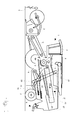
- FIG. 1 schematically illustrated combine harvester 1 with an axial separator 2 consists essentially of a cutting unit 3, a threshing device 4, a cleaning device 5, a grain tank 6, a cab 7 and from the axial separator 2 downstream straw chopper. 8
- the crop 9 cut off by the cutting unit 3 passes via a sloping conveyor channel 10 to a threshing device 4 operating on the tangential principle.
- a threshing device 4 operating on the tangential principle.
- This consists of a threshing drum 11 and an associated threshing basket 12.
- the crop components separated on the threshing basket 12 are conveyed via a conveyor bottom 13 to one from a fan 14 and an upper and Untersieb 15,16 existing cleaning device 5 passed.
- the threshing basket 12 in the tangential direction leaving grain short straw mixture is conveyed into the Axialabscheider 2.
- the conveying process is supported by a rotating turning drum 17 arranged parallel to the threshing drum 11.
- the Axialabscheider 2 is arranged in the longitudinal direction of the combine 1 and consists essentially of a fixed, rising in the conveying direction FR, cylindrical housing 18 in which a rotatably driven Abscheiderotor 19 is mounted.
- the housing 18 has a lower area with Abscheidrosten 20 and a closed upper deck area 21 with arranged on the inside guide means to support the conveying movement of the crop.
- the peripheral region of the separator motor 19 is provided with variously designed Erntegut harmonysettin 34 such as paddles 35 or strips 29, which intensify the deposition process.
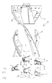
- FIG. 2 shows a partial view of a arranged in the longitudinal direction in the combine separator motor 19 of the axial separator 2 according to Fig. 1 ,
- the separator rotor 19 is provided on its lateral surface 29 in the circumferential direction with strips 28 and Erntegut adaptations instituten 34 in the form of arranged on mounting elements 30 paddles 35.
- the paddles 35 are detachably arranged on the mounting elements 30, which are designed as profile components and are arranged perpendicularly to the lateral surface 29 of the separating motor 19, in order to be able to exchange these as required.
- the running as U-shaped mounting members 30 are connected to the lateral surface 29 of the separator motor 19 by a welded joint, as in Fig. 3 is shown in detail.
- the U-shaped mounting member 30 has two side walls 31 facing one another and a front wall 32 connecting the two side walls 31 at the front side.
- the orientation of the mounting elements 30 is selected in relation to the direction of rotation DR of the separator motor 19 such that the crop treatment element 34 carrying front wall 32 of the mounting member 30 has substantially in the direction of rotation DR of the separator rotor 19.
- the side walls 31 of the mounting member 30 are provided with recesses 33, which in an occurring impact load of the paddle 35 in an order exceeding a threshold value for the impingement of a foreign body, such as a stone or the like, and to a tearing of the mounting member 30 of could cause the lateral surface 29 of the separator motor 19, a yielding of the mounting member 30 allow.
- the mounting member 30 kinks a respectively tilts it against the direction of rotation DR in the direction of the lateral surface 29, so that the tearing off of the mounting member 30 can be avoided by the lateral surface 29 of the Abscheiderotors 19 by the impact load.
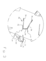
- FIG. 3 is a detailed view of a arranged on the Abscheiderotor 19 mounting member 30 according to Fig. 2 shown. That by welding with the Mantle surface 29 connected mounting member 30 has on its side walls 31 each have a longitudinal weld 36 which extends at least partially along the opposite outer sides of the side walls 31 in the base region of the mounting member 30 in order to connect this with the lateral surface 29 of the Abscheiderotors 19.
- the respective longitudinal weld 36 on the outer side of the respective side wall 31 has in its extension to a weld section 37, which is over the side wall 31, preferably in the direction of rotation DR of the separator rotor 19, out.
- the over the extension of the side walls 31 projecting weld section 37 of the respective longitudinal weld 36 is executed at an angle to the respective side wall 31.
- the distance of the weld seam sections 37 from each other widens in the direction of rotation DR.
- a V-shaped expression has proven to be particularly advantageous.
Landscapes
- Life Sciences & Earth Sciences (AREA)
- Environmental Sciences (AREA)
- Threshing Machine Elements (AREA)
- Harvester Elements (AREA)
- Apparatuses For Bulk Treatment Of Fruits And Vegetables And Apparatuses For Preparing Feeds (AREA)
Abstract
Description
- Die vorliegende Erfindung betrifft ein Montagebauteil zur Befestigung eines Erntegutbehandlungselementes an einem Abscheiderotor, wobei das Montagebauteil als ein Profilbauteil mit sich abschnittsweise in Umfangsrichtung des Abscheiderotors erstreckenden, einander zugewandten Seitenwänden ausgeführt ist.
- Aus der Patentschrift
US 5,192,245 ist ein Montagebauteil zur Befestigung eines Dreschelementes an einem axialen Dresch-Trennrotor bekannt. Das Montagebauteil, an dem das Dreschelement lösbar angeordnet ist, ist als ein Profilbauteil mit sich abschnittsweise in Umfangsrichtung des Abscheiderotors erstreckenden, zueinander parallelen Seitenwänden ausgeführt. Die Seitenwände des Montagebauteiles weisen flügelartige, zu der Mantelfläche des Dresch-Trennrotors parallele Abschnitte auf, mit denen das Montagbauteil mit dem Dresch-Trennrotor durch Punktschweißen verbunden ist. Auf das Montagebauteil ist das L-förmige Dreschelement aufgebracht, welches dem zu bearbeitenden Erntegutstrom unmittelbar ausgesetzt ist. - Als nachteilig an dem Montagebauteil gemäß der
US 5,192,245 erweist sich, dass mit zunehmender radialer Ausdehnung des Montagebauteiles und/oder des daran angeordneten Dreschelementes zu der Mantelfläche des Abscheiderotors die auf dieses einwirkenden Kräfte auf Grund des ungünstiger werdenden Hebelverhältnisses größer werden, so dass ein sicherer Halt des mit der der Mantelfläche des Abscheiderotors verschweißten Montagebauteiles nicht gewährleistet werden kann. Das Ablösen des Montagebauteiles von der Mantelfläche führt zu starken Beschädigungen des Abscheiderotors, die dessen Leistungsfähigkeit negativ beeinflussen. - Aufgabe der vorliegenden Erfindung ist es daher, ein Montagebauteil der eingangs genannten Art derart weiterzuentwickeln, dass eine höhere Standzeit des Abscheiderotors sowie eine höhere Belastbarkeit der Montagebauteile und des daran angeordneten Erntegutbehandlungselementes erreicht wird.
- Die Aufgabe wird erfindungsgemäß durch die kennzeichnenden Merkmale des Patentanspruchs 1 gelöst.
- Vorteilhafte Weiterentwicklungen und Ausgestaltungen der Erfindung sind Gegenstand der jeweiligen Unteransprüche.
- Gemäß dem Anspruch 1 wird vorgeschlagen, dass zur Befestigung des Trägerelementes auf der Oberfläche des Abscheiderotors jede der Seitenwände des Trägerelementes eine im Wesentlichen parallel zu dieser verlaufende Längsschweißnaht mit einem über die Länge der jeweiligen Seitenwand hinausgehenden Schweißnahtabschnitt aufweist. Die Verlängerung der Längsschweißnaht über die Länge der Seitenwand hinaus und die von der fluchtenden Fortführung des Schweißnahtabschnittes abweichende Ausführung führt zu einem Abbau der während des Betriebes des Abscheidrotors auftretenden Spannungsspitzen in den Längsschweißnähten an den Seitenwänden des Montageelementes über die die Seitenwände überragenden Schweißnahtabschnitte.
- Dabei kann der über die Länge der jeweiligen Seitenwand hinausgehende Schweißnahtabschnitt unter einem Winkel zu der jeweiligen Seitenwand ausgeführt sein.
- Vorzugsweise sollte sich der über die Länge der jeweiligen Seitenwand hinausgehende Schweißnahtabschnitt der Längsschweißnaht in Drehrichtung des Abscheiderotors erstrecken. Das von dem Montageelement während des Betriebes des Abscheiderotors aufzunehmende Moment, welches über das mit dem Erntegutbehandlungselement in Berührung kommende Erntegut auf das Montageelement aufgebracht wird, wird in die in die Kraftbeaufschlagungsrichtung verlängerten Schweißnahtabschnitte eingeleitet, wodurch die Spannungsspitzen im Sockelbereich des Montageelementes, dem Übergangsbereich von dem Montageelement zu der Mantelfläche des Abscheiderotors, reduziert werden.
- In vorteilhafter Weiterbildung kann sich der axiale Abstand der Schweißnahtabschnitte der Längsschweißnähte zueinander in Drehrichtung des Abscheiderotors vergrößern, wodurch der Abbau der Spannungsspitzen begünstigt wird.
- Insbesondere kann das Montagebauteil als ein U-Profil ausgeführt sein.
- Vorteilhafterweise können die Seitenwände des Montagebauteiles auf ihrer der Oberfläche des Abscheiderotors zugewandten Seite an die zylindrische Kontur des Abscheiderotors angepasst sein.
- Weiterhin können die Seitenwände eine Aussparung aufweisen. Die Aussparung in den Seitenwänden kann dazu dienen, bei einer auftretenden stoßartigen Belastung des Erntegutbehandlungselementes das Nachgeben des Montageelementes in Drehrichtung des Abscheiderotors zu erreichen, um ein Abreißen des Montageelementes von der Mantelfläche des Abscheiderotors zu vermeiden, was zu einem unbrauchbar werden des Abscheiderotors führen kann. Das eingeknickte Montageelement ist hingegen in vergleichsweise einfacher Weise austauschbar.
- Die Erfindung wird nachstehend anhand eines in den Zeichnungen dargestellten Ausführungsbeispieles näher erläutert.
- Es zeigen:
- Fig. 1
- eine schematisierte Längsschnittdarstellung eines Mähdreschers;
- Fig. 2
- eine Teilansicht eines in Längsrichtung in dem Mähdrescher angeordneten Rotors gemäß
Fig. 1 ; - Fig. 3
- eine Detailansicht eines auf dem Rotor angeordneten Montagelementes gemäß
Fig. 2 . - Der in
Fig. 1 schematisch dargestellte Mähdrescher 1 mit einem Axialabscheider 2 besteht im Wesentlichen aus einem Schneidwerk 3, einer Drescheinrichtung 4, einer Reinigungseinrichtung 5, einem Korntank 6, einer Fahrerkabine 7 sowie aus einem dem Axialabscheider 2 nachgeordneten Strohhäcksler 8. - Das vom Schneidwerk 3 abgeschnittene Erntegut 9 gelangt über einen Schrägförderkanal 10 zu einer nach dem Tangentialprinzip arbeitenden Drescheinrichtung 4. Diese besteht aus einer Dreschtrommel 11 und einem zugeordneten Dreschkorb 12. Die am Dreschkorb 12 abgeschiedenen Erntegutbestandteile werden über einen Förderboden 13 zu einer aus einem Gebläse 14 und einem Ober- und Untersieb 15,16 bestehenden Reinigungseinrichtung 5 geleitet. Das den Dreschkorb 12 in tangentialer Richtung verlassende Korn-Kurzstroh-Gemisch wird in den Axialabscheider 2 gefördert. Der Fördervorgang wird durch eine parallel zur Dreschtrommel 11 angeordnete, rotierende Wendetrommel 17 unterstützt.
- Der Axialabscheider 2 ist in Längsrichtung des Mähdreschers 1 angeordnet und besteht im Wesentlichen aus einem feststehenden, in Förderrichtung FR ansteigenden, zylindrischen Gehäuse 18, in dem ein drehbar angetriebener Abscheiderotor 19 gelagert ist. Das Gehäuse 18 weist einen unteren Bereich mit Abscheidrosten 20 und einen geschlossenen oberen Deckbereich 21 mit an der Innenseite angeordneten Leiteinrichtungen zur Unterstützung der Förderbewegung des Erntegutes auf. Der Umfangsbereich des Abscheiderotors 19 ist mit verschiedenartig ausgebildeten Erntegutbehandlungselementen 34 wie Paddeln 35 oder Leisten 29 versehen, die den Abscheidevorgang intensivieren.
- An den Abscheiderosten 20 werden die im Erntegutgemisch enthaltenen Körner sowie Anteile von Kurzstroh und Spreu abgeschieden und über den darunter liegenden Rücklaufboden 22 zur Reinigungseinrichtung 5 gefördert. Die gereinigten Körner gelangen über eine Förderschnecke 23 und einen Elevator 24 in den Korntank 6. Innerhalb des Axialabscheiders 2 wird das Stroh in Richtung des Abgabebereiches 25 gefördert und gelangt von dort aus über eine Auslassbreite 26 verteilt in den Strohhäcksler 8, der quer zur Fahrtrichtung an einem Rahmen unterhalb der Strohauslaufhaube 27 befestigt ist.
- Die Darstellung in
Fig. 2 zeigt eine Teilansicht eines in Längsrichtung in dem Mähdrescher angeordneten Abscheiderotors 19 des Axialabscheiders 2 gemäßFig. 1 . Der Abscheiderotor 19 ist auf seiner Mantelfläche 29 in Umfangsrichtung mit Leisten 28 sowie Erntegutbehandlungselementen 34 in Form von an Montageelementen 30 angeordneten Paddeln 35 versehen. Die Paddel 35 sind an den als Profilbauteilen ausgeführten, senkrecht zu der Mantelfläche 29 des Abscheiderotors 19 angeordneten Montageelementen 30 lösbar angeordnet, um diese bei Bedarf austauschen zu können. Die als U-Profile ausgeführten Montageelemente 30 sind mit der Mantelfläche 29 des Abscheiderotors 19 durch eine Schweißverbindung verbunden, wie inFig. 3 im Detail dargestellt ist. Das U-förmige Montageelement 30 weist zwei einander zugewandte Seitenwände 31 und eine die beiden Seitenwände 31 stirnseitig miteinander verbindende Vorderwand 32 auf. Die Ausrichtung der Montageelemente 30 ist in Bezug auf die Drehrichtung DR des Abscheiderotors 19 derart gewählt ist, dass die das Erntegutbehandlungselement 34 tragende Vorderwand 32 des Montageelementes 30 im Wesentlichen in die Drehrichtung DR des Abscheiderotors 19 weist. - Die Seitenwände 31 des Montageelementes 30 sind mit Aussparungen 33 versehen, die bei einer auftretenden stoßartigen Belastung des Paddels 35 in einer Größenordnung, die einen Schwellwert für das Auftreffen eines Fremdkörpers, wie einen Stein oder dergleichen, überschreitet, und zu einem Abreißen des Montagelementes 30 von der Mantelfläche 29 des Abscheiderotors 19 führen könnte, ein Nachgeben des Montageelementes 30 ermöglichen. Das Montageelement 30 knickt ein respektive neigt es sich entgegen der Drehrichtung DR in Richtung der Mantelfläche 29, so dass das Abreißen des Montageelementes 30 von der Mantelfläche 29 des Abscheiderotors 19 durch die Stoßbelastung vermieden werden kann.
- In
Fig. 3 ist eine Detailansicht eines auf dem Abscheiderotor 19 angeordneten Montagelementes 30 gemäßFig. 2 dargestellt. Das durch Schweißen mit der Mantelfläche 29 verbundene Montageelement 30 weist an seinen Seitenwänden 31 jeweils eine Längsschweißnaht 36 auf, die sich zumindest abschnittsweise entlang der einander abgewandten Außenseiten der Seitenwände 31 im Sockelbereich des Montageelementes 30 erstreckt, um dieses mit der Mantelfläche 29 des Abscheiderotors 19 zu verbinden. Die jeweilige Längsschweißnaht 36 an der Außenseite der jeweiligen Seitenwand 31 weist in ihrer Verlängerung einen Schweißnahtabschnitt 37 auf, der über die Seitenwand 31, vorzugsweise in Drehrichtung DR des Abscheiderotors 19, hinaus ausgeführt ist. Der über die Erstreckung der Seitenwände 31 hinausragenden Schweißnahtabschnitt 37 der jeweiligen Längsschweißnaht 36 ist unter einem Winkel zu der jeweiligen Seitenwand 31 ausgeführt. Vorteilhafterweise weitet sich der Abstand der Schweißnahtabschnitte 37 zueinander in Drehrichtung DR auf. Dabei hat sich eine V-förmige Ausprägung als besonders vorteilhaft gezeigt. Der wesentliche Vorteil der Verlängerung der Längsschweißnaht 36 über die Länge der Seitenwand 31 hinaus und die von der fluchtenden Fortführung des Schweißnahtabschnittes 37 in Längsrichtung der Seitenwände 31 abweichende Ausführung führt zu einem Abbau der während des Betriebes des Abscheiderotors 19 auftretenden Spannungsspitzen über die durch die Schweißnahtabschnitte 37 verlängerten Längsschweißnähte 36. -
- 1
- Mähdrescher
- 2
- Axialabscheideorgan
- 3
- Schneidwerk
- 4
- Drescheinrichtung
- 5
- Reinigungseinrichtung
- 6
- Korntank
- 7
- Fahrerkabine
- 8
- Strohhäcksler
- 9
- Erntegut
- 10
- Schrägförderkanal
- 11
- Dreschtrommel
- 12
- Dreschkorb
- 13
- Gebläse
- 14
- Förderboden
- 15
- Obersieb
- 16
- Untersieb
- 17
- Wendetrommel
- 18
- Gehäuse
- 19
- Rotor
- 20
- Abscheidrost
- 21
- Deckbereich
- 22
- Rücklaufboden
- 23
- Förderschnecke
- 24
- Elevator
- 25
- Abgabebereich
- 26
- Auslassbreite
- 27
- Strohauslaufhaube
- 28
- Leiste
- 29
- Mantelfläche
- 30
- Montageelement
- 31
- Seitenwand
- 32
- Vorderwand
- 33
- Aussparung
- 34
- Erntgutbehandlungselement
- 35
- Paddel
- 36
- Längsschweißnaht
- 37
- Schweißnahtabschnitt
- FR
- Fahrtrichtung
- DR
- Drehrichtung
Claims (7)
- Montagebauteil (30) zur Befestigung eines Erntegutbehandlungselementes (34, 35) an einem Abscheiderotor (19), wobei das Montagebauteil (30) als ein Profilbauteil mit sich abschnittsweise in Umfangsrichtung des Abscheiderotors (19) erstreckenden, einander zugewandten Seitenwänden (31) ausgeführt ist,
dadurch gekennzeichnet, dass
zur Befestigung des Montagebauteiles (30) auf der Oberfläche des Abscheiderotors (19) jede der Seitenwände (31) des Montagebauteiles (30) eine im Wesentlichen parallel zu dieser verlaufende Längsschweißnaht (36) mit einem über die Länge der jeweiligen Seitenwand (31) hinausgehenden Schweißnahtabschnitt (37) aufweist. - Montagebauteil (30) nach Anspruch 1, dadurch gekennzeichnet, dass der über die Länge der jeweiligen Seitenwand (31) hinausgehende Schweißnahtabschnitt (37) unter einem Winkel zu der jeweiligen Seitenwand (31) ausgeführt ist.
- Montagebauteil (30) nach einem der Ansprüche 1 oder 2, dadurch gekennzeichnet, dass sich der über die Länge der jeweiligen Seitenwand (31) hinausgehende Schweißnahtabschnitt (37) der Längsschweißnaht (36) in Drehrichtung (DR) des Abscheiderotors (19) erstreckt.
- Montagebauteil (30) nach einem der Ansprüche 1 bis 3, dadurch gekennzeichnet, dass sich der axiale Abstand der Schweißnahtabschnitte (37) der Längsschweißnähte (36) zueinander in Drehrichtung (DR) des Abscheiderotors (19) vergrößert.
- Montagebauteil (30) nach einem der Ansprüche 1 bis 4, dadurch gekennzeichnet, dass das Montagebauteil (30) als ein U-Profil ausgeführt ist.
- Montagebauteil (30) nach einem der Ansprüche 1 bis 5, dadurch gekennzeichnet, dass die Seitenwände (31) des Montagebauteiles (30) auf ihrer der Oberfläche des Abscheiderotors (19) zugewandten Seite an die zylindrische Kontur des Abscheiderotors (19) angepasst sind.
- Montagebauteil (30) nach einem der Ansprüche 1 bis 6, dadurch gekennzeichnet, dass die Seitenwände (31) des Montagebauteiles (30) eine Aussparung (33) aufweisen.
Applications Claiming Priority (1)
| Application Number | Priority Date | Filing Date | Title |
|---|---|---|---|
| DE102010009163A DE102010009163A1 (de) | 2010-02-24 | 2010-02-24 | Montagebauteil zur Befestigung eines Erntegutbehandlungselementes an einem Abscheiderotor |
Publications (3)
| Publication Number | Publication Date |
|---|---|
| EP2359677A2 true EP2359677A2 (de) | 2011-08-24 |
| EP2359677A3 EP2359677A3 (de) | 2012-04-18 |
| EP2359677B1 EP2359677B1 (de) | 2013-06-05 |
Family
ID=43983974
Family Applications (1)
| Application Number | Title | Priority Date | Filing Date |
|---|---|---|---|
| EP10192308.4A Active EP2359677B1 (de) | 2010-02-24 | 2010-11-24 | Montagebauteil zur Befestigung eines Erntegutbehandlungselementes an einem Abscheiderotor |
Country Status (3)
| Country | Link |
|---|---|
| US (1) | US8079899B2 (de) |
| EP (1) | EP2359677B1 (de) |
| DE (1) | DE102010009163A1 (de) |
Cited By (5)
| Publication number | Priority date | Publication date | Assignee | Title |
|---|---|---|---|---|
| WO2012110347A1 (en) * | 2011-02-17 | 2012-08-23 | Laverda Spa | Crop engaging elements for a combine harvester separating rotor |
| EP2850935A1 (de) * | 2013-09-24 | 2015-03-25 | CLAAS Selbstfahrende Erntemaschinen GmbH | Abscheidevorrichtung |
| WO2016134859A1 (en) * | 2015-02-25 | 2016-09-01 | Agco International Gmbh | Crop engaging element for a combine harvester separating rotor |
| EP3818812A1 (de) * | 2019-11-05 | 2021-05-12 | CNH Industrial Belgium N.V. | Landwirtschaftliche erntemaschine mit einem schläger mit stossdämpfenden schaufeln |
| RU2844233C1 (ru) * | 2024-03-04 | 2025-07-28 | Общество с ограниченной ответственностью "Комбайновый завод "Ростсельмаш" | Ротор сепарирующего устройства зерноуборочного комбайна |
Families Citing this family (5)
| Publication number | Priority date | Publication date | Assignee | Title |
|---|---|---|---|---|
| DE102010037523A1 (de) * | 2010-09-14 | 2012-03-15 | Demag Cranes & Components Gmbh | Verbindungsanordnung zweier Schienenabschnitte |
| US9924638B1 (en) | 2011-11-23 | 2018-03-27 | Ronald J. Kile | Helical auger flight assemblies and thresher formed therewith |
| US8979623B1 (en) | 2011-11-23 | 2015-03-17 | Ronald J. Kile | Helical auger flight assemblies and thresher formed therewith |
| US11147213B2 (en) * | 2019-01-03 | 2021-10-19 | Cnh Industrial America Llc | Threshing section of a combine |
| US11382273B2 (en) * | 2019-11-04 | 2022-07-12 | Cnh Industrial America Llc | Threshing components for combine harvester |
Citations (1)
| Publication number | Priority date | Publication date | Assignee | Title |
|---|---|---|---|---|
| US5192245A (en) | 1991-09-09 | 1993-03-09 | Case Corporation | Thresher elements for a combine |
Family Cites Families (32)
| Publication number | Priority date | Publication date | Assignee | Title |
|---|---|---|---|---|
| US1450935A (en) * | 1918-12-12 | 1923-04-10 | Air Reduction | Permanent joint in fabricated form and method of maxing the same |
| US3203428A (en) * | 1963-06-21 | 1965-08-31 | William S Ausherman | Threshing cylinder bar |
| BE788802A (nl) * | 1971-07-06 | 1973-01-02 | Clayson Nv | Verbeteringen aan maaidorsers. |
| US4136704A (en) * | 1976-02-19 | 1979-01-30 | Sperry Rand Corporation | Rotor for a combine |
| US4422463A (en) * | 1978-03-24 | 1983-12-27 | Deere & Company | Rotor for an axial flow rotary separator |
| US4192322A (en) * | 1978-05-01 | 1980-03-11 | Deere & Company | Axial flow separator with stepped threshing bar rotor |
| US4248248A (en) * | 1979-04-06 | 1981-02-03 | Sperry Rand Corporation | Interrupted infeed flight means for combine rotor |
| US4280541A (en) * | 1980-01-10 | 1981-07-28 | Reimler Associates, Inc. | Debarking tool for log debarking machines |
| US4505279A (en) * | 1983-08-08 | 1985-03-19 | Sperry Corporation | Staggered spiral rasp bar segments for axial flow combines |
| GB8810759D0 (en) * | 1988-05-06 | 1988-06-08 | Ford New Holland Nv | Axial flow harvesting machine |
| GB8810760D0 (en) * | 1988-05-06 | 1988-06-08 | Ford New Holland Nv | Axial flow harvesting machine |
| US4889517A (en) * | 1989-05-05 | 1989-12-26 | Ford New Holland, Inc. | Overlapping rasp bar rotor for axial flow combines |
| US4936810A (en) * | 1989-05-05 | 1990-06-26 | Ford New Holland, Inc. | Crop thinning elements for axial flow combine |
| US5125871A (en) * | 1991-05-21 | 1992-06-30 | Gorden Marvin J | Axial flow combine rotor having helical extension members in forward threshing area |
| US5192246A (en) * | 1991-11-15 | 1993-03-09 | Case Corporation | Rotor assembly for a combine |
| US5413531A (en) * | 1993-08-06 | 1995-05-09 | Case Corporation | Rotor assembly for a combine |
| US5919086A (en) * | 1997-09-25 | 1999-07-06 | Derry Farms, Inc. | Combine rotor and method |
| CA2254728A1 (en) * | 1998-11-24 | 2000-05-24 | Benoit Guindon | Structures having an insulating concrete component |
| US6190252B1 (en) * | 1998-12-10 | 2001-02-20 | Russell Makeeff | Rotor for a combine-harvester |
| US20020002068A1 (en) * | 1999-01-25 | 2002-01-03 | Welch Terry J. | Enclosed threshing cylinder with rasp-type bars |
| US6325714B1 (en) * | 1999-10-07 | 2001-12-04 | Case Corporation | Rotor assembly for a combine |
| GB2356546A (en) * | 1999-11-26 | 2001-05-30 | Ford New Holland Nv | Threshing and separating unit for axial flow combines |
| US6375564B1 (en) * | 1999-11-29 | 2002-04-23 | Deere & Company | Ramp segment for a combine rotor |
| US6749002B2 (en) * | 2002-10-21 | 2004-06-15 | Ford Motor Company | Method of spray joining articles |
| US7166026B2 (en) * | 2004-07-22 | 2007-01-23 | Cnh America Llc | Stepped grate for an agricultural combine |
| US7022013B1 (en) * | 2004-11-17 | 2006-04-04 | Cnh America Llc | Axial flow combine harvester with adaptable separating unit |
| US20070026913A1 (en) * | 2005-07-27 | 2007-02-01 | Kuchar George J | Crop processing element for a rotary combine |
| US20070049366A1 (en) * | 2005-08-26 | 2007-03-01 | Pope Glenn E | Threshing tine for a combine rotor |
| US7632182B2 (en) * | 2007-01-05 | 2009-12-15 | Cnh America Llc | Locking system for attaching a threshing and/or separating element to a rotor of a threshing system |
| US7632180B2 (en) * | 2007-02-28 | 2009-12-15 | Cnh America Llc | Method of making a rotor for a threshing system of an agricultural combine |
| US7390252B1 (en) * | 2007-02-28 | 2008-06-24 | Cnh America Llc | Agricultural combine rotor with a four inlet impeller arrangement feeding a three rasp bar threshing element layout |
| DE102007030866A1 (de) * | 2007-07-03 | 2009-01-08 | Deere & Company, Moline | Erntegutbearbeitungseinheit mit durchsatzabhängiger Umlaufzahl |
-
2010
- 2010-02-24 DE DE102010009163A patent/DE102010009163A1/de not_active Withdrawn
- 2010-11-24 EP EP10192308.4A patent/EP2359677B1/de active Active
-
2011
- 2011-02-21 US US13/031,450 patent/US8079899B2/en active Active
Patent Citations (1)
| Publication number | Priority date | Publication date | Assignee | Title |
|---|---|---|---|---|
| US5192245A (en) | 1991-09-09 | 1993-03-09 | Case Corporation | Thresher elements for a combine |
Cited By (8)
| Publication number | Priority date | Publication date | Assignee | Title |
|---|---|---|---|---|
| WO2012110347A1 (en) * | 2011-02-17 | 2012-08-23 | Laverda Spa | Crop engaging elements for a combine harvester separating rotor |
| US9198358B2 (en) | 2011-02-17 | 2015-12-01 | Laverda Spa | Crop engaging elements for a combine harvester separating rotor |
| EP2850935A1 (de) * | 2013-09-24 | 2015-03-25 | CLAAS Selbstfahrende Erntemaschinen GmbH | Abscheidevorrichtung |
| WO2016134859A1 (en) * | 2015-02-25 | 2016-09-01 | Agco International Gmbh | Crop engaging element for a combine harvester separating rotor |
| US10342177B2 (en) | 2015-02-25 | 2019-07-09 | Agco International Gmbh | Crop engaging element for a combine harvester separating rotor |
| EP3818812A1 (de) * | 2019-11-05 | 2021-05-12 | CNH Industrial Belgium N.V. | Landwirtschaftliche erntemaschine mit einem schläger mit stossdämpfenden schaufeln |
| WO2021089733A1 (en) * | 2019-11-05 | 2021-05-14 | Cnh Industrial Belgium Nv | Agricultural harvester including a beater with shock absorbent blades |
| RU2844233C1 (ru) * | 2024-03-04 | 2025-07-28 | Общество с ограниченной ответственностью "Комбайновый завод "Ростсельмаш" | Ротор сепарирующего устройства зерноуборочного комбайна |
Also Published As
| Publication number | Publication date |
|---|---|
| EP2359677B1 (de) | 2013-06-05 |
| US20110207511A1 (en) | 2011-08-25 |
| US8079899B2 (en) | 2011-12-20 |
| EP2359677A3 (de) | 2012-04-18 |
| DE102010009163A1 (de) | 2011-08-25 |
Similar Documents
| Publication | Publication Date | Title |
|---|---|---|
| EP2359677B1 (de) | Montagebauteil zur Befestigung eines Erntegutbehandlungselementes an einem Abscheiderotor | |
| DE60015735T2 (de) | Axialflussmähdrescher | |
| EP0958733B1 (de) | Rotor einer Axialtrennvorrichtung | |
| DE69613379T2 (de) | Axialflussmähdrescher | |
| DE2462568C2 (de) | Mähdrescher | |
| DE60201993T2 (de) | Abschirmmittel für einen elevator einer landwirtschaftlichen erntemaschine | |
| DE2132211A1 (de) | Maehdrescher in Axialflussbauart mit rotierender Strohabgabe | |
| DE2729012C2 (de) | Mähdrescher der Axialflußbauart | |
| DE2000605B2 (de) | 24.11.69 V.St.vAmerika 879214 Mähdrescher in Axialflußbauart Sperry Rand Corp, New Holland, Pa. (V.StA.) | |
| DE2233019A1 (de) | Maehdrescher der axialflussbauart | |
| EP2014149B1 (de) | Abscheidetrommel für ein Mehrtrommeldreschwerk | |
| DE2943840A1 (de) | Maehdrescher | |
| EP2850935A1 (de) | Abscheidevorrichtung | |
| EP1733610B1 (de) | Radialgebläse für eine Reinigungseinrichtung für einen Mähdrescher | |
| EP2071935A1 (de) | Mähdrescher mit Reinigungsgebläse | |
| EP1806047B1 (de) | Rotor einer Gutbearbeitungseinrichtung eines Mähdreschers | |
| DE2943838A1 (de) | Maehdrescher | |
| EP1214873A1 (de) | Einlauf einer Axialdreschmaschine | |
| DE102016117598A1 (de) | Abscheidekorb für einen Mähdrescher | |
| EP1378161B1 (de) | Wind-Siebeinrichtung | |
| DE2143532A1 (de) | Dreschgut-Zuführungsvorrichtung bei einem Mähdrescher der Axial-Tangentialflußbauart mit nebeneinander liegenden Arbeitsgehäusen | |
| EP1961289B1 (de) | Landwirtschaftliche Arbeitsmaschine | |
| EP1698222B1 (de) | Mähdrescher | |
| DE602004003542T2 (de) | Axialdreschmähdrescher mit adaptierbarer Trennvorrichtung | |
| DE3209334A1 (de) | Anbaugeraet fuer erntemaschinen zum einzug von erntegut |
Legal Events
| Date | Code | Title | Description |
|---|---|---|---|
| PUAI | Public reference made under article 153(3) epc to a published international application that has entered the european phase |
Free format text: ORIGINAL CODE: 0009012 |
|
| AK | Designated contracting states |
Kind code of ref document: A2 Designated state(s): AL AT BE BG CH CY CZ DE DK EE ES FI FR GB GR HR HU IE IS IT LI LT LU LV MC MK MT NL NO PL PT RO RS SE SI SK SM TR |
|
| AX | Request for extension of the european patent |
Extension state: BA ME |
|
| PUAL | Search report despatched |
Free format text: ORIGINAL CODE: 0009013 |
|
| AK | Designated contracting states |
Kind code of ref document: A3 Designated state(s): AL AT BE BG CH CY CZ DE DK EE ES FI FR GB GR HR HU IE IS IT LI LT LU LV MC MK MT NL NO PL PT RO RS SE SI SK SM TR |
|
| AX | Request for extension of the european patent |
Extension state: BA ME |
|
| RIC1 | Information provided on ipc code assigned before grant |
Ipc: A01F 12/22 20060101ALI20120313BHEP Ipc: A01F 7/06 20060101AFI20120313BHEP |
|
| 17P | Request for examination filed |
Effective date: 20121018 |
|
| GRAP | Despatch of communication of intention to grant a patent |
Free format text: ORIGINAL CODE: EPIDOSNIGR1 |
|
| RIC1 | Information provided on ipc code assigned before grant |
Ipc: A01F 12/22 20060101ALI20130128BHEP Ipc: A01F 7/06 20060101AFI20130128BHEP |
|
| GRAS | Grant fee paid |
Free format text: ORIGINAL CODE: EPIDOSNIGR3 |
|
| GRAA | (expected) grant |
Free format text: ORIGINAL CODE: 0009210 |
|
| AK | Designated contracting states |
Kind code of ref document: B1 Designated state(s): AL AT BE BG CH CY CZ DE DK EE ES FI FR GB GR HR HU IE IS IT LI LT LU LV MC MK MT NL NO PL PT RO RS SE SI SK SM TR |
|
| REG | Reference to a national code |
Ref country code: GB Ref legal event code: FG4D Free format text: NOT ENGLISH |
|
| REG | Reference to a national code |
Ref country code: CH Ref legal event code: EP |
|
| REG | Reference to a national code |
Ref country code: AT Ref legal event code: REF Ref document number: 615083 Country of ref document: AT Kind code of ref document: T Effective date: 20130615 |
|
| REG | Reference to a national code |
Ref country code: IE Ref legal event code: FG4D Free format text: LANGUAGE OF EP DOCUMENT: GERMAN |
|
| REG | Reference to a national code |
Ref country code: DE Ref legal event code: R096 Ref document number: 502010003548 Country of ref document: DE Effective date: 20130801 |
|
| PG25 | Lapsed in a contracting state [announced via postgrant information from national office to epo] |
Ref country code: LT Free format text: LAPSE BECAUSE OF FAILURE TO SUBMIT A TRANSLATION OF THE DESCRIPTION OR TO PAY THE FEE WITHIN THE PRESCRIBED TIME-LIMIT Effective date: 20130605 Ref country code: NO Free format text: LAPSE BECAUSE OF FAILURE TO SUBMIT A TRANSLATION OF THE DESCRIPTION OR TO PAY THE FEE WITHIN THE PRESCRIBED TIME-LIMIT Effective date: 20130905 Ref country code: SI Free format text: LAPSE BECAUSE OF FAILURE TO SUBMIT A TRANSLATION OF THE DESCRIPTION OR TO PAY THE FEE WITHIN THE PRESCRIBED TIME-LIMIT Effective date: 20130605 Ref country code: GR Free format text: LAPSE BECAUSE OF FAILURE TO SUBMIT A TRANSLATION OF THE DESCRIPTION OR TO PAY THE FEE WITHIN THE PRESCRIBED TIME-LIMIT Effective date: 20130906 Ref country code: FI Free format text: LAPSE BECAUSE OF FAILURE TO SUBMIT A TRANSLATION OF THE DESCRIPTION OR TO PAY THE FEE WITHIN THE PRESCRIBED TIME-LIMIT Effective date: 20130605 Ref country code: SE Free format text: LAPSE BECAUSE OF FAILURE TO SUBMIT A TRANSLATION OF THE DESCRIPTION OR TO PAY THE FEE WITHIN THE PRESCRIBED TIME-LIMIT Effective date: 20130605 Ref country code: ES Free format text: LAPSE BECAUSE OF FAILURE TO SUBMIT A TRANSLATION OF THE DESCRIPTION OR TO PAY THE FEE WITHIN THE PRESCRIBED TIME-LIMIT Effective date: 20130916 |
|
| REG | Reference to a national code |
Ref country code: NL Ref legal event code: VDEP Effective date: 20130605 |
|
| REG | Reference to a national code |
Ref country code: LT Ref legal event code: MG4D |
|
| PG25 | Lapsed in a contracting state [announced via postgrant information from national office to epo] |
Ref country code: BG Free format text: LAPSE BECAUSE OF FAILURE TO SUBMIT A TRANSLATION OF THE DESCRIPTION OR TO PAY THE FEE WITHIN THE PRESCRIBED TIME-LIMIT Effective date: 20130905 Ref country code: HR Free format text: LAPSE BECAUSE OF FAILURE TO SUBMIT A TRANSLATION OF THE DESCRIPTION OR TO PAY THE FEE WITHIN THE PRESCRIBED TIME-LIMIT Effective date: 20130605 Ref country code: RS Free format text: LAPSE BECAUSE OF FAILURE TO SUBMIT A TRANSLATION OF THE DESCRIPTION OR TO PAY THE FEE WITHIN THE PRESCRIBED TIME-LIMIT Effective date: 20130605 |
|
| PG25 | Lapsed in a contracting state [announced via postgrant information from national office to epo] |
Ref country code: LV Free format text: LAPSE BECAUSE OF FAILURE TO SUBMIT A TRANSLATION OF THE DESCRIPTION OR TO PAY THE FEE WITHIN THE PRESCRIBED TIME-LIMIT Effective date: 20130605 |
|
| PG25 | Lapsed in a contracting state [announced via postgrant information from national office to epo] |
Ref country code: EE Free format text: LAPSE BECAUSE OF FAILURE TO SUBMIT A TRANSLATION OF THE DESCRIPTION OR TO PAY THE FEE WITHIN THE PRESCRIBED TIME-LIMIT Effective date: 20130605 Ref country code: CZ Free format text: LAPSE BECAUSE OF FAILURE TO SUBMIT A TRANSLATION OF THE DESCRIPTION OR TO PAY THE FEE WITHIN THE PRESCRIBED TIME-LIMIT Effective date: 20130605 Ref country code: SK Free format text: LAPSE BECAUSE OF FAILURE TO SUBMIT A TRANSLATION OF THE DESCRIPTION OR TO PAY THE FEE WITHIN THE PRESCRIBED TIME-LIMIT Effective date: 20130605 Ref country code: IS Free format text: LAPSE BECAUSE OF FAILURE TO SUBMIT A TRANSLATION OF THE DESCRIPTION OR TO PAY THE FEE WITHIN THE PRESCRIBED TIME-LIMIT Effective date: 20131005 Ref country code: PT Free format text: LAPSE BECAUSE OF FAILURE TO SUBMIT A TRANSLATION OF THE DESCRIPTION OR TO PAY THE FEE WITHIN THE PRESCRIBED TIME-LIMIT Effective date: 20131007 |
|
| PG25 | Lapsed in a contracting state [announced via postgrant information from national office to epo] |
Ref country code: NL Free format text: LAPSE BECAUSE OF FAILURE TO SUBMIT A TRANSLATION OF THE DESCRIPTION OR TO PAY THE FEE WITHIN THE PRESCRIBED TIME-LIMIT Effective date: 20130605 Ref country code: PL Free format text: LAPSE BECAUSE OF FAILURE TO SUBMIT A TRANSLATION OF THE DESCRIPTION OR TO PAY THE FEE WITHIN THE PRESCRIBED TIME-LIMIT Effective date: 20130605 Ref country code: RO Free format text: LAPSE BECAUSE OF FAILURE TO SUBMIT A TRANSLATION OF THE DESCRIPTION OR TO PAY THE FEE WITHIN THE PRESCRIBED TIME-LIMIT Effective date: 20130605 |
|
| PLBE | No opposition filed within time limit |
Free format text: ORIGINAL CODE: 0009261 |
|
| STAA | Information on the status of an ep patent application or granted ep patent |
Free format text: STATUS: NO OPPOSITION FILED WITHIN TIME LIMIT |
|
| PG25 | Lapsed in a contracting state [announced via postgrant information from national office to epo] |
Ref country code: DK Free format text: LAPSE BECAUSE OF FAILURE TO SUBMIT A TRANSLATION OF THE DESCRIPTION OR TO PAY THE FEE WITHIN THE PRESCRIBED TIME-LIMIT Effective date: 20130605 |
|
| 26N | No opposition filed |
Effective date: 20140306 |
|
| REG | Reference to a national code |
Ref country code: DE Ref legal event code: R097 Ref document number: 502010003548 Country of ref document: DE Effective date: 20140306 |
|
| PG25 | Lapsed in a contracting state [announced via postgrant information from national office to epo] |
Ref country code: MC Free format text: LAPSE BECAUSE OF FAILURE TO SUBMIT A TRANSLATION OF THE DESCRIPTION OR TO PAY THE FEE WITHIN THE PRESCRIBED TIME-LIMIT Effective date: 20130605 |
|
| REG | Reference to a national code |
Ref country code: FR Ref legal event code: ST Effective date: 20140731 |
|
| REG | Reference to a national code |
Ref country code: IE Ref legal event code: MM4A |
|
| PG25 | Lapsed in a contracting state [announced via postgrant information from national office to epo] |
Ref country code: IE Free format text: LAPSE BECAUSE OF NON-PAYMENT OF DUE FEES Effective date: 20131124 |
|
| PG25 | Lapsed in a contracting state [announced via postgrant information from national office to epo] |
Ref country code: FR Free format text: LAPSE BECAUSE OF NON-PAYMENT OF DUE FEES Effective date: 20131202 |
|
| PG25 | Lapsed in a contracting state [announced via postgrant information from national office to epo] |
Ref country code: SM Free format text: LAPSE BECAUSE OF FAILURE TO SUBMIT A TRANSLATION OF THE DESCRIPTION OR TO PAY THE FEE WITHIN THE PRESCRIBED TIME-LIMIT Effective date: 20130605 |
|
| PG25 | Lapsed in a contracting state [announced via postgrant information from national office to epo] |
Ref country code: TR Free format text: LAPSE BECAUSE OF FAILURE TO SUBMIT A TRANSLATION OF THE DESCRIPTION OR TO PAY THE FEE WITHIN THE PRESCRIBED TIME-LIMIT Effective date: 20130605 Ref country code: CY Free format text: LAPSE BECAUSE OF FAILURE TO SUBMIT A TRANSLATION OF THE DESCRIPTION OR TO PAY THE FEE WITHIN THE PRESCRIBED TIME-LIMIT Effective date: 20130605 |
|
| REG | Reference to a national code |
Ref country code: CH Ref legal event code: PL |
|
| GBPC | Gb: european patent ceased through non-payment of renewal fee |
Effective date: 20141124 |
|
| PG25 | Lapsed in a contracting state [announced via postgrant information from national office to epo] |
Ref country code: LU Free format text: LAPSE BECAUSE OF NON-PAYMENT OF DUE FEES Effective date: 20131124 Ref country code: LI Free format text: LAPSE BECAUSE OF NON-PAYMENT OF DUE FEES Effective date: 20141130 Ref country code: HU Free format text: LAPSE BECAUSE OF FAILURE TO SUBMIT A TRANSLATION OF THE DESCRIPTION OR TO PAY THE FEE WITHIN THE PRESCRIBED TIME-LIMIT; INVALID AB INITIO Effective date: 20101124 Ref country code: MK Free format text: LAPSE BECAUSE OF FAILURE TO SUBMIT A TRANSLATION OF THE DESCRIPTION OR TO PAY THE FEE WITHIN THE PRESCRIBED TIME-LIMIT Effective date: 20130605 Ref country code: CH Free format text: LAPSE BECAUSE OF NON-PAYMENT OF DUE FEES Effective date: 20141130 |
|
| PG25 | Lapsed in a contracting state [announced via postgrant information from national office to epo] |
Ref country code: MT Free format text: LAPSE BECAUSE OF FAILURE TO SUBMIT A TRANSLATION OF THE DESCRIPTION OR TO PAY THE FEE WITHIN THE PRESCRIBED TIME-LIMIT Effective date: 20130605 |
|
| PG25 | Lapsed in a contracting state [announced via postgrant information from national office to epo] |
Ref country code: GB Free format text: LAPSE BECAUSE OF NON-PAYMENT OF DUE FEES Effective date: 20141124 |
|
| REG | Reference to a national code |
Ref country code: AT Ref legal event code: MM01 Ref document number: 615083 Country of ref document: AT Kind code of ref document: T Effective date: 20151124 |
|
| PG25 | Lapsed in a contracting state [announced via postgrant information from national office to epo] |
Ref country code: AT Free format text: LAPSE BECAUSE OF NON-PAYMENT OF DUE FEES Effective date: 20151124 |
|
| PG25 | Lapsed in a contracting state [announced via postgrant information from national office to epo] |
Ref country code: AL Free format text: LAPSE BECAUSE OF FAILURE TO SUBMIT A TRANSLATION OF THE DESCRIPTION OR TO PAY THE FEE WITHIN THE PRESCRIBED TIME-LIMIT Effective date: 20130605 |
|
| P01 | Opt-out of the competence of the unified patent court (upc) registered |
Effective date: 20230515 |
|
| PGFP | Annual fee paid to national office [announced via postgrant information from national office to epo] |
Ref country code: DE Payment date: 20251119 Year of fee payment: 16 |
|
| PGFP | Annual fee paid to national office [announced via postgrant information from national office to epo] |
Ref country code: IT Payment date: 20251125 Year of fee payment: 16 |
|
| PGFP | Annual fee paid to national office [announced via postgrant information from national office to epo] |
Ref country code: BE Payment date: 20251119 Year of fee payment: 16 |