EP2354635B1 - LED-Fassadenstrahler - Google Patents
LED-Fassadenstrahler Download PDFInfo
- Publication number
- EP2354635B1 EP2354635B1 EP11151402.2A EP11151402A EP2354635B1 EP 2354635 B1 EP2354635 B1 EP 2354635B1 EP 11151402 A EP11151402 A EP 11151402A EP 2354635 B1 EP2354635 B1 EP 2354635B1
- Authority
- EP
- European Patent Office
- Prior art keywords
- led
- leds
- facade
- angle
- reference base
- Prior art date
- Legal status (The legal status is an assumption and is not a legal conclusion. Google has not performed a legal analysis and makes no representation as to the accuracy of the status listed.)
- Not-in-force
Links
- 239000011521 glass Substances 0.000 claims description 7
- 230000001678 irradiating effect Effects 0.000 claims description 2
- 238000009432 framing Methods 0.000 description 7
- 238000005286 illumination Methods 0.000 description 6
- 239000000969 carrier Substances 0.000 description 3
- 230000004313 glare Effects 0.000 description 3
- 230000003287 optical effect Effects 0.000 description 3
- 230000005855 radiation Effects 0.000 description 2
- 241000047428 Halter Species 0.000 description 1
- BASFCYQUMIYNBI-UHFFFAOYSA-N platinum Chemical compound [Pt] BASFCYQUMIYNBI-UHFFFAOYSA-N 0.000 description 1
Images


Classifications
-
- F—MECHANICAL ENGINEERING; LIGHTING; HEATING; WEAPONS; BLASTING
- F21—LIGHTING
- F21V—FUNCTIONAL FEATURES OR DETAILS OF LIGHTING DEVICES OR SYSTEMS THEREOF; STRUCTURAL COMBINATIONS OF LIGHTING DEVICES WITH OTHER ARTICLES, NOT OTHERWISE PROVIDED FOR
- F21V14/00—Controlling the distribution of the light emitted by adjustment of elements
- F21V14/02—Controlling the distribution of the light emitted by adjustment of elements by movement of light sources
-
- F—MECHANICAL ENGINEERING; LIGHTING; HEATING; WEAPONS; BLASTING
- F21—LIGHTING
- F21S—NON-PORTABLE LIGHTING DEVICES; SYSTEMS THEREOF; VEHICLE LIGHTING DEVICES SPECIALLY ADAPTED FOR VEHICLE EXTERIORS
- F21S8/00—Lighting devices intended for fixed installation
-
- F—MECHANICAL ENGINEERING; LIGHTING; HEATING; WEAPONS; BLASTING
- F21—LIGHTING
- F21W—INDEXING SCHEME ASSOCIATED WITH SUBCLASSES F21K, F21L, F21S and F21V, RELATING TO USES OR APPLICATIONS OF LIGHTING DEVICES OR SYSTEMS
- F21W2131/00—Use or application of lighting devices or systems not provided for in codes F21W2102/00-F21W2121/00
- F21W2131/10—Outdoor lighting
- F21W2131/107—Outdoor lighting of the exterior of buildings
-
- F—MECHANICAL ENGINEERING; LIGHTING; HEATING; WEAPONS; BLASTING
- F21—LIGHTING
- F21Y—INDEXING SCHEME ASSOCIATED WITH SUBCLASSES F21K, F21L, F21S and F21V, RELATING TO THE FORM OR THE KIND OF THE LIGHT SOURCES OR OF THE COLOUR OF THE LIGHT EMITTED
- F21Y2107/00—Light sources with three-dimensionally disposed light-generating elements
- F21Y2107/50—Light sources with three-dimensionally disposed light-generating elements on planar substrates or supports, but arranged in different planes or with differing orientation, e.g. on plate-shaped supports with steps on which light-generating elements are mounted
-
- F—MECHANICAL ENGINEERING; LIGHTING; HEATING; WEAPONS; BLASTING
- F21—LIGHTING
- F21Y—INDEXING SCHEME ASSOCIATED WITH SUBCLASSES F21K, F21L, F21S and F21V, RELATING TO THE FORM OR THE KIND OF THE LIGHT SOURCES OR OF THE COLOUR OF THE LIGHT EMITTED
- F21Y2115/00—Light-generating elements of semiconductor light sources
- F21Y2115/10—Light-emitting diodes [LED]
Definitions
- LED facade spotlights in which the LEDs are arranged in at least one row and are aligned as an LED bar parallel to a facade or in a Breumrahmung (Faschen).
- the LEDs regularly illuminate the façade or the window framing from below.
- the disadvantage is that the LEDs have a specific, cone-shaped radiation or Lichtaustrittswinkelsektor, which allows a uniform irradiation of the facade or the Breumrahmung only in a dense arrangement of LEDs.
- the disadvantage is that the respective outer region outside the first and last LED of the at least one row of LEDs, due to the conical emission or Lichtaustrittswinkelsektor the LED's, unlit, d. H. So essentially remains dark.
- the US 2008/0062689 A1 describes a receiving device for an LED lighting device, in particular for street lighting.
- the receiving device comprises a plurality of panels, on each of which a plurality of LED rows are arranged in parallel.
- the panels can be rotated relative to a support plate in at least two dimensions.
- the LED rows are pivotable at an angle relative to the respective panel on which they are disposed.
- the invention is therefore based on the object, the LED facade spotlights form so that even outside the first and last LED of the at least one row of LEDs lying area is sufficiently lit.
- the invention provides that at least one LED of the row of LEDs is arranged inclined at an angle to a horizontal reference base.
- This inclined against the horizontal reference base LED also radiates parallel to the horizontal reference base of the LED bar or the LED facade spotlights, so that by means of the horizontal light radiation also an illumination of the outside of the LED bar located areas of the facade or the window framing is possible.
- the two end LEDs are arranged inclined.
- the LEDs of the at least one row of LEDs are set from one end of the row to the other end of the row by an angle inclined relative to the horizontal reference base. This ensures that multiple LEDs contribute to the horizontal light emission of at least one row.
- the inclined relative to the horizontal reference base angle of each LED of at least one row of LEDs and the distance of the LED's from the horizontal reference base from one end of the row to the other end of the series are increasingly larger. This avoids that the horizontal light emissions of adjacent LED's shading each other or hinder each other.
- the at least one row of LEDs is subdivided into two groups of LEDs and that the LEDs of each of the two groups are set from the outer LEDs to the inner LEDs by an angle inclined to the horizontal reference base. This embodiment enables a substantially unobstructed horizontal light emission to both ends of the LED strip or the LED facade spotlight.
- the angle inclined relative to the horizontal reference base and the distance of the LED's to the horizontal reference base from LED to LED of each of the two groups from the outer LED to the inner LED are made increasingly larger.
- the horizontal component of the light emission of the inner LED's can be radiated unhindered by the other LED's of each group to the outside to cause the illumination of lying laterally outside the LED bar or the LED facade spotlight areas of the facade or the window framing.
- the emission direction of the LEDs that can be arranged parallel to a facade can be aligned at an angle to the facade or that the emission direction of the LED that can be arranged in a window frame of a facade can be aligned at an angle from the window to the outside.
- each LED is arranged on a circuit board and the board is aligned together with the associated LED at the respective angle to the horizontal reference base. Furthermore, the circuit board of each LED is arranged on a support which can be oriented relative to the horizontal reference base by the respective angle, and each LED is provided with an optical system. The optics of the outer and inner LEDs of each group are slightly frosted and the optics of the middle LED's are designed as a groove look.
- the LEDs are with carrier, board and optics in a housing with a roof-shaped upper cover and formed with strips of grooved glass arranged above the LEDs.
- the housing can be aligned at a distance from the façade by means of a cantilever arm, which can be arranged horizontally on the façade, or can be fastened to the windowsill by means of a holder which can be mounted on the window sill for the window frame irradiating LED.
- the preferred embodiment of the invention provides a LED facade spotlight with a uniform illumination of the facade with a light outlet extending to the horizontal. Accordingly, a uniform illumination of a Breumrahmung (Faschen) is made possible from the windowsill. A glare to the interior is avoided by special angular position of the LED's.
- LED facade spotlight is also used for a LED facade spotlight, which is arranged in a window framing. Both LED facade spotlights are essentially identical, are used only in different applications.
- the emission or light exit sectors 5 of each LED 2 are formed substantially conical and directed vertically upwards on the facade 6.
- the respective outer region 7 outside the first and last LED 2 of the LED strip 1 remains unlit, that is substantially dark.
- the LED facade radiator 11 according to the invention according to the Fig. 2 to 8 are in a box-shaped housing 11 of flat design and two groups 12 and 13 of four LEDs 14 to 17 and 18 to 21 of low power (less than 20 W) are arranged in a horizontal row.
- the total of eight LED's 14 to 21, the structure and arrangement will be described later, are in the xy plane and in the yz plane at different angles ⁇ , ß aligned.
- the outer LEDs 14 and 21 are arranged on the left and right near the lateral boundary walls 22 and 23 of the housing 11.
- the inner LEDs 17 and 18 are arranged near the central central region 24 of the housing 11.
- the housing 11 is according to Fig. 2 and Fig. 5 provided with a roof-shaped cover 25 with above the LED's 14 to 21 formed, provided with the light of the LED's flared grooved glass 26 cutouts.
- In the housing 11 are also two controllable, electronic control gear 27 for supplying each group 12, 13 of LED's 14 to 17 and 18 to 21 arranged.
- the electronic control gear 27 can be dimmed via a potentiometer, not shown, to produce a uniform brightness in several LED facade spotlights 10 on a facade 30 or at different sizes or heights of windows.
- an LED facade spotlight 10 is mounted by means of a mounting bracket designed as a cantilever 28 and with a determined by the length of the cantilever 28 distance to the facade 30 of a building.
- the emission direction 46 of the parallel to the facade 30 arranged LED's 14 to 21 can be aligned by the angle ß against the facade 30.
- Fig. 4 is an LED facade spotlight 10 by means of a trained as a holder 29 mounting bracket on the windowsill 31 (window sill) a window frame 32nd the window 45 a facade 30 arranged.
- the emission direction 46 of the facade frame 32 of the facade 30 can be arranged LED's 14 to 21 can be aligned by the angle ⁇ from the window 45 to the outside.
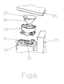
- Each LED 14 to 21 is according to Fig. 6 which shows the right next to the boundary wall 23 arranged LED 21, mounted on a metallic support 33, on which a fixable by means of screws 34 optic holder 35 is placed, which is adapted to receive different optics 36, which serve to direct light and immediately below the groove glass 26 are arranged.
- Each optic 36 additionally includes an upper cover 37 which may be slightly frosted at the outer and inner LEDs 14, 17 and 21, 18 of each group 12 and 13, respectively.
- the upper cover 37 of the middle LED's 15, 16 and 19, 20 of each group 12 or 13 may be formed as a groove optics.
- the LED facade spotlight 10 is preferably equipped for monochrome illumination with white LEDs LED 14 to 21. It is also an RGB-multicolor lighting (red-green-blue) possible. For this purpose, the technical expenses for the operating devices 27 for color control considerably more extensive.
- the eight LEDs 14 to 21 of the two groups 12, 13 are arranged with their carriers 33 at different angles ⁇ 1 to ⁇ 4 relative to the formed from the bottom of the housing 11 horizontal reference base 38, wherein the angle ⁇ 1 to ⁇ 4 of the outer LED 14 and 21 to inner LED 17 and 18 of each group 12 and 13 are formed increasingly larger.
- the regularly vertical light exit direction 39 in the xy plane is increasingly also in the horizontal Light exit direction 40 deflected so that the light exit direction 40 extends in the xy plane in the areas 41 left and right next to the housing 11 of the LED facade radiator 10.
- the optical holders 35 and the optics 36 for directing the light By means of the carriers 33, on which the boards 44 are mounted with the LEDs 14 to 21, the optical holders 35 and the optics 36 for directing the light, the angles ⁇ and ⁇ and the distance 43 of the LEDs 14 to 21 are set to the horizontal reference base 38.
- the Fig. 7 shows the light emission of two LED facade spotlights 10 on a facade 30 in the vertical and also in the horizontal light exit direction 39 and 40, ie in the y- or in the x-direction. It creates a uniform illumination of the facade 30 starting with a horizontal light emission.
- the Fig. 8 shows the example of a Recumrahmung 32, the light emission of an LED facade radiator 10 both in the horizontal x-direction to windowsill 31 without glare to the window 45 out.
- the carrier 33 of the LEDs 14 to 21 are arranged inclined in the yz plane in front of the facade 30 by the angle ß in the z-direction against the facade 30.
- the carriers 33 of the LEDs 14 to 21 in the yz plane of the window framing 32 set by the angle ß in the z-direction to the outside to prevent glare to the interior of the building or towards the window 45 to produce.
Landscapes
- Engineering & Computer Science (AREA)
- General Engineering & Computer Science (AREA)
- Arrangement Of Elements, Cooling, Sealing, Or The Like Of Lighting Devices (AREA)
- Non-Portable Lighting Devices Or Systems Thereof (AREA)
Description
- Die Erfindung bezieht sich auf einen LED-Fassadenstrahler mit mindestens einer Reihe parallel zu einer Fassade oder einer Fensterumrahmung anordenbaren LED's (LED = Light Emitting Diode).
- Es sind LED-Fassadenstrahler vorbekannt, bei denen die LED's in mindestens einer Reihe angeordnet sind und als LED-Leiste parallel zu einer Fassade oder in einer Fensterumrahmung (Faschen) ausgerichtet sind. Die LED's bestrahlen die Fassade bzw. die Fensterumrahmung regelmäßig von unten her. Nachteilig ist, dass die LED's einen bestimmten, kegelförmigen Abstrahlungs- bzw. Lichtaustrittswinkelsektor aufweisen, der nur bei einer dichten Anordnung von LED's eine gleichmässige Bestrahlung der Fassade bzw. der Fensterumrahmung ermöglicht. Nachteilig ist jedoch, dass der jeweils äußere Bereich außerhalb der ersten und letzten LED der mindestens einen Reihe von LED's, bedingt durch den kegelförmigen Abstrahlungs- bzw. Lichtaustrittswinkelsektor der LED's, unbeleuchtet, d. h. also im wesentlichen dunkel bleibt.
- Die
US 2008/0062689 A1 beschreibt eine Aufnahmevorrichtung für eine LED-Beleuchtungseinrichtung, insbesondere zur Straßenbeleuchtung. Die Aufnahmevorrichtung umfasst eine Mehrzahl von Tafel, auf denen jeweils eine Mehrzahl von LED-Reihen parallel angeordnet sind. Die Tafeln können dabei relativ zu einer Trägerplatte in zumindest zwei Dimensionen gedreht werden. Auch die LED-Reihen sind relativ zu der jeweiligen Tafel, auf der sie angeordnet sind, in einem Winkel schwenkbar. - Die
US 2008/0062689 A1 beschreibt eine Aufnahmevorrichtung für eine LED-Beleuchtungseinrichtung, insbesondere zur Straßenbeleuchtung. Die Aufnahmevorrichtung umfasst eine Mehrzahl von Tafel, auf denen jeweils eine Mehrzahl von LED-Reihen parallel angeordnet sind. Die Tafeln können dabei relativ zu einer Trägerplatte in zumindest zwei Dimensionen gedreht werden. Auch die LED-Reihen sind relativ zu der jeweiligen Tafel, auf der sie angeordnet sind, in einem Winkel schwenkbar. - Der Erfindung liegt von daher die Aufgabe zugrunde, den LED-Fassadenstrahler so auszubilden, dass auch der außerhalb der ersten und letzten LED der mindestens einen Reihe von LED's liegende Bereich ausreichend ausgeleuchtet ist.
- Zur Lösung dieser Aufgabe sieht die Erfindung vor, dass mindestens eine LED der Reihe von LED's unter einem Winkel gegen eine horizontale Bezugsbasis geneigt angeordnet ist. Diese gegen die horizontale Bezugsbasis geneigte LED strahlt auch parallel zur horizontalen Bezugsbasis der LED-Leiste bzw. des LED-Fassadenstrahlers, so dass mittels der horizontalen Lichtstrahlung auch eine Ausleuchtung der außerhalb der LED-Leiste gelegenen Bereiche der Fassade bzw. der Fensterumrahmung möglich ist. Zweckmäßigerweise werden hierbei die beiden endseitigen LED's geneigt angeordnet.
- In einer weiteren Ausführungsform der Erfindung ist vorgesehen, dass die LED's der mindestens einen Reihe von LED's von einem Ende der Reihe zum anderen Ende der Reihe um einen gegen die horizontale Bezugsbasis geneigten Winkel angestellt sind. Hierdurch wird erreicht, dass mehrere LED's der mindestens einen Reihe zur horizontalen Lichtausstrahlung mit beitragen.
- In weiterer Ausbildung dieser Ausführungsform ist vorgesehen, dass der gegen die horizontale Bezugsbasis geneigte Winkel jeder LED der mindestens einen Reihe von LED's und der Abstand der LED's von der horizontalen Bezugsbasis von einem Ende der Reihe zum anderen Ende der Reihe zunehmend größer ausgebildet sind. Hierdurch wird vermieden, dass sich die horizontalen Lichtausstrahlungen benachbarter LED's gegenseitig beschatten bzw. behindern. Gemäß der Erfindung ist vorgesehen, dass die mindestens eine Reihe von LED's in zwei Gruppen von LED's unterteilt ist und dass die LED's jeder der beiden Gruppen von den äußeren LED's zu den inneren LED's um einen gegen die horizontale Bezugsbasis geneigten Winkel angestellt sind. Diese Ausführungsform ermöglicht eine im wesentlichen unbehinderte horizontale Lichtausstrahlung zu beiden Enden der LED-Leiste bzw. des LED-Fassadenstrahlers.
- Gemäß der Erfindung ist vorgesehen, dass der gegen die horizontale Bezugsbasis geneigte Winkel und der Abstand der LED's zu der horizontalen Bezugsbasis von LED zu LED jeder der beiden Gruppen von der äußeren LED zur inneren LED zunehmend größer ausgebildet sind. Hierdurch kann die horizontale Komponente der Lichtausstrahlung der inneren LED's unbehindert von den übrigen LED's einer jeden Gruppe zur Außenseite abgestrahlt werden, um die Beleuchtung der seitlich außerhalb der LED-Leiste bzw. des LED-Fassadenstrahlers liegenden Bereiche der Fassade bzw. der Fensterumrahmung zu bewirken.
- In weiterer Ausbildung beider erfindungsgemäßer Ausführungsformen ist vorgesehen, dass die Ausstrahlungsrichtung der parallel zu einer Fassade anordenbaren LED's um einen Winkel gegen die Fassade ausrichtbar ist bzw. dass die Ausstrahlungsrichtung der in einer Fensterumrahmung einer Fassade anordenbaren LED's um einen Winkel vom Fenster nach außen ausrichtbar ist.
- In noch weiterer Ausbildung beider erfindungsgemäßer Ausführungsformen des LED-Fassadenstrahlers ist vorgesehen, dass jede LED auf einer Platine angeordnet ist und die Platine zusammen mit der zugeordneten LED um den jeweiligen Winkel gegen die horizontale Bezugsbasis ausrichtbar ist. Ferner ist die Platine einer jeden LED auf einem gegen die horizontale Bezugsbasis um den jeweiligen Winkel ausrichtbaren Träger angeordnet, und jede LED ist mit einer Optik versehen. Die Optik der äußeren und inneren LED's jeder Gruppe sind leicht mattiert und die Optik der mittleren LED's als Rillenoptik ausgebildet.
- In noch weiterer Ausbildung des erfindungsgemäßen LED-Fassadenstrahlers sind die LED's mit Träger, Platine und Optik in einem Gehäuse mit einer dachförmigen oberen Abdeckung und mit oberhalb der LED's angeordneten Streifen aus Rillenglas ausgebildet. Das Gehäuse ist mittels eines an der Fassade im wesentlichen horizontal anordenbaren Kragarm im Abstand zur Fassade ausrichtbar bzw. für die eine Fensterumrahmung bestrahlenden LED's mittels eines auf der Fensterbank montierbaren Halters auf der Fensterbank befestigbar.
- Die bevorzugte Ausführungsform der Erfindung schafft einen LED-Fassadenstrahler mit einer gleichmäßigen Beleuchtung der Fassade mit einem bis zur Waagerechten verlaufenden Lichtaustritt. Entsprechend wird eine gleichmäßige Beleuchtung einer Fensterumrahmung (Faschen) ab der Fensterbank ermöglicht. Eine Blendung zum Innenraum wird durch besondere Winkelstellung der LED's vermieden.
- Es wird die Bezeichnung LED-Fassadenstrahler auch für einen LED-Fassadenstrahler verwendet, der in einer Fensterumrahmung angeordnet ist. Beide LED-Fassadenstrahler sind im wesentlichen baugleich, werden nur in verschiedenen Anwendungsbereichen eingesetzt.
- Die Erfindung ist nachfolgend anhand der bevorzugten Ausführungsform eines LED-Fassadenstrahlers näher erläutert. Es zeigt:
- Fig. 1
- eine LED-Leiste eines LED-Fassadenstrahlers gemäß dem Stand der Technik,
- Fig. 2
- einen horizontalen Längsschnitt durch den erfindungsgemäßen LED-Fassadenstrahler,
- Fig. 3
- einen horizontalen Querschnitt durch den mittels eines Kragarmes an einer Fassade angeordneten LED-Fassadenstrahler,
- Fig. 4
- einen horizontalen Querschnitt durch den mittels eines Halters auf der Fensterbank einer Fensterumrahmung angeordneten LED-Fassadenstrahler,
- Fig. 5
- eine geschnitten dargestellte Draufsicht auf den gemäß
Fig. 4 auf der Fensterbank angeordneten LED-Fassadenstrahler, - Fig. 6
- eine Explosionsdarstellung der Anordnung einer LED mit Platine, Optik mit Optikhalter und Rillenglasabdeckung,
- Fig. 7
- eine Ansicht auf die Ausstrahlung zweier im Abstand voneinander an einer Fassade angeordneten LED-Fassadenstrahlern und
- Fig. 8
- eine Ansicht auf die Ausstrahlung eines in einer Fensterumrahmung angeordneten LED-Fassadenstrahlers.
- Der in
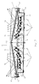
Fig. 1 gezeigte LED-Fassadenstrahler gemäß dem Stand der Technik besteht aus einer rahmenförmigen LED-Leiste 1 mit dreizehn, in horizontaler Reihe ausgerichteten LED's 2 (LED = Light Emitting Diode) mit aufgesetzter Optik 3 und einer oberen Abdeckung 4 aus Rillenglas. Die Abstrahlungs- bzw. Lichtaustrittssektoren 5 einer jeden LED 2 sind im Wesentlichen kegelförmig ausgebildet und vertikal nach oben auf die Fassade 6 gerichtet. Der jeweils äußere Bereich 7 außerhalb der ersten und letzten LED 2 der LED-Leiste 1 bleibt unbeleuchtet, also im wesentlichen dunkel. - In der bevorzugten Ausführungsform des LED-Fassadenstrahlers 11 gemäß der Erfindung nach den
Fig. 2 bis 8 sind in einem kastenförmigen Gehäuse 11 von flacher Bauform und in einer horizontalen Reihe zwei Gruppen 12 und 13 von je vier LED's 14 bis 17 bzw. 18 bis 21 mit geringer Leistung (kleiner als 20 W) angeordnet. Die insgesamt acht LED's 14 bis 21, deren Aufbau und Anordnung später noch beschrieben werden wird, sind in der x-y-Ebene als auch in der y-z-Ebene in verschiedenen Winkeln α, ß ausrichtbar. Die äußeren LED's 14 bzw. 21 sind links und rechts nahe den seitlichen Begrenzungswänden 22 bzw. 23 des Gehäuses 11 angeordnet. Die inneren LED's 17 bzw. 18 sind nahe dem mittleren Zentralbereich 24 des Gehäuses 11 angeordnet. - Das Gehäuse 11 ist gemäß
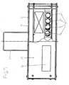
Fig. 2 undFig. 5 mit einer dachförmig ausgebildeten Abdeckung 25 mit oberhalb der LED's 14 bis 21 ausgebildeten, mit das Licht der LED's aufweitendem Rillenglas 26 versehenen Ausschnitten versehen. Im Gehäuse 11 sind ferner zwei steuerbare, elektronische Betriebsgeräte 27 zur Versorgung je einer Gruppe 12, 13 von LED's 14 bis 17 bzw. 18 bis 21 angeordnet. Die elektronischen Betriebsgeräte 27 können über ein nicht dargestelltes Potentiometer gedimmt werden, um bei mehreren LED-Fassadenstrahlern 10 an einer Fassade 30 bzw. bei unterschiedlichen Größen bzw. Höhen von Fenstern eine gleichmäßige Helligkeit zu erzeugen. - Gemäß
Fig. 3 ist ein LED-Fassadenstrahler 10 mittels eines als Kragarm 28 ausgebildeten Montagebügels und mit einem durch die Länge des Kragarmes 28 bestimmten Abstand an der Fassade 30 eines Gebäudes angebracht. Die Ausstrahlungsrichtung 46 der parallel zu der Fassade 30 angeordneten LED's 14 bis 21 ist um den Winkel ß gegen die Fassade 30 ausrichtbar. - Gemäß
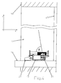
Fig. 4 ist ein LED-Fassadenstrahler 10 mittels eines als Halter 29 ausgebildeten Montagebügels auf der Fensterbank 31 (Fenstersims) einer Fensterumrahmung 32 des Fensters 45 einer Fassade 30 angeordnet. Die Ausstrahlungsrichtung 46 der in der Fassadenumrahmung 32 der Fassade 30 anordenbaren LED's 14 bis 21 ist um den Winkel β vom Fenster 45 nach außen ausrichtbar. - Jede LED 14 bis 21 ist gemäß
Fig. 6 , welche die rechts neben der Begrenzungswand 23 angeordnete LED 21 zeigt, auf einem metallischen Träger 33 gelagert, auf dem ein mittels Schrauben 34 festlegbarer Optikhalter 35 aufgesetzt ist, der zur Aufnahme unterschiedlicher Optiken 36 ausgebildet ist, die zur Lichtlenkung dienen und unmittelbar unterhalb des Rillenglases 26 angeordnet sind. - Jede Optik 36 umfasst zusätzlich eine obere Abdeckung 37, die bei den äußeren und inneren LED's 14, 17 bzw. 21, 18 jeder Gruppe 12 bzw. 13 leicht mattiert sein kann. Die obere Abdeckung 37 der mittleren LED's 15, 16 und 19, 20 jeder Gruppe 12 bzw. 13 kann als Rillenoptik ausgebildet sein.
- Der LED-Fassadenstrahler 10 ist vorzugsweise zur monochromen Beleuchtung mit weiß leuchtenden LED's 14 bis 21 bestückt. Es ist auch eine RGB-Multicolor Beleuchtung (rot-grün-blau) möglich. Hierzu sind die technischen Aufwendungen für die Betriebsgeräte 27 zwecks Farbsteuerung erheblich umfangreicher.
- Wie es die
Fig. 2 zeigt, sind die acht LED's 14 bis 21 der beiden Gruppen 12, 13 mit ihren Trägern 33 in unterschiedlichen Winkeln α1 bis α4 gegenüber der vom Boden des Gehäuses 11 gebildeten horizontalen Bezugsbasis 38 angeordnet, wobei die Winkel α1 bis α4 von der äußeren LED 14 bzw. 21 zu inneren LED 17 bzw. 18 einer jeden Gruppe 12 bzw. 13 zunehmend größer ausgebildet sind. Dadurch wird die regulär vertikale Lichtaustrittsrichtung 39 in der x-y-Ebene zunehmend auch in die waagerechte Lichtaustrittsrichtung 40 umgelenkt, so dass sich die Lichtaustrittsrichtung 40 in der x-y-Ebene auch in die Bereiche 41 links und rechts neben dem Gehäuse 11 des LED-Fassadenstrahlers 10 erstreckt. Durch diese Kombination der LED's 14 bis 21 mit unterschiedlicher Lichtaustrittsrichtung 39, 40 wird ein gleichmäßiger und waagerechter bzw. in x-Richtung auch negativer Lichtaustritt erzeugt. Durch seitlich des Gehäuses 11 anbringbare Blenden 42 kann der Lichtaustritt in der waagerechten Lichtaustrittsrichtung 40 begrenzt werden. - Mittels der Träger 33, auf denen die Platinen 44 mit den LED's 14 bis 21, den Optikhaltern 35 und den Optiken 36 zur Lichtlenkung montiert sind, werden die Winkel α und ß und der Abstand 43 der LED's 14 bis 21 zur horizontalen Bezugsbasis 38 eingestellt.
- Die
Fig 7 zeigt den Lichtaustritt zweier LED-Fassadenstrahler 10 an einer Fassade 30 in der vertikalen und auch in der horizontalen Lichtaustrittsrichtung 39 bzw. 40, d. h. in der y- bzw. in der x-Richtung. Es wird eine gleichmäßige Beleuchtung der Fassade 30 beginnend mit einem waagerechten Lichtaustritt erzeugt. - Die
Fig. 8 zeigt am Beispiel einer Fensterumrahmung 32 den Lichtaustritt eines LED-Fassadenstrahlers 10 sowohl in der horizontalen x-Richtung bis Fensterbank 31 ohne Blendung zum Fenster 45 hin erzeugt. - Wie es in der
Fig. 3 dargestellt ist, sind die Träger 33 der LED's 14 bis 21 in der y-z-Ebene vor der Fassade 30 um den Winkel ß in der z-Richtung gegen die Fassade 30 geneigt angeordnet. - Wie es in der
Fig. 4 dargestellt ist, sind die Träger 33 der LED's 14 bis 21 in der y-z-Ebene der Fensterumrahmung 32 um den Winkel ß in z-Richtung nach außen angestellt, um keine Blendung zum Innenraum des Gebäudes bzw. in Richtung zum Fenster 45 zu erzeugen. -
- 1
- LED-Leiste gemäß dem Stand der Technik
- 2
- LED
- 3
- Optik
- 4
- Abdeckung
- 5
- Abstrahlungs-/Lichtaustrittswinkelsektor
- 6
- Fassade
- 7
- Bereich
- 10
- LED-Fassadenstrahler gemäß der Erfindung
- 11
- Gehäuse
- 12, 13
- Gruppe
- 14
- bis 21 LED
- 22, 23
- Begrenzungswand
- 24
- Zentralbereich
- 25
- Abdeckung
- 26
- Rillenglas
- 27
- Betriebsgerät
- 28
- Kragarm
- 29
- Halter
- 30
- Fassade
- 31
- Fensterbank
- 32
- Fensterumrahmung
- 33
- Träger
- 34
- Schraube
- 35
- Optikhalter
- 36
- Optik
- 37
- obere Abdeckung
- 38
- horizontale Bezugsbasis
- 39
- vertikale Lichtaustrittsrichtung
- 40
- horizontale Lichtaustrittsrichtung
- 41
- Bereich
- 42
- Blende
- 43
- Abstand
- 44
- Platine
- 45
- Fenster
- 46
- Ausstrahlungsrichtung
Claims (10)
- LED-Fassadenstrahler mit mindestens einer Reihe parallel zu einer Fassade oder einer Fensterumrahmung anordenbaren LED's,
wobei
mindestens eine LED (14 bis 21) der Reihe von LED's unter einem Winkel (α) gegen eine horizontale Bezugsbasis (38) geneigt angeordnet ist,
dadurch gekennzeichnet, dass
die mindestens eine Reihe von LED's (17 bis 21) in zwei Gruppen (12, 13) von LED's unterteilt ist und dass die LED's (17 bis 21) jeder der beiden Gruppen (12, 13) von den äußeren LED's(14, 21) zu den inneren LED's (17, 18) um einen gegen die horizontale Bezugsbasis (38) geneigten Winkel (α) angestellt sind, und dass
der gegen die horizontale Bezugsbasis (38) geneigte Winkel (α) und der Abstand (43) der LED's (14 bis 21) zu der horizontalen Bezugsbasis (38) von LED zu LED jeder der beiden Gruppen (12, 13) von der äußeren LED (14, 21) zur inneren LED (17, 18) zunehmend größer ausgebildet sind. - LED-Fassadenstrahler nach Anspruch 1, dadurch gekennzeichnet, dass die Ausstrahlungsrichtung (46) der parallel zu einer Fassade (30) anordenbaren LED's (14 bis 21) um einen Winkel (ß) gegen die Fassade (30) ausrichtbar ist.
- LED-Fassadenstrahler nach einem der Ansprüche 1 bis 2, dadurch gekennzeichnet, dass die Ausstrahlungsrichtung (46) der in einer Fensterumrahmung (32) einer Fassade (30) anordenbaren LED's (14 bis 21) um einen Winkel (ß) vom Fenster (45) nach außen hin ausrichtbar ist.
- LED-Fassadenstrahler nach einem der Ansprüche 1 bis 3, dadurch gekennzeichnet, dass jede LED (14 bis 21) auf einer Platine (44) angeordnet ist und die Platine (44) zusammen mit der zugeordneten LED (14 bis 21) um den jeweiligen Winkel (a, ß) gegen die horizontale Bezugsbasis (38) ausrichtbar ist.
- LED-Fassadenstrahler nach Anspruch 4, dadurch gekennzeichnet, das die Platine (44) einer jeden LED (14 bis 21) auf einem gegen die horizontale Bezugsbasis (38) um den jeweiligen Winkel (α, ß) ausrichtbaren Träger (33) angeordnet ist.
- LED-Fassadenstrahler nach Anspruch 4 oder 5, dadurch gekennzeichnet, dass jede LED (14 bis 21) mit einer Optik (36) zur Lichtlenkung versehen ist.
- LED-Fassadenstrahler nach Anspruch 6, dadurch gekennzeichnet, dass die Optik (36) der äußeren und inneren LED's (14, 21 bzw. 17, 18) jeder Gruppe (12, 13) leicht mattiert und die Optik (36) der mittleren LED's (15, 16 bzw. 19, 20) als Rillenoptik ausgebildet sind
- LED-Fassadenstrahler nach einem der Ansprüche 1 bis 7, dadurch gekennzeichnet, dass die LED's (14 bis 21) mit Träger (33), Platine (44) und Optik (36) in einem Gehäuse (11) mit einer dachförmigen oberen Abdeckung (37) angeordnet sind, die oberhalb der LED's (14 bis 21) mit einem Rillenglas (26) versehen ist.
- LED-Fassadenstrahler nach Anspruch 8, dadurch gekennzeichnet, dass das Gehäuse (11) mittels eines an der Fassade (30) im Wesentlichen horizontal anordenbaren Kragarmes (28) im Abstand zur Fassade (30) ausrichtbar ist.
- LED-Fassadenstrahler nach Anspruch 8, dadurch gekennzeichnet, dass das Gehäuse (11) für die eine Fensterumrahmung (32) bestrahlenden LED's (14 bis 21) mittels eines auf der Fensterbank (31) montierbaren Halters (29) auf der Fensterbank (31) befestigbar ist.
Applications Claiming Priority (1)
| Application Number | Priority Date | Filing Date | Title |
|---|---|---|---|
| DE102010006248A DE102010006248B3 (de) | 2010-01-28 | 2010-01-28 | LED-Fassadenstrahler |
Publications (3)
| Publication Number | Publication Date |
|---|---|
| EP2354635A1 EP2354635A1 (de) | 2011-08-10 |
| EP2354635B1 true EP2354635B1 (de) | 2015-09-30 |
| EP2354635B8 EP2354635B8 (de) | 2015-11-11 |
Family
ID=43587339
Family Applications (1)
| Application Number | Title | Priority Date | Filing Date |
|---|---|---|---|
| EP11151402.2A Not-in-force EP2354635B8 (de) | 2010-01-28 | 2011-01-19 | LED-Fassadenstrahler |
Country Status (2)
| Country | Link |
|---|---|
| EP (1) | EP2354635B8 (de) |
| DE (1) | DE102010006248B3 (de) |
Families Citing this family (2)
| Publication number | Priority date | Publication date | Assignee | Title |
|---|---|---|---|---|
| EP2581644B1 (de) * | 2011-10-10 | 2018-03-21 | Induperm A/S | LED-Anflugfeuer |
| DE102012112644B4 (de) * | 2012-12-19 | 2024-05-16 | Odos Imaging Ltd. | Strahler zum Beleuchten eines Objekts und Abstandsmessvorrichtung mit dem Strahler |
Family Cites Families (11)
| Publication number | Priority date | Publication date | Assignee | Title |
|---|---|---|---|---|
| US5101326A (en) * | 1990-09-27 | 1992-03-31 | The Grote Manufacturing Co. | Lamp assembly for motor vehicle |
| DE29817609U1 (de) * | 1998-09-02 | 2000-01-13 | Derksen, Gabriele, 45889 Gelsenkirchen | Leuchtmittel |
| US7631985B1 (en) * | 2005-05-02 | 2009-12-15 | Genlyte Thomas Group, Llc | Finite element and multi-distribution LED luminaire |
| DE102006018603B3 (de) * | 2006-04-21 | 2007-12-27 | Paul Heinrich Neuhorst | Leuchte |
| US7712926B2 (en) * | 2006-08-17 | 2010-05-11 | Koninklijke Philips Electronics N.V. | Luminaire comprising adjustable light modules |
| US7665862B2 (en) * | 2006-09-12 | 2010-02-23 | Cree, Inc. | LED lighting fixture |
| DE202007001078U1 (de) * | 2007-01-18 | 2008-02-21 | Bocom Energiespar-Technologien Gmbh | Leuchte |
| EP2107296A3 (de) * | 2008-04-05 | 2010-06-16 | Es-System S.A. | System zur Beleuchtung einer Straße und Beleuchtungsvorrichtung für eine Straße |
| DE102008022738A1 (de) * | 2008-05-08 | 2009-11-12 | Christian Bartenbach | Fassadenbeleuchtungsvorrichtung sowie Fassadenstrahler hierfür |
| WO2010026279A1 (en) * | 2008-09-03 | 2010-03-11 | Artequa Oy | Illuminating device |
| DE202008014125U1 (de) * | 2008-10-23 | 2009-04-02 | Semperlux Aktiengesellschaft - Lichttechnische Werke - | Leuchte mit LED-Flächen-Anstrahlung |
-
2010
- 2010-01-28 DE DE102010006248A patent/DE102010006248B3/de not_active Expired - Fee Related
-
2011
- 2011-01-19 EP EP11151402.2A patent/EP2354635B8/de not_active Not-in-force
Also Published As
| Publication number | Publication date |
|---|---|
| EP2354635B8 (de) | 2015-11-11 |
| EP2354635A1 (de) | 2011-08-10 |
| DE102010006248B3 (de) | 2011-07-14 |
Similar Documents
| Publication | Publication Date | Title |
|---|---|---|
| DE69207633T2 (de) | Leuchtanzeigevorrichtung | |
| EP2151899B1 (de) | Lichtbandsystem | |
| EP2071227A1 (de) | Wand- und/oder Deckenleuchte | |
| DE102013110342B4 (de) | Beleuchtungsvorrichtung für Fahrzeuge | |
| EP2610541A1 (de) | Decken-Beleuchtungsanordnung | |
| DE10039095A1 (de) | Anordnung von lichtabstrahlenden plattenförmigen Elementen | |
| EP3042120B1 (de) | Anordnung zur lichtabgabe | |
| EP2354635B1 (de) | LED-Fassadenstrahler | |
| EP2472177B1 (de) | Leuchte | |
| DE202010001465U1 (de) | LED-Fassadenstrahler | |
| DE202014000264U1 (de) | Leuchtvorrichtung | |
| DE202004009194U1 (de) | Modulare LED-Beleuchtungseinrichtung | |
| EP2472178B1 (de) | Einbauleuchte | |
| DE9319537U1 (de) | Beleuchtungsvorrichtung | |
| EP2924349B1 (de) | Vollflächig erleuchtete Leuchte | |
| EP3081855B1 (de) | Scheinwerfer | |
| EP2989378B1 (de) | Led-leuchte mit unterschiedlich einstellbaren lichtverteilungen | |
| DE202005005616U1 (de) | Trennwandelement | |
| DE202007013177U1 (de) | Leuchte | |
| DE102016104221A1 (de) | LED-Leuchte mit Lichtlenkelement | |
| EP1106914A1 (de) | Anordnung von lichtabstrahlenden plattenförmigen Elementen | |
| EP1106915A1 (de) | Anordnung von lichtstrahlenden plattenförmigen Elementen | |
| DE202023002558U1 (de) | Leuchte für Arbeitsfeldbeleuchtung | |
| EP2946662B1 (de) | Beleuchtungseinrichtung für ein aquarium oder terrarium | |
| DE202025105460U1 (de) | Leuchtvorrichtung für die Emission von Umgebungslicht |
Legal Events
| Date | Code | Title | Description |
|---|---|---|---|
| PUAI | Public reference made under article 153(3) epc to a published international application that has entered the european phase |
Free format text: ORIGINAL CODE: 0009012 |
|
| AK | Designated contracting states |
Kind code of ref document: A1 Designated state(s): AL AT BE BG CH CY CZ DE DK EE ES FI FR GB GR HR HU IE IS IT LI LT LU LV MC MK MT NL NO PL PT RO RS SE SI SK SM TR |
|
| AX | Request for extension of the european patent |
Extension state: BA ME |
|
| 17P | Request for examination filed |
Effective date: 20120209 |
|
| 17Q | First examination report despatched |
Effective date: 20140528 |
|
| GRAP | Despatch of communication of intention to grant a patent |
Free format text: ORIGINAL CODE: EPIDOSNIGR1 |
|
| RIC1 | Information provided on ipc code assigned before grant |
Ipc: F21W 131/107 20060101ALN20150116BHEP Ipc: F21S 8/00 20060101AFI20150116BHEP |
|
| INTG | Intention to grant announced |
Effective date: 20150209 |
|
| 19U | Interruption of proceedings before grant |
Effective date: 20131201 |
|
| 19W | Proceedings resumed before grant after interruption of proceedings |
Effective date: 20150803 |
|
| GRAS | Grant fee paid |
Free format text: ORIGINAL CODE: EPIDOSNIGR3 |
|
| GRAA | (expected) grant |
Free format text: ORIGINAL CODE: 0009210 |
|
| AK | Designated contracting states |
Kind code of ref document: B1 Designated state(s): AL AT BE BG CH CY CZ DE DK EE ES FI FR GB GR HR HU IE IS IT LI LT LU LV MC MK MT NL NO PL PT RO RS SE SI SK SM TR |
|
| REG | Reference to a national code |
Ref country code: CH Ref legal event code: EP Ref country code: GB Ref legal event code: FG4D Free format text: NOT ENGLISH |
|
| REG | Reference to a national code |
Ref country code: AT Ref legal event code: REF Ref document number: 752634 Country of ref document: AT Kind code of ref document: T Effective date: 20151015 |
|
| REG | Reference to a national code |
Ref country code: IE Ref legal event code: FG4D Free format text: LANGUAGE OF EP DOCUMENT: GERMAN |
|
| RAP2 | Party data changed (patent owner data changed or rights of a patent transferred) |
Owner name: SILL LEUCHTEN GMBH |
|
| REG | Reference to a national code |
Ref country code: DE Ref legal event code: R096 Ref document number: 502011007956 Country of ref document: DE |
|
| PG25 | Lapsed in a contracting state [announced via postgrant information from national office to epo] |
Ref country code: LV Free format text: LAPSE BECAUSE OF FAILURE TO SUBMIT A TRANSLATION OF THE DESCRIPTION OR TO PAY THE FEE WITHIN THE PRESCRIBED TIME-LIMIT Effective date: 20150930 Ref country code: NO Free format text: LAPSE BECAUSE OF FAILURE TO SUBMIT A TRANSLATION OF THE DESCRIPTION OR TO PAY THE FEE WITHIN THE PRESCRIBED TIME-LIMIT Effective date: 20151230 Ref country code: GR Free format text: LAPSE BECAUSE OF FAILURE TO SUBMIT A TRANSLATION OF THE DESCRIPTION OR TO PAY THE FEE WITHIN THE PRESCRIBED TIME-LIMIT Effective date: 20151231 Ref country code: FI Free format text: LAPSE BECAUSE OF FAILURE TO SUBMIT A TRANSLATION OF THE DESCRIPTION OR TO PAY THE FEE WITHIN THE PRESCRIBED TIME-LIMIT Effective date: 20150930 Ref country code: LT Free format text: LAPSE BECAUSE OF FAILURE TO SUBMIT A TRANSLATION OF THE DESCRIPTION OR TO PAY THE FEE WITHIN THE PRESCRIBED TIME-LIMIT Effective date: 20150930 |
|
| REG | Reference to a national code |
Ref country code: NL Ref legal event code: MP Effective date: 20150930 |
|
| REG | Reference to a national code |
Ref country code: LT Ref legal event code: MG4D |
|
| PG25 | Lapsed in a contracting state [announced via postgrant information from national office to epo] |
Ref country code: RS Free format text: LAPSE BECAUSE OF FAILURE TO SUBMIT A TRANSLATION OF THE DESCRIPTION OR TO PAY THE FEE WITHIN THE PRESCRIBED TIME-LIMIT Effective date: 20150930 Ref country code: HR Free format text: LAPSE BECAUSE OF FAILURE TO SUBMIT A TRANSLATION OF THE DESCRIPTION OR TO PAY THE FEE WITHIN THE PRESCRIBED TIME-LIMIT Effective date: 20150930 Ref country code: SE Free format text: LAPSE BECAUSE OF FAILURE TO SUBMIT A TRANSLATION OF THE DESCRIPTION OR TO PAY THE FEE WITHIN THE PRESCRIBED TIME-LIMIT Effective date: 20150930 |
|
| PG25 | Lapsed in a contracting state [announced via postgrant information from national office to epo] |
Ref country code: NL Free format text: LAPSE BECAUSE OF FAILURE TO SUBMIT A TRANSLATION OF THE DESCRIPTION OR TO PAY THE FEE WITHIN THE PRESCRIBED TIME-LIMIT Effective date: 20150930 Ref country code: EE Free format text: LAPSE BECAUSE OF FAILURE TO SUBMIT A TRANSLATION OF THE DESCRIPTION OR TO PAY THE FEE WITHIN THE PRESCRIBED TIME-LIMIT Effective date: 20150930 Ref country code: ES Free format text: LAPSE BECAUSE OF FAILURE TO SUBMIT A TRANSLATION OF THE DESCRIPTION OR TO PAY THE FEE WITHIN THE PRESCRIBED TIME-LIMIT Effective date: 20150930 Ref country code: CZ Free format text: LAPSE BECAUSE OF FAILURE TO SUBMIT A TRANSLATION OF THE DESCRIPTION OR TO PAY THE FEE WITHIN THE PRESCRIBED TIME-LIMIT Effective date: 20150930 Ref country code: IT Free format text: LAPSE BECAUSE OF FAILURE TO SUBMIT A TRANSLATION OF THE DESCRIPTION OR TO PAY THE FEE WITHIN THE PRESCRIBED TIME-LIMIT Effective date: 20150930 Ref country code: SK Free format text: LAPSE BECAUSE OF FAILURE TO SUBMIT A TRANSLATION OF THE DESCRIPTION OR TO PAY THE FEE WITHIN THE PRESCRIBED TIME-LIMIT Effective date: 20150930 Ref country code: IS Free format text: LAPSE BECAUSE OF FAILURE TO SUBMIT A TRANSLATION OF THE DESCRIPTION OR TO PAY THE FEE WITHIN THE PRESCRIBED TIME-LIMIT Effective date: 20160130 |
|
| PG25 | Lapsed in a contracting state [announced via postgrant information from national office to epo] |
Ref country code: PL Free format text: LAPSE BECAUSE OF FAILURE TO SUBMIT A TRANSLATION OF THE DESCRIPTION OR TO PAY THE FEE WITHIN THE PRESCRIBED TIME-LIMIT Effective date: 20150930 Ref country code: PT Free format text: LAPSE BECAUSE OF FAILURE TO SUBMIT A TRANSLATION OF THE DESCRIPTION OR TO PAY THE FEE WITHIN THE PRESCRIBED TIME-LIMIT Effective date: 20160201 Ref country code: RO Free format text: LAPSE BECAUSE OF FAILURE TO SUBMIT A TRANSLATION OF THE DESCRIPTION OR TO PAY THE FEE WITHIN THE PRESCRIBED TIME-LIMIT Effective date: 20150930 Ref country code: BE Free format text: LAPSE BECAUSE OF NON-PAYMENT OF DUE FEES Effective date: 20160131 |
|
| REG | Reference to a national code |
Ref country code: DE Ref legal event code: R097 Ref document number: 502011007956 Country of ref document: DE |
|
| PLBE | No opposition filed within time limit |
Free format text: ORIGINAL CODE: 0009261 |
|
| STAA | Information on the status of an ep patent application or granted ep patent |
Free format text: STATUS: NO OPPOSITION FILED WITHIN TIME LIMIT |
|
| PG25 | Lapsed in a contracting state [announced via postgrant information from national office to epo] |
Ref country code: LU Free format text: LAPSE BECAUSE OF FAILURE TO SUBMIT A TRANSLATION OF THE DESCRIPTION OR TO PAY THE FEE WITHIN THE PRESCRIBED TIME-LIMIT Effective date: 20160119 Ref country code: DK Free format text: LAPSE BECAUSE OF FAILURE TO SUBMIT A TRANSLATION OF THE DESCRIPTION OR TO PAY THE FEE WITHIN THE PRESCRIBED TIME-LIMIT Effective date: 20150930 |
|
| REG | Reference to a national code |
Ref country code: CH Ref legal event code: PL |
|
| 26N | No opposition filed |
Effective date: 20160701 |
|
| GBPC | Gb: european patent ceased through non-payment of renewal fee |
Effective date: 20160119 |
|
| PG25 | Lapsed in a contracting state [announced via postgrant information from national office to epo] |
Ref country code: MC Free format text: LAPSE BECAUSE OF FAILURE TO SUBMIT A TRANSLATION OF THE DESCRIPTION OR TO PAY THE FEE WITHIN THE PRESCRIBED TIME-LIMIT Effective date: 20150930 |
|
| REG | Reference to a national code |
Ref country code: FR Ref legal event code: ST Effective date: 20160930 |
|
| PG25 | Lapsed in a contracting state [announced via postgrant information from national office to epo] |
Ref country code: LI Free format text: LAPSE BECAUSE OF NON-PAYMENT OF DUE FEES Effective date: 20160131 Ref country code: CH Free format text: LAPSE BECAUSE OF NON-PAYMENT OF DUE FEES Effective date: 20160131 Ref country code: GB Free format text: LAPSE BECAUSE OF NON-PAYMENT OF DUE FEES Effective date: 20160119 |
|
| REG | Reference to a national code |
Ref country code: IE Ref legal event code: MM4A |
|
| PG25 | Lapsed in a contracting state [announced via postgrant information from national office to epo] |
Ref country code: SI Free format text: LAPSE BECAUSE OF FAILURE TO SUBMIT A TRANSLATION OF THE DESCRIPTION OR TO PAY THE FEE WITHIN THE PRESCRIBED TIME-LIMIT Effective date: 20150930 Ref country code: FR Free format text: LAPSE BECAUSE OF NON-PAYMENT OF DUE FEES Effective date: 20160201 |
|
| PG25 | Lapsed in a contracting state [announced via postgrant information from national office to epo] |
Ref country code: IE Free format text: LAPSE BECAUSE OF NON-PAYMENT OF DUE FEES Effective date: 20160119 |
|
| REG | Reference to a national code |
Ref country code: AT Ref legal event code: MM01 Ref document number: 752634 Country of ref document: AT Kind code of ref document: T Effective date: 20160119 |
|
| PG25 | Lapsed in a contracting state [announced via postgrant information from national office to epo] |
Ref country code: AT Free format text: LAPSE BECAUSE OF NON-PAYMENT OF DUE FEES Effective date: 20160119 |
|
| PG25 | Lapsed in a contracting state [announced via postgrant information from national office to epo] |
Ref country code: MT Free format text: LAPSE BECAUSE OF FAILURE TO SUBMIT A TRANSLATION OF THE DESCRIPTION OR TO PAY THE FEE WITHIN THE PRESCRIBED TIME-LIMIT Effective date: 20150930 |
|
| PGFP | Annual fee paid to national office [announced via postgrant information from national office to epo] |
Ref country code: DE Payment date: 20170623 Year of fee payment: 7 |
|
| PG25 | Lapsed in a contracting state [announced via postgrant information from national office to epo] |
Ref country code: SM Free format text: LAPSE BECAUSE OF FAILURE TO SUBMIT A TRANSLATION OF THE DESCRIPTION OR TO PAY THE FEE WITHIN THE PRESCRIBED TIME-LIMIT Effective date: 20150930 Ref country code: HU Free format text: LAPSE BECAUSE OF FAILURE TO SUBMIT A TRANSLATION OF THE DESCRIPTION OR TO PAY THE FEE WITHIN THE PRESCRIBED TIME-LIMIT; INVALID AB INITIO Effective date: 20110119 Ref country code: CY Free format text: LAPSE BECAUSE OF FAILURE TO SUBMIT A TRANSLATION OF THE DESCRIPTION OR TO PAY THE FEE WITHIN THE PRESCRIBED TIME-LIMIT Effective date: 20150930 |
|
| PG25 | Lapsed in a contracting state [announced via postgrant information from national office to epo] |
Ref country code: MK Free format text: LAPSE BECAUSE OF FAILURE TO SUBMIT A TRANSLATION OF THE DESCRIPTION OR TO PAY THE FEE WITHIN THE PRESCRIBED TIME-LIMIT Effective date: 20150930 Ref country code: TR Free format text: LAPSE BECAUSE OF FAILURE TO SUBMIT A TRANSLATION OF THE DESCRIPTION OR TO PAY THE FEE WITHIN THE PRESCRIBED TIME-LIMIT Effective date: 20150930 |
|
| PG25 | Lapsed in a contracting state [announced via postgrant information from national office to epo] |
Ref country code: BG Free format text: LAPSE BECAUSE OF FAILURE TO SUBMIT A TRANSLATION OF THE DESCRIPTION OR TO PAY THE FEE WITHIN THE PRESCRIBED TIME-LIMIT Effective date: 20150930 |
|
| REG | Reference to a national code |
Ref country code: DE Ref legal event code: R119 Ref document number: 502011007956 Country of ref document: DE |
|
| PG25 | Lapsed in a contracting state [announced via postgrant information from national office to epo] |
Ref country code: AL Free format text: LAPSE BECAUSE OF FAILURE TO SUBMIT A TRANSLATION OF THE DESCRIPTION OR TO PAY THE FEE WITHIN THE PRESCRIBED TIME-LIMIT Effective date: 20150930 Ref country code: DE Free format text: LAPSE BECAUSE OF NON-PAYMENT OF DUE FEES Effective date: 20180801 |