EP2354562B1 - Proportional pressure controller - Google Patents
Proportional pressure controller Download PDFInfo
- Publication number
- EP2354562B1 EP2354562B1 EP20100193281 EP10193281A EP2354562B1 EP 2354562 B1 EP2354562 B1 EP 2354562B1 EP 20100193281 EP20100193281 EP 20100193281 EP 10193281 A EP10193281 A EP 10193281A EP 2354562 B1 EP2354562 B1 EP 2354562B1
- Authority
- EP
- European Patent Office
- Prior art keywords
- valve
- inlet
- exhaust
- poppet valve
- passage
- Prior art date
- Legal status (The legal status is an assumption and is not a legal conclusion. Google has not performed a legal analysis and makes no representation as to the accuracy of the status listed.)
- Active
Links
Images


Classifications
-
- F—MECHANICAL ENGINEERING; LIGHTING; HEATING; WEAPONS; BLASTING
- F15—FLUID-PRESSURE ACTUATORS; HYDRAULICS OR PNEUMATICS IN GENERAL
- F15B—SYSTEMS ACTING BY MEANS OF FLUIDS IN GENERAL; FLUID-PRESSURE ACTUATORS, e.g. SERVOMOTORS; DETAILS OF FLUID-PRESSURE SYSTEMS, NOT OTHERWISE PROVIDED FOR
- F15B13/00—Details of servomotor systems ; Valves for servomotor systems
- F15B13/02—Fluid distribution or supply devices characterised by their adaptation to the control of servomotors
- F15B13/04—Fluid distribution or supply devices characterised by their adaptation to the control of servomotors for use with a single servomotor
- F15B13/042—Fluid distribution or supply devices characterised by their adaptation to the control of servomotors for use with a single servomotor operated by fluid pressure
- F15B13/043—Fluid distribution or supply devices characterised by their adaptation to the control of servomotors for use with a single servomotor operated by fluid pressure with electrically-controlled pilot valves
- F15B13/0431—Fluid distribution or supply devices characterised by their adaptation to the control of servomotors for use with a single servomotor operated by fluid pressure with electrically-controlled pilot valves the electrical control resulting in an on-off function
-
- F—MECHANICAL ENGINEERING; LIGHTING; HEATING; WEAPONS; BLASTING
- F16—ENGINEERING ELEMENTS AND UNITS; GENERAL MEASURES FOR PRODUCING AND MAINTAINING EFFECTIVE FUNCTIONING OF MACHINES OR INSTALLATIONS; THERMAL INSULATION IN GENERAL
- F16K—VALVES; TAPS; COCKS; ACTUATING-FLOATS; DEVICES FOR VENTING OR AERATING
- F16K31/00—Actuating devices; Operating means; Releasing devices
- F16K31/02—Actuating devices; Operating means; Releasing devices electric; magnetic
- F16K31/06—Actuating devices; Operating means; Releasing devices electric; magnetic using a magnet, e.g. diaphragm valves, cutting off by means of a liquid
-
- F—MECHANICAL ENGINEERING; LIGHTING; HEATING; WEAPONS; BLASTING
- F16—ENGINEERING ELEMENTS AND UNITS; GENERAL MEASURES FOR PRODUCING AND MAINTAINING EFFECTIVE FUNCTIONING OF MACHINES OR INSTALLATIONS; THERMAL INSULATION IN GENERAL
- F16K—VALVES; TAPS; COCKS; ACTUATING-FLOATS; DEVICES FOR VENTING OR AERATING
- F16K31/00—Actuating devices; Operating means; Releasing devices
- F16K31/02—Actuating devices; Operating means; Releasing devices electric; magnetic
- F16K31/04—Actuating devices; Operating means; Releasing devices electric; magnetic using a motor
-
- F—MECHANICAL ENGINEERING; LIGHTING; HEATING; WEAPONS; BLASTING
- F15—FLUID-PRESSURE ACTUATORS; HYDRAULICS OR PNEUMATICS IN GENERAL
- F15B—SYSTEMS ACTING BY MEANS OF FLUIDS IN GENERAL; FLUID-PRESSURE ACTUATORS, e.g. SERVOMOTORS; DETAILS OF FLUID-PRESSURE SYSTEMS, NOT OTHERWISE PROVIDED FOR
- F15B11/00—Servomotor systems without provision for follow-up action; Circuits therefor
- F15B11/006—Hydraulic "Wheatstone bridge" circuits, i.e. with four nodes, P-A-T-B, and on-off or proportional valves in each link
-
- F—MECHANICAL ENGINEERING; LIGHTING; HEATING; WEAPONS; BLASTING
- F15—FLUID-PRESSURE ACTUATORS; HYDRAULICS OR PNEUMATICS IN GENERAL
- F15B—SYSTEMS ACTING BY MEANS OF FLUIDS IN GENERAL; FLUID-PRESSURE ACTUATORS, e.g. SERVOMOTORS; DETAILS OF FLUID-PRESSURE SYSTEMS, NOT OTHERWISE PROVIDED FOR
- F15B11/00—Servomotor systems without provision for follow-up action; Circuits therefor
- F15B11/02—Systems essentially incorporating special features for controlling the speed or actuating force of an output member
- F15B11/028—Systems essentially incorporating special features for controlling the speed or actuating force of an output member for controlling the actuating force
-
- F—MECHANICAL ENGINEERING; LIGHTING; HEATING; WEAPONS; BLASTING
- F15—FLUID-PRESSURE ACTUATORS; HYDRAULICS OR PNEUMATICS IN GENERAL
- F15B—SYSTEMS ACTING BY MEANS OF FLUIDS IN GENERAL; FLUID-PRESSURE ACTUATORS, e.g. SERVOMOTORS; DETAILS OF FLUID-PRESSURE SYSTEMS, NOT OTHERWISE PROVIDED FOR
- F15B13/00—Details of servomotor systems ; Valves for servomotor systems
- F15B13/02—Fluid distribution or supply devices characterised by their adaptation to the control of servomotors
- F15B13/04—Fluid distribution or supply devices characterised by their adaptation to the control of servomotors for use with a single servomotor
- F15B13/0401—Valve members; Fluid interconnections therefor
- F15B13/0405—Valve members; Fluid interconnections therefor for seat valves, i.e. poppet valves
-
- F—MECHANICAL ENGINEERING; LIGHTING; HEATING; WEAPONS; BLASTING
- F15—FLUID-PRESSURE ACTUATORS; HYDRAULICS OR PNEUMATICS IN GENERAL
- F15B—SYSTEMS ACTING BY MEANS OF FLUIDS IN GENERAL; FLUID-PRESSURE ACTUATORS, e.g. SERVOMOTORS; DETAILS OF FLUID-PRESSURE SYSTEMS, NOT OTHERWISE PROVIDED FOR
- F15B13/00—Details of servomotor systems ; Valves for servomotor systems
- F15B13/02—Fluid distribution or supply devices characterised by their adaptation to the control of servomotors
- F15B13/06—Fluid distribution or supply devices characterised by their adaptation to the control of servomotors for use with two or more servomotors
- F15B13/08—Assemblies of units, each for the control of a single servomotor only
- F15B13/0803—Modular units
- F15B13/0807—Manifolds
-
- F—MECHANICAL ENGINEERING; LIGHTING; HEATING; WEAPONS; BLASTING
- F15—FLUID-PRESSURE ACTUATORS; HYDRAULICS OR PNEUMATICS IN GENERAL
- F15B—SYSTEMS ACTING BY MEANS OF FLUIDS IN GENERAL; FLUID-PRESSURE ACTUATORS, e.g. SERVOMOTORS; DETAILS OF FLUID-PRESSURE SYSTEMS, NOT OTHERWISE PROVIDED FOR
- F15B13/00—Details of servomotor systems ; Valves for servomotor systems
- F15B13/02—Fluid distribution or supply devices characterised by their adaptation to the control of servomotors
- F15B13/06—Fluid distribution or supply devices characterised by their adaptation to the control of servomotors for use with two or more servomotors
- F15B13/08—Assemblies of units, each for the control of a single servomotor only
- F15B13/0803—Modular units
- F15B13/0832—Modular valves
- F15B13/0839—Stacked plate type valves
-
- F—MECHANICAL ENGINEERING; LIGHTING; HEATING; WEAPONS; BLASTING
- F15—FLUID-PRESSURE ACTUATORS; HYDRAULICS OR PNEUMATICS IN GENERAL
- F15B—SYSTEMS ACTING BY MEANS OF FLUIDS IN GENERAL; FLUID-PRESSURE ACTUATORS, e.g. SERVOMOTORS; DETAILS OF FLUID-PRESSURE SYSTEMS, NOT OTHERWISE PROVIDED FOR
- F15B13/00—Details of servomotor systems ; Valves for servomotor systems
- F15B13/02—Fluid distribution or supply devices characterised by their adaptation to the control of servomotors
- F15B13/06—Fluid distribution or supply devices characterised by their adaptation to the control of servomotors for use with two or more servomotors
- F15B13/08—Assemblies of units, each for the control of a single servomotor only
- F15B13/0803—Modular units
- F15B13/0846—Electrical details
- F15B13/0853—Electric circuit boards
-
- F—MECHANICAL ENGINEERING; LIGHTING; HEATING; WEAPONS; BLASTING
- F15—FLUID-PRESSURE ACTUATORS; HYDRAULICS OR PNEUMATICS IN GENERAL
- F15B—SYSTEMS ACTING BY MEANS OF FLUIDS IN GENERAL; FLUID-PRESSURE ACTUATORS, e.g. SERVOMOTORS; DETAILS OF FLUID-PRESSURE SYSTEMS, NOT OTHERWISE PROVIDED FOR
- F15B13/00—Details of servomotor systems ; Valves for servomotor systems
- F15B13/02—Fluid distribution or supply devices characterised by their adaptation to the control of servomotors
- F15B13/06—Fluid distribution or supply devices characterised by their adaptation to the control of servomotors for use with two or more servomotors
- F15B13/08—Assemblies of units, each for the control of a single servomotor only
- F15B13/0803—Modular units
- F15B13/0846—Electrical details
- F15B13/086—Sensing means, e.g. pressure sensors
-
- Y—GENERAL TAGGING OF NEW TECHNOLOGICAL DEVELOPMENTS; GENERAL TAGGING OF CROSS-SECTIONAL TECHNOLOGIES SPANNING OVER SEVERAL SECTIONS OF THE IPC; TECHNICAL SUBJECTS COVERED BY FORMER USPC CROSS-REFERENCE ART COLLECTIONS [XRACs] AND DIGESTS
- Y10—TECHNICAL SUBJECTS COVERED BY FORMER USPC
- Y10T—TECHNICAL SUBJECTS COVERED BY FORMER US CLASSIFICATION
- Y10T137/00—Fluid handling
- Y10T137/8593—Systems
- Y10T137/86928—Sequentially progressive opening or closing of plural valves
- Y10T137/86936—Pressure equalizing or auxiliary shunt flow
-
- Y—GENERAL TAGGING OF NEW TECHNOLOGICAL DEVELOPMENTS; GENERAL TAGGING OF CROSS-SECTIONAL TECHNOLOGIES SPANNING OVER SEVERAL SECTIONS OF THE IPC; TECHNICAL SUBJECTS COVERED BY FORMER USPC CROSS-REFERENCE ART COLLECTIONS [XRACs] AND DIGESTS
- Y10—TECHNICAL SUBJECTS COVERED BY FORMER USPC
- Y10T—TECHNICAL SUBJECTS COVERED BY FORMER US CLASSIFICATION
- Y10T137/00—Fluid handling
- Y10T137/8593—Systems
- Y10T137/87169—Supply and exhaust
- Y10T137/87193—Pilot-actuated
- Y10T137/87209—Electric
-
- Y—GENERAL TAGGING OF NEW TECHNOLOGICAL DEVELOPMENTS; GENERAL TAGGING OF CROSS-SECTIONAL TECHNOLOGIES SPANNING OVER SEVERAL SECTIONS OF THE IPC; TECHNICAL SUBJECTS COVERED BY FORMER USPC CROSS-REFERENCE ART COLLECTIONS [XRACs] AND DIGESTS
- Y10—TECHNICAL SUBJECTS COVERED BY FORMER USPC
- Y10T—TECHNICAL SUBJECTS COVERED BY FORMER US CLASSIFICATION
- Y10T137/00—Fluid handling
- Y10T137/8593—Systems
- Y10T137/87169—Supply and exhaust
- Y10T137/87217—Motor
- Y10T137/87225—Fluid motor
Definitions
- the present disclosure relates to proportional pressure controllers adapted for use in pneumatic systems.
- Proportional pressure controllers often include main internal valves which are moved to permit a pressurized fluid to be discharged to an actuation device while controlling the operating pressure of the fluid at the actuation device.
- the main valves are commonly repositioned using solenoids operators. This configuration increases weight and expense of the controller, and requires significant electrical current to reposition the main valves.
- a proportional pressure controller includes: a controller assembly including a body having inlet, outlet, and exhaust ports; a fill valve is in communication with a pressurized fluid in the inlet port; a dump valve is in communication with the pressurized fluid in a discharge passage of the fill valve; and an inlet poppet valve and an exhaust poppet valve.
- An outlet flow passage is in communication with the pressurized fluid when the inlet poppet valve is moved to an inlet poppet valve open position.
- the outlet flow passage communicates with the outlet port and an exhaust/outlet common passage normally isolated from the exhaust port when the exhaust poppet valve is in an exhaust poppet valve closed position.
- a fill inlet passage provides fluid communication between the inlet passage and the fill valve, and is isolated from each of the outlet flow passage, the exhaust/outlet common passage, and the outlet and exhaust ports in all operating conditions of the controller.
- the fill inlet passage communicates with the inlet passage and being continuously pressurized by the pressurized fluid in the inlet passage.
- a pressure sensor is positioned in the discharge passage to isolate the pressure sensor from fluid in the outlet port.
- a proportional pressure controller includes a controller body including: inlet, outlet, and exhaust ports; an inlet passage and an outlet passage, the inlet passage communicating a flow of pressurized fluid from the inlet port to the outlet passage, and the outlet passage communicating the flow of pressurized fluid from the inlet passage to the outlet port; and a piston slidably disposed in the controller body.
- a receiving passage is isolated from any of the inlet and outlet passages and the inlet, outlet, and exhaust ports in each of an open, a closed, and an exhaust operating condition of the controller. The receiving passage fluidly connects to a chamber upstream of the piston and to an exhaust valve pressurization chamber.
- a slidably disposed inlet poppet valve is adapted to isolate the outlet passage from the inlet passage in an inlet poppet valve closed position.
- the inlet poppet valve is normally biased to the inlet poppet valve closed position.
- a slidably disposed exhaust poppet valve is normally held in an exhaust poppet valve closed position by the pressurized fluid in the exhaust valve pressurization chamber. The exhaust poppet valve adapted to isolate outlet passage from the exhaust port in the exhaust poppet valve closed position.
- a proportional pressure controller includes a controller assembly having open, closed/pressure achieved, and exhaust controller positions.
- the controller assembly also includes: a body having inlet, outlet, and exhaust ports and an exhaust/outlet common passage; a fill valve in communication with a pressurized fluid in the inlet port; a dump valve in communication with the pressurized fluid in a discharge passage of the fill valve; and a piston slidably disposed in the body in communication with a piston pressurization chamber and moved in response to the pressurized fluid entering the piston pressurization chamber.
- An inlet poppet valve contacting the piston is slidably disposed in the body. The inlet poppet valve is normally biased to an inlet poppet valve closed position in the closed controller position.
- the inlet poppet valve is movable by displacement of the piston to an inlet poppet valve open position defining the open controller position.
- An exhaust poppet valve is slidably disposed in the body and held in an exhaust poppet valve closed position by the fluid pressure directed through the fill valve acting on an end face of the exhaust poppet valve.
- the fluid pressure creates a greater force than a force due to pressure in the exhaust/outlet common passage of the body acting on an opposite face of the exhaust poppet valve.
- the exhaust poppet valve isolates the pressurized fluid from the exhaust port when in the closed position.
- a proportional pressure controller includes a controller assembly having open, closed/pressure achieved, and exhaust controller conditions.
- the controller assembly also includes: a body having inlet, outlet, and exhaust ports, and an exhaust/outlet common passage; and a valve system adapted to control flow of a pressurized fluid.
- An inlet poppet valve is slidably disposed in the body and normally biased to an inlet poppet valve closed position defining the controller closed condition.
- the inlet poppet valve is movable to an inlet poppet valve open position defining the controller open condition by the pressurized fluid directed through the valve system.
- An exhaust poppet valve is slidably disposed in the body and held in an exhaust poppet valve closed position by the fluid pressure directed through the valve system into an exhaust valve pressurization chamber.
- An outlet flow passage is in communication with the pressurized fluid from the inlet port when the inlet poppet valve is moved to the inlet poppet valve open position.
- the outlet flow passage communicates with the outlet port and the exhaust/outlet common passage is normally isolated from the exhaust port when the exhaust poppet valve is in the exhaust poppet valve closed position.
- a fill inlet passage provides fluid communication between the inlet passage and the valve system. The fill inlet passage is isolated from each of the outlet flow passage, the exhaust/outlet common passage, and the outlet and exhaust ports in all the operating conditions of the controller.
- the fill inlet passage communicates with and is continuously pressurized by the pressurized fluid in the inlet passage.
- Example embodiments are provided so that this disclosure will be thorough, and will fully convey the scope to those who are skilled in the art. Numerous specific details are set forth such as examples of specific components, devices, and methods, to provide a thorough understanding of embodiments of the present disclosure. It will be apparent to those skilled in the art that specific details need not be employed, that example embodiments may be embodied in many different forms and that neither should be construed to limit the scope of the disclosure. In some example embodiments, well-known processes, well-known device structures, and well-known technologies are not described in detail.
- first, second, third, etc. may be used herein to describe various elements, components, regions, layers and/or sections, these elements, components, regions, layers and/or sections should not be limited by these terms. These terms may be only used to distinguish one element, component, region, layer or section from another region, layer or section. Terms such as “first,” “second,” and other numerical terms when used herein do not imply a sequence or order unless clearly indicated by the context. Thus, a first element, component, region, layer or section discussed below could be termed a second element, component, region, layer or section without departing from the teachings of the example embodiments.
- spatially relative terms such as “inner,” “outer,” “beneath”, “below”, “lower”, “above”, “upper” and the like, may be used herein for ease of description to describe one element or feature's relationship to another element(s) or feature(s) as illustrated in the figures.
- Spatially relative terms may be intended to encompass different orientations of the device in use or operation in addition to the orientation depicted in the figures. For example, if the device in the figures is turned over, elements described as “below” or “beneath” other elements or features would then be oriented “above” the other elements or features.
- the example term “below” can encompass both an orientation of above and below.
- the device may be otherwise oriented (rotated 90 degrees or at other orientations) and the spatially relative descriptors used herein interpreted accordingly.
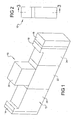
- a proportional pressure controller 10 includes a body 12 having a first end cap 14 at a first end and a second end cap 16 at an opposite and.
- First and second end caps 14, 16 can be releasably fastened or fixedly connected to body 12.
- a spacer member 18 can also be included with body 12 whose purpose will be discussed in reference to Figure 3 .
- a controller operator 20 can be connected such as by fastening or fixed connection to a central body portion 22.
- Body 12 can further include an inlet body portion 24 connected between central body portion 22 and spacer member 18, with spacer member 18 positioned between inlet body portion 24 and second end cap 16.
- Body 12 can further include an exhaust body portion 26 positioned between central body portion 22 and first end cap 14.
- proportional pressure controller 10 can be provided in the form of a generally rectangular-shaped block body such that multiple ones of the proportional pressure controllers 10 can be arranged in a side-by-side configuration. This geometry also promotes use of the proportional pressure controller 10 in a manifold configuration.
- Proportional pressure controller 10 can include each of an inlet port 28, an outlet port 30, and an exhaust port 32 each created in the central body portion 22.
- a pressurized fluid such as pressurized air can be discharged from proportional pressure controller 10 via outlet port 30 through an outlet flow passage 34. Flow to the outlet flow passage 34 can be isolated using an inlet poppet valve 36.
- Inlet poppet valve 36 is normally seated against an inlet valve seat 38 and held in the seated position shown with assist by the force of a biasing member 40 such as a compression spring, defining a controller closed condition wherein no fluid flow is discharged through either outlet or exhaust port 30, 32.
- the biasing member 40 can be held in position by contact with an end wall 41 of inlet body portion 24, and oppositely by being partially received in a valve cavity 42 of inlet poppet valve 36.
- Inlet poppet valve 36 can axially slide in each of an inlet valve closing direction "A" extending biasing member 40 and an opposite inlet valve opening direction “B” compressing biasing member 40.
- inlet valve stem 43 Oppositely directed from valve cavity 42 is an inlet valve stem 43 integrally and axially extending from inlet poppet valve 36 and coaxially aligned with biasing member 40.
- a free end of inlet valve stem 43 contacts a piston 44.
- Inlet valve stem 43 is slidably disposed through a first boundary wall 45 before contacting piston 44 to help control an axial alignment of inlet poppet valve 36 to promote a perimeter seal of a poppet seat ring 46 with inlet valve seat 38 in the closed position.
- Pressurized fluid can free-flow through first boundary wall 45 via at least one hole 47 and/or through the bore that permits passage of inlet valve stem 43.
- a size and quantity of the at least one hole 47 controls the time required for pressure in outlet flow passage 34 to act on piston 44 (on the left side as viewed in Figure 3 ) and therefore the speed of piston movement.
- the pressure acting through the at least one hole 47 creates a pressure biasing force acting to move piston 44 toward the closed position.
- Piston 44 can be provided with at least one and according to several embodiments a plurality of resilient U-cup seals 48 which are individually received in individual seal grooves 49 created about a perimeter of piston 44.
- U-cup seals 48 provide a fluid pressure seal about piston 44 as piston 44 axially slides within a cylinder cavity 50.
- Piston 44 moves coaxially with the inlet poppet valve 36 in inlet valve closing direction "A" or the inlet valve opening direction "B".
- First boundary wall 45 defines a first boundary (a non-pressure boundary) and piston 44 defines a second boundary (a pressure boundary) of a cylinder cavity 50 which slidingly receives piston 44.
- Piston 44 can move in the inlet valve opening direction "B" until an end 51 of piston 44 contacts first boundary wall 45 (at a right hand facing side of first boundary wall 45 as seen in Figure 3 ) with first boundary wall 45 being fixed in position.
- Piston 44 is retained within cylinder cavity 50 by contact with first boundary wall 45 by the previously described pressure biasing force created by pressurized fluid freely flowing through the holes 47.
- Piston 44 is also retained within cylinder cavity 50 by contact at an opposite end of cylinder cavity 50 with portions of spacer member 18 which extend radially past a cylindrical wall of cylinder cavity 50 as shown.
- An elastic seal member 52 such as an O-ring can be positioned within a slot or circumferential groove 53 created externally about a perimeter of inlet poppet valve 36.
- Elastic seal member 52 provides a relief capacity for pressurized fluid in valve cavity 42 which will be further described in reference to Figure 5 .
- Proportional pressure controller 10 can be operated using each of an inlet or fill valve 54 and a dump valve 56 which can be releasably connected to central body portion 22 within controller operator 20.
- Pressurized fluid such as pressurized air received in inlet port 28 is commonly filtered or purified. Fluid that can back-flow into proportional pressure controller 10 via outlet port 30 and outlet flow passage 34 is potentially contaminated fluid.
- the fill and dump valves 54, 56 are isolated from the potentially contaminated fluid such that only the filtered air or fluid received via inlet port 28 flows through either fill valve 54 or dump valve 56.
- An inlet flow passage 58 communicates between inlet port 28 and outlet flow passage 34 and is isolated from outlet flow passage 34 by inlet poppet valve 36 which can be normally closed.
- An air supply port 60 communicates with inlet flow passage 58 and via a fill inlet passage 62 which is isolated from outlet flow passage 34, provides pressurized fluid or air to fill valve 54.
- a valve discharge passage 64 provides a path for air flowing through fill valve 54 to be directed to an inlet of dump valve 56 and a plurality of different passages.
- One of these passages includes a piston pressurization passage 66 which directs air or fluid from valve discharge passage 64 to a piston pressurization chamber 68 created in second end cap 16. Pressurized air or fluid in piston pressurization chamber 68 generates a force acting on a piston end face 70 of piston 44.
- a surface area of piston end face 70 is larger than a surface area of inlet poppet valve 36 in contact with inlet valve seat 38, therefore, when fill valve 54 opens or continues to open further, the net force created by the pressurized fluid acting on piston end face 70 causes piston 44 to initially move or move further in the inlet valve opening direction "B" and away from inlet valve seat 38.
- Proportional pressure controller 10 can initiate flow of pressurized fluid between inlet port 28 and outlet port 30 if no flow is present at outlet port 30, or proportional pressure controller 10 can maintain, increase, or decrease the pressure of an existing flow of the pressurized fluid between inlet port 28 and outlet port 30 in those situations where a continuous regulated flow of pressurized fluid is required.
- a portion of the pressurized fluid discharged through fill valve 54 through valve discharge passage 64 is directed via an exhaust valve pressurization passage 72 created in a connecting wall 74 of central body portion 22 into an exhaust valve pressurization chamber 76.
- exhaust valve pressurization passage 72 acts against an exhaust valve end face 78 of an exhaust poppet valve 80 to retain exhaust poppet valve 80 in a seated position shown.
- Exhaust poppet valve 80 includes an exhaust poppet valve seat ring 83 which contacts an exhaust valve seat 84 in the seated position of exhaust poppet valve 80.
- exhaust poppet valve 80 When exhaust poppet valve 80 is in the seated position shown in Figure 3 , pressurized fluid flowing from outlet flow passage 34 through outlet port 30 which also enters an exhaust/outlet common passage 86 is isolated from exhaust port 32 to prevent pressurized flow out of exhaust port 32 through an exhaust flow passage 88.
- Exhaust poppet valve 80 includes an integrally connected, axially extending exhaust valve stem 90 which is slidingly received in a stem receiving passage 92 of a stem receiving member 94.
- Stem receiving member 94 is positioned between a second boundary wall 96 and the first end cap 14. Similar to first boundary wall 45, pressurized fluid can free-flow through second boundary wall 96 via at least one hole 97. A size and quantity of the hole(s) 97 controls the speed at which pressure balances across second boundary wall 96.
- a dump valve passage 98 is provided at a discharge side of dump valve 56 which communicates via a dump valve exhaust port 100 of central body portion 22 with exhaust flow passage 88. It is noted that dump valve outlet passage 98 is isolated from and therefore does not provide fluid communication with exhaust valve pressurization passage 72, valve discharge passage 64, or piston pressurization passage 66.
- each of the valve discharge passage 64, piston pressurization passage 66, exhaust valve pressurization passage 72, and dump valve passage 98 are isolated from fluid pressure in outlet flow passage 34 or exhaust/outlet common passage 86 when fill valve 54 is open. These flow passages therefore allow communication of the filtered air or fluid from inlet port 28 to be communicated through either fill or dump valve 54, 56 without exposing the fill or dump valves 54, 56 to potentially contaminated fluid in outlet port 30.
- Proportional pressure controller 10 can further include a circuit board 101 positioned within controller operator 20 which is in electrical communication with both fill and dump valves 54, 56. Signals received at circuit board 101 for positioning control of either fill or dump valve 54, 56 are received via a wiring harness 102 in controller operator 20 which is sealed using a connecting plug 104. A remotely positioned control system 106 performs calculation functions and forwards command signals to circuit board 101 which controls either/both fill and/or dump valves 54, 56 to control a system pressure at outlet port 30. Control signals from and to proportional pressure controller 10 and control system 106 are communicated using a control signal interface 108.
- Control signal interface 108 can be a hard wire (e.g.: wiring harness) connection, a wireless (e.g.: radio frequency or infra red) connection, or the like.
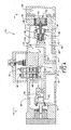
- the controller closed condition shown in Figure 3 for proportional pressure controller 10 is provided when both fill and dump valves 54, 56 are closed having inlet poppet valve 36 seated against inlet valve seat 38, and exhaust poppet valve 80 seated against exhaust valve seat 84.
- the configuration shown in Figure 3 is not limiting.
- the inlet poppet valve 36 and exhaust valve poppet valve 80 are shown in an opposed configuration, these poppet valves can be arranged in any configuration at the discretion of the manufacturer. Alternate configurations can provide the poppet valves in a side-by-side parallel disposition.
- the poppet valves can also be oriented such that both poppet valves seat in a same axial direction and unseat in the same opposed axial direction.
- the configuration shown in Figure 3 is therefore exemplary of one possible configuration.
- the configuration shown in Figure 3 indicates either a closed configuration, with no inlet pressure in communication with outlet port 30, or a pressure achieved condition which occurs when a desired pressure at outlet port 30 is reached but further flow is at least temporarily not required through outlet port 30.
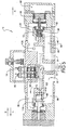
- Figure 4 can also depict the pressure achieved condition, occurring when a steady state flow of fluid at a desired pressure is achieved through outlet port 30.
- the pressure achieved condition can occur at any position of inlet poppet valve 36 with respect to inlet valve seat 38 between and including a seated and a fully open position.
- the controller open condition or pressurizing configuration of proportional pressure controller 10 is shown.
- a signal is received to open fill valve 54, with dump valve 56 being retained in a closed position.
- fill valve 54 opens, a portion of the air or fluid in inlet port 28 flows through fill valve 54 via the pilot air supply port 60 and the fill inlet passage 62. This airflow exits fill valve 54 into value discharge passage 64.
- the pressure of the fluid in valve discharge passage 64 is sensed by a pressure sensor such as a first pressure signaling device 110, which according to several embodiments can be a pressure transducer.
- valve discharge passage 64 is directed in part through piston pressurization passage 66 into piston pressurization chamber 68 to force piston 44 to slide in the inlet valve opening direction "B" which acts against inlet valve stem 43 to push inlet poppet valve 36 away from inlet valve seat 38, compressing biasing member 40.
- This opening motion of.inlet poppet valve 36 creates an inlet flow ring 111 allowing pressurized fluid in inlet flow passage 58 to flow via inlet flow ring 111 into outlet flow passage 34 and from there as shown by the various flow arrows out of proportional pressure controller 10 through outlet port 30.
- a first orifice 112 can be provided to permit fluid on the valve cavity 42 side of inlet poppet valve 36 to displace into the outlet flow passage 34 at a controlled rate permitting the sliding speed and therefore the opening timing of inlet poppet valve 36 to be predetermined.
- Pressurized fluid which exits outlet port 30 can be directed to a pressure actuated device 114 such as a piston operator or similar actuating device.
- First orifice 112 also allows pressure that is in outlet flow passage 34 to act on the spring side of poppet valve 36 creating additional biasing force toward the closed position.
- First boundary wall 45 can also function as a contact surface stopping the sliding motion of piston 44 in the inlet valve opening direction "B".
- a length of time that inlet poppet valve 36 is in the open position can be used together with the pressure sensed by first pressure signaling device 110 to proportionally control the pressure at pressure actuating device 114. Because first pressure signaling device 110 is also positioned within valve discharge passage 64, first pressure signaling device 110 is also isolated form potential contaminants that may be present in outlet port 30. This reduces the possibility of contaminants affecting the pressure signal of first pressure signaling device 110.
- valve discharge passage 64 when pressurized fluid is being discharged through outlet port 30 and when fill valve 54 is in the open position, pressurized fluid from valve discharge passage 64 is received via exhaust valve pressurization passage 72 in exhaust valve pressurization chamber 76 to retain the exhaust poppet valve 80 in its seated position by forcing the exhaust poppet valve 80 in the exhaust valve closing direction "C".
- fill valve 54 when a desired pressure is reached at pressure actuated device 114 as sensed by first pressure signaling device 110, fill valve 54 is directed to close and dump valve 56 can be directed to open. Dump valve 56 will also open if the pressure reaches a predetermined (high) pressure or the command signal is given to lower the pressure.
- fill valve 54 When fill valve 54 is in the closed position, pressurized fluid in the fill inlet passage 62 is isolated from the valve discharge passage 64.
- dump valve 56 opens, exhaust valve pressurization passage 72 vents to exhaust flow passage 88 via valve discharge passage 64 and dump valve outlet passage 98.
- the at least one hole 47 provided through first boundary wall 45 permits fluid pressure equalization across first boundary wall 45 increasing the sliding speed of piston 44 when inlet poppet valve 36 closes.
- Inlet poppet valve 36 can also be in the closed condition if the desired pressure at outlet port 30 is reached and is static.
- an exhaust flow ring 116 opens to allow flow in the direction of the multiple flow arrows shown from exhaust/outlet common passage 86 through exhaust flow ring 116, into exhaust flow passage 88, and exiting via exhaust port 32.
- the signal to open dump valve 56 is also received when the pressure at pressure actuated device 114 exceeds the desired pressure setting.
- Pressured balanced exhaust poppet valve 80 is therefore opened which allows rapid depressurization via exhaust/outlet common passage 86, exhaust flow ring 116, exhaust flow passage 88, and exhaust port 32.
- the dump valve outlet passage 98, depressurizing valve discharge passage 64, piston pressurization passage 66, piston pressurization chamber 68, and exhaust valve pressurization passage 72 also depressurize via exhaust port 32.
- a proportional pressure controller 120 is modified from proportional pressure controller 10 to provide a different type of fill valve 122 and dump valve 124.
- fill valve 122 and dump valve 124 can be hydraulically operated, solenoid operated, or air operated valves which can provide different operating characteristics for proportional pressure controller 120.
- Proportional pressure controller 120 can further include a second pressure sensor such as a second pressure signaling device 126 such as a pressure transducer positioned in outlet flow passage 34'. The addition of second pressure signaling device 126 can provide an additional/heightened sensitivity pressure detection signal at outlet port 30'.
- proportional pressure controller 120 Using the output or pressure signals received from both first pressure signaling device 110 and second pressure signaling device 126 can provide for finer position and/or open/close timing control of the valve members of proportional pressure controller 120 to mitigate either failing to reach or exceeding the desired pressure at outlet port 30'.
- the remaining components of proportional pressure controller 120 are substantially the same as those described with reference to proportional pressure controller 10 of Figure 3 . Failing to achieve the desired pressure at the outlet port of known proportional pressure control devices can result in rapid opening/closing operation of the control valves, known as "motor boating", as the controller attempts to correct to the desired pressure by moving solenoid operated valves in response to a pressure signal.
- first and second pressure signaling devices 110', 126 can provide a differential pressure between the inlet pressure sensed by first pressure signaling device 110', and the pressure at outlet port 30' which is sensed by second pressure signaling device 126, which together provide a real time difference between the desired outlet pressure and the pilot pressure.
- proportional pressure controller 120 can help mitigate the chance of motor boating.
- a proportional pressure controller 128 can include a central body portion 130 which is modified from central body portion 22, and can include an inlet body portion 131 which is modified from the inlet body portion 24 shown in Figure 3 .
- Inlet poppet valve 36' is provided with a U-cup seal member 132 and is slidably disposed in an inlet poppet valve pressure chamber 134.
- Pressurized fluid which exits inlet poppet valve pressure chamber 134 as inlet poppet valve 36' moves in inlet valve opening direction "B" is discharged via a fist orifice 112' which can be modified at the discretion of the manufacturer to change the flow characteristics of the fluid exiting from inlet poppet valve pressure chamber 134 thereby affecting the operating speed of inlet poppet valve 36'.
- An outlet flow passage orifice 136 created in central body portion 130 can further be used to control the fluid flow rate from outlet flow passage 34' to outlet port 30".
- the combination of first orifice 112' and outlet flow passage orifice 136 can be used to increase or decrease the flow rate of pressurized fluid via outlet port 30".
- valve type that is less susceptible to operating problems from the contaminates present in outlet port 30" can reduce the need for a second U-cup seal in piston 44' such that only single U-cup seal 48' can be used. This can further reduce friction associated with the sliding motion of piston 44' to further enhance the operating speed of inlet poppet valve 36'.
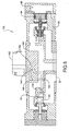
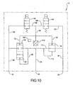
- a proportional pressure controller 138 can include a central body portion 140 modified with respect to the central body portion.
- Proportional pressure controller 138 can include a 3-way valve 142 used in place of the fill and dump valves of the previous embodiments.
- a pilot air outlet passage 144 communicating through 3-way valve 142 can similarly direct pressurized fluid via piston pressurization passage 66' to piston pressurization chamber 68 and piston 44. Pressurized fluid from pilot air outlet passage 144 can also be directed via an exhaust valve pressurization passage 146 into exhaust valve pressurization chamber 76' to fully seat exhaust poppet valve 80'.
- a separate dump pressure passage 148 communicating with 3-way valve 142 can also vent pressurized fluid via dump valve exhaust port 100' to exhaust port 32'.
- a pilot air or fluid inlet passage 150 can be created in central body portion 140 to eliminate the need for a separate internal passage providing pilot air to 3-way valve 142. Operation of proportional pressure controller 138 is otherwise similar to the previously described proportional pressure controllers herein.
- Proportional pressure controller 152 includes a central body portion 154 also modified from the central body portion 22 shown and described in reference to Figure 3 to include only a pilot air receiving passage 156 which communicates via a pilot air outlet passage 158 to both a piston pressurization passage 160 and an exhaust poppet pressurization passage 162.
- Proportional pressure controller 152 eliminates all controller mounted actuating valves and retains only the poppet valves of the previously discussed designs. This permits the space envelope of proportional pressure controller 152 to be minimized and provides for complete remote control of proportional pressure controller 152.
- proportional pressure controller 10 can provide the first pressure signaling device 110 within the valve discharge outlet passage 64 to isolate the first pressure signaling device 110 from contaminated fluid in the outlet flow passage 34, which helps mitigate against contamination effecting the pressure signal 164 or the timing of generation of the pressure signal 164.
- a signal to open fill valve 54 provides flow of pressurized fluid in fill inlet passage 62 to the inlet poppet valve 36 via piston pressurization passage 66, and also provides flow of pressurized fluid to exhaust valve end face 78 of exhaust poppet valve 80 via exhaust valve pressurization passage 72.
- Pressurized fluid discharged from fill valve 56 immediately discharges through a fill valve discharge port 166 which communicates with both valve discharge outlet passage 64 and a dump valve inlet port 168. Pressurized fluid at dump valve inlet port 168 can be blocked by the dump valve 56 from entering dump valve outlet passage 98 and discharging via exhaust port 32 unless dump valve 56 is closed.
- Proportional pressure controllers of the present disclosure offer several advantages. By eliminating solenoid actuators associated with the main flow valves of the controller and replacing the valves with poppet valves, small and lower energy consumption pilot valves in the form of fill and dump valves are used to provide pressure actuation to open or close the poppet valves. This reduces the cost and operating power required for the controller.
- the use of passageways created in the body of the controller to transfer pressurized fluid to actuate the poppet valves which are isolated from the main poppet valve flow paths prevents potentially contaminated fluid at the outlet of the controller from back-flowing into the pilot valves, which could inhibit their operation.
- One of the passageways can be used to simultaneously provide pressure to open one of the poppet valves while holding the second poppet valve in a closed position.
- the pressure sensing device By positioning a pressure sensing device in one of the isolated passageways, the pressure sensing device is also isolated from contaminants to improve the accuracy of the device's pressure signal.
- the fill and dump valves can be provided in multiple valve forms, including solenoid actuated valves, hydraulically actuated valves, and a 3-way valve replacing both the fill and dump valves.
Landscapes
- Engineering & Computer Science (AREA)
- General Engineering & Computer Science (AREA)
- Mechanical Engineering (AREA)
- Physics & Mathematics (AREA)
- Fluid Mechanics (AREA)
- Fluid-Driven Valves (AREA)
- Control Of Fluid Pressure (AREA)
- Multiple-Way Valves (AREA)
- Safety Valves (AREA)
Priority Applications (1)
| Application Number | Priority Date | Filing Date | Title |
|---|---|---|---|
| PL10193281T PL2354562T3 (pl) | 2010-01-27 | 2010-12-01 | Proporcjonalny regulator ciśnienia |
Applications Claiming Priority (1)
| Application Number | Priority Date | Filing Date | Title |
|---|---|---|---|
| US12/694,703 US8333218B2 (en) | 2010-01-27 | 2010-01-27 | Proportional pressure controller |
Publications (3)
| Publication Number | Publication Date |
|---|---|
| EP2354562A2 EP2354562A2 (en) | 2011-08-10 |
| EP2354562A3 EP2354562A3 (en) | 2013-12-18 |
| EP2354562B1 true EP2354562B1 (en) | 2014-10-29 |
Family
ID=43982220
Family Applications (1)
| Application Number | Title | Priority Date | Filing Date |
|---|---|---|---|
| EP20100193281 Active EP2354562B1 (en) | 2010-01-27 | 2010-12-01 | Proportional pressure controller |
Country Status (16)
| Country | Link |
|---|---|
| US (1) | US8333218B2 (ja) |
| EP (1) | EP2354562B1 (ja) |
| JP (1) | JP5702168B2 (ja) |
| KR (1) | KR101462710B1 (ja) |
| CN (1) | CN102135196B (ja) |
| AU (1) | AU2010257403C1 (ja) |
| BR (1) | BRPI1100737A2 (ja) |
| CA (1) | CA2726380C (ja) |
| ES (1) | ES2525730T3 (ja) |
| HK (1) | HK1156383A1 (ja) |
| MX (1) | MX2010013803A (ja) |
| NZ (1) | NZ590214A (ja) |
| PL (1) | PL2354562T3 (ja) |
| PT (1) | PT2354562E (ja) |
| TW (1) | TWI471712B (ja) |
| ZA (1) | ZA201009007B (ja) |
Families Citing this family (8)
| Publication number | Priority date | Publication date | Assignee | Title |
|---|---|---|---|---|
| US9441587B2 (en) | 2012-12-18 | 2016-09-13 | Caterpillar Inc. | Pressure regulator having an integrated check valve |
| US9611871B2 (en) * | 2013-09-13 | 2017-04-04 | Norbert J. Kot | Pneumatic valve assembly and method |
| US9903395B2 (en) * | 2016-02-24 | 2018-02-27 | Mac Valves, Inc. | Proportional pressure controller with isolation valve assembly |
| US10443707B2 (en) * | 2017-03-24 | 2019-10-15 | Borgwarner Inc. | Cooling and lubrication system including 3-way solenoid-actuated valve for automatic transmission |
| US10428842B2 (en) * | 2017-05-05 | 2019-10-01 | Aurora Flight Sciences Corporation | Pneumatic actuation systems having improved feedback control |
| KR20200097689A (ko) | 2017-12-21 | 2020-08-19 | 스웨이지락 캄파니 | 작동 밸브의 제어 및 모니터링을 위한 시스템 및 방법 |
| US11067102B1 (en) * | 2020-04-13 | 2021-07-20 | Mac Valves, Inc. | Digital proportional pressure controller |
| CN112460300A (zh) * | 2020-11-24 | 2021-03-09 | 南京工程学院 | 一种气用比例减压阀 |
Family Cites Families (25)
| Publication number | Priority date | Publication date | Assignee | Title |
|---|---|---|---|---|
| DE1067273B (ja) * | 1958-07-17 | 1959-10-15 | ||
| GB1054465A (ja) * | 1965-04-01 | |||
| US3908515A (en) * | 1973-09-10 | 1975-09-30 | Caterpillar Tractor Co | Hydraulic circuit with selectively actuatable float control |
| US4067357A (en) * | 1974-06-14 | 1978-01-10 | Herion-Werke Kg | Pilot-operated directional control valve |
| JPS5630778Y2 (ja) * | 1975-10-16 | 1981-07-22 | ||
| DE2645768C2 (de) * | 1976-10-09 | 1983-04-07 | Danfoss A/S, 6430 Nordborg | Elektrohydraulische Steuervorrichtung |
| US4111226A (en) * | 1977-08-01 | 1978-09-05 | Ross Operating Valve Co. | Multiple function four poppet valve system |
| JPS6237262A (ja) * | 1985-08-13 | 1987-02-18 | Jidosha Kiki Co Ltd | 倍力装置の圧力制御方法と装置 |
| DE3613747A1 (de) * | 1986-04-23 | 1987-10-29 | Concordia Fluidtechnik Gmbh | 5/3-ventil |
| DE3613746A1 (de) * | 1986-04-23 | 1987-10-29 | Concordia Fluidtechnik Gmbh | Ventil |
| US4878647A (en) * | 1988-09-02 | 1989-11-07 | The B. F. Goodrich Company | Pneumatic impulse valve and separation system |
| US4883091A (en) * | 1988-12-27 | 1989-11-28 | Ross Operating Valve Company | Multi-port self-regulating proportional pressure control valve |
| JP2695553B2 (ja) * | 1991-11-22 | 1997-12-24 | 株式会社ニチベイ | ブラインドの昇降回転機構 |
| US5454399A (en) * | 1993-04-08 | 1995-10-03 | Westinghouse Air Brake Company | Application and release magnet valve |
| US5361679A (en) * | 1993-04-28 | 1994-11-08 | Foster Raymond K | Directional control valve with pilot operated poppet valves |
| DE19646445A1 (de) * | 1996-11-11 | 1998-05-14 | Rexroth Mannesmann Gmbh | Ventilanordnung |
| JP2001504196A (ja) * | 1996-11-11 | 2001-03-27 | マンネスマン レックスロート アクチェンゲゼルシャフト | バルブアッセンブリ及び該バルブアッセンブリの作動方法 |
| JPH10220409A (ja) * | 1997-02-12 | 1998-08-21 | Komatsu Ltd | 方向制御弁装置 |
| US6082406A (en) * | 1997-08-11 | 2000-07-04 | Master Pneumatic - Detroit, Inc. | Pneumatic pilot-operated control valve assembly |
| JP2003003952A (ja) * | 2001-06-22 | 2003-01-08 | Noiberuku Kk | 流体吐出装置 |
| US6715402B2 (en) * | 2002-02-26 | 2004-04-06 | Husco International, Inc. | Hydraulic control circuit for operating a split actuator mechanical mechanism |
| US6772791B2 (en) * | 2002-05-17 | 2004-08-10 | Mac Valves, Inc. | Directly operated pneumatic valve having an air assist return |
| US6871574B2 (en) * | 2003-05-28 | 2005-03-29 | Husco International, Inc. | Hydraulic control valve assembly having dual directional spool valves with pilot operated check valves |
| JP4284687B2 (ja) * | 2005-04-26 | 2009-06-24 | Smc株式会社 | 真空及び真空破壊用複合弁 |
| DE102006041601A1 (de) * | 2006-09-05 | 2008-03-06 | ITW Oberflächentechnik GmbH & Co. KG | Steuereinrichtung eines Druckluftmotors, insbesondere in Kombination mit einer Pumpe und einer Sprühbeschichtungsanlage |
-
2010
- 2010-01-27 US US12/694,703 patent/US8333218B2/en active Active
- 2010-12-01 EP EP20100193281 patent/EP2354562B1/en active Active
- 2010-12-01 PT PT10193281T patent/PT2354562E/pt unknown
- 2010-12-01 ES ES10193281.2T patent/ES2525730T3/es active Active
- 2010-12-01 PL PL10193281T patent/PL2354562T3/pl unknown
- 2010-12-14 MX MX2010013803A patent/MX2010013803A/es active IP Right Grant
- 2010-12-14 ZA ZA2010/09007A patent/ZA201009007B/en unknown
- 2010-12-16 TW TW99144279A patent/TWI471712B/zh active
- 2010-12-17 CA CA2726380A patent/CA2726380C/en not_active Expired - Fee Related
- 2010-12-23 AU AU2010257403A patent/AU2010257403C1/en not_active Ceased
- 2010-12-24 NZ NZ590214A patent/NZ590214A/en not_active IP Right Cessation
-
2011
- 2011-01-25 BR BRPI1100737-0A patent/BRPI1100737A2/pt not_active Application Discontinuation
- 2011-01-26 KR KR1020110007924A patent/KR101462710B1/ko active IP Right Grant
- 2011-01-26 CN CN201110037485.8A patent/CN102135196B/zh active Active
- 2011-01-27 JP JP2011015795A patent/JP5702168B2/ja active Active
- 2011-10-11 HK HK11110755.1A patent/HK1156383A1/xx unknown
Also Published As
| Publication number | Publication date |
|---|---|
| AU2010257403C1 (en) | 2016-04-14 |
| KR101462710B1 (ko) | 2014-11-17 |
| US8333218B2 (en) | 2012-12-18 |
| US20110179946A1 (en) | 2011-07-28 |
| PT2354562E (pt) | 2014-11-06 |
| EP2354562A2 (en) | 2011-08-10 |
| MX2010013803A (es) | 2011-07-26 |
| HK1156383A1 (en) | 2012-06-08 |
| CN102135196A (zh) | 2011-07-27 |
| TW201144961A (en) | 2011-12-16 |
| ZA201009007B (en) | 2012-05-01 |
| AU2010257403B2 (en) | 2015-09-24 |
| EP2354562A3 (en) | 2013-12-18 |
| KR20110088443A (ko) | 2011-08-03 |
| CN102135196B (zh) | 2014-10-29 |
| ES2525730T3 (es) | 2014-12-29 |
| CA2726380C (en) | 2016-02-09 |
| NZ590214A (en) | 2011-10-28 |
| JP2011153709A (ja) | 2011-08-11 |
| CA2726380A1 (en) | 2011-07-27 |
| PL2354562T3 (pl) | 2015-04-30 |
| TWI471712B (zh) | 2015-02-01 |
| AU2010257403A1 (en) | 2011-08-11 |
| BRPI1100737A2 (pt) | 2015-06-30 |
| JP5702168B2 (ja) | 2015-04-15 |
Similar Documents
| Publication | Publication Date | Title |
|---|---|---|
| EP2354562B1 (en) | Proportional pressure controller | |
| EP3027941B1 (en) | A flow control system and control valve having closure assistance | |
| EP3147594B1 (en) | Valve for a refrigeration system | |
| KR20140021987A (ko) | 제어 또는 전환 밸브를 포함하는 아마추어의 작동을 위한 유압 또는 공압 구동기 | |
| EP2433042B1 (en) | Pneumatically actuated pilot valve | |
| JP6770320B2 (ja) | 環状ポペット逆止弁を備えた調節弁 | |
| EP3236086B1 (en) | Proportional pressure controller with isolation valve assembly | |
| JP2011153709A5 (ja) | ||
| EP2683949B1 (en) | Bypass arrangement for valve actuator | |
| US6604547B1 (en) | Double valve with cross exhaust | |
| NZ728806A (en) | Proportional pressure controller with isolation valve assembly | |
| US20100037762A1 (en) | Valve device and method for the activation of an actuating drive acted upon with pressure medium by a position controller | |
| EP1069323B1 (en) | Cross flow with crossmirror and lock out capability valve | |
| JPH0481075B2 (ja) |
Legal Events
| Date | Code | Title | Description |
|---|---|---|---|
| PUAI | Public reference made under article 153(3) epc to a published international application that has entered the european phase |
Free format text: ORIGINAL CODE: 0009012 |
|
| AK | Designated contracting states |
Kind code of ref document: A2 Designated state(s): AL AT BE BG CH CY CZ DE DK EE ES FI FR GB GR HR HU IE IS IT LI LT LU LV MC MK MT NL NO PL PT RO RS SE SI SK SM TR |
|
| AX | Request for extension of the european patent |
Extension state: BA ME |
|
| PUAL | Search report despatched |
Free format text: ORIGINAL CODE: 0009013 |
|
| AK | Designated contracting states |
Kind code of ref document: A3 Designated state(s): AL AT BE BG CH CY CZ DE DK EE ES FI FR GB GR HR HU IE IS IT LI LT LU LV MC MK MT NL NO PL PT RO RS SE SI SK SM TR |
|
| AX | Request for extension of the european patent |
Extension state: BA ME |
|
| RIC1 | Information provided on ipc code assigned before grant |
Ipc: F15B 13/043 20060101AFI20131108BHEP |
|
| 17P | Request for examination filed |
Effective date: 20140115 |
|
| RBV | Designated contracting states (corrected) |
Designated state(s): AL AT BE BG CH CY CZ DE DK EE ES FI FR GB GR HR HU IE IS IT LI LT LU LV MC MK MT NL NO PL PT RO RS SE SI SK SM TR |
|
| GRAP | Despatch of communication of intention to grant a patent |
Free format text: ORIGINAL CODE: EPIDOSNIGR1 |
|
| INTG | Intention to grant announced |
Effective date: 20140514 |
|
| GRAS | Grant fee paid |
Free format text: ORIGINAL CODE: EPIDOSNIGR3 |
|
| GRAA | (expected) grant |
Free format text: ORIGINAL CODE: 0009210 |
|
| AK | Designated contracting states |
Kind code of ref document: B1 Designated state(s): AL AT BE BG CH CY CZ DE DK EE ES FI FR GB GR HR HU IE IS IT LI LT LU LV MC MK MT NL NO PL PT RO RS SE SI SK SM TR |
|
| REG | Reference to a national code |
Ref country code: GB Ref legal event code: FG4D |
|
| REG | Reference to a national code |
Ref country code: CH Ref legal event code: EP |
|
| REG | Reference to a national code |
Ref country code: PT Ref legal event code: SC4A Free format text: AVAILABILITY OF NATIONAL TRANSLATION Effective date: 20141030 |
|
| REG | Reference to a national code |
Ref country code: AT Ref legal event code: REF Ref document number: 693755 Country of ref document: AT Kind code of ref document: T Effective date: 20141115 |
|
| REG | Reference to a national code |
Ref country code: IE Ref legal event code: FG4D |
|
| REG | Reference to a national code |
Ref country code: DE Ref legal event code: R096 Ref document number: 602010019794 Country of ref document: DE Effective date: 20141211 |
|
| REG | Reference to a national code |
Ref country code: ES Ref legal event code: FG2A Ref document number: 2525730 Country of ref document: ES Kind code of ref document: T3 Effective date: 20141229 |
|
| REG | Reference to a national code |
Ref country code: NL Ref legal event code: T3 |
|
| REG | Reference to a national code |
Ref country code: GR Ref legal event code: EP Ref document number: 20140402241 Country of ref document: GR Effective date: 20141223 |
|
| REG | Reference to a national code |
Ref country code: SE Ref legal event code: TRGR |
|
| REG | Reference to a national code |
Ref country code: LT Ref legal event code: MG4D |
|
| PG25 | Lapsed in a contracting state [announced via postgrant information from national office to epo] |
Ref country code: IS Free format text: LAPSE BECAUSE OF FAILURE TO SUBMIT A TRANSLATION OF THE DESCRIPTION OR TO PAY THE FEE WITHIN THE PRESCRIBED TIME-LIMIT Effective date: 20150228 Ref country code: LT Free format text: LAPSE BECAUSE OF FAILURE TO SUBMIT A TRANSLATION OF THE DESCRIPTION OR TO PAY THE FEE WITHIN THE PRESCRIBED TIME-LIMIT Effective date: 20141029 Ref country code: FI Free format text: LAPSE BECAUSE OF FAILURE TO SUBMIT A TRANSLATION OF THE DESCRIPTION OR TO PAY THE FEE WITHIN THE PRESCRIBED TIME-LIMIT Effective date: 20141029 Ref country code: NO Free format text: LAPSE BECAUSE OF FAILURE TO SUBMIT A TRANSLATION OF THE DESCRIPTION OR TO PAY THE FEE WITHIN THE PRESCRIBED TIME-LIMIT Effective date: 20150129 |
|
| REG | Reference to a national code |
Ref country code: PL Ref legal event code: T3 |
|
| PG25 | Lapsed in a contracting state [announced via postgrant information from national office to epo] |
Ref country code: CY Free format text: LAPSE BECAUSE OF FAILURE TO SUBMIT A TRANSLATION OF THE DESCRIPTION OR TO PAY THE FEE WITHIN THE PRESCRIBED TIME-LIMIT Effective date: 20141029 Ref country code: HR Free format text: LAPSE BECAUSE OF FAILURE TO SUBMIT A TRANSLATION OF THE DESCRIPTION OR TO PAY THE FEE WITHIN THE PRESCRIBED TIME-LIMIT Effective date: 20141029 Ref country code: LV Free format text: LAPSE BECAUSE OF FAILURE TO SUBMIT A TRANSLATION OF THE DESCRIPTION OR TO PAY THE FEE WITHIN THE PRESCRIBED TIME-LIMIT Effective date: 20141029 Ref country code: RS Free format text: LAPSE BECAUSE OF FAILURE TO SUBMIT A TRANSLATION OF THE DESCRIPTION OR TO PAY THE FEE WITHIN THE PRESCRIBED TIME-LIMIT Effective date: 20141029 |
|
| REG | Reference to a national code |
Ref country code: DE Ref legal event code: R097 Ref document number: 602010019794 Country of ref document: DE |
|
| PG25 | Lapsed in a contracting state [announced via postgrant information from national office to epo] |
Ref country code: EE Free format text: LAPSE BECAUSE OF FAILURE TO SUBMIT A TRANSLATION OF THE DESCRIPTION OR TO PAY THE FEE WITHIN THE PRESCRIBED TIME-LIMIT Effective date: 20141029 Ref country code: RO Free format text: LAPSE BECAUSE OF FAILURE TO SUBMIT A TRANSLATION OF THE DESCRIPTION OR TO PAY THE FEE WITHIN THE PRESCRIBED TIME-LIMIT Effective date: 20141029 Ref country code: SK Free format text: LAPSE BECAUSE OF FAILURE TO SUBMIT A TRANSLATION OF THE DESCRIPTION OR TO PAY THE FEE WITHIN THE PRESCRIBED TIME-LIMIT Effective date: 20141029 Ref country code: DK Free format text: LAPSE BECAUSE OF FAILURE TO SUBMIT A TRANSLATION OF THE DESCRIPTION OR TO PAY THE FEE WITHIN THE PRESCRIBED TIME-LIMIT Effective date: 20141029 |
|
| REG | Reference to a national code |
Ref country code: CH Ref legal event code: PL |
|
| PLBE | No opposition filed within time limit |
Free format text: ORIGINAL CODE: 0009261 |
|
| STAA | Information on the status of an ep patent application or granted ep patent |
Free format text: STATUS: NO OPPOSITION FILED WITHIN TIME LIMIT |
|
| REG | Reference to a national code |
Ref country code: IE Ref legal event code: MM4A |
|
| 26N | No opposition filed |
Effective date: 20150730 |
|
| PG25 | Lapsed in a contracting state [announced via postgrant information from national office to epo] |
Ref country code: LI Free format text: LAPSE BECAUSE OF NON-PAYMENT OF DUE FEES Effective date: 20141231 Ref country code: CH Free format text: LAPSE BECAUSE OF NON-PAYMENT OF DUE FEES Effective date: 20141231 Ref country code: IE Free format text: LAPSE BECAUSE OF NON-PAYMENT OF DUE FEES Effective date: 20141201 |
|
| REG | Reference to a national code |
Ref country code: FR Ref legal event code: PLFP Year of fee payment: 6 |
|
| PG25 | Lapsed in a contracting state [announced via postgrant information from national office to epo] |
Ref country code: SI Free format text: LAPSE BECAUSE OF FAILURE TO SUBMIT A TRANSLATION OF THE DESCRIPTION OR TO PAY THE FEE WITHIN THE PRESCRIBED TIME-LIMIT Effective date: 20141029 |
|
| PG25 | Lapsed in a contracting state [announced via postgrant information from national office to epo] |
Ref country code: SM Free format text: LAPSE BECAUSE OF FAILURE TO SUBMIT A TRANSLATION OF THE DESCRIPTION OR TO PAY THE FEE WITHIN THE PRESCRIBED TIME-LIMIT Effective date: 20141029 |
|
| PG25 | Lapsed in a contracting state [announced via postgrant information from national office to epo] |
Ref country code: MC Free format text: LAPSE BECAUSE OF FAILURE TO SUBMIT A TRANSLATION OF THE DESCRIPTION OR TO PAY THE FEE WITHIN THE PRESCRIBED TIME-LIMIT Effective date: 20141029 |
|
| PG25 | Lapsed in a contracting state [announced via postgrant information from national office to epo] |
Ref country code: BG Free format text: LAPSE BECAUSE OF FAILURE TO SUBMIT A TRANSLATION OF THE DESCRIPTION OR TO PAY THE FEE WITHIN THE PRESCRIBED TIME-LIMIT Effective date: 20141029 |
|
| PG25 | Lapsed in a contracting state [announced via postgrant information from national office to epo] |
Ref country code: MT Free format text: LAPSE BECAUSE OF FAILURE TO SUBMIT A TRANSLATION OF THE DESCRIPTION OR TO PAY THE FEE WITHIN THE PRESCRIBED TIME-LIMIT Effective date: 20141029 Ref country code: HU Free format text: LAPSE BECAUSE OF FAILURE TO SUBMIT A TRANSLATION OF THE DESCRIPTION OR TO PAY THE FEE WITHIN THE PRESCRIBED TIME-LIMIT; INVALID AB INITIO Effective date: 20101201 |
|
| REG | Reference to a national code |
Ref country code: FR Ref legal event code: PLFP Year of fee payment: 7 |
|
| PG25 | Lapsed in a contracting state [announced via postgrant information from national office to epo] |
Ref country code: IT Free format text: LAPSE BECAUSE OF NON-PAYMENT OF DUE FEES Effective date: 20151201 |
|
| PG25 | Lapsed in a contracting state [announced via postgrant information from national office to epo] |
Ref country code: IT Free format text: LAPSE BECAUSE OF NON-PAYMENT OF DUE FEES Effective date: 20151201 |
|
| PGRI | Patent reinstated in contracting state [announced from national office to epo] |
Ref country code: IT Effective date: 20170710 |
|
| REG | Reference to a national code |
Ref country code: FR Ref legal event code: PLFP Year of fee payment: 8 |
|
| PG25 | Lapsed in a contracting state [announced via postgrant information from national office to epo] |
Ref country code: MK Free format text: LAPSE BECAUSE OF FAILURE TO SUBMIT A TRANSLATION OF THE DESCRIPTION OR TO PAY THE FEE WITHIN THE PRESCRIBED TIME-LIMIT Effective date: 20141029 |
|
| PG25 | Lapsed in a contracting state [announced via postgrant information from national office to epo] |
Ref country code: AL Free format text: LAPSE BECAUSE OF FAILURE TO SUBMIT A TRANSLATION OF THE DESCRIPTION OR TO PAY THE FEE WITHIN THE PRESCRIBED TIME-LIMIT Effective date: 20141029 |
|
| PGFP | Annual fee paid to national office [announced via postgrant information from national office to epo] |
Ref country code: NL Payment date: 20191226 Year of fee payment: 10 Ref country code: SE Payment date: 20191227 Year of fee payment: 10 Ref country code: CZ Payment date: 20191121 Year of fee payment: 10 Ref country code: PT Payment date: 20191120 Year of fee payment: 10 |
|
| PGFP | Annual fee paid to national office [announced via postgrant information from national office to epo] |
Ref country code: LU Payment date: 20191227 Year of fee payment: 10 Ref country code: PL Payment date: 20191119 Year of fee payment: 10 Ref country code: IT Payment date: 20191219 Year of fee payment: 10 Ref country code: GR Payment date: 20191230 Year of fee payment: 10 Ref country code: FR Payment date: 20191226 Year of fee payment: 10 |
|
| PGFP | Annual fee paid to national office [announced via postgrant information from national office to epo] |
Ref country code: AT Payment date: 20191120 Year of fee payment: 10 Ref country code: TR Payment date: 20191120 Year of fee payment: 10 |
|
| PGFP | Annual fee paid to national office [announced via postgrant information from national office to epo] |
Ref country code: DE Payment date: 20191231 Year of fee payment: 10 Ref country code: GB Payment date: 20200102 Year of fee payment: 10 Ref country code: ES Payment date: 20200102 Year of fee payment: 10 |
|
| PGFP | Annual fee paid to national office [announced via postgrant information from national office to epo] |
Ref country code: BE Payment date: 20191227 Year of fee payment: 10 |
|
| REG | Reference to a national code |
Ref country code: DE Ref legal event code: R119 Ref document number: 602010019794 Country of ref document: DE |
|
| PG25 | Lapsed in a contracting state [announced via postgrant information from national office to epo] |
Ref country code: CZ Free format text: LAPSE BECAUSE OF NON-PAYMENT OF DUE FEES Effective date: 20201201 Ref country code: PT Free format text: LAPSE BECAUSE OF NON-PAYMENT OF DUE FEES Effective date: 20210601 |
|
| REG | Reference to a national code |
Ref country code: SE Ref legal event code: EUG |
|
| REG | Reference to a national code |
Ref country code: NL Ref legal event code: MM Effective date: 20210101 |
|
| REG | Reference to a national code |
Ref country code: AT Ref legal event code: MM01 Ref document number: 693755 Country of ref document: AT Kind code of ref document: T Effective date: 20201201 |
|
| GBPC | Gb: european patent ceased through non-payment of renewal fee |
Effective date: 20201201 |
|
| REG | Reference to a national code |
Ref country code: BE Ref legal event code: MM Effective date: 20201231 |
|
| PG25 | Lapsed in a contracting state [announced via postgrant information from national office to epo] |
Ref country code: NL Free format text: LAPSE BECAUSE OF NON-PAYMENT OF DUE FEES Effective date: 20210101 |
|
| PG25 | Lapsed in a contracting state [announced via postgrant information from national office to epo] |
Ref country code: LU Free format text: LAPSE BECAUSE OF NON-PAYMENT OF DUE FEES Effective date: 20201201 Ref country code: FR Free format text: LAPSE BECAUSE OF NON-PAYMENT OF DUE FEES Effective date: 20201231 Ref country code: AT Free format text: LAPSE BECAUSE OF NON-PAYMENT OF DUE FEES Effective date: 20201201 |
|
| PG25 | Lapsed in a contracting state [announced via postgrant information from national office to epo] |
Ref country code: GR Free format text: LAPSE BECAUSE OF NON-PAYMENT OF DUE FEES Effective date: 20210707 Ref country code: SE Free format text: LAPSE BECAUSE OF NON-PAYMENT OF DUE FEES Effective date: 20201202 Ref country code: GB Free format text: LAPSE BECAUSE OF NON-PAYMENT OF DUE FEES Effective date: 20201201 Ref country code: DE Free format text: LAPSE BECAUSE OF NON-PAYMENT OF DUE FEES Effective date: 20210701 |
|
| REG | Reference to a national code |
Ref country code: ES Ref legal event code: FD2A Effective date: 20220214 |
|
| PG25 | Lapsed in a contracting state [announced via postgrant information from national office to epo] |
Ref country code: ES Free format text: LAPSE BECAUSE OF NON-PAYMENT OF DUE FEES Effective date: 20201202 |
|
| PG25 | Lapsed in a contracting state [announced via postgrant information from national office to epo] |
Ref country code: BE Free format text: LAPSE BECAUSE OF NON-PAYMENT OF DUE FEES Effective date: 20201231 |
|
| PG25 | Lapsed in a contracting state [announced via postgrant information from national office to epo] |
Ref country code: PL Free format text: LAPSE BECAUSE OF NON-PAYMENT OF DUE FEES Effective date: 20201201 |
|
| PG25 | Lapsed in a contracting state [announced via postgrant information from national office to epo] |
Ref country code: IT Free format text: LAPSE BECAUSE OF NON-PAYMENT OF DUE FEES Effective date: 20201201 |