EP2353790B1 - Handgeführter Bohrhammer - Google Patents
Handgeführter Bohrhammer Download PDFInfo
- Publication number
- EP2353790B1 EP2353790B1 EP10196701.6A EP10196701A EP2353790B1 EP 2353790 B1 EP2353790 B1 EP 2353790B1 EP 10196701 A EP10196701 A EP 10196701A EP 2353790 B1 EP2353790 B1 EP 2353790B1
- Authority
- EP
- European Patent Office
- Prior art keywords
- region
- rotation
- cross
- hammer drill
- axis
- Prior art date
- Legal status (The legal status is an assumption and is not a legal conclusion. Google has not performed a legal analysis and makes no representation as to the accuracy of the status listed.)
- Not-in-force
Links
- 230000007246 mechanism Effects 0.000 claims description 14
- 238000005553 drilling Methods 0.000 claims description 10
- 238000004519 manufacturing process Methods 0.000 claims description 6
- 238000009527 percussion Methods 0.000 description 13
- 230000000694 effects Effects 0.000 description 9
- 238000007789 sealing Methods 0.000 description 6
- 230000010355 oscillation Effects 0.000 description 3
- 230000008901 benefit Effects 0.000 description 2
- 230000001419 dependent effect Effects 0.000 description 2
- 230000003213 activating effect Effects 0.000 description 1
- 230000005540 biological transmission Effects 0.000 description 1
- 230000008878 coupling Effects 0.000 description 1
- 238000010168 coupling process Methods 0.000 description 1
- 238000005859 coupling reaction Methods 0.000 description 1
- 230000010349 pulsation Effects 0.000 description 1
- 230000009467 reduction Effects 0.000 description 1
- 230000000284 resting effect Effects 0.000 description 1
- 230000035939 shock Effects 0.000 description 1
- 230000007704 transition Effects 0.000 description 1
Images

Classifications
-
- B—PERFORMING OPERATIONS; TRANSPORTING
- B25—HAND TOOLS; PORTABLE POWER-DRIVEN TOOLS; MANIPULATORS
- B25D—PERCUSSIVE TOOLS
- B25D17/00—Details of, or accessories for, portable power-driven percussive tools
- B25D17/06—Hammer pistons; Anvils ; Guide-sleeves for pistons
-
- B—PERFORMING OPERATIONS; TRANSPORTING
- B25—HAND TOOLS; PORTABLE POWER-DRIVEN TOOLS; MANIPULATORS
- B25D—PERCUSSIVE TOOLS
- B25D2211/00—Details of portable percussive tools with electromotor or other motor drive
- B25D2211/06—Means for driving the impulse member
- B25D2211/068—Crank-actuated impulse-driving mechanisms
-
- B—PERFORMING OPERATIONS; TRANSPORTING
- B25—HAND TOOLS; PORTABLE POWER-DRIVEN TOOLS; MANIPULATORS
- B25D—PERCUSSIVE TOOLS
- B25D2217/00—Details of, or accessories for, portable power-driven percussive tools
- B25D2217/0011—Details of anvils, guide-sleeves or pistons
- B25D2217/0023—Pistons
-
- B—PERFORMING OPERATIONS; TRANSPORTING
- B25—HAND TOOLS; PORTABLE POWER-DRIVEN TOOLS; MANIPULATORS
- B25D—PERCUSSIVE TOOLS
- B25D2250/00—General details of portable percussive tools; Components used in portable percussive tools
- B25D2250/345—Use of o-rings
-
- B—PERFORMING OPERATIONS; TRANSPORTING
- B25—HAND TOOLS; PORTABLE POWER-DRIVEN TOOLS; MANIPULATORS
- B25D—PERCUSSIVE TOOLS
- B25D2250/00—General details of portable percussive tools; Components used in portable percussive tools
- B25D2250/365—Use of seals
Definitions
- the present invention relates to a hand-held hammer drill according to the preamble of claim 1.
- a hammer drill is already out, for example US 4,192,391 known.
- a hand-held hammer drill comprises a spindle which drives a tool holder in rotation about a rotation axis during drilling operation.
- the spindle itself is usually driven by means of an electric motor.
- a hammer drill usually includes a pneumatic percussion hammering in impact mode against an inserted into the tool holder tool.
- Such a percussion usually has a piston which executes strokes parallel to the axis of rotation in a stroke in a cylinder formed in the spindle.
- the strokes of the piston to generate pressure oscillations in the cylinder, with the aid of a transmission piston is also driven to lift movements to strike against a percussion piston, a so-called striker, which in turn transmits these shocks to the respective tool.
- the piston is sealed relative to the cylinder appropriate.
- the piston may have at least one annular groove in which a ring seal is arranged. Due to the stroke movement of the piston, the ring seal is exposed to high wear.
- Modern rotary hammers may also be equipped with a percussion stop that allows for drilling without impact operation.
- a percussion stop that allows for drilling without impact operation.
- this is a drive train between the spindle driving the electric motor and the percussion interrupted, for example by means of a clutch or the like.
- the piston in the cylinder does not perform any lifting movements.
- the spindle rotates about the axis of rotation and thus also about the piston.
- the impact mode is deactivated This leads to a particularly high load on the ring seal. It can become overheated and damaged. A damaged ring seal reduces the sealing effect between the piston and cylinder, which reduces the effectiveness of the pressure oscillations and thus the efficiency of the hammer drill in impact mode.
- the present invention addresses the problem of providing for such a hammer drill an improved embodiment, which is characterized in particular by a reduced wear.
- the invention is based on the general idea to match the annular groove and the ring seal so that the ring seal is movable in the annular groove parallel to the axis of rotation, wherein the annular groove has a varying groove depth parallel to the axis of rotation.
- the sealing effect between piston and cylinder depends on the contact pressure of the ring seal on the cylinder. The greater this radial contact pressure, the greater the effective frictional forces. Due to the varying groove depth and the adjustability of the ring seal in the annular groove, the ring seal can assume a position in the moving piston, in which a smaller groove depth is present, whereby the sealing effect is increased.
- the ring seal can assume a position in which there is a greater groove depth, as a result of which the friction can be significantly reduced.
- the wear of the ring seal can be reduced for the drilling operation. This reduction in wear has a particularly significant effect if, by means of an optional impact shut-off the impact mode is deactivated and the piston is permanently stationary during the drilling operation.
- a groove bottom has a maximum distance from the cylinder. Axially adjacent thereto are then smaller distances. If the ring seal is in the range of the maximum distance, it is less biased against the cylinder, whereby the friction between the annular groove and cylinder for the drilling operation is reduced without impact operation. If, however, the ring seal is located in an axial region of the cross-sectional profile with smaller distances, the contact pressure of the ring seal against the cylinder increases, which is accompanied by an increased effectiveness of the sealing effect and consequently an increase in the performance of the hammer drill for impact operation.
- the strokes of the piston cause the ring seal to move out of the central area and, depending on the stroke direction, into one or the other Area moved in with a smaller distance.
- This relative movement between ring seal and annular groove can be supported on the one hand by the inertial forces and on the other hand can be promoted by the prevailing between the ring seal and the cylinder friction.
- the ring seal within the annular groove automatically takes the positions with the smaller distances, which increases the sealing effect and thus the effectiveness of the impact mechanism.
- the cross-sectional profile of the annular groove can be configured with mirror symmetry relative to a plane of symmetry running perpendicular to the axis of rotation.
- the region with the maximum distance is then arranged centrally in the cross-sectional profile of the annular groove, while the two adjacent end regions are then the same size. This results in substantially the same effects for the ring seal for both stroke directions of the piston.
- the maximum distance in the context of manufacturing tolerances can be generated equal to or greater than a maximum diameter of the cross-section of the ring seal measured parallel to the distance between the groove base and the cylinder.
- the maximum distance is adapted to the ring seal so that the ring seal does not touch the cylinder or virtually force-free when it is in the axial region of the maximum distance. The friction is minimized.
- Fig. 1 and 2 includes a hand-held hammer drill 1 shown here only partially, in a housing 2, a spindle 3 and a pneumatic Schlagwerk 4.
- the spindle 3 is used in drilling operation for driving a tool holder 5.
- the tool holder 5 and the spindle 3 rotate about an axis of rotation 6.
- the axis of rotation 6 in the sectional plane II-II.
- the spindle 3 itself is for example with an in Fig. 1 indicated electric motor 7 is drive-coupled, which is arranged in a separate portion of the housing 2, which is omitted here for the sake of simplicity.
- the striking mechanism 4 is used in a striking operation to hammer against a tool, not shown here, which is used for this purpose in the tool holder 5.
- the hammer drill 1 may preferably be equipped with a percussion stop 8. This includes, for example, a manually operable switching element 9, with the impact mode can be turned on and off.
- a percussion stop 8 This includes, for example, a manually operable switching element 9, with the impact mode can be turned on and off.
- the percussion mechanism 4 has a piston 10 which in stroke operation in a cylinder 11 carries out lifting movements parallel to the axis of rotation 6.
- the cylinder 11 is formed in the spindle 3.
- the spindle 3 is designed to be hollow cylindrical.
- the piston 10 performs oscillating strokes corresponding to a double arrow 12, which generate pressure pulsations in the cylinder 11 in a pressure-transmitting space 13. These are transmitted to a transfer piston 14.
- This transfer piston 14 is thereby also excited to oscillating strokes parallel to the axis of rotation 6.
- the transitional piston 14 strikes against a percussion piston 15, which is also referred to as an anvil 15.
- the percussion piston 15 in turn finally strikes against the tool used in the tool holder 5 tool.
- the percussion mechanism 4 may have a crank drive 16 which couples the piston 10 via a connecting rod 17 with a drive wheel 18 which rotates with activated impact operation about a perpendicular to the axis of rotation 6 axis of rotation 19 and arranged eccentrically to the axis of rotation 19
- Carrier pin 20 for driving the connecting rod 17 carries.
- the connecting rod 17 is rotatably coupled to the piston 10.
- the piston 10 does not carry out a lifting movement, so that it stands still with respect to the axis of rotation 6.
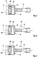
- the Fig. 3-5 is the cutting plane at 90 ° to the cutting plane of the Fig. 2 rotated, so that there the coupling between the connecting rod 17 and piston 10 via the pin 23 is better visible.
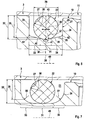
- Fig. 3-6 has the piston 10 on an outer side facing the cylinder 11 with respect to the rotation axis 6 in the circumferential direction closed circumferential annular groove 21 into which a ring seal 22 is inserted.
- the annular groove 21 has a cross-sectional profile 24 which is configured substantially U-shaped.
- This cross-sectional profile 24 lies in a cross-sectional plane which contains the axis of rotation 6.
- the cross-sectional profile 24 has two side flanks 25 and a groove bottom 26.
- the two side edges 25 are largely planar, wherein they each lie in a plane which extends perpendicular to the axis of rotation 6.
- the ring seal 22 has a cross-sectional profile 27.
- this cross-sectional profile 27 is substantially circular designed.
- the ring seal 22 is preferably an O-ring.
- the cross-sectional profile 24 of the annular groove 21 has a groove width 28 which is greater than a likewise measured parallel to the axis of rotation 6 width 29 of the cross-sectional profile 27 of the ring seal 22.
- the Ring seal 22 within the annular groove 21 axially, that is parallel to the axis of rotation 6 adjustable, which in Fig. 6 indicated by a double arrow 30.
- the cross-sectional profile 24 of the annular groove 21 has an axial region 31, in which the groove base 26 from the cylinder 11 has a maximum distance 32. Furthermore, the groove base 26 has at least one further axial region 33, 34, in which the groove base 26 has at least a smaller distance 35 from the cylinder 11, that is to say at least a distance 35 which is smaller than the maximum distance 32.
- Fig. 6 has the cross-sectional profile 24 of the annular groove 21 parallel to the rotation axis 6 on both sides of the maximum distance 32 having region 31 each have a region 33 and 34 with the at least one smaller distance 35. Consequently, the maximum distance 32 provided with an area 31 between the two other areas 33, 34, so that it is also referred to below as the central region 31, while the others are also referred to below as end regions 33, 34.
- the in Fig. 6 shown symmetrical configuration of the annular groove 21 and its cross-sectional profile 24.
- the cross-sectional profile 24 of Ring groove 21 with respect to a plane of symmetry 36 which extends perpendicular to the axis of rotation 6, designed mirror-symmetrically.
- Fig. 6 other special features that can be realized optionally.
- the central region 31 of the groove base 26 is concavely curved toward the ring seal 22.
- a circular arc-shaped curvature can be realized here. It is then particularly advantageous to choose an arc radius 37 of this arcuate central region 31 that is larger than a circle radius 38 of the circular cross-sectional profile 27 of the ring seal 22.
- the end portions 33, 34 are preferably shaped so as to be rectilinear in at least a substantial portion.
- These rectilinear sections are in Fig. 6 denoted by 39 and 40, respectively.
- the rectilinear sections 39, 40 of the end regions 33, 34 enclose therebetween an obtuse angle 41, which in particular is greater than 120 ° and can have, for example, 150 ° ⁇ 10 °.
- the rectilinear sections 39, 40 of the end regions 33, 34 pass tangentially into the curved middle region 31.
- an arcuate, in particular circular arc-shaped transition 42 to the rectilinear flanks 25 of the cross-sectional profile 24 of the annular groove 21 is provided.
- Fig. 6 shows another special feature that can be realized as an option.
- the ring seal 22 is arranged in the central region 31 of the annular groove 21. It is thus located in the region of the annular groove 21, which has the largest groove depth, ie the maximum distance 32.
- This maximum distance 32 can now be chosen equal to a preferred embodiment as a diameter 43 of the cross section 27 of the ring seal 22, said diameter 43rd is measured parallel to the distance between groove base 26 and cylinder 11.
- the diameter 48 is measured parallel to the distance 32, since the originally circular cross section of the ring seal 22 under radial stress, which is also in the state of the Fig. 6 can be present, is deformed more or less oval or elliptical.
- the cross-sectional profile 24 of the annular groove 21 is parallel to the axis of rotation 6 at most 50% greater than the cross-sectional profile 27 of the ring seal 22nd
- the central region 31 is designed such that it extends in a straight line and parallel to the axial direction 49 and thus parallel to the axis of rotation 6.
- the annular groove 21 has a constant portion in the cross-sectional profile 24 in the central region 31 in the axial direction 49.
- the two end regions 33, 34 are curved and pass tangentially into the rectilinear central region 31.
- the end regions 33, 34 can be curved in a circular arc, wherein they then each have a radius 50 or 51.
- the two radii 50, 51 are suitably the same size; However, they can be different in size.
- the respective radius 50, 51 is greater than the radius 38 of the cross-sectional profile 27 of the ring seal 22, which is present at least in the relaxed state of the ring seal 22.
- the end portions 33, 34 thereby form ramps along which the ring seal 22 is lifted radially outward as the ring seal 22 moves within the annular groove 21 from the central region 31 into one of the end regions 33, 34.
- the hammer drill 1 can be connected with a cable, not shown here to a power grid. It is also possible to equip the hammer drill 1 with a battery, whereby the hammer drill 1 can be operated independently of a power grid.
- a battery is in Fig. 1 but not shown. It usually closes in relation to the presentation in Fig. 1 at the bottom of the housing 2 at.
- the ring seal 22 is driven by the inner bias of the ring seal 22, which experiences this when it is widened in the end regions 33, 34 by the ramp effect.
- This condition according to Fig. 3 can also occur when activated impact mode, and always when the piston 10 reverses the direction of movement when passing through one of its dead centers and is temporarily stationary.
Landscapes
- Engineering & Computer Science (AREA)
- Mechanical Engineering (AREA)
- Percussive Tools And Related Accessories (AREA)
Description
- Die vorliegende Erfindung betrifft einen handgeführten Bohrhammer gemäß dem Oberbegriff des Anspruchs 1. Ein solcher Bohrhammer ist beispielweise bereits aus
US 4 192 391 bekannt. - Üblicherweise umfasst ein handgeführter Bohrhammer eine Spindel, die im Bohrbetrieb eine Werkzeugaufnahme um eine Rotationsachse rotierend antreibt. Die Spindel selbst ist üblicherweise mittels eines Elektromotors angetrieben. Ferner enthält ein derartiger Bohrhammer üblicherweise ein pneumatisches Schlagwerk, das im Schlagbetrieb gegen ein in die Werkzeugaufnahme eingesetztes Werkzeug hämmert. Ein derartiges Schlagwerk weist üblicherweise einen Kolben auf, der im Schlagbetrieb in einem in der Spindel ausgebildeten Zylinder Hubbewegungen parallel zur Rotationsachse ausführt. Die Hubbewegungen des Kolbens sollen im Zylinder Druckschwingungen erzeugen, mit deren Hilfe ein Übertragungskolben ebenfalls zu Hubbewegungen angetrieben wird, um gegen einen Schlagkolben, einen sogenannten Döpper, zu schlagen, der seinerseits diese Schläge auf das jeweilige Werkzeug überträgt. Um diese Druckschwingungen möglichst effektiv erzeugen zu können, ist der Kolben gegenüber dem Zylinder zweckmäßig abgedichtet. Hierzu kann der Kolben zumindest eine Ringnut aufweisen, in der eine Ringdichtung angeordnet ist. Durch die Hubbewegung des Kolbens ist die Ringdichtung einem hohen Verschleiß ausgesetzt.
- Moderne Bohrhämmer können außerdem mit einer Schlagabschaltung ausgestattet sein, die einen Bohrbetrieb ohne Schlagbetrieb ermöglicht. Beispielsweise wird hierzu ein Antriebsstrang zwischen dem die Spindel antreibenden Elektromotor und dem Schlagwerk unterbrochen, beispielsweise mittels einer Kupplung oder dergleichen. Bei ausgeschaltetem Schlagbetrieb führt der Kolben im Zylinder keine Hubbewegungen durch. Beim Bohrbetrieb dreht sich die Spindel um die Rotationsachse und somit auch um den Kolben. Bei deaktiviertem Schlagbetrieb führt dies zu einer besonders hohen Belastung der Ringdichtung. Sie kann dadurch überhitzt und beschädigt werden. Eine beschädigte Ringdichtung reduziert die Dichtungswirkung zwischen Kolben und Zylinder, wodurch im Schlagbetrieb die Effektivität der Druckschwingungen und somit die Leistungsfähigkeit des Bohrhammers reduziert werden.
- Die vorliegende Erfindung beschäftigt sich mit dem Problem, für einen derartigen Bohrhammer eine verbesserte Ausführungsform anzugeben, die sich insbesondere durch einen reduzierten Verschleiß auszeichnet.
- Dieses Problem wird erfindungsgemäß durch den Gegenstand des unabhängigen Anspruchs gelöst. Vorteilhafte Ausführungsformen sind Gegenstand der abhängigen Ansprüche.
- Die Erfindung beruht auf dem allegemeinen Gedanken, die Ringnut und die Ringdichtung so aufeinander abzustimmen, dass die Ringdichtung in der Ringnut parallel zur Rotationsachse beweglich ist, wobei die Ringnut parallel zur Rotationsachse eine variierende Nuttiefe besitzt. Die Dichtungswirkung zwischen Kolben und Zylinder hängt vom Anpressdruck der Ringdichtung am Zylinder ab. Je größer diese radiale Anpressung, desto größer sind auch die wirksamen Reibungskräfte. Durch die variierende Nuttiefe und durch die Verstellbarkeit der Ringdichtung in der Ringnut kann die Ringdichtung beim bewegten Kolben eine Position einnehmen, in der eine kleinere Nuttiefe vorliegt, wodurch die Dichtungswirkung erhöht ist. Sobald der Kolben steht, z.B. beim Durchfahren eines Totpunkts der oszillierenden Hubbewegung, kann die Ringdichtung eine Position einnehmen, in der eine größere Nuttiefe vorliegt, wodurch die Reibung signifikant reduziert werden kann. In der Folge kann für den Bohrbetrieb der Verschleiß der Ringdichtung reduziert werden. Besonders deutlich wirkt sich diese Verschleißreduzierung dann aus, wenn mittels einer gegebenenfalls vorhandenen Schlagabschaltung der Schlagbetrieb deaktiviert ist und der Kolben während des Bohrbetriebs dauerhaft steht.
- In einem bezüglich der Rotationsachse axialen Bereich eines Querschnittsprofils der Ringnut, in dem die größte Nuttiefe vorliegt, besitzt ein Nutgrund einen Maximalabstand vom Zylinder. Axial benachbart dazu liegen dann kleinere Abstände vor. Befindet sich die Ringdichtung im Bereich des Maximalabstands ist sie weniger gegen den Zylinder vorgespannt, wodurch die Reibung zwischen Ringnut und Zylinder für den Bohrbetrieb ohne Schlagbetrieb reduziert ist. Befindet sich dagegen die Ringdichtung in einem Axialbereich des Querschnittsprofils mit kleineren Abständen, erhöht sich die Anpressung der Ringdichtung gegen den Zylinder, was mit einer erhöhten Effektivität der Dichtungswirkung und folglich mit einer Leistungssteigerung des Bohrhammers für den Schlagbetrieb einhergeht.
- Besonders vorteilhaft ist es dabei, das Querschnittsprofil der Ringnut parallel zur Rotationsachse beiderseits des einen Bereichs mit dem Maximalabstand mit je einem Bereich zu versehen, der die kleineren Abstände aufweist. Diese Bauweise hat den Vorteil, dass die Ringdichtung außerhalb des mittigen Bereichs mit dem Maximalabstand aufgeweitet ist und dadurch radial nach innen vorgespannt ist, wodurch die Ringdichtung die Tendenz aufweist, selbsttätig in den mittleren Bereich mit dem Maximalabstand zu gleiten. Dies kann insbesondere dann erfolgen, wenn der Schlagbetrieb ausgeschaltet ist und wenn die Spindel steht. Bei stehendem Kolben und bei rotierender Spindel wird die Bewegung der Ringdichtung in den mittleren Bereich mit dem Maximalabstand zusätzlich unterstützt, so dass die Ringdichtung bei ruhendem Kolben automatisch in den Bereich mit dem Maximalabstand wandert, in dem die kleinste Reibung zwischen Ringdichtung und Zylinder auftritt. Wird dagegen der Schlagbetrieb aktiviert, führen die Hubbewegungen des Kolbens dazu, dass sich die Ringdichtung aus dem mittleren Bereich hinausbewegt und je nach Hubrichtung in den einen oder in den anderen Bereich mit kleinerem Abstand hineinbewegt. Diese Relativbewegung zwischen Ringdichtung und Ringnut kann einerseits durch die Trägheitskräfte unterstützt werden und kann andererseits durch die zwischen der Ringdichtung und dem Zylinder herrschende Reibung begünstigt werden. Mit anderen Worten, beim bewegten Kolben, also bei aktiviertem Schlagbetrieb nimmt die Ringdichtung innerhalb der Ringnut automatisch die Positionen mit den kleineren Abständen ein, was die Dichtungswirkung und somit die Effektivität des Schlagwerks erhöht.
- Entsprechend einer vorteilhaften Ausführungsform kann das Querschnittsprofil der Ringnut bezogen auf eine senkrecht zur Rotationsachse verlaufende Symmetrieebene spiegelsymmetrisch ausgestaltet sein. Der Bereich mit dem Maximalabstand ist dann mittig im Querschnittsprofil der Ringnut angeordnet, während die beiden benachbarten Endbereiche dann gleich groß sind. Hierdurch ergeben sich für die Ringdichtung für beide Hubrichtungen des Kolbens im Wesentlichen die gleichen Effekte.
- Gemäß einer anderen vorteilhaften Ausführungsform kann der Maximalabstand im Rahmen von Herstellungstoleranzen gleich groß oder größer erzeugt werden wie ein parallel zum Abstand zwischen Nutgrund und Zylinder gemessener maximaler Durchmesser des Querschnitts der Ringdichtung. Mit anderen Worten, der Maximalabstand ist so auf die Ringdichtung angepasst, dass die Ringdichtung den Zylinder nicht oder quasi kraftfrei berührt, wenn sie sich im Axialbereich des Maximalabstands befindet. Die Reibung ist dadurch minimiert.
- Weitere wichtige Merkmale und Vorteile der Erfindung ergeben sich aus den Unteransprüchen, aus den Zeichnungen und aus der zugehörigen Figurenbeschreibung anhand der Zeichnungen.
- Bevorzugte Ausführungsbeispiele der Erfindung sind in den Zeichnungen dargestellt und werden in der nachfolgenden Beschreibung näher erläutert, wobei sich gleiche Bezugszeichen auf gleiche oder ähnliche oder funktional gleiche Bauteile beziehen.
- Es zeigen, jeweils schematisch
- Fig. 1
- eine Seitenansicht auf einen Teil eines handgeführten Bohrhammers,
- Fig. 2
- eine Schnittansicht des Bohrhammers entsprechend Schnittlinien II aus
Fig. 1 , - Fig. 3-5
- jeweils einen Längsschnitt durch einen Kolben eines Schlagwerks, bei verschiedenen Betriebszuständen,
- Fig. 6
- ein vergrößertes Detail VI des Kolbens aus
Fig. 3 im Bereich einer Ringnut, - Fig. 7
- eine Schnittansicht wie in
Fig. 6 , jedoch stark vereinfacht und bei einer anderen Ausführungsform. - Entsprechend den
Fig. 1 und 2 umfasst ein hier nur teilweise dargestellter handgeführter Bohrhammer 1, in einem Gehäuse 2 eine Spindel 3 und ein pneumatisches Schlagwerk 4. Die Spindel 3 dient im Bohrbetrieb zum Antreiben einer Werkzeugaufnahme 5. Im Bohrbetrieb rotieren die Werkzeugaufnahme 5 und die Spindel 3 um eine Rotationsachse 6. In denFig. 1 und 2 liegt die Rotationsachse 6 in der Schnittebene II-II. Die Spindel 3 selbst ist beispielsweise mit einem inFig. 1 angedeuteten Elektromotor 7 antriebsgekoppelt, der in einem separaten Abschnitt des Gehäuses 2 angeordnet ist, der hier jedoch zur vereinfachten Darstellung weggelassen ist. - Das Schlagwerk 4 dient in einem Schlagbetrieb dazu, gegen ein hier nicht dargestelltes Werkzeug zu hämmern, das hierzu in die Werkzeugaufnahme 5 eingesetzt ist. Zum Aktivieren und Deaktivieren des Schlagwerks 4 kann der Bohrhammer 1 vorzugsweise mit einer Schlagabschaltung 8 ausgestattet sein. Diese umfasst beispielsweise ein manuell betätigbares Schaltelement 9, mit dem der Schlagbetrieb eingeschaltet und ausgeschaltet werden kann. Beispielsweise unterbricht hierzu die Schlagabschaltung 8 auf geeignete Weise, zum Beispiel mittels einer Kupplung, einen Antriebspfad zwischen dem Elektromotor 7 und dem Schlagwerk 4.
- Entsprechend
Fig. 2 weist das Schlagwerk 4 einen Kolben 10 auf, der im Schlagbetrieb in einem Zylinder 11 Hubbewegungen parallel zur Rotationsachse 6 durchführt. Der Zylinder 11 ist in der Spindel 3 ausgebildet. Die Spindel 3 ist hierzu hohlzylindrisch gestaltet. Bei eingeschaltetem Schlagwerk führt der Kolben 10 entsprechend einem Doppelpfeil 12 oszillierende Hubbewegungen durch, die im Zylinder 11 in einem Druckübertragungsraum 13 Druckpulsationen erzeugen. Diese werden auf einen Übertragungskolben 14 übertragen. Dieser Übertragungskolben 14 wird dadurch ebenfalls zu oszillierenden Hubbewegungen parallel zur Rotationsachse 6 angeregt. Dabei schlägt der Übergangskolben 14 gegen einen Schlagkolben 15, der auch als Döpper 15 bezeichnet wird. Der Schlagkolben 15 schlägt seinerseits schließlich gegen das in die Werkzeugaufnahme 5 eingesetzte Werkzeug. - Zum oszillierenden Antreiben des Kolbens 10 kann das Schlagwerk 4 einen Kurbeltrieb 16 aufweisen, der den Kolben 10 über eine Pleuelstange 17 mit einem Antriebsrad 18 koppelt, das bei aktiviertem Schlagbetrieb um eine senkrecht zur Rotationsachse 6 verlaufende Drehachse 19 dreht und einen exzentrisch zur Drehachse 19 angeordneten Mitnehmerzapfen 20 zum Antreiben der Pleuelstange 17 trägt. Die Pleuelstange 17 ist mit dem Kolben 10 drehfest gekoppelt. Bei deaktiviertem Schlagbetrieb führt der Kolben 10 keine Hubbewegung durch, so dass er bezüglich der Rotationsachse 6 still steht. Die Drehsicherung zwischen Pleuelstange 17 und Kolben 10 erfolgt beispielsweise über einen Bolzen 23, mit dem die Pleuelstange 17 mit dem Kolben 10 verbunden ist. In den Schnittdarstellungen der
Fig. 3-5 ist die Schnittebene um 90° gegenüber der Schnittebene derFig. 2 gedreht, so dass dort die Kopplung zwischen Pleuelstange 17 und Kolben 10 über den Bolzen 23 besser erkennbar ist. - Entsprechend den
Fig. 3-6 besitzt der Kolben 10 an einer dem Zylinder 11 zugewandten Außenseite eine bezüglich der Rotationsachse 6 in Umfangsrichtung geschlossen umlaufende Ringnut 21, in die eine Ringdichtung 22 eingesetzt ist. - Entsprechend der in
Fig. 6 gezeigten Detailansicht besitzt die Ringnut 21 ein Querschnittsprofil 24, das im Wesentlichen U-förmig ausgestaltet ist. Dieses Querschnittsprofil 24 liegt dabei in einer Querschnittsebene, welche die Rotationsachse 6 enthält. Das Querschnittsprofil 24 weist zwei Seitenflanken 25 und einen Nutgrund 26 auf. Im Beispiel sind die beiden Seitenflanken 25 weitgehend eben ausgestaltet, wobei sie jeweils in einer Ebene liegen, die sich senkrecht zur Rotationsachse 6 erstreckt. Auch die Ringdichtung 22 besitzt ein Querschnittsprofil 27. Im Beispiel ist dieses Querschnittsprofil 27 im Wesentlichen kreisförmig ausgestaltet. Insoweit handelt es sich bei der Ringdichtung 22 bevorzugt um einen O-Ring. - In einer in
Fig. 6 durch eine strichpunktierte Linie angedeuteten Axialrichtung 49, die sich parallel zur Rotationsachse 6 erstreckt, besitzt das Querschnittsprofil 24 der Ringnut 21 eine Nutbreite 28, die größer ist als eine ebenfalls parallel zur Rotationsachse 6 gemessene Breite 29 des Querschnittsprofils 27 der Ringdichtung 22. Hierdurch ist die Ringdichtung 22 innerhalb der Ringnut 21 axial, also parallel zur Rotationsachse 6 verstellbar, was inFig. 6 durch einen Doppelpfeil 30 angedeutet ist. - Am Nutgrund 26 besitzt das Querschnittsprofil 24 der Ringnut 21 einen axialen Bereich 31, in dem der Nutgrund 26 vom Zylinder 11 einen Maximalabstand 32 aufweist. Ferner besitzt der Nutgrund 26 zumindest einen weiteren axialen Bereich 33, 34, in welchem der Nutgrund 26 vom Zylinder 11 zumindest einen kleineren Abstand 35 besitzt, also zumindest einen Abstand 35, der kleiner ist als der Maximalabstand 32.
- Im gezeigten, bevorzugten Beispiel der
Fig. 6 besitzt das Querschnittsprofil 24 der Ringnut 21 parallel zur Rotationsachse 6 beiderseits des den Maximalabstand 32 aufweisenden Bereich 31 jeweils einen Bereich 33 bzw. 34 mit dem mindestens einen kleineren Abstand 35. Folglich ist der mit dem Maximalabstand 32 versehene eine Bereich 31 zwischen den beiden anderen Bereichen 33, 34 angeordnet, so dass er im Folgenden auch als mittlerer Bereich 31 bezeichnet wird, während die anderen im Folgenden auch als Endbereiche 33, 34 bezeichnet werden. - Bevorzugt wird die in
Fig. 6 gezeigte symmetrische Ausgestaltung der Ringnut 21 bzw. deren Querschnittsprofils 24. Im Beispiel ist das Querschnittsprofil 24 der Ringnut 21 bezüglich einer Symmetrieebene 36, die sich senkrecht zur Rotationsachse 6 erstreckt, spiegelsymmetrisch ausgestaltet. Ferner zeigtFig. 6 weitere Besonderheiten, die optional realisiert werden können. Beispielsweise ist der mittlere Bereich 31 des Nutgrunds 26 zur Ringdichtung 22 hin konkav gekrümmt. Insbesondere kann hier eine kreisbogenförmige Krümmung realisiert sein. Besonders vorteilhaft ist es dann, einen Bogenradius 37 dieses kreisbogenförmig gekrümmten mittleren Bereichs 31 so zu wählen, dass er größer ist als ein Kreisradius 38 des kreisförmigen Querschnittprofils 27 der Ringdichtung 22. - Im Unterschied dazu sind die Endbereiche 33, 34 vorzugsweise so geformt, dass sie zumindest in einem wesentlichen Abschnitt geradlinig sind. Diese geradlinigen Abschnitte sind in
Fig. 6 mit 39 bzw. 40 bezeichnet. Die geradlinigen Abschnitte 39, 40 der Endbereiche 33, 34 schließen zwischen sich einen stumpfen Winkel 41 ein, der insbesondere größer als 120° ist und beispielsweise 150° ± 10° aufweisen kann. Zweckmäßig gehen die geradlinigen Abschnitte 39, 40 der Endbereiche 33, 34 tangential in den gekrümmten mittleren Bereich 31 über. Ebenso ist hier in den Endbereichen 33, 34 ein bogenförmiger, insbesondere kreisbogenförmiger Übergang 42 zu den geradlinigen Flanken 25 des Querschnittsprofils 24 der Ringnut 21 vorgesehen. -
Fig. 6 zeigt eine weitere Besonderheit, die optional realisierbar ist. InFig. 6 ist die Ringdichtung 22 im mittleren Bereich 31 der Ringnut 21 angeordnet. Sie befindet sich somit in dem Bereich der Ringnut 21, der die größte Nuttiefe besitzt, also den Maximalabstand 32. Dieser Maximalabstand 32 kann nun entsprechend einer bevorzugten Ausgestaltung gleich groß gewählt sein wie ein Durchmesser 43 des Querschnitts 27 der Ringdichtung 22, wobei dieser Durchmesser 43 parallel zum Abstand zwischen Nutgrund 26 und Zylinder 11 gemessen ist. Der Durchmesser 48 ist parallel zum Abstand 32 gemessen, da der ursprünglich kreisförmige Querschnitt der Ringdichtung 22 unter radialer Spannung, die auch im Zustand derFig. 6 vorliegen kann, mehr oder weniger oval bzw. elliptisch verformt wird. Da die Herstellung der Ringnut 21 und die Herstellung der Ringdichtung 22 Herstellungstoleranzen ausgesetzt sind, ist die Formulierung "gleich groß" dahingehend zu verstehen, dass der Maximalabstand 32 im Rahmen üblicher Herstellungstoleranzen gleich groß ist wie der Durchmesser 43. Toleranzbedingte Abweichungen können daher auftreten und sollen ebenfalls erfasst sein. Durch die hier vorgeschlagene spezielle Ausführungsform kommt es zwischen der Ringdichtung 22 und dem Zylinder 11 zu einer quasi kraftfreien Berührung oder gerade zu keiner Berührung. Folglich ist die Reibung bei stehendem Kolben 10 und rotierender Spindel 3 zwischen Ringdichtung 22 und Zylinder 11 minimal. Ebenso ist es möglich, den Maximalabstand 32 größer als den Durchmesser 43 der Ringdichtung 22 zu wählen. - Im Beispiel ist das Querschnittsprofil 24 der Ringnut 21 in der Axialrichtung 49, also parallel zur Rotationsachse 6 zumindest 20% größer als das Querschnittsprofil 27 der Ringdichtung 22 in der gleichen Richtung, also parallel zur Rotationsachse 6. Zweckmäßig ist das Querschnittsprofil 24 der Ringnut 21 parallel zur Rotationsachse 6 maximal 50% größer als das Querschnittsprofil 27 der Ringdichtung 22.
- Bei der in
Fig. 7 gezeigten Ausführungsform ist der mittlere Bereich 31 so ausgestaltet, dass er sich geradlinig und parallel zur Axialrichtung 49 und somit parallel zur Rotationsachse 6 erstreckt. Insoweit besitzt die Ringnut 21 im mittleren Bereich 31 in der Axialrichtung 49 einen konstanten Abschnitt im Querschnittsprofil 24. Die beiden Endbereiche 33, 34 sind gekrümmt und gehen dabei tangential in den geradlinigen mittleren Bereich 31 über. Insbesondere können die Endbereiche 33, 34 kreisbogenförmig gekrümmt sein, wobei sie dann jeweils einen Radius 50 bzw. 51 aufweisen. Die beiden Radien 50, 51 sind zweckmäßig gleich groß; sie können jedoch auch unterschiedlich groß sein. Der jeweilige Radius 50, 51 ist größer als der Radius 38 des Querschnittsprofils 27 der Ringdichtung 22, das zumindest im entspannten Zustand der Ringdichtung 22 vorliegt. Die Endabschnitte 33, 34 bilden dadurch Rampen, entlang denen die Ringdichtung 22 radial nach außen angehoben wird, wenn sich die Ringdichtung 22 innerhalb der Ringnut 21 vom mittleren Bereich 31 in einen der Endbereiche 33, 34 bewegt. - Zur Stromversorgung des Elektromotors 7 kann der Bohrhammer 1 mit einem hier nicht gezeigten Kabel an ein Stromnetz angeschlossen werden. Ebenso ist es möglich, den Bohrhammer 1 mit einem Akku auszustatten, wodurch der Bohrhammer 1 unabhängig von einem Stromnetz betrieben werden kann. Ein derartiger Akku ist in
Fig. 1 jedoch nicht dargestellt. Er schließt sich üblicherweise bezogen auf die Darstellung inFig. 1 unten an das Gehäuse 2 an. - Mit Bezug auf die
Fig. 3-5 wird im Folgenden die Funktionsweise des hier vorgestellten Bohrhammers 1 bzw. der speziellen Ausgestaltung der Ringnut 21 näher erläutert. -
Fig. 3 repräsentiert einen Betriebszustand, bei dem mit Hilfe der Schlagabschaltung 8 der Schlagbetrieb deaktiviert ist. In der Folge führt der Kolben 10 relativ zum Zylinder 11 keine Hubbewegungen aus; der Kolben 10 steht. In diesem Fall positioniert sich die Ringdichtung 22 automatisch innerhalb der Ringnut 21 im mittleren Bereich 31, in dem der Maximalabstand 32 herrscht. In der Folge besitzt die Ringdichtung 22 einen minimalen Außendurchmesser 44, der gegenüber der rotierenden Spindel 3 eine minimale Reibung erzeugt. Bei deaktiviertem Schlagwerk 4 nimmt die Ringdichtung 22 diese mittlere Position automatisch ein, da die Endbereiche 33, 34 wie Rampen wirken, welche die Ringdichtung 22 in den mittleren Bereich 33 zentrieren. Angetrieben wird die Ringdichtung 22 dabei durch die innere Vorspannung der Ringdichtung 22, die diese erfährt, wenn sie in den Endbereichen 33, 34 durch die Rampenwirkung aufgeweitet wird. Dieser Zustand gemäßFig. 3 kann auch bei aktiviertem Schlagbetrieb auftreten, und zwar immer dann, wenn der Kolben 10 beim Durchfahren eines seiner Totpunkte die Bewegungsrichtung umkehrt und vorübergehend steht. - In den
Fig. 4 und 5 sind Zustände wiedergegeben, die auftreten, wenn der Kolben 10 Hubbewegungen durchführt. Dies ist dann der Fall, wenn mittels der Schlagabschaltung 8 der Schlagbetrieb aktiviert ist und somit das Schlagwerk 4 eingeschaltet ist. Diese Hubbewegungen treten dann zwischen den Totpunkten des Kolbens 10 bzw. der Kolbenbewegung auf. -
Fig. 4 zeigt dabei die Situation während eines vom Werkzeughalter 5 weg gerichteten Hubs 45. Aufgrund von Trägheitskräften und/öder aufgrund der Reibung zwischen Ringdichtung 22 und Zylinder 11 wird dabei die Ringdichtung 22 innerhalb der Ringnut 21 entgegen der Hubrichtung 45 axial verstellt, wodurch sie in den Bereich 33 bewegt wird, der der Werkzeugaufnahme 5 zugewandt ist. InFig. 4 ist der Hub 45 nach rechts orientiert, so dass die Ringdichtung 22 in den linken Endbereich 33 verstellt ist. Sie kommt dabei an der linken Flanke 25 der Ringnut 21 zur Anlage. Da in diesem Endbereich 33 der kleinere Abstand 35 wirksam ist, kommt es zu einer radialen Aufweitung der Ringdichtung 22, so dass diese in der Folge einen Außendurchmesser 46 aufweist, der größer ist als der inFig. 3 gezeigte Außendurchmesser 44, den die Ringdichtung 22 bei ruhendem Kolben 10 aufweist. - Im Unterschied dazu zeigt
Fig. 5 die Situation bei einem in Richtung zur Werkzeugaufnahme 5 orientierten Hub 47. Die an der Ringdichtung 22 wirksamen Kräfte verstellen nun mehr die Ringdichtung 22 innerhalb der Ringnut 21 in einer von der Werkzeugaufnahme 5 weggerichteten Richtung, also wieder entgegen dem Hub 47. InFig. 5 ist der Hub 47 nach links orientiert. Dementsprechend bewegt sich die Ringdichtung 22 innerhalb der Ringnut 21 nach rechts, also in den rechten Endbereich 34. Auch dort kommt es aufgrund des reduzierten Abstands 35 im Endbereich 34 zu einer radialen Aufweitung der Ringdichtung 22, wodurch dann wieder ein Durchmesser 48 vorliegt. Auch dieser Durchmesser 48 ist größer als der inFig. 3 gezeigte Durchmesser 44, der bei ruhendem Kolben 10 vorliegt. Zweckmäßig sind die beiden größeren Durchmesser 46 und 48 gleich groß, was insbesondere bei einer symmetrischen Ausgestaltung der Ringnut 21 der Fall ist. - Die beim Schlagbetrieb sich automatisch einstellenden größeren Durchmesser 46, 48 erhöhen die Anpressung der Ringdichtung 22 am Zylinder 11 und verbessern dadurch die Dichtungswirkung und somit die Leistungsfähigkeit des Schlagwerks 4 bzw. des Bohrhammers 1.
Claims (10)
- Handgeführter Bohrhammer,- mit einer Spindel (3), die im Bohrbetrieb eine Werkzeugaufnahme (5) um eine Rotationsachse (6) rotierend antreibt,- mit einem pneumatischen Schlagwerk (4), das im Schlagbetrieb gegen ein in die Werkzeugaufnahme (5) eingesetztes Werkzeug hämmert,- wobei das Schlagwerk (4) einen Kolben (10) aufweist, der im Schlagbetrieb in einem in der Spindel (3) ausgebildeten Zylinder (11) Hubbewegungen (12) parallel zur Rotationsachse (6) ausführt,- wobei der Kolben (10) zumindest eine Ringnut (21) aufweist, in der eine Ringdichtung (22) mit einem im Wesentlichen kreisförmigen Querschnittsprofil (27) angeordnet ist,dadurch gekennzeichnet,- dass die Ringnut (21) ein Querschnittsprofil (24) aufweist, das parallel zur Rotationsachse (6) größer ist als das Querschnittsprofil (27) der Ringdichtung (22) und das am Nutgrund (26) einen Bereich (31) mit einem Maximalabstand (32) vom Zylinder (11) und zumindest einen Bereich (33, 34) mit kleineren Abständen (35) vom Zylinder (11) aufweist, die kleiner sind als der Maximalabstand (32),- dass die Ringdichtung (22) in der Ringnut (21) parallel zur Rotationsachse (6) beweglich ist, so dass sie bei bewegtem Kolben (10) eine Position einnehmen kann, in der eine kleinere Nuttiefe vorliegt.
- Bohrhammer nach Anspruch 1,
dadurch gekennzeichnet,
dass das Querschnittsprofil (24) der Ringnut (21) parallel zur Rotationsachse (6) beiderseits des einen Bereichs (31) mit dem Maximalabstand (32) je einen Bereich (33, 34) mit den kleineren Abständen (35) aufweist. - Bohrhammer nach Anspruch 2,
dadurch gekennzeichnet,
dass das Querschnittsprofil (24) der Ringnut (21) bezüglich einer senkrecht zur Rotationsachse (6) verlaufenden Symmetrieebene spiegelsymmetrisch ausgestaltet ist. - Bohrhammer nach einem der Ansprüche 1 bis 3,
dadurch gekennzeichnet,
dass der Maximalabstand (32) im Rahmen von Herstellungstoleranzen gleich groß ist wie oder größer ist als ein parallel zum Abstand gemessener maximaler Durchmesser (43) des Querschnitts (27) der Ringdichtung (22). - Bohrhammer nach einem der Ansprüche 1 bis 4,
dadurch gekennzeichnet,- dass der eine Bereich (31) mit dem Maximalabstand (32) zur Ringdichtung (22) hin konkav gekrümmt ist,- wobei insbesondere vorgesehen sein kann, dass der Bereich (31) mit dem Maximalabstand (32) mit einem Bogenradius (37), der größer ist als ein Kreisradius (38) des kreisförmigen Querschnittprofils (27) der Ringdichtung (22), kreisbogenförmig gekrümmt ist. - Bohrhammer nach einem der Ansprüche 1 bis 4,
dadurch gekennzeichnet,
dass sich der eine Bereich (31) mit dem Maximalabstand (32) geradlinig parallel zur Rotationsachse (6) erstreckt. - Bohrhammer nach einem der Ansprüche 1 bis 6,
dadurch gekennzeichnet,- dass der jeweilige Bereich (33, 34) mit den kleineren Abständen (35) geradlinig ist oder einen geradlinigen Abschnitt (39, 40) aufweist, oder- dass der jeweilige Bereich (33, 34) mit den kleineren Abständen (35), insbesondere kreisbogenförmig, gekrümmt ist oder einen gekrümmten, insbesondere kreisbogenförmigen, Abschnitt aufweist. - Bohrhammer nach einem der Ansprüche 1 bis 7,
dadurch gekennzeichnet,
dass der jeweilige Bereich (33, 34) mit den kleinen Abständen (35) tangential in den Bereich (31) mit dem Maximalabstand (32) übergeht. - Bohrhammer nach einem der Ansprüche 1 bis 8,
dadurch gekennzeichnet,
dass das Querschnittsprofil (24) der Ringnut (21) parallel zur Rotationsachse (6) mindestens 20% und/oder maximal 50% größer ist als das Querschnittsprofil (27) der Ringdichtung (22). - Bohrhammer nach einem der Ansprüche 1 bis 9,
dadurch gekennzeichnet,- dass ein Akku zur Stromversorgung des Elektromotors (7) zum Antreiben der Spindel (3) und/oder des Schlagwerks (4) vorgesehen ist, und/oder- dass eine Schlagabschaltung (8) vorgesehen ist, die einen Bohrbetrieb ohne Schlagbetrieb ermöglicht.
Applications Claiming Priority (1)
| Application Number | Priority Date | Filing Date | Title |
|---|---|---|---|
| DE102010006152.2A DE102010006152B4 (de) | 2010-01-29 | 2010-01-29 | Handgeführter Bohrhammer |
Publications (2)
| Publication Number | Publication Date |
|---|---|
| EP2353790A1 EP2353790A1 (de) | 2011-08-10 |
| EP2353790B1 true EP2353790B1 (de) | 2016-04-06 |
Family
ID=43942101
Family Applications (1)
| Application Number | Title | Priority Date | Filing Date |
|---|---|---|---|
| EP10196701.6A Not-in-force EP2353790B1 (de) | 2010-01-29 | 2010-12-23 | Handgeführter Bohrhammer |
Country Status (4)
| Country | Link |
|---|---|
| US (1) | US8651197B2 (de) |
| EP (1) | EP2353790B1 (de) |
| CN (1) | CN102139481B (de) |
| DE (1) | DE102010006152B4 (de) |
Families Citing this family (3)
| Publication number | Priority date | Publication date | Assignee | Title |
|---|---|---|---|---|
| US9062770B2 (en) * | 2013-04-12 | 2015-06-23 | Chin-Chiu Chen | Sealing device for a collet chuck |
| CN104389910B (zh) * | 2014-07-10 | 2016-08-31 | 浙江奔宇工具有限公司 | 用于手持工具的多用轴承座 |
| EP3670096A1 (de) * | 2018-12-21 | 2020-06-24 | Hilti Aktiengesellschaft | Handwerkzeugmaschine |
Citations (2)
| Publication number | Priority date | Publication date | Assignee | Title |
|---|---|---|---|---|
| DE2405176A1 (de) * | 1973-02-09 | 1974-08-15 | Occident Ets | Dichtungsvorrichtung |
| DE10311155A1 (de) * | 2003-03-14 | 2004-09-23 | Gapi Technische Produkte Gmbh | Dichtring und Dichtringanordnung |
Family Cites Families (16)
| Publication number | Priority date | Publication date | Assignee | Title |
|---|---|---|---|---|
| US2420104A (en) * | 1943-07-22 | 1947-05-06 | Maytag Co | Seal guard ring |
| US3067584A (en) * | 1962-02-15 | 1962-12-11 | Black & Decker Mfg Co | Sealing ring means for reciprocating piston used in power-operated percussive tool |
| US3353454A (en) * | 1966-04-05 | 1967-11-21 | William F Donovan | Ratchet |
| DE2729596A1 (de) * | 1977-06-30 | 1979-01-11 | Hilti Ag | Bohrhammer mit pneumatisch angetriebenem schlagkolben |
| US4418924A (en) * | 1980-10-20 | 1983-12-06 | Mack James F | Bi-surface sealing mechanism with rolling/sliding O-ring |
| US4428276A (en) * | 1981-10-19 | 1984-01-31 | Humphrey Products Company | O-Ring seal for piston of double-acting fluid pressure cylinder |
| US4577870A (en) * | 1984-02-13 | 1986-03-25 | American Standard Inc. | O-ring seal in channel with fluid pressure equalization means |
| DE3405547A1 (de) * | 1984-02-16 | 1985-08-14 | Hilti Ag, Schaan | Auspresskolben fuer behaelter |
| US5071318A (en) * | 1990-01-22 | 1991-12-10 | Westinghouse Electric Corp. | Reactor coolant pump having improved dynamic secondary seal assembly |
| US5617879A (en) * | 1995-02-17 | 1997-04-08 | Deublin Company | Sealing arrangement for a coolant union having a floating seal assembly |
| US5941537A (en) * | 1997-09-05 | 1999-08-24 | General Eletric Company | Pressure actuated static seal |
| GB9902789D0 (en) * | 1999-02-09 | 1999-03-31 | Black & Decker Inc | Rotary hammer |
| GB9902793D0 (en) * | 1999-02-09 | 1999-03-31 | Black & Decker Inc | Rotary hammer |
| EP1674211A1 (de) * | 2004-12-23 | 2006-06-28 | BLACK & DECKER INC. | Gehäuse für ein kraftgetriebenes Werkzeug |
| DE102007000081A1 (de) * | 2007-02-08 | 2008-08-21 | Hilti Ag | Handwerkzeugmaschine mit pneumatischem Schlagwerk |
| DE102008061173A1 (de) * | 2008-12-09 | 2010-06-10 | Aeg Electric Tools Gmbh | Hammerwerk für einen pneumatischen Hammer |
-
2010
- 2010-01-29 DE DE102010006152.2A patent/DE102010006152B4/de not_active Expired - Fee Related
- 2010-12-23 EP EP10196701.6A patent/EP2353790B1/de not_active Not-in-force
-
2011
- 2011-01-25 CN CN201110026890.XA patent/CN102139481B/zh not_active Expired - Fee Related
- 2011-01-28 US US13/015,648 patent/US8651197B2/en active Active
Patent Citations (2)
| Publication number | Priority date | Publication date | Assignee | Title |
|---|---|---|---|---|
| DE2405176A1 (de) * | 1973-02-09 | 1974-08-15 | Occident Ets | Dichtungsvorrichtung |
| DE10311155A1 (de) * | 2003-03-14 | 2004-09-23 | Gapi Technische Produkte Gmbh | Dichtring und Dichtringanordnung |
Also Published As
| Publication number | Publication date |
|---|---|
| US8651197B2 (en) | 2014-02-18 |
| DE102010006152A1 (de) | 2011-08-04 |
| US20110186317A1 (en) | 2011-08-04 |
| EP2353790A1 (de) | 2011-08-10 |
| CN102139481B (zh) | 2015-03-11 |
| CN102139481A (zh) | 2011-08-03 |
| DE102010006152B4 (de) | 2014-07-03 |
Similar Documents
| Publication | Publication Date | Title |
|---|---|---|
| DE3824040C1 (en) | Clamping device for axially clamping a tool, in particular a disk | |
| EP2780614B1 (de) | Betätigungsvorrichtung für einen drehbaren verschlussteil eines ventils | |
| DE19815650B4 (de) | Drehbohrhammer | |
| DE2165066C3 (de) | ||
| DE2252951B2 (de) | Bohrhammer | |
| DE102009030614A1 (de) | Freilauf-Käfigring mit Fliehkraftabhebung | |
| DE102016106650A1 (de) | Radialpresse | |
| DE102008002212A1 (de) | Handgeführte Hubsägemaschine | |
| DE4028595A1 (de) | Hydraulisch betriebenes schlagwerk | |
| EP2353790A1 (de) | Handgeführter Bohrhammer | |
| DE102004051422A1 (de) | Schaltbarer Schlepphebel | |
| EP1940592B1 (de) | Handwerkzeugmaschine mit einer welle und mit einem auf der welle gelagerten hubantriebslager | |
| DE2215846C3 (de) | Rohrzange | |
| EP2404066B1 (de) | Schwenkeinheit und anschlagmodul für eine schwenkeinheit | |
| DE202005011549U1 (de) | Doppelhammer-Schlagwerk | |
| EP2272630A2 (de) | Elektrohammervorrichtung | |
| EP0809736B1 (de) | Drehvorrichtung für baggergreifer | |
| EP0739671A2 (de) | Wellenlager an einer Bearbeitungsmaschine | |
| AT510081B1 (de) | Schmiedevorrichtung | |
| DE60106414T2 (de) | Stufenloses Getriebe und Riemenscheibe | |
| DE4427777A1 (de) | Fluidbetätigter Drehantrieb | |
| EP3043019A1 (de) | Drehbare spannvorrichtung | |
| DE2609376C3 (de) | Tieflochbohrhammer | |
| DE3844311A1 (de) | Bohrmaschine | |
| EP2639426B1 (de) | Inline-Doppelkolbenmotor |
Legal Events
| Date | Code | Title | Description |
|---|---|---|---|
| PUAI | Public reference made under article 153(3) epc to a published international application that has entered the european phase |
Free format text: ORIGINAL CODE: 0009012 |
|
| AK | Designated contracting states |
Kind code of ref document: A1 Designated state(s): AL AT BE BG CH CY CZ DE DK EE ES FI FR GB GR HR HU IE IS IT LI LT LU LV MC MK MT NL NO PL PT RO RS SE SI SK SM TR |
|
| AX | Request for extension of the european patent |
Extension state: BA ME |
|
| 17P | Request for examination filed |
Effective date: 20111026 |
|
| RIC1 | Information provided on ipc code assigned before grant |
Ipc: B25D 17/06 20060101ALI20111125BHEP Ipc: B25D 11/12 20060101AFI20111125BHEP |
|
| 17Q | First examination report despatched |
Effective date: 20120702 |
|
| 17Q | First examination report despatched |
Effective date: 20120705 |
|
| GRAP | Despatch of communication of intention to grant a patent |
Free format text: ORIGINAL CODE: EPIDOSNIGR1 |
|
| INTG | Intention to grant announced |
Effective date: 20151014 |
|
| GRAS | Grant fee paid |
Free format text: ORIGINAL CODE: EPIDOSNIGR3 |
|
| GRAA | (expected) grant |
Free format text: ORIGINAL CODE: 0009210 |
|
| AK | Designated contracting states |
Kind code of ref document: B1 Designated state(s): AL AT BE BG CH CY CZ DE DK EE ES FI FR GB GR HR HU IE IS IT LI LT LU LV MC MK MT NL NO PL PT RO RS SE SI SK SM TR |
|
| REG | Reference to a national code |
Ref country code: GB Ref legal event code: FG4D Free format text: NOT ENGLISH |
|
| REG | Reference to a national code |
Ref country code: AT Ref legal event code: REF Ref document number: 787220 Country of ref document: AT Kind code of ref document: T Effective date: 20160415 Ref country code: CH Ref legal event code: EP |
|
| REG | Reference to a national code |
Ref country code: IE Ref legal event code: FG4D Free format text: LANGUAGE OF EP DOCUMENT: GERMAN |
|
| REG | Reference to a national code |
Ref country code: DE Ref legal event code: R096 Ref document number: 502010011390 Country of ref document: DE |
|
| REG | Reference to a national code |
Ref country code: LT Ref legal event code: MG4D Ref country code: NL Ref legal event code: MP Effective date: 20160406 |
|
| PG25 | Lapsed in a contracting state [announced via postgrant information from national office to epo] |
Ref country code: NL Free format text: LAPSE BECAUSE OF FAILURE TO SUBMIT A TRANSLATION OF THE DESCRIPTION OR TO PAY THE FEE WITHIN THE PRESCRIBED TIME-LIMIT Effective date: 20160406 |
|
| PG25 | Lapsed in a contracting state [announced via postgrant information from national office to epo] |
Ref country code: IS Free format text: LAPSE BECAUSE OF FAILURE TO SUBMIT A TRANSLATION OF THE DESCRIPTION OR TO PAY THE FEE WITHIN THE PRESCRIBED TIME-LIMIT Effective date: 20160806 Ref country code: NO Free format text: LAPSE BECAUSE OF FAILURE TO SUBMIT A TRANSLATION OF THE DESCRIPTION OR TO PAY THE FEE WITHIN THE PRESCRIBED TIME-LIMIT Effective date: 20160706 Ref country code: FI Free format text: LAPSE BECAUSE OF FAILURE TO SUBMIT A TRANSLATION OF THE DESCRIPTION OR TO PAY THE FEE WITHIN THE PRESCRIBED TIME-LIMIT Effective date: 20160406 Ref country code: PL Free format text: LAPSE BECAUSE OF FAILURE TO SUBMIT A TRANSLATION OF THE DESCRIPTION OR TO PAY THE FEE WITHIN THE PRESCRIBED TIME-LIMIT Effective date: 20160406 Ref country code: LT Free format text: LAPSE BECAUSE OF FAILURE TO SUBMIT A TRANSLATION OF THE DESCRIPTION OR TO PAY THE FEE WITHIN THE PRESCRIBED TIME-LIMIT Effective date: 20160406 |
|
| PG25 | Lapsed in a contracting state [announced via postgrant information from national office to epo] |
Ref country code: GR Free format text: LAPSE BECAUSE OF FAILURE TO SUBMIT A TRANSLATION OF THE DESCRIPTION OR TO PAY THE FEE WITHIN THE PRESCRIBED TIME-LIMIT Effective date: 20160707 Ref country code: RS Free format text: LAPSE BECAUSE OF FAILURE TO SUBMIT A TRANSLATION OF THE DESCRIPTION OR TO PAY THE FEE WITHIN THE PRESCRIBED TIME-LIMIT Effective date: 20160406 Ref country code: PT Free format text: LAPSE BECAUSE OF FAILURE TO SUBMIT A TRANSLATION OF THE DESCRIPTION OR TO PAY THE FEE WITHIN THE PRESCRIBED TIME-LIMIT Effective date: 20160808 Ref country code: SE Free format text: LAPSE BECAUSE OF FAILURE TO SUBMIT A TRANSLATION OF THE DESCRIPTION OR TO PAY THE FEE WITHIN THE PRESCRIBED TIME-LIMIT Effective date: 20160406 Ref country code: HR Free format text: LAPSE BECAUSE OF FAILURE TO SUBMIT A TRANSLATION OF THE DESCRIPTION OR TO PAY THE FEE WITHIN THE PRESCRIBED TIME-LIMIT Effective date: 20160406 Ref country code: LV Free format text: LAPSE BECAUSE OF FAILURE TO SUBMIT A TRANSLATION OF THE DESCRIPTION OR TO PAY THE FEE WITHIN THE PRESCRIBED TIME-LIMIT Effective date: 20160406 Ref country code: ES Free format text: LAPSE BECAUSE OF FAILURE TO SUBMIT A TRANSLATION OF THE DESCRIPTION OR TO PAY THE FEE WITHIN THE PRESCRIBED TIME-LIMIT Effective date: 20160406 |
|
| REG | Reference to a national code |
Ref country code: DE Ref legal event code: R097 Ref document number: 502010011390 Country of ref document: DE |
|
| PG25 | Lapsed in a contracting state [announced via postgrant information from national office to epo] |
Ref country code: SK Free format text: LAPSE BECAUSE OF FAILURE TO SUBMIT A TRANSLATION OF THE DESCRIPTION OR TO PAY THE FEE WITHIN THE PRESCRIBED TIME-LIMIT Effective date: 20160406 Ref country code: RO Free format text: LAPSE BECAUSE OF FAILURE TO SUBMIT A TRANSLATION OF THE DESCRIPTION OR TO PAY THE FEE WITHIN THE PRESCRIBED TIME-LIMIT Effective date: 20160406 Ref country code: DK Free format text: LAPSE BECAUSE OF FAILURE TO SUBMIT A TRANSLATION OF THE DESCRIPTION OR TO PAY THE FEE WITHIN THE PRESCRIBED TIME-LIMIT Effective date: 20160406 Ref country code: CZ Free format text: LAPSE BECAUSE OF FAILURE TO SUBMIT A TRANSLATION OF THE DESCRIPTION OR TO PAY THE FEE WITHIN THE PRESCRIBED TIME-LIMIT Effective date: 20160406 Ref country code: EE Free format text: LAPSE BECAUSE OF FAILURE TO SUBMIT A TRANSLATION OF THE DESCRIPTION OR TO PAY THE FEE WITHIN THE PRESCRIBED TIME-LIMIT Effective date: 20160406 |
|
| PLBE | No opposition filed within time limit |
Free format text: ORIGINAL CODE: 0009261 |
|
| STAA | Information on the status of an ep patent application or granted ep patent |
Free format text: STATUS: NO OPPOSITION FILED WITHIN TIME LIMIT |
|
| PG25 | Lapsed in a contracting state [announced via postgrant information from national office to epo] |
Ref country code: SM Free format text: LAPSE BECAUSE OF FAILURE TO SUBMIT A TRANSLATION OF THE DESCRIPTION OR TO PAY THE FEE WITHIN THE PRESCRIBED TIME-LIMIT Effective date: 20160406 |
|
| 26N | No opposition filed |
Effective date: 20170110 |
|
| PG25 | Lapsed in a contracting state [announced via postgrant information from national office to epo] |
Ref country code: BE Free format text: LAPSE BECAUSE OF NON-PAYMENT OF DUE FEES Effective date: 20161231 Ref country code: SI Free format text: LAPSE BECAUSE OF FAILURE TO SUBMIT A TRANSLATION OF THE DESCRIPTION OR TO PAY THE FEE WITHIN THE PRESCRIBED TIME-LIMIT Effective date: 20160406 |
|
| REG | Reference to a national code |
Ref country code: CH Ref legal event code: PL |
|
| GBPC | Gb: european patent ceased through non-payment of renewal fee |
Effective date: 20161223 |
|
| PG25 | Lapsed in a contracting state [announced via postgrant information from national office to epo] |
Ref country code: MC Free format text: LAPSE BECAUSE OF FAILURE TO SUBMIT A TRANSLATION OF THE DESCRIPTION OR TO PAY THE FEE WITHIN THE PRESCRIBED TIME-LIMIT Effective date: 20160406 |
|
| REG | Reference to a national code |
Ref country code: FR Ref legal event code: ST Effective date: 20170831 |
|
| REG | Reference to a national code |
Ref country code: IE Ref legal event code: MM4A |
|
| PG25 | Lapsed in a contracting state [announced via postgrant information from national office to epo] |
Ref country code: LI Free format text: LAPSE BECAUSE OF NON-PAYMENT OF DUE FEES Effective date: 20161231 Ref country code: FR Free format text: LAPSE BECAUSE OF NON-PAYMENT OF DUE FEES Effective date: 20170102 Ref country code: IT Free format text: LAPSE BECAUSE OF NON-PAYMENT OF DUE FEES Effective date: 20161223 Ref country code: LU Free format text: LAPSE BECAUSE OF NON-PAYMENT OF DUE FEES Effective date: 20161223 Ref country code: CH Free format text: LAPSE BECAUSE OF NON-PAYMENT OF DUE FEES Effective date: 20161231 |
|
| PG25 | Lapsed in a contracting state [announced via postgrant information from national office to epo] |
Ref country code: IE Free format text: LAPSE BECAUSE OF NON-PAYMENT OF DUE FEES Effective date: 20161223 Ref country code: GB Free format text: LAPSE BECAUSE OF NON-PAYMENT OF DUE FEES Effective date: 20161223 |
|
| REG | Reference to a national code |
Ref country code: BE Ref legal event code: MM Effective date: 20161231 |
|
| REG | Reference to a national code |
Ref country code: AT Ref legal event code: MM01 Ref document number: 787220 Country of ref document: AT Kind code of ref document: T Effective date: 20161223 |
|
| PG25 | Lapsed in a contracting state [announced via postgrant information from national office to epo] |
Ref country code: AT Free format text: LAPSE BECAUSE OF NON-PAYMENT OF DUE FEES Effective date: 20161223 Ref country code: CY Free format text: LAPSE BECAUSE OF FAILURE TO SUBMIT A TRANSLATION OF THE DESCRIPTION OR TO PAY THE FEE WITHIN THE PRESCRIBED TIME-LIMIT Effective date: 20160406 Ref country code: HU Free format text: LAPSE BECAUSE OF FAILURE TO SUBMIT A TRANSLATION OF THE DESCRIPTION OR TO PAY THE FEE WITHIN THE PRESCRIBED TIME-LIMIT; INVALID AB INITIO Effective date: 20101223 |
|
| PG25 | Lapsed in a contracting state [announced via postgrant information from national office to epo] |
Ref country code: TR Free format text: LAPSE BECAUSE OF FAILURE TO SUBMIT A TRANSLATION OF THE DESCRIPTION OR TO PAY THE FEE WITHIN THE PRESCRIBED TIME-LIMIT Effective date: 20160406 Ref country code: MK Free format text: LAPSE BECAUSE OF FAILURE TO SUBMIT A TRANSLATION OF THE DESCRIPTION OR TO PAY THE FEE WITHIN THE PRESCRIBED TIME-LIMIT Effective date: 20160406 |
|
| PG25 | Lapsed in a contracting state [announced via postgrant information from national office to epo] |
Ref country code: BG Free format text: LAPSE BECAUSE OF FAILURE TO SUBMIT A TRANSLATION OF THE DESCRIPTION OR TO PAY THE FEE WITHIN THE PRESCRIBED TIME-LIMIT Effective date: 20160406 |
|
| PG25 | Lapsed in a contracting state [announced via postgrant information from national office to epo] |
Ref country code: MT Free format text: LAPSE BECAUSE OF FAILURE TO SUBMIT A TRANSLATION OF THE DESCRIPTION OR TO PAY THE FEE WITHIN THE PRESCRIBED TIME-LIMIT Effective date: 20160406 |
|
| PG25 | Lapsed in a contracting state [announced via postgrant information from national office to epo] |
Ref country code: AL Free format text: LAPSE BECAUSE OF FAILURE TO SUBMIT A TRANSLATION OF THE DESCRIPTION OR TO PAY THE FEE WITHIN THE PRESCRIBED TIME-LIMIT Effective date: 20160406 |
|
| PGFP | Annual fee paid to national office [announced via postgrant information from national office to epo] |
Ref country code: DE Payment date: 20211228 Year of fee payment: 12 |
|
| REG | Reference to a national code |
Ref country code: DE Ref legal event code: R119 Ref document number: 502010011390 Country of ref document: DE |
|
| PG25 | Lapsed in a contracting state [announced via postgrant information from national office to epo] |
Ref country code: DE Free format text: LAPSE BECAUSE OF NON-PAYMENT OF DUE FEES Effective date: 20230701 |