EP2350993B1 - Dynamic information projection for a wall sensor - Google Patents
Dynamic information projection for a wall sensor Download PDFInfo
- Publication number
- EP2350993B1 EP2350993B1 EP09821346.5A EP09821346A EP2350993B1 EP 2350993 B1 EP2350993 B1 EP 2350993B1 EP 09821346 A EP09821346 A EP 09821346A EP 2350993 B1 EP2350993 B1 EP 2350993B1
- Authority
- EP
- European Patent Office
- Prior art keywords
- icon
- aperture
- feature
- project
- light
- Prior art date
- Legal status (The legal status is an assumption and is not a legal conclusion. Google has not performed a legal analysis and makes no representation as to the accuracy of the status listed.)
- Active
Links
- 230000000007 visual effect Effects 0.000 claims description 14
- 238000000034 method Methods 0.000 claims description 12
- 230000005684 electric field Effects 0.000 claims description 2
- 239000004973 liquid crystal related substance Substances 0.000 claims description 2
- 230000003068 static effect Effects 0.000 description 8
- 230000005465 channeling Effects 0.000 description 4
- 239000003086 colorant Substances 0.000 description 4
- 239000002184 metal Substances 0.000 description 4
- 230000008901 benefit Effects 0.000 description 3
- 230000001105 regulatory effect Effects 0.000 description 2
- 230000003213 activating effect Effects 0.000 description 1
- 230000004075 alteration Effects 0.000 description 1
- 230000008859 change Effects 0.000 description 1
- 230000001276 controlling effect Effects 0.000 description 1
- 230000005672 electromagnetic field Effects 0.000 description 1
- 238000005516 engineering process Methods 0.000 description 1
- 238000009432 framing Methods 0.000 description 1
- 239000000463 material Substances 0.000 description 1
- 238000005259 measurement Methods 0.000 description 1
- 230000004048 modification Effects 0.000 description 1
- 238000012986 modification Methods 0.000 description 1
- 229910052755 nonmetal Inorganic materials 0.000 description 1
- 230000003287 optical effect Effects 0.000 description 1
- 230000008569 process Effects 0.000 description 1
- 239000007787 solid Substances 0.000 description 1
- 239000011800 void material Substances 0.000 description 1
- XLYOFNOQVPJJNP-UHFFFAOYSA-N water Substances O XLYOFNOQVPJJNP-UHFFFAOYSA-N 0.000 description 1
Images


Classifications
-
- G—PHYSICS
- G08—SIGNALLING
- G08B—SIGNALLING OR CALLING SYSTEMS; ORDER TELEGRAPHS; ALARM SYSTEMS
- G08B5/00—Visible signalling systems, e.g. personal calling systems, remote indication of seats occupied
- G08B5/22—Visible signalling systems, e.g. personal calling systems, remote indication of seats occupied using electric transmission; using electromagnetic transmission
- G08B5/36—Visible signalling systems, e.g. personal calling systems, remote indication of seats occupied using electric transmission; using electromagnetic transmission using visible light sources
-
- G—PHYSICS
- G01—MEASURING; TESTING
- G01V—GEOPHYSICS; GRAVITATIONAL MEASUREMENTS; DETECTING MASSES OR OBJECTS; TAGS
- G01V3/00—Electric or magnetic prospecting or detecting; Measuring magnetic field characteristics of the earth, e.g. declination, deviation
- G01V3/15—Electric or magnetic prospecting or detecting; Measuring magnetic field characteristics of the earth, e.g. declination, deviation specially adapted for use during transport, e.g. by a person, vehicle or boat
Definitions
- the invention relates generally to handheld sensor devices, such as stud sensors, and more specifically to projection of visual indicators against a surface regarding a hidden object.
- Portable sensors including handheld detector units, are used to locate hidden objects are known.
- U.S. Patents 4,099,118 , 4,464,622 , and 6,259,241 disclose detector units (e.g., "stud sensors" and alternating current detectors) that identify a hidden object's position behind a surface.
- Some handheld detectors identify the hidden object by measuring a capacitance change in one or more sensor elements within the detector unit as the user moves the unit across the wall over the hidden object.
- hidden objects include wooden structural studs, pipes, and other metal and nonmetal objects such as wiring.
- Some handheld detectors contain sensor element and detecting circuitry to measure electromagnetic field changes to identify wires carrying alternating current.
- Some detectors identify objects that affect a local magnetic field, such as masses of metal or gas lines.
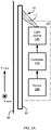
- FIG. 1 illustrates a typical application in which a user holds a handheld sensor device 10 against wall or other surface 12. The user moves device 10 transversely, as indicated by the arrows, to detect an object hidden from view behind the surface 12.
- the object may be hidden framing or a stud 14 defining a first edge 18, a centerline 20 and a second edge 22.
- Circuits within device 10 display the sensed information on display 16.
- a handheld detector unit typically indicates a sensed feature (e.g., an edge 18 or a centerline 20) using a visual display, such as display 16.
- a device's visual display may include one or more light-emitting diodes (LEDs) and/or liquid crystal display (LCD) in various configurations.
- LEDs light-emitting diodes
- LCD liquid crystal display
- some devices include an arrow-shaped LED display.
- Another device sold under the name Intellisensor ® made by Stanley in New England, Conn. uses a vertical line of LEDs for a display.
- U.S. Patent 6,249,113, issued June 19, 2001 and U.S. Patent 5,917,314, issued June 29, 1999 disclose several LCD and LED display configurations.
- a visual display 16 of a handheld sensor device is designed to assist the device user in determining some characteristic of a sensed object, such as an edge or a centerline.
- display 16 may indicate stud 14's edge 18, a centerline 20 located between edge 18 and edge 22, both edges 18 and 22, or other representations of stud 14.
- the display or displays 16 are typically mounted in the housing of the handheld sensor device. Thus, the display 16 is distance from the surface 12. That is, the display 16 is displaced both laterally and in depth from the surface 12 behind which the detected object is located. Furthermore, users often operate handheld detectors at skewed angles and in unusual positions such as when searching for objects that are behind ceilings, floors, corners, etc. For example, in FIG. 1 , if stud 14 is located behind a surface 12 that is close to a large visual obstruction, such as a water heater tank, the user will have difficulty seeing display 16. Even if display 16 is visible, the skewed viewing angle requires the user to make a visual angular estimate of the hidden object's location behind the surface, based on the display's position in the detector unit housing.
- a conventional handheld sensor device uses visual and audio feedback emanating from device to tell a user of the device that it has detected a stud or other hidden object.
- a handheld sensor device includes one or more LEDs and/or an LCD display to visually show the existence of a stud detected behind a wall or other surface.
- a single line or a plurality of lines and may be projected in one or more directions. Therefore, what is desired is a way to improve how information is presented to the user.
- a first aspect of the present invention provides for a handheld sensor device to project a visual indicator against a surface as claimed in claim 1.
- a second aspect of the present invention provides for a method to project a visual indicator against a surface using a handheld sensor device as claimed in claim 5.
- These quantities can take the form of electrical, magnetic, or radio signals capable of being stored, transferred, combined, compared, and otherwise manipulated in electronic circuitry or in a computer system. These signals may be referred to at times as bits, values, elements, symbols, characters, terms, numbers, or the like. Each step may be performed by hardware, software, firmware, or combinations thereof.
- Handheld sensor devices such as stud sensors, wall scanners, AC voltage detectors and magnetic field disturbance sensors, display information to a user using one or more LEDs and/or LCD displays located on the body of the device.
- Some devices use light passed through an aperture or slit on the body of the device to project a line or lines onto the wall surface.
- Such a slit does not produce a distinct two-dimensional icon but rather a length of light that has no discernable or distinctive features along a dimension. See, for example, United States Patent 6,259,241, by Krantz issued on July 10, 2001 and titled "Projected display for portable sensor indicating the location of a detected hidden object behind a surface", which discloses a handheld detector that projects a visible pattern onto the surface behind which a detected object is located.
- the projected pattern represents one or more predetermined characteristics of the detected object.
- a predetermined characteristic may include an edge, a position between two edges, a centerline between two edges, a characteristic of the object's mass, and/or an electromagnetic characteristic emitted or affected by the object.
- a narrow aperture defined in one end of the detector unit housing.
- the sensing circuit signals an activating circuit that energizes a light source within the detector housing. A portion of the light from the light source passes through the aperture and thereby projects a line onto the surface beneath which the detected object is located.
- the line is projected in a single dimension. That is, there is no lateral distinctiveness to the projected line.
- the projected line may not have distinct side edges or the line may easily be misaligned due to the LED being butted against the aperture opening.
- Embodiments of the present invention provide an improved optical light projection system able to project information through static or dynamic light patterns, such as icons, pixels, graphics and/or colors, to convey information to the user.
- Some embodiments include appropriate illuminators, apertures, and potentially lenses and computer-controlled apertures to create a dynamic information display projected onto the surface being scanned.
- Typical, handheld sensor devices provide information to the user using display(s) mounted on the body of the device, and not on the surface being scanned.
- Embodiments of the present invention instead display user-interface information directly onto the surface being scanned so as to more intimately convey detected information to the user.
- projected light does not introduce any physical interference
- a device that allows a user to super-impose marks (with pencil, tape, etc.) at precise locations on the wall as guided by the projected display improves the accuracy of such marks. These marks remain behind even after the unit is removed to aid the user in remembering where the hidden objects are located.
- Some embodiments of the present invention project graphical information and characters on the working area of a surface when using a handheld sensor devices (e.g. stud sensor), or other portable tool.
- the handheld sensor device includes light source(s), aperture(s), and optional lenses to project this graphical information against the surface.
- FIG. 1 illustrates a typical application in which a user holds a handheld sensor device against wall or other surface.
- the handheld sensor device is being used to scan the wall to determine the existence of hidden object beneath the surface.
- the handheld sensor device may project information various detected features. Such features may include whether the device is over an object (such as a stud), at an edge of the object, or at the center of the object, whether the object is metal, and whether the device is over electrically hot AC wires, etc.
- the device may display a direction to the hidden object.
- different colors may be projected to help convey changing information to the user. Embodiments project this information using one or more dynamic apertures.
- a static aperture is used to project an arrow icon or other fixed two-dimensional icon against a surface when a feature is detected by the device.
- the displayed icon is formed by LED light passing from a distance through a fixed-shaped aperture. Because the light is passed to the aperture from a distance (and not butted against the aperture), the projection is less susceptible to having indistinct side edges and misalignment.
- more complicated information may be projected and displayed via a dynamic aperture that changes during scanning to indicate the one or more detected features.
- the more complicated information may include one or more icons or other graphic as well as text.
- FIGS. 2A and 2B illustrate views of a handheld sensor device 10 in operation, in accordance with embodiments of the present invention.
- the handheld sensor device 10 is shown projecting a light stream 41 against a surface 30 resulting in a fixed two-dimensional icon 40 to reveal a feature of a hidden object, such as an edge 18 of a stud 14.
- the device 10 includes a sensor 100, a controller 110, and a light source 120.
- the sensor 100 senses the hidden object behind surface 30 and provides a data signal to the controller 110.
- the data signal may indicate the presence of an edge feature or a center feature of the hidden object.
- the sensor 100 may include one or more of a capacitive sensor, a stud sensor, an electrical field sensor, and a magnetic field sensor or the like.
- the controller 110 activates a light source 120 to project a light stream 41, which results a first icon 40 being displayed against the surface 30.
- the light source 120 includes a light emitting source 121 and an aperture 50 (shown in figures described below) when combined operate to shape the projected light from the light emitting source 121 through the aperture 50 as an arrow or other two-dimensional icon against the surface 30.
- the light source 120 may be formed with one or more LEDs (examples below), a lamp, bulb, or the like. In some embodiments, the light source 120 may also project a second icon against the surface 30. For example, in an example not forming part of the present invention, the first icon created from a first static aperture may represent a center feature and the second icon created from a second static aperture may represent an edge feature of the hidden object. In some embodiments, the light source 120 projects a single color icon, while in other embodiments, the light source 120 may project a selected one of two or more different colored icons to represent a corresponding two or more different features. For example, one color may be used to indicate an edge feature while another color is used to indicate a center feature.
- a first color may indicate a shallow stud while a second color indicates a deep stud.
- a red colored icon may be used to indicate an electrically hot AC circuit
- a blue icon may be used to represent a non-electrical metal object, such as a pipe
- a green icon may be used to represent a stud.
- FIG. 2B shows a top-down view outlining a handheld sensor device 10 projecting fixed two-dimensional icon (arrow 40) onto a surface 30, this example does not form part of the present invention.
- the device 10 is configured with a static aperture 50 that allows light to pass from the device 10.
- the aperture 50 is formed such that passing light projects the arrow 40.
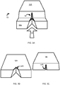
- FIGS. 3A, 3B and 3C show perspective views of a housing and a projected arrow, in accordance with embodiments of the present invention.
- the housing of the handheld sensor device 10 includes a base housing 10A ( FIG. 3B ) and top housing 10B ( FIG. 3C ) and is shown combined into a single integrated housing ( FIG. 3A ).
- the base housing 10A includes a notch 50A, which appears as a wide-angled inverted 'V' positioned parallel to the surface 30.
- the plane of the wide-angled inverted 'V' may be exactly parallel (0 degress) or off-parallel (up to 30 degrees or more from parallel) to the surface 30.
- the top housing 10B also includes a notched 50B, but appears as a narrow-angled inverted 'V' positioned perpendicular to the surface 30. Again, the plane of the narrow-angled inverted 'V' may be exactly perpendicular (0 degress) or off- perpendicular (up to 30 degrees or more from perpendicular) to the surface 30.
- the two notches 50A and 50B define a static aperture 50. Due to the inverted 'V' shapes from notches 50A and 50B positioned together, when the two housing sections 10A and 10B are combined the light passing from inside the device 10 through the defined aperture 50 results in an arrow 40 projected on the surface 30. This example with the static aperture does not form part of the present invention.
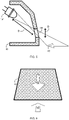
- FIGS. 4 , 5 , 6 , 7A and 7B shows a relationship between an LED, an aperture and a projected arrow, in accordance with embodiments of the present invention.
- the light source projects an arrow 40 in front of the device.
- the arrow 40 has a distinctive two-dimensional shape unlike a one-dimensional line of conventional devices.
- the LED butts up against the housing wall such that the greatest dimension of the aperture is greater than the distance between the LED and the housing wall.
- Embodiments of the present invention disclose a light emitting source (e.g., LED 121) distant from the aperture 50. Distancing the LED 121 from the aperture enables the handheld sensor device 10 to define a distinct and fixed two-dimensional icon (e.g., arrow 40) against the surface 30.
- an LED 121 is used as the light emitting source.
- the LED 121 is positioned distant from the aperture 50.
- the greatest perpendicular dimension of the aperture 50 defines a distance D 1 .
- D 1 the distance between the aperture 50.
- the LED 121 is positioned internally within the device10 at a distance D 2 from the aperture 50, where D 2 is greater than D 1 (D 2 > D 1 ).
- the ratio D 2 :D 2 is approximately 3:1, 4:1, 5:1, or greater than 5:1.
- the greatest dimension of the aperture (Di) may be 2 mm and the distance (D 2 ) between the aperture and the LED may be 9 mm, such that the ratio D 2 :D 1 is be 4.5:1.
- FIG. 6 shows a view up into the aperture 50 from a perspective near the surface 30 and near the projected arrow 40. From this perspective, the aperture 50 appears more as an arrow.
- the handheld sensor device 10 is shown with a base housing 10A and a top housing 10B.
- the base housing 10A has a wide V-shaped notch 50A oriented perpendicularly or nearly perpendicular to the surface 30.
- the top housing 10B defines a trapezoid notch 50B with a narrow top edge parallel to both the surface and to an imaginary similar-length or wider bottom line and also defines two side edges parallel or nearly parallel to one another.
- the distance D 2 between the aperture 50 and the light emitting source 121 is approximately 2 to 5 (or 5 to 30 or more) times farther than the distance D 1 of the aperture.
- the ratio D 2 :D 1 is shown to be approximately 20:1. Channeling the light from the light emitting source 121 to the aperture 50 allows for this ratio to be larger and more efficient.
- FIG. 8 shows method of projecting a visual indicator, in accordance with embodiments of the present invention.
- the method using a handheld sensor device 10, begins at block 200 by sensing an object 14 behind a surface 30.
- the device 10 determines a first feature of the sensed object 14.
- the device 10 projects, through an aperture 50 shaped to project light as an arrow 40 or other distinct two-dimensional icon onto the surface 30, a first icon indicating the first feature.
- the device 10 determines a second feature of the sensed object exists behind the surface 30.
- the device projects, through an aperture 50, a second icon indicating the second feature.
- the aperture of steps 220 and 240 are a common dynamic aperture.
- the object 14 may be a stud and the first feature may be an edge 18 or 22 of the stud, and the second feature may be a centerline 20 of the stud 14.
- the first and second projected icons may be identical, have different colors and/or different shapes or orientations.
- the device detects absence of the feature and disable projection.
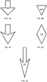
- FIGS. 9A, 9B, 9C, 9D and 9E show various projected arrows, in accordance with embodiments of the present invention.
- Each arrow comprises a distinct two-dimensional icon, is formed by passing light at a distance D 2 from an aperture 50, and includes a distinctive head and may also include a tail or shaft.
- FIG. 9A shows a traditional arrowhead and shaft 40A with a straight-lined head backing.
- FIG. 9B the arrowhead 40B similar to the arrow 40A but is void of a shaft.
- the arrowhead and shaft 40C includes an arrowhead with V-lined head backing.
- the arrowhead 40D is double-headed.
- the arrowhead and shaft 40E is elongated. Unlike a projected line, each arrow has characteristics in two dimensions and is used to distinctly point to a location on a surface 30.
- a handheld sensor device 10 may include a plurality of passive apertures 50 each channeling light from a separate LED or other light source. Each aperture may be shaped and position to form a separate icon.
- a first aperture 50 may be formed to present an arrow 40A. To project the arrow from the first aperture 50, a first LED may be illuminated.
- a second aperture 50 may be formed to present an arrow pointing to the left indicating an object is to the left of the device 10.
- a second LED may be illuminated channeling light just to the second aperture 50.
- a third aperture 50 may be formed to present an arrow pointing to the right to indicate an object is to the right of the device 10.
- a third LED may be illuminated channeling light just to the third aperture 50.
- Separate channels may be formed with individual clear material, such as plastic tubes, or may be formed by physically dividing an open space with the device 10.
- the aperture 50 is dynamic. That is, light passing through the aperture is actively regulated such that a variety of icons or other information may be projected onto the surface 30. Light may be regulated through an LCD lens, through an active shutter, or the like. Examples of devices 10 using a dynamic aperture 50 are given below.
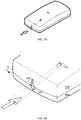
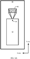
- FIGS. 10A , 10B , 10C , 10D and 11 show top-down views of a handheld sensor device 10 projecting display information, in accordance with embodiments of the present invention.
- a handheld sensor device 10 includes a dynamic aperture 50, which allows light to pass to form a display area 40 on the surface 30.
- the device 10 projects one or more distinct two-dimensional icon within this display area 40. Several of possible icons are described below by way of example.
- a user operates a handheld sensor device 10 searching for a hidden stud 14.
- the device 10 detects an edge 18 to the left of the sensor but it not yet over the edge 18.
- Conventional devices provide an indication showing a hidden stud is close but does not indicate which direction the user should move the device.
- the device 10 may determine a direction of the hidden object.
- the handheld sensor device 10 projects an arrow 40F indicating to the user that the hidden object is to the left. Simultaneously, the device 10 may provide similar information on a display 16.
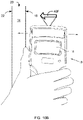
- the user has moved the device 10 over an edge 18 of the stud 14.
- the device 10 projects an icon to the surface 30.
- the device 10 projects both the letter "EDGE" and an arrow 40G.
- the icon is projected at a fixed location relative to the device 10.
- the icon may appear stationary relative to the surface 30 but moves relative to the device 10 while the user moves the device 10 to the left and right over the edge.
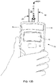
- the handheld sensor device 10 is nearly centered over the stud.
- the device 10 projects a center icon "CNTR" with an arrow 40H to indicate the device 10 is over a center feature of the stud 14.
- the device 10 may track the relative position of the feature and adjust its projected icon to appear stationary on the surface as the user moves the device about the centerline of the stud 14.
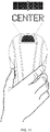
- the device 10 projects to the surface 30 the word "CENTER” along with a bar.
- the bar represents the hidden stud 14 and the word "CENTER” represents that the device 10 is centered over the stud 14.
- Other projections are possible with a handheld sensor device 10 that has a dynamic aperture.
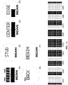
- FIGS. 12A, 12B, 12C, 12D and 13 show various display information, in accordance with embodiments of the present invention.
- FIG. 12A shows a display area 40 that indicates the device 10 is near an edge of the stud 14.
- FIG. 12B the user has moved the device to the left such that it is centered over an edge as indicated by the word "EDGE", by the left-pointing arrow and by the shadowed area to the left side of the display area 40.
- FIG. 12C the user has centered the device 10 directly above the centerline of the stud 14.
- the projected display area 40 shows a shadowed area representing the hidden stud and also the word "CNTR" or "CENTER” to highlight to the user that the device 10 is centered over the stud 14.
- FIG. 12D shows the device 10 moved to the left so that it is centered over another edge.
- the display 40 shows approximately a mirrored images to that shown in FIG. 12B .
- the shadowed area may be animated such that is appears relatively stationary against the surface 30 to simulate a view of the stud 14 looking through the surface 30.
- the pixilated characters making up the words "CENTER”, "CNTR” or “EDGE” are examples of dynamic text that the handheld sensor device 10 projects depending on the circumstances and context of use for the device 10 at that instant in time.
- the content and specifics of the displayed information is determined by a computer, microprocessor or micro controller controlling the device 10.
- the displayed information also depends on what the device 10 is sensing.
- Each icon described above e.g., arrows shown in FIGS. 12B and 12D
- convey information e.g., directional information
- Each icon may be static or dynamical and is turned on or off by the device 10.
- the projected information depends on what information the handheld sensor device 10 has measured and needs to display to the user. It may include characters, graphics, and icons in various colors to convey user-interface information to the user of the device 10. Some embodiments display the projected information via an LCD aperture or other dynamic aperture within the device 10.
- the LCD aperture may be a transmissive, negative type, in which the pixels that are transparent will be projected. All other pixels are non-transparent, thus block the light.
- the displayed icon may be colored by being projected: (1) from a colored LED, (2) through a colored lens (e.g., at or near the aperture), or (3) through a colored LCD.
- graphics on the LCD object are pre-distorted (to compensate for tilt and projection angles), and passed through appropriate lenses, so that they appear not to be distorted and correct when projected to the surface.
- the image on the LCD object is distorted such that the projection on the surface 30 is not distorted.
- Control of the information being displayed is managed by the microcontroller or the like, which updates and changes the information dynamically and in real time depending on the current sensor measurements and operating mode.
- FIG. 13 shows additional possible displayed information.
- Icon (A) shows a projection of an example initialization information.
- Icon (B) shows a projection of information telling a user that the device 10 is in a stud scan mode.
- Icon (C) shows a projection of information telling a user that the detector 10 found a center of a stud 14 (similar to FIGS. 10C , 11 and 12C ).
- Icon (D) shows a projection of information telling a user that the detector 10 found an edge of a stud 14 (similar to FIG. 10B ).
- Icon (E) shows a projection of information telling a user that the detector 10 move back towards a stud 14 (similar to FIG. 10A ).
- Icon (F) shows a projection of instructions to a user to begin scanning.
- Icons (G1) through (G9) show a progression of projections as a device 10 passes over a stud 14 (shown with black pixels) from right to left.
- FIG. 14 shows a dynamic light source 120, in accordance with embodiments of the present invention.
- the light source 120 also referred to as a display projection system, includes
- a light emitting source 121 such as an LED, which projects light along a projection path 300.
- a condensing lens 310 focuses this light into a dynamic aperture 50, such an LCD panel.
- the dynamic aperture 50 is solid black or opaque, light does not pass through.
- the dynamic aperture 50 displays a negative of an image to project. That is, the dynamic aperture 50 is non-transparent for areas not representing the icon to be displayed. Light passing through the dynamic aperture 50 is filtered by this negative image. The light then passes a projection lens 320 and a prism 330. From the prism 330, the projected light 41 provides a visual indication against the surface 30 as icon 40.
- the LCD panel may contain color LCDs thereby allowing colored icons and text.
- the LCD panel may allow for partially translucent pixels thus allowing grayscale icons and text.
Landscapes
- Physics & Mathematics (AREA)
- Life Sciences & Earth Sciences (AREA)
- General Physics & Mathematics (AREA)
- General Life Sciences & Earth Sciences (AREA)
- Remote Sensing (AREA)
- Geology (AREA)
- Environmental & Geological Engineering (AREA)
- Engineering & Computer Science (AREA)
- Geophysics (AREA)
- Electromagnetism (AREA)
- Position Input By Displaying (AREA)
- Devices For Indicating Variable Information By Combining Individual Elements (AREA)
- User Interface Of Digital Computer (AREA)
- Alarm Systems (AREA)
Applications Claiming Priority (3)
| Application Number | Priority Date | Filing Date | Title |
|---|---|---|---|
| US10585608P | 2008-10-16 | 2008-10-16 | |
| US12/580,894 US8581724B2 (en) | 2008-10-16 | 2009-10-16 | Dynamic information projection for a wall sensor |
| PCT/US2009/061061 WO2010045592A1 (en) | 2008-10-16 | 2009-10-16 | Dynamic information projection for a wall sensor |
Publications (3)
| Publication Number | Publication Date |
|---|---|
| EP2350993A1 EP2350993A1 (en) | 2011-08-03 |
| EP2350993A4 EP2350993A4 (en) | 2017-06-14 |
| EP2350993B1 true EP2350993B1 (en) | 2022-04-13 |
Family
ID=42106930
Family Applications (1)
| Application Number | Title | Priority Date | Filing Date |
|---|---|---|---|
| EP09821346.5A Active EP2350993B1 (en) | 2008-10-16 | 2009-10-16 | Dynamic information projection for a wall sensor |
Country Status (6)
| Country | Link |
|---|---|
| US (2) | US8581724B2 (zh) |
| EP (1) | EP2350993B1 (zh) |
| JP (1) | JP5646496B2 (zh) |
| CN (1) | CN102187372B (zh) |
| CA (1) | CA2739891C (zh) |
| WO (1) | WO2010045592A1 (zh) |
Families Citing this family (19)
| Publication number | Priority date | Publication date | Assignee | Title |
|---|---|---|---|---|
| US8731333B2 (en) | 2010-04-06 | 2014-05-20 | Jeffrey M. Sieracki | Inspection of hidden structure |
| US8760145B2 (en) * | 2011-07-08 | 2014-06-24 | John Charles Tutton | Electronic device for detecting an object beneath a wall section of interest having a persistent image display |
| WO2015013280A1 (en) | 2013-07-22 | 2015-01-29 | Google Inc. | Method, system, and medium for projecting light to indicate a device status |
| US9508244B2 (en) * | 2014-03-07 | 2016-11-29 | Zircon Corporation | Sensor with a radiant indicator |
| EP3161414B1 (de) | 2014-06-25 | 2021-01-20 | Robert Bosch GmbH | Ortungssystem mit handgeführter ortungseinheit |
| EP3433849B1 (en) | 2016-03-23 | 2023-11-08 | Koninklijke Philips N.V. | Systems and methods for projecting multiple images on a common area of an outer surface of a housing |
| US10908312B2 (en) | 2016-06-24 | 2021-02-02 | Stanley Black & Decker Inc. | Systems and methods for locating a metal object |
| US10484742B2 (en) | 2016-07-26 | 2019-11-19 | Umbo, Inc. | Method and system for providing information to a user via a projection device |
| US10140821B2 (en) * | 2017-02-03 | 2018-11-27 | Vivint, Inc. | Thermostat with downcast light |
| USD860994S1 (en) * | 2018-01-10 | 2019-09-24 | Zircon Corporation | Handheld scanner |
| USD860995S1 (en) * | 2018-01-10 | 2019-09-24 | Zircon Corporation | Handheld scanner |
| JP2020134489A (ja) * | 2019-02-26 | 2020-08-31 | 株式会社マキタ | 埋設物探査装置 |
| DE102020104789A1 (de) | 2019-02-26 | 2020-08-27 | Makita Corporation | Suchvorrichtung für ein eingebettetes objekt |
| CN113534281A (zh) * | 2020-04-14 | 2021-10-22 | 深圳市博利凌科技有限公司 | 用于感测物体表面之后隐藏物位置的扫描仪及方法 |
| USD950555S1 (en) * | 2020-11-12 | 2022-05-03 | Zircon Corporation | Scanner |
| USD950556S1 (en) * | 2020-11-12 | 2022-05-03 | Zircon Corporation | Scanner |
| USD950554S1 (en) * | 2020-11-12 | 2022-05-03 | Zircon Corporation | Scanner |
| US11686875B2 (en) * | 2020-12-11 | 2023-06-27 | Robert Bosch Tool Corporation | Stud finder employing photochromism |
| US11257257B1 (en) * | 2021-03-13 | 2022-02-22 | Michael H. Panosian | Multi-mode obscured object detector |
Family Cites Families (32)
| Publication number | Priority date | Publication date | Assignee | Title |
|---|---|---|---|---|
| US4099118A (en) * | 1977-07-25 | 1978-07-04 | Franklin Robert C | Electronic wall stud sensor |
| US4464622A (en) * | 1982-03-11 | 1984-08-07 | Franklin Robert C | Electronic wall stud sensor |
| JP2681040B2 (ja) * | 1987-03-16 | 1997-11-19 | 株式会社マイゾックス | 非金属・金属部材探知器 |
| US5143442A (en) * | 1991-05-07 | 1992-09-01 | Tamapack Co., Ltd. | Portable projection device |
| US5620363A (en) * | 1992-01-24 | 1997-04-15 | Turner Intellectual Property Limited | Powered grinding tool |
| US5457394A (en) * | 1993-04-12 | 1995-10-10 | The Regents Of The University Of California | Impulse radar studfinder |
| US5917314A (en) * | 1996-08-08 | 1999-06-29 | Zircon Corporation | Electronic wall-stud sensor with three capacitive elements |
| KR100220888B1 (ko) * | 1997-01-18 | 1999-09-15 | 박호군 | 이동 개구를 이용한 다시야 3차원 영상 구현 방법 및 시스템 |
| US6249113B1 (en) * | 1998-08-14 | 2001-06-19 | Zircon Corporation | Hand held sensor and display |
| US6266048B1 (en) * | 1998-08-27 | 2001-07-24 | Hewlett-Packard Company | Method and apparatus for a virtual display/keyboard for a PDA |
| JP2000112021A (ja) * | 1998-10-01 | 2000-04-21 | Canon Inc | 投写型表示装置 |
| JP2000275573A (ja) * | 1999-03-29 | 2000-10-06 | Miyota Kk | レーザーポインター |
| US6259241B1 (en) * | 1999-06-22 | 2001-07-10 | Zircon Corporation | Projected display for portable sensor indicating the location of a detected hidden object behind a surface |
| JP2002251256A (ja) * | 2001-02-23 | 2002-09-06 | Hitachi Cable Ltd | 液晶プロジェクタプレゼンテーション用指し棒及びこれを用いたプレゼンテーションシステム並びにポインタの表示方法 |
| CA2359599A1 (en) * | 2001-10-22 | 2003-04-22 | Kyle J. Doerksen | Positioning system for ground penetrating radar instruments |
| US20030218469A1 (en) * | 2002-02-27 | 2003-11-27 | Brazell Kenneth M. | Multifunctional object sensor |
| US6894508B2 (en) * | 2002-06-28 | 2005-05-17 | Solar Wide Industrial Ltd. | Apparatus and method for locating objects behind a wall lining |
| US7495455B2 (en) * | 2002-06-28 | 2009-02-24 | Solar Wide Industrial Limited | Stud sensing device |
| US7256587B2 (en) * | 2002-06-28 | 2007-08-14 | Solar Wide Industrial Limited | Multiple sensitivity stud sensing device |
| JP2004037317A (ja) * | 2002-07-04 | 2004-02-05 | Murata Mfg Co Ltd | 三次元形状測定方法、三次元形状測定装置 |
| JP2004184286A (ja) * | 2002-12-04 | 2004-07-02 | Matsushita Electric Works Ltd | 背後部材検知装置 |
| TW594549B (en) * | 2002-12-31 | 2004-06-21 | Ind Tech Res Inst | Device and method for generating virtual keyboard/display |
| US7336078B1 (en) * | 2003-10-04 | 2008-02-26 | Seektech, Inc. | Multi-sensor mapping omnidirectional sonde and line locators |
| US7237341B2 (en) * | 2003-10-10 | 2007-07-03 | The Stanley Works | Studfinder and laser line layout tool |
| US7116091B2 (en) * | 2004-03-04 | 2006-10-03 | Zircon Corporation | Ratiometric stud sensing |
| DE102004011285A1 (de) * | 2004-03-09 | 2005-09-29 | Robert Bosch Gmbh | Ortungsgerät |
| US20050219240A1 (en) * | 2004-04-05 | 2005-10-06 | Vesely Michael A | Horizontal perspective hands-on simulator |
| US7193405B2 (en) * | 2004-06-07 | 2007-03-20 | The Stanley Works | Electronic multi-depth object locator with self-illuminating optical element warning and detection |
| CN2872361Y (zh) * | 2006-02-28 | 2007-02-21 | 南京德朔实业有限公司 | 物体探测器 |
| CN100514183C (zh) * | 2006-05-29 | 2009-07-15 | 晶荧光学科技有限公司 | 便携式电子设备 |
| JP5141041B2 (ja) * | 2007-02-23 | 2013-02-13 | 株式会社ニコン | 投影システムおよびプロジェクタ |
| US7504817B2 (en) * | 2007-03-28 | 2009-03-17 | Solar Wide Industrial Limited | Stud sensor |
-
2009
- 2009-10-16 CN CN200980141131.9A patent/CN102187372B/zh active Active
- 2009-10-16 US US12/580,894 patent/US8581724B2/en active Active
- 2009-10-16 JP JP2011532296A patent/JP5646496B2/ja active Active
- 2009-10-16 CA CA2739891A patent/CA2739891C/en active Active
- 2009-10-16 EP EP09821346.5A patent/EP2350993B1/en active Active
- 2009-10-16 WO PCT/US2009/061061 patent/WO2010045592A1/en active Application Filing
-
2013
- 2013-11-11 US US14/076,972 patent/US9589431B2/en active Active
Also Published As
| Publication number | Publication date |
|---|---|
| US20140139348A1 (en) | 2014-05-22 |
| CA2739891A1 (en) | 2010-04-22 |
| CN102187372B (zh) | 2014-04-30 |
| WO2010045592A1 (en) | 2010-04-22 |
| EP2350993A4 (en) | 2017-06-14 |
| JP2012506055A (ja) | 2012-03-08 |
| US8581724B2 (en) | 2013-11-12 |
| US20100097212A1 (en) | 2010-04-22 |
| US9589431B2 (en) | 2017-03-07 |
| CA2739891C (en) | 2017-03-28 |
| CN102187372A (zh) | 2011-09-14 |
| JP5646496B2 (ja) | 2014-12-24 |
| EP2350993A1 (en) | 2011-08-03 |
Similar Documents
| Publication | Publication Date | Title |
|---|---|---|
| EP2350993B1 (en) | Dynamic information projection for a wall sensor | |
| US8854279B2 (en) | Position detecting system and position detecting program | |
| JPH0720761Y2 (ja) | 位置決定装置 | |
| US20110035952A1 (en) | Display of results of a measurement of workpieces as a function of the detection of the gesture of a user | |
| US20020163505A1 (en) | Coordinate input/detection device detecting installation position of light-receiving device used for detecting coordinates | |
| KR20100007673A (ko) | 감지시스템 | |
| US8899474B2 (en) | Interactive document reader | |
| CN104238831A (zh) | 利用反射光的光学触摸屏幕系统 | |
| JP2010503910A (ja) | 対象の方向性の決定 | |
| JP2008516352A (ja) | 強化現実システムにおける照明シミュレーションおよび影シミュレーションのための装置および方法 | |
| US20130010287A1 (en) | Electronic device for detecting an object beneath a wall section of interest having a persistent image display | |
| US20120293555A1 (en) | Information-processing device, method thereof and display device | |
| KR20160126077A (ko) | 제스처 감지 중에 입력 수단의 3d 위치를 시그널링하기 위한 사용자 인터페이스 및 방법 | |
| EP3032375B1 (en) | Input operation system | |
| EP3336579A1 (en) | Optical sensor-based position sensing of a radio frequency imaging device | |
| KR100686718B1 (ko) | 디스플레이장치 및 이를 구비한 휴대용 컴퓨터 | |
| JP2010146573A (ja) | サイズ可変型センサーシステムとセンシング区域のサイズの再定義方法 | |
| EP2857934A1 (en) | Method and apparatus for determining the pose of a light source using an optical sensing array | |
| KR20130120708A (ko) | 다중 디스플레이 패널을 사용하는 디스플레이 장치 및 방법 | |
| JP5466609B2 (ja) | 光学式位置検出装置及び再帰性反射板ユニット | |
| JP5929125B2 (ja) | センサ装置 | |
| CN110307822A (zh) | 距离侦测装置 | |
| JP2023531302A (ja) | 動的な形状スケッチングのためのシステム及び方法 | |
| JP2010102378A (ja) | 入力制御装置及び入力制御方法 | |
| EP4336323A1 (en) | Device orientation detection |
Legal Events
| Date | Code | Title | Description |
|---|---|---|---|
| PUAI | Public reference made under article 153(3) epc to a published international application that has entered the european phase |
Free format text: ORIGINAL CODE: 0009012 |
|
| 17P | Request for examination filed |
Effective date: 20110516 |
|
| AK | Designated contracting states |
Kind code of ref document: A1 Designated state(s): AT BE BG CH CY CZ DE DK EE ES FI FR GB GR HR HU IE IS IT LI LT LU LV MC MK MT NL NO PL PT RO SE SI SK SM TR |
|
| DAX | Request for extension of the european patent (deleted) | ||
| REG | Reference to a national code |
Ref country code: DE Ref legal event code: R079 Ref document number: 602009064394 Country of ref document: DE Free format text: PREVIOUS MAIN CLASS: G08B0025000000 Ipc: G01V0003150000 |
|
| RA4 | Supplementary search report drawn up and despatched (corrected) |
Effective date: 20170512 |
|
| RIC1 | Information provided on ipc code assigned before grant |
Ipc: G01V 3/15 20060101AFI20170508BHEP |
|
| STAA | Information on the status of an ep patent application or granted ep patent |
Free format text: STATUS: EXAMINATION IS IN PROGRESS |
|
| 17Q | First examination report despatched |
Effective date: 20181120 |
|
| STAA | Information on the status of an ep patent application or granted ep patent |
Free format text: STATUS: EXAMINATION IS IN PROGRESS |
|
| GRAP | Despatch of communication of intention to grant a patent |
Free format text: ORIGINAL CODE: EPIDOSNIGR1 |
|
| STAA | Information on the status of an ep patent application or granted ep patent |
Free format text: STATUS: GRANT OF PATENT IS INTENDED |
|
| INTG | Intention to grant announced |
Effective date: 20211108 |
|
| GRAS | Grant fee paid |
Free format text: ORIGINAL CODE: EPIDOSNIGR3 |
|
| GRAA | (expected) grant |
Free format text: ORIGINAL CODE: 0009210 |
|
| STAA | Information on the status of an ep patent application or granted ep patent |
Free format text: STATUS: THE PATENT HAS BEEN GRANTED |
|
| AK | Designated contracting states |
Kind code of ref document: B1 Designated state(s): AT BE BG CH CY CZ DE DK EE ES FI FR GB GR HR HU IE IS IT LI LT LU LV MC MK MT NL NO PL PT RO SE SI SK SM TR |
|
| REG | Reference to a national code |
Ref country code: GB Ref legal event code: FG4D |
|
| REG | Reference to a national code |
Ref country code: CH Ref legal event code: EP |
|
| REG | Reference to a national code |
Ref country code: DE Ref legal event code: R096 Ref document number: 602009064394 Country of ref document: DE |
|
| REG | Reference to a national code |
Ref country code: IE Ref legal event code: FG4D |
|
| REG | Reference to a national code |
Ref country code: AT Ref legal event code: REF Ref document number: 1483822 Country of ref document: AT Kind code of ref document: T Effective date: 20220515 |
|
| REG | Reference to a national code |
Ref country code: LT Ref legal event code: MG9D |
|
| REG | Reference to a national code |
Ref country code: NL Ref legal event code: MP Effective date: 20220413 |
|
| REG | Reference to a national code |
Ref country code: AT Ref legal event code: MK05 Ref document number: 1483822 Country of ref document: AT Kind code of ref document: T Effective date: 20220413 |
|
| PG25 | Lapsed in a contracting state [announced via postgrant information from national office to epo] |
Ref country code: NL Free format text: LAPSE BECAUSE OF FAILURE TO SUBMIT A TRANSLATION OF THE DESCRIPTION OR TO PAY THE FEE WITHIN THE PRESCRIBED TIME-LIMIT Effective date: 20220413 |
|
| PG25 | Lapsed in a contracting state [announced via postgrant information from national office to epo] |
Ref country code: SE Free format text: LAPSE BECAUSE OF FAILURE TO SUBMIT A TRANSLATION OF THE DESCRIPTION OR TO PAY THE FEE WITHIN THE PRESCRIBED TIME-LIMIT Effective date: 20220413 Ref country code: PT Free format text: LAPSE BECAUSE OF FAILURE TO SUBMIT A TRANSLATION OF THE DESCRIPTION OR TO PAY THE FEE WITHIN THE PRESCRIBED TIME-LIMIT Effective date: 20220816 Ref country code: NO Free format text: LAPSE BECAUSE OF FAILURE TO SUBMIT A TRANSLATION OF THE DESCRIPTION OR TO PAY THE FEE WITHIN THE PRESCRIBED TIME-LIMIT Effective date: 20220713 Ref country code: LT Free format text: LAPSE BECAUSE OF FAILURE TO SUBMIT A TRANSLATION OF THE DESCRIPTION OR TO PAY THE FEE WITHIN THE PRESCRIBED TIME-LIMIT Effective date: 20220413 Ref country code: HR Free format text: LAPSE BECAUSE OF FAILURE TO SUBMIT A TRANSLATION OF THE DESCRIPTION OR TO PAY THE FEE WITHIN THE PRESCRIBED TIME-LIMIT Effective date: 20220413 Ref country code: GR Free format text: LAPSE BECAUSE OF FAILURE TO SUBMIT A TRANSLATION OF THE DESCRIPTION OR TO PAY THE FEE WITHIN THE PRESCRIBED TIME-LIMIT Effective date: 20220714 Ref country code: FI Free format text: LAPSE BECAUSE OF FAILURE TO SUBMIT A TRANSLATION OF THE DESCRIPTION OR TO PAY THE FEE WITHIN THE PRESCRIBED TIME-LIMIT Effective date: 20220413 Ref country code: ES Free format text: LAPSE BECAUSE OF FAILURE TO SUBMIT A TRANSLATION OF THE DESCRIPTION OR TO PAY THE FEE WITHIN THE PRESCRIBED TIME-LIMIT Effective date: 20220413 Ref country code: BG Free format text: LAPSE BECAUSE OF FAILURE TO SUBMIT A TRANSLATION OF THE DESCRIPTION OR TO PAY THE FEE WITHIN THE PRESCRIBED TIME-LIMIT Effective date: 20220713 Ref country code: AT Free format text: LAPSE BECAUSE OF FAILURE TO SUBMIT A TRANSLATION OF THE DESCRIPTION OR TO PAY THE FEE WITHIN THE PRESCRIBED TIME-LIMIT Effective date: 20220413 |
|
| PG25 | Lapsed in a contracting state [announced via postgrant information from national office to epo] |
Ref country code: PL Free format text: LAPSE BECAUSE OF FAILURE TO SUBMIT A TRANSLATION OF THE DESCRIPTION OR TO PAY THE FEE WITHIN THE PRESCRIBED TIME-LIMIT Effective date: 20220413 Ref country code: LV Free format text: LAPSE BECAUSE OF FAILURE TO SUBMIT A TRANSLATION OF THE DESCRIPTION OR TO PAY THE FEE WITHIN THE PRESCRIBED TIME-LIMIT Effective date: 20220413 Ref country code: IS Free format text: LAPSE BECAUSE OF FAILURE TO SUBMIT A TRANSLATION OF THE DESCRIPTION OR TO PAY THE FEE WITHIN THE PRESCRIBED TIME-LIMIT Effective date: 20220813 |
|
| REG | Reference to a national code |
Ref country code: DE Ref legal event code: R097 Ref document number: 602009064394 Country of ref document: DE |
|
| PG25 | Lapsed in a contracting state [announced via postgrant information from national office to epo] |
Ref country code: SM Free format text: LAPSE BECAUSE OF FAILURE TO SUBMIT A TRANSLATION OF THE DESCRIPTION OR TO PAY THE FEE WITHIN THE PRESCRIBED TIME-LIMIT Effective date: 20220413 Ref country code: SK Free format text: LAPSE BECAUSE OF FAILURE TO SUBMIT A TRANSLATION OF THE DESCRIPTION OR TO PAY THE FEE WITHIN THE PRESCRIBED TIME-LIMIT Effective date: 20220413 Ref country code: RO Free format text: LAPSE BECAUSE OF FAILURE TO SUBMIT A TRANSLATION OF THE DESCRIPTION OR TO PAY THE FEE WITHIN THE PRESCRIBED TIME-LIMIT Effective date: 20220413 Ref country code: EE Free format text: LAPSE BECAUSE OF FAILURE TO SUBMIT A TRANSLATION OF THE DESCRIPTION OR TO PAY THE FEE WITHIN THE PRESCRIBED TIME-LIMIT Effective date: 20220413 Ref country code: DK Free format text: LAPSE BECAUSE OF FAILURE TO SUBMIT A TRANSLATION OF THE DESCRIPTION OR TO PAY THE FEE WITHIN THE PRESCRIBED TIME-LIMIT Effective date: 20220413 Ref country code: CZ Free format text: LAPSE BECAUSE OF FAILURE TO SUBMIT A TRANSLATION OF THE DESCRIPTION OR TO PAY THE FEE WITHIN THE PRESCRIBED TIME-LIMIT Effective date: 20220413 |
|
| PLBE | No opposition filed within time limit |
Free format text: ORIGINAL CODE: 0009261 |
|
| STAA | Information on the status of an ep patent application or granted ep patent |
Free format text: STATUS: NO OPPOSITION FILED WITHIN TIME LIMIT |
|
| 26N | No opposition filed |
Effective date: 20230116 |
|
| PG25 | Lapsed in a contracting state [announced via postgrant information from national office to epo] |
Ref country code: SI Free format text: LAPSE BECAUSE OF FAILURE TO SUBMIT A TRANSLATION OF THE DESCRIPTION OR TO PAY THE FEE WITHIN THE PRESCRIBED TIME-LIMIT Effective date: 20220413 Ref country code: MC Free format text: LAPSE BECAUSE OF FAILURE TO SUBMIT A TRANSLATION OF THE DESCRIPTION OR TO PAY THE FEE WITHIN THE PRESCRIBED TIME-LIMIT Effective date: 20220413 |
|
| REG | Reference to a national code |
Ref country code: CH Ref legal event code: PL |
|
| REG | Reference to a national code |
Ref country code: BE Ref legal event code: MM Effective date: 20221031 |
|
| PG25 | Lapsed in a contracting state [announced via postgrant information from national office to epo] |
Ref country code: LU Free format text: LAPSE BECAUSE OF NON-PAYMENT OF DUE FEES Effective date: 20221016 |
|
| P01 | Opt-out of the competence of the unified patent court (upc) registered |
Effective date: 20230526 |
|
| PG25 | Lapsed in a contracting state [announced via postgrant information from national office to epo] |
Ref country code: LI Free format text: LAPSE BECAUSE OF NON-PAYMENT OF DUE FEES Effective date: 20221031 Ref country code: CH Free format text: LAPSE BECAUSE OF NON-PAYMENT OF DUE FEES Effective date: 20221031 |
|
| PG25 | Lapsed in a contracting state [announced via postgrant information from national office to epo] |
Ref country code: BE Free format text: LAPSE BECAUSE OF NON-PAYMENT OF DUE FEES Effective date: 20221031 |
|
| PG25 | Lapsed in a contracting state [announced via postgrant information from national office to epo] |
Ref country code: IE Free format text: LAPSE BECAUSE OF NON-PAYMENT OF DUE FEES Effective date: 20221016 |
|
| PGFP | Annual fee paid to national office [announced via postgrant information from national office to epo] |
Ref country code: GB Payment date: 20231027 Year of fee payment: 15 |
|
| PG25 | Lapsed in a contracting state [announced via postgrant information from national office to epo] |
Ref country code: IT Free format text: LAPSE BECAUSE OF FAILURE TO SUBMIT A TRANSLATION OF THE DESCRIPTION OR TO PAY THE FEE WITHIN THE PRESCRIBED TIME-LIMIT Effective date: 20220413 |
|
| PGFP | Annual fee paid to national office [announced via postgrant information from national office to epo] |
Ref country code: FR Payment date: 20231025 Year of fee payment: 15 Ref country code: DE Payment date: 20231027 Year of fee payment: 15 |
|
| PG25 | Lapsed in a contracting state [announced via postgrant information from national office to epo] |
Ref country code: HU Free format text: LAPSE BECAUSE OF FAILURE TO SUBMIT A TRANSLATION OF THE DESCRIPTION OR TO PAY THE FEE WITHIN THE PRESCRIBED TIME-LIMIT; INVALID AB INITIO Effective date: 20091016 |
|
| PG25 | Lapsed in a contracting state [announced via postgrant information from national office to epo] |
Ref country code: CY Free format text: LAPSE BECAUSE OF FAILURE TO SUBMIT A TRANSLATION OF THE DESCRIPTION OR TO PAY THE FEE WITHIN THE PRESCRIBED TIME-LIMIT Effective date: 20220413 |