EP2346471B1 - Verfahren und vorrichtung für abwechselndes sieben und mischen von pulvern in einem prozess - Google Patents
Verfahren und vorrichtung für abwechselndes sieben und mischen von pulvern in einem prozess Download PDFInfo
- Publication number
- EP2346471B1 EP2346471B1 EP09819539.9A EP09819539A EP2346471B1 EP 2346471 B1 EP2346471 B1 EP 2346471B1 EP 09819539 A EP09819539 A EP 09819539A EP 2346471 B1 EP2346471 B1 EP 2346471B1
- Authority
- EP
- European Patent Office
- Prior art keywords
- tumbler
- powder
- screen
- paddle
- agitator
- Prior art date
- Legal status (The legal status is an assumption and is not a legal conclusion. Google has not performed a legal analysis and makes no representation as to the accuracy of the status listed.)
- Active
Links
Images



Classifications
-
- B—PERFORMING OPERATIONS; TRANSPORTING
- B07—SEPARATING SOLIDS FROM SOLIDS; SORTING
- B07B—SEPARATING SOLIDS FROM SOLIDS BY SIEVING, SCREENING, SIFTING OR BY USING GAS CURRENTS; SEPARATING BY OTHER DRY METHODS APPLICABLE TO BULK MATERIAL, e.g. LOOSE ARTICLES FIT TO BE HANDLED LIKE BULK MATERIAL
- B07B1/00—Sieving, screening, sifting, or sorting solid materials using networks, gratings, grids, or the like
- B07B1/18—Drum screens
- B07B1/22—Revolving drums
- B07B1/24—Revolving drums with fixed or moving interior agitators
-
- B—PERFORMING OPERATIONS; TRANSPORTING
- B01—PHYSICAL OR CHEMICAL PROCESSES OR APPARATUS IN GENERAL
- B01F—MIXING, e.g. DISSOLVING, EMULSIFYING OR DISPERSING
- B01F23/00—Mixing according to the phases to be mixed, e.g. dispersing or emulsifying
- B01F23/60—Mixing solids with solids
-
- B—PERFORMING OPERATIONS; TRANSPORTING
- B01—PHYSICAL OR CHEMICAL PROCESSES OR APPARATUS IN GENERAL
- B01F—MIXING, e.g. DISSOLVING, EMULSIFYING OR DISPERSING
- B01F29/00—Mixers with rotating receptacles
- B01F29/40—Parts or components, e.g. receptacles, feeding or discharging means
- B01F29/401—Receptacles, e.g. provided with liners
- B01F29/4011—Receptacles, e.g. provided with liners characterised by the shape or cross-section of the receptacle, e.g. of Y-, Z -, S -, or X shape
- B01F29/40118—V or W shapes
-
- B—PERFORMING OPERATIONS; TRANSPORTING
- B01—PHYSICAL OR CHEMICAL PROCESSES OR APPARATUS IN GENERAL
- B01F—MIXING, e.g. DISSOLVING, EMULSIFYING OR DISPERSING
- B01F29/00—Mixers with rotating receptacles
- B01F29/60—Mixers with rotating receptacles rotating about a horizontal or inclined axis, e.g. drum mixers
- B01F29/62—Mixers with rotating receptacles rotating about a horizontal or inclined axis, e.g. drum mixers without bars, i.e. without mixing elements; characterised by the shape or cross section of the receptacle, e.g. of Y-, Z-, S- or X- shape; with cylindrical receptacles rotating about an axis at an angle to their longitudinal axis
-
- B—PERFORMING OPERATIONS; TRANSPORTING
- B01—PHYSICAL OR CHEMICAL PROCESSES OR APPARATUS IN GENERAL
- B01F—MIXING, e.g. DISSOLVING, EMULSIFYING OR DISPERSING
- B01F29/00—Mixers with rotating receptacles
- B01F29/60—Mixers with rotating receptacles rotating about a horizontal or inclined axis, e.g. drum mixers
- B01F29/64—Mixers with rotating receptacles rotating about a horizontal or inclined axis, e.g. drum mixers with stirring devices moving in relation to the receptacle, e.g. rotating
Definitions
- the present invention relates to the field of powder processing, and more particularly to a method for alternately sifting and blending a mix of powders in the same operation.
- An apparatus for alternatly sifting and blending powders in the same operation is also disclosed.
- a typical pharmaceutical may involve five or more ingredients in powder form. Often there is only a single active ingredient that comprises a very small fraction of the total amount of the ingredients to be combined, typically measured in micrograms or milligrams. Unless the mixing is thorough, parts of the production batch will have an insufficient amount of active ingredient to be effective, and parts of the production batch will have an excess amount of active ingredient and be potentially detrimental. In most cases, when the blending is complete the powder is either compressed into tablets or filled into capsules to provide measured dose quantities. If the blending is not thorough, the measured dose quantities will not be equal.
- Blending of powders is commonly done in a tumbler, a closed container that is caused to rotate, typically end over end, to mix the multiple powder ingredients to form a homogeneous blend.
- Many tumbling blenders include an intensifier bar that is rotated at high speed within the blender.
- a known type blender that effectively mixes powders is known as a V-blender or a double cone blender. The thoroughness of the mixing depends on the characteristics of the individual ingredients and the length of time the tumbler is operated. Using a tumbling blender, such as a V-blender with an intensifier bar, yields a more uniform blend than a stationary blender, such as a ribbon blender.
- the powder batch may be first blended, then removed from the blender and sifted or milled, and then re-loaded into the blender to be blended again. This multiple handling process is time consuming and generates dust from the powder ingredients.
- Certain powders are blended with an included ingredient specifically intended for coating particles of other powders, for example a lubricating powder.
- the degree of adhesion of a coating ingredient to a powder particle may be improved by the application of pressure, rather than simply aiiowing the components to randomly contact one another.
- a method for alternately sifting and blending powders in a single operation comprises the steps of:
- the present invention provides a practical and heretofore unknown method for efficiently sifting and blending powders thoroughly in a single operation.
- the agitator may comprise a paddle that is mounted for rotation concentrically with the screen to provide additional powder mixing and to encourage breakdown of the powder clumps for passing through the screen.
- the paddle has several blades to assist passing the powder through the screen by forming edge portions of the paddle at an angle, also encouraging the coating of the finer particulate ingredients onto the larger particulate ingredients.
- the paddle is in the form of multiple cutters that break down powder clumps.
- the apparatus for alternately sifting and blending powders in a single operation comprises the features of claim 7.
- FIG. 1 an apparatus 10 used for sifting and blending powders is shown in front elevation.
- a tumbler 14, e.g. a V-blender, is shown in upright orientation.
- V-blenders as are known, are effective by dividing and recombining the powders as the blender rotates end over end. While the preferred embodiment of the invention incorporates a V-blender, the principles disclosed herein are deemed to pertain to various tumbling blender geometries.
- Tumbler 14 is mounted for rotation around axis K.
- a pair of top closures 16 and a bottom closure 18 are mounted to the top and bottom respectively of tumbler 14 to contain ingredients therein.
- a trunnion 30 is fixedly mounted to the wall of tumbler 14 to be concentric with axis K with a portion of trunnion 30 extending into the free space within tumbler 14.
- a semi-tubular screen 20 is fixedly mounted to trunnion 30 by means of a plurality of fasteners 22, e.g. long shafted screws.
- a drive shaft 26 which passes through a bore through trunnion 30 with an attached agitator, preferably a paddle 24, movably mounted to the inner end thereof.
- a first drive device (not shown) is connected to rotate trunnion 30 and tumbler 14, and a second drive device (not shown) is connected to rotate shaft 26 and paddle 24.
- tumbler 14 may be rotated at a different speed, e.g. slower, than paddle 24. Alternately, tumbler 14 and paddle 24 may be rotated in opposite directions.
- a batch of powder P resides at about 60% of the volume of tumbler 14.
- tumbler 14 is shown in sequential side elevation views as rotating in the direction indicated by arrow A.
- Figures 2A - 2F are taken in the direction indicated by line 2 - 2 of Figure 1 in order to show the interior screen and paddle features thereof more clearly.
- Figure 2A portrays tumbler 14 with screen 20 fixedly mounted thereto and paddie 24 rotatably mounted therein.
- Figure 2A shows tumbler 14 in a first angular orientation beginning the process of being rotated to sift and blend powder P held therein. The batch of powder P is beginning to shift toward the right side of tumbler 14. Whereas tumbler 14 and screen 20 are fixedly connected, screen 20 turns at the same speed as tumbler 14 in direction A.
- Paddle 24 is driven to rotate in the direction indicated by arrow B, i.e. opposite to the rotational direction of tumbler 14 and screen 20. In this manner, the effectiveness of paddle 24 in agitating and sifting powder through screen 20, and the effectiveness of mixing powder, is improved. While illustrated with paddle 24 rotating in a direction opposite to the direction of tumbler 14, a rotation in the same direction as tumbler 14, or at the same or different speed as tumbler 14, may be useful in various production situations.
- Figure 2B shows tumbler 14 is in a substantially horizontal orientation with powder P resting on a side (shown as the bottom) of tumbler 14.
- Figure 2C shows tumbler 14 approaching complete vertical inversion, with powder P falling past screen 20.
- FIG 2D shows tumbler 14 in fully vertical inverted orientation with the batch of powder P having passed screen 20.
- Figure 2E shows tumbler 14 beyond the inverted position with powder P partly in contact with the sidewall and partly in contact with the end of tumbler 14 opposite to the open end of screen 20.
- Figure 2F tumbler 14 is approaching the vertically upright orientation with a significant portion of powder P dropping into screen 20 and additional portions of powder P dropping past screen 20.
- the portion of powder P caught in screen 20 is sifted with the aid of paddle 24 to fall through screen 20 and merge with the portion of powder P at the bottom of tumbler 14.
- a different portion of powder P is sifted through screen 20 and other portions of powder P are tumbled in a repetitive sifting and blending operation. Whereas tumbler 14 is being continuously rotated, only some of the portion of powder P caught in screen 20 will be sifted through screen 20 by the time tumbler 14 rotates and drops the unsifted portion of powder P from screen 20.
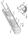
- Screen 20 and paddle 24 mounted on shaft 26 are shown in perspective view.
- Screen 20 in the preferred embodiment is formed of a sheet of type 306 stainless steel, with the thickness of the sheet dependent on the size of tumbler used. Alternate materials may be used for screen 20 depending on the design purpose of the apparatus, including plastic resins.
- Screen 20 as a sheet structure is formed with a plurality of openings therethrough of a size to allow appropriate size particles to pass and be sifted, or separated.
- Screen 20 is preferably in a semi-tubular shape, i.e. with a uniform radius concentric to axis K (see Figure 1 ) to conform to the turning radius of paddle 24 and maintain a maximum opening at the top of screen 20.
- a pair of channels 28 are formed along the upper edges of screen 20 to receive fasteners 22 (see Figure 1 ), with channels 28 residing diametrically outside of screen 20.
- screen 20 may be formed from a woven wire screen and/or formed in an arcuate or spherical shape, with paddle 24 shaped appropriately.
- Paddle 24 is preferably formed with a plurality of blades, e.g. 3 blades, each blade having one or more windows 25 formed therethrough.
- the windows 25 help to break down hard lumps and serve as passages to permit a portion of powder to pass through and a portion of powder adjacent to a solid frame section to be pushed forward, thus mixing the powder further.
- paddle 24 may be replaced with an auger type mixer that is substantially equal in diameter to the inside of screen 20. In the embodiment where paddle 24 may be replaced with an auger, windows may be provided to serve similar purposes.
- each blade of paddle 24 are formed at an angle X to the length of the blade in the radius direction, angle X being preferably in the range of 10[deg.] to 45[deg.].
- Angle X is oriented opposed to rotational direction B of paddle 24 so that as each blade passes screen 20, angle X presses some powder P through openings in screen 20 in a sifting operation.
- each blade of paddle 24 is formed at angle X further aids in the process of finely coating particles of powder P with a lubricating or protective layer, or coating fine particles of active ingredient on larger particles of inactive ingredient.
- paddle 24 is mounted to place the edge of each blade in close proximity to screen 20. As portions of each blade edge pass over the areas of screen 20 between openings, the powder particulate and coating material are rolled and squeezed into intimate contact to optimize the adhesion therebetween.
- Screen 20 is formed in an arcuate or semi-tubular shape with a channel 28 on opposed edges thereof.
- a series of cutters 32 are mounted radially on a shaft 34 that is mounted concentric with screen 20 and rotated. Cutters 32 may be tapered to form a sharp leading edge for breaking hard lumps and/or reducing the particle size of the ingredients while mixing.
- the invention disclosed herein is industrially applicable by improving the quality and uniformity of powder blending in the pharmaceutical industry.
- the invention provides an improved method according to claim 1 for blending a number of powders in a tumbler.
- the powders are alternately sifted through the screen and blended in the tumbler to produce a highly uniform powder blend.
- the industrial applicability extends further to the manufacture of the tumbler fitted with a fixed screen and rotatable paddle for use in practicing the method of the present invention.
- the best mode for practicing the invention comprises the steps of: a. placing a powder (P) batch to be sifted and blended into a closed rotatable tumbler (14) having a screen (20) fixedly mounted and a multiple-blade paddle (24) rotatably mounted therewithin, wherein the screen and the paddle are concentric with one another; b. forming the distal edges of the paddle blades at an angle to a radial length thereof; c.
- rotating the tumbler (14) to cause the powder (P) batch to drop alternately between a top and a bottom of the tumbler (14), first to catch a portion of powder (P) on the screen(20) and then to drop powder (P) from the screen (20) repeatedly to alternately sift and blend the powder (P); and d. rotating the paddle (24) in close proximity to the screen (20) to spread the powder (P) on the screen (20), promote sifting, and encourage adhesion between powder (P) particulate and a coating material; e. wherein different portions of powder (P) are randomly caught and dropped from the screen (20) in successive rotations of the tumbler (14).
Landscapes
- Chemical & Material Sciences (AREA)
- Chemical Kinetics & Catalysis (AREA)
- Physics & Mathematics (AREA)
- Geometry (AREA)
- Medical Preparation Storing Or Oral Administration Devices (AREA)
- Combined Means For Separation Of Solids (AREA)
- Separation Of Solids By Using Liquids Or Pneumatic Power (AREA)
Claims (8)
- Verfahren für abwechselndes Sieben und Mischen von Pulvern in einem einzelnen Vorgang, das die folgenden Schritte beinhaltet:a. Geben einer zu siebenden und zu mischenden Charge Pulver (P) in einen geschlossenen drehbaren Taumelbehälter (14) mit einem halbrohrförmigen Sieb (20), das fest montiert ist, und einem Rührwerk (24), das darinnen drehbar montiert ist,b. kontinuierliches Drehen des Taumelbehälters (14), um zu veranlassen, dass die Charge Pulver (P) abwechselnd zwischen einem oberen und einem unteren Ende des Taumelbehälters (14) nach unten fällt,c. Auffangen eines Teils des Pulvers (P) auf dem Sieb (20), während das Pulver (P) zum unteren Ende des Taumelbehälters (14) hin fallen gelassen wird,
wobei das Verfahren den folgenden Schritt aufweist:d. Drehen des Rührwerks (24) unabhängig von der Drehung des Taumelbehälters (14), um beim Drehen des Taumelbehälters (14) das Pulver (P) auf dem Sieb (20) zu verteilen und das Sieben zu fördern. - Verfahren nach Anspruch 1, wobei das Rührwerk (24) eine drehbare Paddel (24) aufweist, die mehrere Blätter hat, und der Schritt des Drehens des Rührwerks (24) das Drehen der Paddel (24) beinhaltet.
- Verfahren nach Anspruch 2, das ferner den Schritt des Montierens des Siebs (20) und der Paddel (24) konzentrisch zueinander beinhaltet.
- Verfahren nach Anspruch 2, wobei die Paddel (24) so ausgebildet ist, dass ein distaler Rand davon in einem Winkel zu einer radialen Länge davon ausgebildet ist, und der Schritt des Drehens der Paddel (24) ferner das Zwingen von Teilen des Pulvers (P) durch das Sieb (20) beinhaltet.
- Verfahren nach Anspruch 4, das ferner den Schritt des Drehens der Paddel (24) in enger Nähe zum Sieb (20) beinhaltet, um die Haftung zwischen Pulver- (P) - partikeln und einem Beschichtungsmaterial zu fördern.
- Verfahren nach einem der vorhergehenden Ansprüche, wobei verschiedene Teile des Pulvers (P) bei aufeinanderfolgenden Drehungen des Taumelbehälters (14) von dem Sieb (20) zufällig aufgefangen und fallengelassen werden.
- Vorrichtung für abwechselndes Sieben und Mischen von Pulvern in einem einzelnen Vorgang, umfassend: einen geschlossenen drehbaren Taumelbehälter (14) zum Aufnehmen einer zu siebenden und zu mischenden Charge Pulver (P), eine erste Antriebsvorrichtung zum kontinuierlichen Drehen des Taumelbehälters, um zu veranlassen, dass die Charge Pulver (P) abwechselnd zwischen einem oberen und einem unteren Ende des Taumelbehälters (14) nach unten fällt, ein Sieb (20), das fest innerhalb des Taumelbehälters (14) montiert ist, um beim Fallenlassen des Pulvers (P) zum unteren Ende des Taumelbehälters (14) hin einen Teil des Pulvers (P) auf dem Sieb (20) aufzufangen, und ein Rührwerk (24), dadurch gekennzeichnet, dass das Sieb ein halbrohrförmiges Sieb (20) ist, das Rührwerk (24) drehbar innerhalb des Taumelbehälters (14) montiert ist und die Vorrichtung eine zweite Antriebsvorrichtung aufweist, wobei die zweite Antriebsvorrichtung zum Drehen des Rührwerks (24) unabhängig von dem Taumelbehälter (14) betrieben werden kann, um das Pulver (P) auf dem Sieb (20) zu verteilen und das Sieben zu fördern, während die erste Antriebsvorrichtung den Taumelbehälter (14) dreht.
- Vorrichtung nach Anspruch 7, wobei das Rührwerk eine drehbare Paddel (24) aufweist, die mehrere Blätter hat.
Applications Claiming Priority (2)
| Application Number | Priority Date | Filing Date | Title |
|---|---|---|---|
| US10362108P | 2008-10-08 | 2008-10-08 | |
| PCT/US2009/005440 WO2010042151A2 (en) | 2008-10-08 | 2009-10-03 | Method for alternately sifting and blending powders in the same operation |
Publications (3)
| Publication Number | Publication Date |
|---|---|
| EP2346471A2 EP2346471A2 (de) | 2011-07-27 |
| EP2346471A4 EP2346471A4 (de) | 2014-03-12 |
| EP2346471B1 true EP2346471B1 (de) | 2015-09-30 |
Family
ID=42075717
Family Applications (1)
| Application Number | Title | Priority Date | Filing Date |
|---|---|---|---|
| EP09819539.9A Active EP2346471B1 (de) | 2008-10-08 | 2009-10-03 | Verfahren und vorrichtung für abwechselndes sieben und mischen von pulvern in einem prozess |
Country Status (4)
| Country | Link |
|---|---|
| US (1) | US8235582B2 (de) |
| EP (1) | EP2346471B1 (de) |
| CA (1) | CA2736942C (de) |
| WO (1) | WO2010042151A2 (de) |
Families Citing this family (9)
| Publication number | Priority date | Publication date | Assignee | Title |
|---|---|---|---|---|
| CN102406546B (zh) * | 2011-11-28 | 2013-07-24 | 河南省康星药业股份有限公司 | 超微粉定喘散常温制备方法 |
| US8827545B2 (en) | 2012-08-28 | 2014-09-09 | Sanyasi R. Kalidindi | Apparatus for alternately sifting and blending powders in the same operation |
| KR101470096B1 (ko) * | 2012-12-14 | 2014-12-05 | 현대자동차주식회사 | 나노복합재료 분산장치 |
| US20160370253A1 (en) * | 2015-06-19 | 2016-12-22 | Sanyasi R. Kalidindi | Powder segregation testing apparatus and method of using |
| CN106311040B (zh) * | 2015-06-23 | 2022-07-01 | 中国科学院过程工程研究所 | 一种交错抄板式混合器 |
| CN111841860B (zh) * | 2020-07-03 | 2024-11-01 | 长沙矿山研究院有限责任公司 | 一种粗骨料充填可选粒径圆振筛 |
| CN111789143A (zh) * | 2020-07-10 | 2020-10-20 | 青岛品品好食品发展有限公司 | 一种用于制作大米蛋糕的专用预拌粉 |
| CN114733759A (zh) * | 2022-03-25 | 2022-07-12 | 金雄(南通)智能科技有限公司 | 一种机械自动化原料筛选装置 |
| KR102807440B1 (ko) * | 2022-12-15 | 2025-05-19 | 주식회사와룡식품 | 원료 혼합기 |
Family Cites Families (19)
| Publication number | Priority date | Publication date | Assignee | Title |
|---|---|---|---|---|
| US192540A (en) * | 1877-06-26 | Improvement in rotary churns | ||
| US15455A (en) * | 1856-07-29 | Flour-bolt | ||
| US400621A (en) * | 1889-04-02 | winkler | ||
| US74954A (en) * | 1868-02-25 | Delphia wood | ||
| US269129A (en) * | 1882-12-12 | Nelson smith | ||
| US99985A (en) * | 1870-02-15 | Friedrich wegner and charles schleeter | ||
| US985A (en) * | 1838-10-19 | grieb and henry grieb | ||
| US79821A (en) * | 1868-07-14 | gilbert | ||
| US1593312A (en) * | 1926-05-27 | 1926-07-20 | Arthur C Shappell | Blender |
| GB427157A (en) * | 1933-08-04 | 1935-04-16 | Chem Ind Basel | Improvements in mixing mills |
| US2681210A (en) * | 1953-02-09 | 1954-06-15 | Alfred J Schaefer | Mixer and blender |
| GB875901A (en) * | 1959-06-04 | 1961-08-23 | Patterson Kelley Co | Liquids-solids blender |
| DK71478A (da) * | 1978-02-17 | 1979-08-18 | S Brams | Apparat til blanding og uddeling af faststoffer |
| SE9400335D0 (sv) * | 1994-02-02 | 1994-02-02 | Astra Ab | Powder mixing |
| KR0140014B1 (ko) | 1995-01-12 | 1998-06-01 | 황영진 | 회전 교반식 혼합기 |
| JP2003522636A (ja) * | 2000-02-17 | 2003-07-29 | アストラゼネカ ユーケー リミテッド | 混合装置および混合方法 |
| NZ502032A (en) * | 2000-04-23 | 2002-08-28 | Ind Res Ltd | Particulate solid material blender with rotatable closable bin having internal baffle |
| KR100769233B1 (ko) | 2005-01-17 | 2007-10-23 | 신명산업(주) | 분말혼합용 믹서 |
| US8016479B2 (en) * | 2005-07-25 | 2011-09-13 | Tokyo Printing Ink. Mfg. Co., Ltd. | Dispersing apparatus, dispersion method, and method of manufacturing dispersion |
-
2009
- 2009-10-03 EP EP09819539.9A patent/EP2346471B1/de active Active
- 2009-10-03 US US12/587,176 patent/US8235582B2/en active Active
- 2009-10-03 CA CA2736942A patent/CA2736942C/en active Active
- 2009-10-03 WO PCT/US2009/005440 patent/WO2010042151A2/en not_active Ceased
Also Published As
| Publication number | Publication date |
|---|---|
| EP2346471A4 (de) | 2014-03-12 |
| EP2346471A2 (de) | 2011-07-27 |
| CA2736942C (en) | 2013-02-05 |
| WO2010042151A2 (en) | 2010-04-15 |
| US8235582B2 (en) | 2012-08-07 |
| US20100085834A1 (en) | 2010-04-08 |
| WO2010042151A3 (en) | 2010-09-02 |
| CA2736942A1 (en) | 2010-04-15 |
Similar Documents
| Publication | Publication Date | Title |
|---|---|---|
| CA2736942C (en) | Method for alternately sifting and blending powders in the same operation | |
| US8827545B2 (en) | Apparatus for alternately sifting and blending powders in the same operation | |
| AU688861B2 (en) | Process and apparatus for mixing cohesive powders | |
| EP1191996B1 (de) | Knetmaschine mit dosiervorrichtung | |
| JP5192814B2 (ja) | 混練造粒機 | |
| US6042033A (en) | Apparatus for precise treatment of powder and particle | |
| CN102711974A (zh) | 带有轧碎板的混合机 | |
| AU687094B2 (en) | Materials mixer | |
| EP0450012B1 (de) | Einrichtung und verfahren zum mischen und/oder granulieren eines gutes | |
| US20030010217A1 (en) | Dough mixer with metering device | |
| JP6889924B2 (ja) | 撹拌混合装置 | |
| CN212596946U (zh) | 一种磷酸盐颗粒筛选装置 | |
| DE4341569C2 (de) | Vorrichtung zum Mischen oder Kneten von organischen Massen oder Teig | |
| JPH1015376A (ja) | 攪拌機 | |
| JPH08257382A (ja) | 粉粒体のミキサー | |
| CN215139526U (zh) | 一种反应釜输料装置 | |
| US5395058A (en) | Conditioning fertilizer hopper | |
| JP2004000839A (ja) | 粉粒体混合装置 | |
| EP2849558B1 (de) | Vertikaler wagen zur kombinierten zerkleinerungs und mischung | |
| DE4425297C2 (de) | Homogenisierungswerkzeug | |
| DE1239549B (de) | Vorrichtung zum Mischen von pulvrigen und stueckigen Stoffen | |
| DE19714209A1 (de) | Mischer zum kontinuierlichen Verarbeiten von fließfähigen Materialien |
Legal Events
| Date | Code | Title | Description |
|---|---|---|---|
| PUAI | Public reference made under article 153(3) epc to a published international application that has entered the european phase |
Free format text: ORIGINAL CODE: 0009012 |
|
| 17P | Request for examination filed |
Effective date: 20110420 |
|
| AK | Designated contracting states |
Kind code of ref document: A2 Designated state(s): AT BE BG CH CY CZ DE DK EE ES FI FR GB GR HR HU IE IS IT LI LT LU LV MC MK MT NL NO PL PT RO SE SI SK SM TR |
|
| AX | Request for extension of the european patent |
Extension state: AL BA RS |
|
| DAX | Request for extension of the european patent (deleted) | ||
| REG | Reference to a national code |
Ref country code: DE Ref legal event code: R079 Ref document number: 602009034149 Country of ref document: DE Free format text: PREVIOUS MAIN CLASS: A61J0003020000 Ipc: B07B0001240000 |
|
| A4 | Supplementary search report drawn up and despatched |
Effective date: 20140206 |
|
| RIC1 | Information provided on ipc code assigned before grant |
Ipc: B01F 9/04 20060101ALI20140131BHEP Ipc: B01F 9/00 20060101ALI20140131BHEP Ipc: B07B 1/24 20060101AFI20140131BHEP Ipc: B01F 9/08 20060101ALI20140131BHEP Ipc: B01F 3/18 20060101ALI20140131BHEP |
|
| GRAP | Despatch of communication of intention to grant a patent |
Free format text: ORIGINAL CODE: EPIDOSNIGR1 |
|
| INTG | Intention to grant announced |
Effective date: 20150414 |
|
| GRAS | Grant fee paid |
Free format text: ORIGINAL CODE: EPIDOSNIGR3 |
|
| GRAA | (expected) grant |
Free format text: ORIGINAL CODE: 0009210 |
|
| AK | Designated contracting states |
Kind code of ref document: B1 Designated state(s): AT BE BG CH CY CZ DE DK EE ES FI FR GB GR HR HU IE IS IT LI LT LU LV MC MK MT NL NO PL PT RO SE SI SK SM TR |
|
| REG | Reference to a national code |
Ref country code: CH Ref legal event code: EP Ref country code: GB Ref legal event code: FG4D |
|
| REG | Reference to a national code |
Ref country code: AT Ref legal event code: REF Ref document number: 752079 Country of ref document: AT Kind code of ref document: T Effective date: 20151015 |
|
| REG | Reference to a national code |
Ref country code: IE Ref legal event code: FG4D |
|
| REG | Reference to a national code |
Ref country code: DE Ref legal event code: R096 Ref document number: 602009034149 Country of ref document: DE |
|
| REG | Reference to a national code |
Ref country code: FR Ref legal event code: PLFP Year of fee payment: 7 |
|
| PG25 | Lapsed in a contracting state [announced via postgrant information from national office to epo] |
Ref country code: LV Free format text: LAPSE BECAUSE OF FAILURE TO SUBMIT A TRANSLATION OF THE DESCRIPTION OR TO PAY THE FEE WITHIN THE PRESCRIBED TIME-LIMIT Effective date: 20150930 Ref country code: FI Free format text: LAPSE BECAUSE OF FAILURE TO SUBMIT A TRANSLATION OF THE DESCRIPTION OR TO PAY THE FEE WITHIN THE PRESCRIBED TIME-LIMIT Effective date: 20150930 Ref country code: GR Free format text: LAPSE BECAUSE OF FAILURE TO SUBMIT A TRANSLATION OF THE DESCRIPTION OR TO PAY THE FEE WITHIN THE PRESCRIBED TIME-LIMIT Effective date: 20151231 Ref country code: NO Free format text: LAPSE BECAUSE OF FAILURE TO SUBMIT A TRANSLATION OF THE DESCRIPTION OR TO PAY THE FEE WITHIN THE PRESCRIBED TIME-LIMIT Effective date: 20151230 Ref country code: LT Free format text: LAPSE BECAUSE OF FAILURE TO SUBMIT A TRANSLATION OF THE DESCRIPTION OR TO PAY THE FEE WITHIN THE PRESCRIBED TIME-LIMIT Effective date: 20150930 |
|
| REG | Reference to a national code |
Ref country code: NL Ref legal event code: MP Effective date: 20150930 |
|
| REG | Reference to a national code |
Ref country code: LT Ref legal event code: MG4D |
|
| REG | Reference to a national code |
Ref country code: AT Ref legal event code: MK05 Ref document number: 752079 Country of ref document: AT Kind code of ref document: T Effective date: 20150930 |
|
| PG25 | Lapsed in a contracting state [announced via postgrant information from national office to epo] |
Ref country code: HR Free format text: LAPSE BECAUSE OF FAILURE TO SUBMIT A TRANSLATION OF THE DESCRIPTION OR TO PAY THE FEE WITHIN THE PRESCRIBED TIME-LIMIT Effective date: 20150930 Ref country code: SE Free format text: LAPSE BECAUSE OF FAILURE TO SUBMIT A TRANSLATION OF THE DESCRIPTION OR TO PAY THE FEE WITHIN THE PRESCRIBED TIME-LIMIT Effective date: 20150930 |
|
| PG25 | Lapsed in a contracting state [announced via postgrant information from national office to epo] |
Ref country code: EE Free format text: LAPSE BECAUSE OF FAILURE TO SUBMIT A TRANSLATION OF THE DESCRIPTION OR TO PAY THE FEE WITHIN THE PRESCRIBED TIME-LIMIT Effective date: 20150930 Ref country code: IS Free format text: LAPSE BECAUSE OF FAILURE TO SUBMIT A TRANSLATION OF THE DESCRIPTION OR TO PAY THE FEE WITHIN THE PRESCRIBED TIME-LIMIT Effective date: 20160130 Ref country code: IT Free format text: LAPSE BECAUSE OF FAILURE TO SUBMIT A TRANSLATION OF THE DESCRIPTION OR TO PAY THE FEE WITHIN THE PRESCRIBED TIME-LIMIT Effective date: 20150930 Ref country code: NL Free format text: LAPSE BECAUSE OF FAILURE TO SUBMIT A TRANSLATION OF THE DESCRIPTION OR TO PAY THE FEE WITHIN THE PRESCRIBED TIME-LIMIT Effective date: 20150930 Ref country code: SK Free format text: LAPSE BECAUSE OF FAILURE TO SUBMIT A TRANSLATION OF THE DESCRIPTION OR TO PAY THE FEE WITHIN THE PRESCRIBED TIME-LIMIT Effective date: 20150930 Ref country code: CZ Free format text: LAPSE BECAUSE OF FAILURE TO SUBMIT A TRANSLATION OF THE DESCRIPTION OR TO PAY THE FEE WITHIN THE PRESCRIBED TIME-LIMIT Effective date: 20150930 Ref country code: ES Free format text: LAPSE BECAUSE OF FAILURE TO SUBMIT A TRANSLATION OF THE DESCRIPTION OR TO PAY THE FEE WITHIN THE PRESCRIBED TIME-LIMIT Effective date: 20150930 |
|
| PG25 | Lapsed in a contracting state [announced via postgrant information from national office to epo] |
Ref country code: PL Free format text: LAPSE BECAUSE OF FAILURE TO SUBMIT A TRANSLATION OF THE DESCRIPTION OR TO PAY THE FEE WITHIN THE PRESCRIBED TIME-LIMIT Effective date: 20150930 Ref country code: RO Free format text: LAPSE BECAUSE OF FAILURE TO SUBMIT A TRANSLATION OF THE DESCRIPTION OR TO PAY THE FEE WITHIN THE PRESCRIBED TIME-LIMIT Effective date: 20150930 Ref country code: PT Free format text: LAPSE BECAUSE OF FAILURE TO SUBMIT A TRANSLATION OF THE DESCRIPTION OR TO PAY THE FEE WITHIN THE PRESCRIBED TIME-LIMIT Effective date: 20160201 Ref country code: AT Free format text: LAPSE BECAUSE OF FAILURE TO SUBMIT A TRANSLATION OF THE DESCRIPTION OR TO PAY THE FEE WITHIN THE PRESCRIBED TIME-LIMIT Effective date: 20150930 |
|
| REG | Reference to a national code |
Ref country code: CH Ref legal event code: PL |
|
| PG25 | Lapsed in a contracting state [announced via postgrant information from national office to epo] |
Ref country code: MC Free format text: LAPSE BECAUSE OF FAILURE TO SUBMIT A TRANSLATION OF THE DESCRIPTION OR TO PAY THE FEE WITHIN THE PRESCRIBED TIME-LIMIT Effective date: 20150930 |
|
| REG | Reference to a national code |
Ref country code: DE Ref legal event code: R097 Ref document number: 602009034149 Country of ref document: DE |
|
| REG | Reference to a national code |
Ref country code: IE Ref legal event code: MM4A |
|
| PG25 | Lapsed in a contracting state [announced via postgrant information from national office to epo] |
Ref country code: CH Free format text: LAPSE BECAUSE OF NON-PAYMENT OF DUE FEES Effective date: 20151031 Ref country code: LI Free format text: LAPSE BECAUSE OF NON-PAYMENT OF DUE FEES Effective date: 20151031 |
|
| PLBE | No opposition filed within time limit |
Free format text: ORIGINAL CODE: 0009261 |
|
| STAA | Information on the status of an ep patent application or granted ep patent |
Free format text: STATUS: NO OPPOSITION FILED WITHIN TIME LIMIT |
|
| PG25 | Lapsed in a contracting state [announced via postgrant information from national office to epo] |
Ref country code: DK Free format text: LAPSE BECAUSE OF FAILURE TO SUBMIT A TRANSLATION OF THE DESCRIPTION OR TO PAY THE FEE WITHIN THE PRESCRIBED TIME-LIMIT Effective date: 20150930 |
|
| 26N | No opposition filed |
Effective date: 20160701 |
|
| REG | Reference to a national code |
Ref country code: FR Ref legal event code: PLFP Year of fee payment: 8 |
|
| PG25 | Lapsed in a contracting state [announced via postgrant information from national office to epo] |
Ref country code: IE Free format text: LAPSE BECAUSE OF NON-PAYMENT OF DUE FEES Effective date: 20151003 |
|
| PG25 | Lapsed in a contracting state [announced via postgrant information from national office to epo] |
Ref country code: SI Free format text: LAPSE BECAUSE OF FAILURE TO SUBMIT A TRANSLATION OF THE DESCRIPTION OR TO PAY THE FEE WITHIN THE PRESCRIBED TIME-LIMIT Effective date: 20150930 |
|
| PG25 | Lapsed in a contracting state [announced via postgrant information from national office to epo] |
Ref country code: BE Free format text: LAPSE BECAUSE OF FAILURE TO SUBMIT A TRANSLATION OF THE DESCRIPTION OR TO PAY THE FEE WITHIN THE PRESCRIBED TIME-LIMIT Effective date: 20150930 |
|
| PG25 | Lapsed in a contracting state [announced via postgrant information from national office to epo] |
Ref country code: BG Free format text: LAPSE BECAUSE OF FAILURE TO SUBMIT A TRANSLATION OF THE DESCRIPTION OR TO PAY THE FEE WITHIN THE PRESCRIBED TIME-LIMIT Effective date: 20150930 Ref country code: SM Free format text: LAPSE BECAUSE OF FAILURE TO SUBMIT A TRANSLATION OF THE DESCRIPTION OR TO PAY THE FEE WITHIN THE PRESCRIBED TIME-LIMIT Effective date: 20150930 Ref country code: HU Free format text: LAPSE BECAUSE OF FAILURE TO SUBMIT A TRANSLATION OF THE DESCRIPTION OR TO PAY THE FEE WITHIN THE PRESCRIBED TIME-LIMIT; INVALID AB INITIO Effective date: 20091003 |
|
| PG25 | Lapsed in a contracting state [announced via postgrant information from national office to epo] |
Ref country code: CY Free format text: LAPSE BECAUSE OF FAILURE TO SUBMIT A TRANSLATION OF THE DESCRIPTION OR TO PAY THE FEE WITHIN THE PRESCRIBED TIME-LIMIT Effective date: 20150930 |
|
| PG25 | Lapsed in a contracting state [announced via postgrant information from national office to epo] |
Ref country code: TR Free format text: LAPSE BECAUSE OF FAILURE TO SUBMIT A TRANSLATION OF THE DESCRIPTION OR TO PAY THE FEE WITHIN THE PRESCRIBED TIME-LIMIT Effective date: 20150930 Ref country code: MT Free format text: LAPSE BECAUSE OF FAILURE TO SUBMIT A TRANSLATION OF THE DESCRIPTION OR TO PAY THE FEE WITHIN THE PRESCRIBED TIME-LIMIT Effective date: 20150930 |
|
| REG | Reference to a national code |
Ref country code: FR Ref legal event code: PLFP Year of fee payment: 9 |
|
| PG25 | Lapsed in a contracting state [announced via postgrant information from national office to epo] |
Ref country code: LU Free format text: LAPSE BECAUSE OF NON-PAYMENT OF DUE FEES Effective date: 20151003 |
|
| PG25 | Lapsed in a contracting state [announced via postgrant information from national office to epo] |
Ref country code: MK Free format text: LAPSE BECAUSE OF FAILURE TO SUBMIT A TRANSLATION OF THE DESCRIPTION OR TO PAY THE FEE WITHIN THE PRESCRIBED TIME-LIMIT Effective date: 20150930 |
|
| REG | Reference to a national code |
Ref country code: FR Ref legal event code: PLFP Year of fee payment: 10 |
|
| REG | Reference to a national code |
Ref country code: DE Ref legal event code: R082 Ref document number: 602009034149 Country of ref document: DE Representative=s name: VENNER SHIPLEY GERMANY LLP, DE Ref country code: DE Ref legal event code: R082 Ref document number: 602009034149 Country of ref document: DE Representative=s name: VENNER SHIPLEY LLP, DE |
|
| PGFP | Annual fee paid to national office [announced via postgrant information from national office to epo] |
Ref country code: DE Payment date: 20251029 Year of fee payment: 17 |
|
| PGFP | Annual fee paid to national office [announced via postgrant information from national office to epo] |
Ref country code: GB Payment date: 20251027 Year of fee payment: 17 |
|
| PGFP | Annual fee paid to national office [announced via postgrant information from national office to epo] |
Ref country code: FR Payment date: 20251027 Year of fee payment: 17 |