EP2345782A1 - Anti-Panik-Zylinder - Google Patents
Anti-Panik-Zylinder Download PDFInfo
- Publication number
- EP2345782A1 EP2345782A1 EP10014493A EP10014493A EP2345782A1 EP 2345782 A1 EP2345782 A1 EP 2345782A1 EP 10014493 A EP10014493 A EP 10014493A EP 10014493 A EP10014493 A EP 10014493A EP 2345782 A1 EP2345782 A1 EP 2345782A1
- Authority
- EP
- European Patent Office
- Prior art keywords
- cylinder
- panic
- sleeve
- locking lug
- core
- Prior art date
- Legal status (The legal status is an assumption and is not a legal conclusion. Google has not performed a legal analysis and makes no representation as to the accuracy of the status listed.)
- Granted
Links
Images

Classifications
-
- E—FIXED CONSTRUCTIONS
- E05—LOCKS; KEYS; WINDOW OR DOOR FITTINGS; SAFES
- E05B—LOCKS; ACCESSORIES THEREFOR; HANDCUFFS
- E05B17/00—Accessories in connection with locks
- E05B17/04—Devices for coupling the turning cylinder of a single or a double cylinder lock with the bolt operating member
- E05B17/047—Devices for coupling the turning cylinder of a single or a double cylinder lock with the bolt operating member with rotating output elements forming part of cylinder locks, e.g. locking cams of double cylinder locks
-
- E—FIXED CONSTRUCTIONS
- E05—LOCKS; KEYS; WINDOW OR DOOR FITTINGS; SAFES
- E05B—LOCKS; ACCESSORIES THEREFOR; HANDCUFFS
- E05B65/00—Locks or fastenings for special use
- E05B65/10—Locks or fastenings for special use for panic or emergency doors
- E05B65/1086—Locks with panic function, e.g. allowing opening from the inside without a ley even when locked from the outside
Definitions
- the invention relates to a digital anti-panic cylinder with a cylinder housing, a cylinder housing received, rotatably mounted in the cylinder housing cylinder core, a rotatably arranged locking lug, a connecting in the presence of the lock authorization the cylinder core with the locking lug coupling, and a closing lug when not in operation Anti-panic cylinder in a predetermined position adjusting return mechanism.
- Self-locking anti-panic locks are known as key-operated variants equipped with a mechanical locking cylinder and as electronic variants equipped with a digital locking cylinder. They have in common that the equipped with these locking systems doors from the outside - as is well known - can only be opened with a key or by transmitting a digital access authorization, whereas the door from the inside can be opened at any time by pressing the door handle and again automatically locked as soon as the door has fallen back into the lock.
- the locking lug also called closing cam or driver
- the locking lug is arranged in non-actuation of the lock cylinder in a position in which the locking lug the anti-panic Function of the lock can not block.
- Such a reset device for the locking lug digital anti-panic locking systems is for example from the DE 10 2004 048 231 B4 known.
- a spring arranged in the knob of a return device designed as a half-cylinder acts on the closing nose via a helically wound element connected to a guide element such that the closing nose is turned back into a rest position after actuation of a digital locking cylinder combined with the return device, also in the form of a half-cylinder the anti-panic function of the lock is not obstructed or even blocked.
- Object of the present invention is therefore to provide an anti-panic cylinder, which is protected from manipulation from the outside, preferably easy to manufacture and install and is particularly preferably closed on both sides.
- the anti-panic cylinder having the features of claim 1.
- the subclaims reflect advantageous embodiments of the invention.
- the basic idea of the invention is to arrange the return mechanism in the cylinder housing of a digital anti-panic closing latch so that the cylinder core can be largely kept free of the components of the return mechanism acting on the closing nose. So it is possible to produce a digital half-cylinder with integrated lock-reset mechanism.
- a simple manufacture, installation and a compact structure with improved protection against manipulation is achieved.
- the inventive design of the digital anti-panic lock cylinder allows in a configuration as a double cylinder lockability of a equipped with the anti-panic invention lock from both sides of a door.
- Fig. 1 shows a schematic sectional view of a portion of the digital anti-panic cylinder according to the invention.
- the digital anti-panic cylinder 10 has a cylinder housing 20 and a cylinder housing 30 rotatably mounted in the cylinder housing.
- An arranged in the cylinder core 30 closing electronics 100 is used to query or for receiving and / or processing a digital Sch.berecht Trent signal by coupling the cylinder core 30 with the locking lug 40th
- the return mechanism ensuring the anti-panic function is formed from the sleeve 50 surrounding the cylinder core 30 and the actuating element 60 which acts on the sleeve 50 and is acted upon by the force of a spring 70.
- a single spring 70 or at least two serially arranged springs can be used with different spring force whose working range is associated with a specific angular position of the locking lug.
- the sleeve 50 is received by the cylinder housing 20 and rotatably mounted in this. It is connected with its one side with the locking lug 40, so that rotation of the sleeve 50 inevitably leads to a rotation of the locking lug 40.
- the actuator 60 is also received by the cylinder housing 20, but slidably mounted in this manner that the actuator 60 acts through the force acting directly on the actuator 60 force of the spring 70 on the sleeve 50 so that by relaxing the spring 70 a position of the sleeve 50 is enforced, wherein the locking lug 40 is arranged in a preferred lower position.
- This position can also be a predefined area in which the locking lug 40 is brought to its rest position.
- the actuator 60 is slidably disposed in the axial direction of the sleeve 50 with respect to the longitudinal axis of the cylinder. In contrast to a set perpendicular to the cylinder axis displaceability of the actuator 60 is set up for a set in the axial direction of the actuator 60 more space, so more spring can be held by a greater spring length for moving the locking lug 50 in the rest position.
- the sleeve 50 - as in Fig. 1 shown - an obliquely about the longitudinal axis of the sleeve 50 extending groove 80 into which the actuator 60 engages. It is understood that the connection of sleeve 50 and locking lug 40 must be made such that the rest position of the locking lug 40 is reached at maximum relaxed spring 70 and the groove 80 must be introduced into the outer wall of the sleeve 50 such that the actuator 60 is securely guided in the groove 80 and can not jump out of this.
- the use of a displaceably arranged in the axial direction of the cylinder 10 spring-loaded actuating element 60 in the direction of the locking lug 40 is possible in principle.
- the in Fig. 1 illustrated embodiment of the inventive anti-panic cylinder 10 are further improved when the spring 70, the actuator 60 is not acted upon in the direction of the locking lug 40 with the spring force, but actuator 60 and spring 70 are arranged vice versa, so that the spring force away from the locking lug 40 acts on the actuator 60.
- no forces acting laterally on the closing lug 40 occur in the resting state, as a result of which the wear of the cylinder components can be reduced.
- the actuating element 60 is formed from a base body and a receptacle occupied by an ellipsoid, wherein the Ellipsoid acts on the actuator 60 (in Fig. 1 indicated).
- the ellipsoid is rotatably mounted in the receptacle, which is preferably made with a clearance, that is to say a movement clearance.
- the ellipsoid is formed as a ball, but may also have other shapes.
- the digital anti-panic cylinder 10 according to the invention can be designed as a half-cylinder or preferably also as a double cylinder which can be closed from both sides.
- the digital anti-panic cylinder 10 according to the invention is designed as a half-cylinder, no further return mechanism made, for example, as a half-cylinder is required.
- the digital anti-panic cylinder 10 according to the invention is designed as a double cylinder that can be closed from both sides, it is advantageous for safety reasons to form the cylinder housing of the anti-panic cylinder in one piece and thus to make it more difficult to destroy the cylinder according to the invention installed in a door , It also makes it possible to move the part of the cylinder (often the knob), which has the closing electronics, on the inside of a door and thus make modifications from the outside inaccessible.
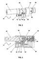
- Fig. 2 shows a perspective view of an anti-panic cylinder according to a second embodiment without a cylinder housing, whereas the installation situation of this anti-panic cylinder in the cylinder housing in longitudinal section in Fig. 3 is shown.
- the in the Fig. 2 and Fig. 3 shown anti-panic cylinder 10 ' has - as well as in Fig. 1 shown embodiment - a cylinder housing 20 'and a cylinder housing 20' rotatably mounted in the cylinder core 30 '.
- the anti-panic cylinder 10 ' also has a closing electronics, which has a coupling mechanism 90, with which the cylinder core 30' with the locking lug 40 'can be coupled.
- the cylinder core 30 ' is coupled to the closing nose 40' so that the lock having the anti-panic cylinder 10 'can be opened, for example, by actuating a knob connected to the cylinder core 30'.
- the anti-panic cylinder 10 ' also has a cylinder core 30' surrounding sleeve 50 ', which is received by the cylinder housing 20' and rotatably mounted therein.
- the sleeve 50 ' is also connected with its one side with the locking lug 40', so that rotation of the sleeve 50 'inevitably causes the rotation of the locking lug 40'.
- the anti-panic cylinder 10' also has a on the sleeve 50 'by the force of a spring 70' acting actuator 60 'on.
- this adjusting element 60 ' engages in contrast to the in Fig. 1 embodiment shown not in an introduced into the outer wall of the sleeve groove, but is supported against a on the Sleeve 50 'arranged control edge.
- the control edge of the sleeve 50 ' is most easily formed by obliquely cutting the sleeve.
- the spring 70 ' is preferably mounted against a first abutment 74' and a particularly preferably with the adjusting element 60 'connected to the axis 72' surrounding guide sleeve 76 '.
- the spring 70 ' can be prestressed in the cylinder housing 20' by means of the first abutment 74 '.
- the sleeve 50' on your the locking lug 40 'facing Side preferably provided with a perpendicular to the longitudinal axis of the cylinder core 30 'extending edge against which a bearing member 62' is supported such that the portion of the sleeve 50 'from the control edge to perpendicular to the longitudinal axis of the cylinder core 30' extending edge between the actuator 60th 'and the bearing element 62' is added.
- the bearing element 62 ' is particularly preferably fixed on the axis 72' arranged parallel to the cylinder core 30 '.
- the coupling 90 provided for connecting the cylinder core 30 'to the closing nose 40' has a device for permanently connecting the cylinder core 30 'to the closing nose 40'.
- This device is preferably realized in that the engaging in the locking lug 40 'coupling part by means of a fastener 92 in a first position in which an induced by the closing electronics input and decoupling of the locking lug 40' with the cylinder core 30 'is possible, or in a second position, in which the locking lug 40 'is permanently coupled to the cylinder core 30' is fixed.
- the fastening means 92 may be, for example, a (maggot) screw 92 accessible from outside the cylinder housing 20 'and arranged in a slot, which determines the relative position of the coupling part with respect to the locking lug 40' and the cylinder core 30 ', respectively.
- the spring 94 is preferably connected via a hub with the shaft of a motor which biases the spring 94 and the coupling member moves to the desired position in which the coupling part by means of the fastening means 92 relative to the locking lug 40 'is fixed.
- Both embodiments have the advantage that a designed as a half or double cylinder lock cylinder can be equipped with an anti-panic function, wherein the cylinder core is largely kept free of the components of acting on the locking cam return mechanism.
- a lockability of a equipped with the anti-panic invention cylinder lock from both sides of a door is possible.
Landscapes
- Lock And Its Accessories (AREA)
Abstract
Description
- Die Erfindung betrifft einen digitalen Anti-Panik-Zylinder mit einem Zylindergehäuse, einem vom Zylindergehäuse aufgenommenen, im Zylindergehäuse drehbar angeordneten Zylinderkern, einer drehbar angeordneten Schließnase, einer bei Vorliegen der Schließberechtigung den Zylinderkern mit der Schließnase verbindenden Kupplung, und einem die Schließnase bei Nichtbetätigung des Anti-Panik-Zylinders in eine vorbestimmte Position stellenden Rückstellmechanismus.
- Selbstverriegelnde Anti-Panik-Schlösser sind als schlüsselbetätigte, mit einem mechanischen Schließzylinder ausgestattete Varianten und als elektronische, mit einem digitalen Schließzylinder ausgerüstete Varianten bekannt. Ihnen ist gemeinsam, dass sich die mit diesen Schließsystemen ausgerüsteten Türen von der Außenseite - wie allgemein bekannt - nur mit einem Schlüssel oder durch Übermittlung einer digitalen Zugangsberechtigung öffnen lassen, wohingegen die Tür von der Innenseite jederzeit durch Betätigen des Türdrückers geöffnet werden kann und sich wieder selbsttätig verriegelt, sobald die Tür zurück ins Schloss gefallen ist.
- Damit die Anti-Panik-Funktion einer mit einem derartigen Schlosses ausgestatteten Tür erhalten bleibt, ist es notwendig, dass die Schließnase (auch Schließnocken oder Mitnehmer genannt) bei Nichtbetätigen des Schließzylinders in einer Position angeordnet ist, in der die Schließnase die Anti-Panik-Funktion des Schlosses nicht blockieren kann.
- Bei schlüsselbetätigten Schließzylindern erfolgt dieses durch eine bei Schlüsselabzug vordefinierte, in der Regel im Schließzylinder untere Positionierung der Schließnase. Bei digitalen Schließzylindern hingegen, bei denen der Außendrehknopf ohne Schließberechtigung frei drehbar ist und nur bei Vorliegen einer Schließberechtigung mit der Schließnase gekuppelt wird, muss durch zusätzliche konstruktive Maßnahmen sichergestellt werden, dass die Schließnase nach dem Schließvorgang in eine neutrale, die Anti-Panik-Funktion nicht behindernde Ausgangsposition zurückkehrt.
- Eine derartige Rückstellvorrichtung für die Schließnase digitaler Anti-Panik-Schließsysteme ist beispielsweise aus der
DE 10 2004 048 231 B4 bekannt. Hier wirkt eine im Knauf einer als Halbzylinder ausgebildeten Rückstellvorrichtung angeordnete Feder über ein mit einem Führungselement verbundenes helixförmig gewundenes Element derart auf die Schließnase, dass die Schließnase nach Betätigung eines mit der Rückstellvorrichtung kombinierten, ebenfalls als Halbzylinder ausgebildeten digitalen Schließzylinders in eine Ruheposition zurück gedreht wird und die Anti-Panik-Funktion des Schlosses nicht behindert oder sogar blockiert wird. - Insbesondere sieht die
DE 10 2004 048 231 B4 also vor, dass auf der Außenseite der Tür ein als Halbzylinder ausgebildeter digitaler Schließzylinder zum Öffnen der Tür bei Vorliegen einer Schließberechtigung und auf der Innenseite der Tür eine als Halbzylinder ausgebildete Rückstellvorrichtung angeordnet ist, die die Schließnase in eine vorbestimmte Position drängt, sobald der digitale Schließzylinder nicht betätigt wird. - Nachteilig an dieser Konstruktion ist jedoch, dass die Elektronik des digitalen Schließzylinders zwingend auf der Außenseite der Tür angeordnet werden muss und daher für Manipulationen leicht zugänglich ist. Darüber hinaus ist für derartig ausgerüstete Anti-Panik-Schlösser sowohl die Herstellung als auch die Installation sehr aufwändig. Schließlich wäre es unter Sicherheitsaspekten auch wünschenswert, ein Anti-Panik-Schloss verwenden zu können, dass ein Abschließen der Tür auch auf der Innenseite erlaubt und so einen Zugang von Außen verhindert.
- Aufgabe der vorliegenden Erfindung ist es daher, einen Anti-Panik-Zylinder zu schaffen, der vor Manipulationen von der Außenseite geschützt, bevorzugt einfach herzustellen und zu installieren und besonders bevorzugt beidseitig schließbar ist.
- Diese Aufgabe wird durch den Anti-Panik-Zylinder mit den Merkmalen von Anspruch 1 gelöst. Die Unteransprüche geben vorteilhafte Ausgestaltungen der Erfindung wieder. Grundgedanke der Erfindung ist es, den Rückstellmechanismus im Zylindergehäuse eines digitalen Anti-Panik-Schließzaylinders derart anzuordnen, dass der Zylinderkern weitgehend von den Komponenten des auf die Schließnase wirkenden Rückstellmechanismus freigehalten werden kann. So ist es möglich einen digitalen Halbzylinder mit integriertem Schließnasen-Rückstellmechanismus herzustellen. Darüber hinaus wird eine einfache Herstellung, Installation und ein kompakter Aufbau mit einem verbesserten Schutz vor Manipulation erreicht. Schließlich ermöglicht die erfindungsgemäße Ausgestaltung des digitalen Anti-Panik-Schließzylinders bei einer Ausgestaltung als Doppelzylinder eine Schließbarkeit eines mit dem erfindungsgemäßen Anti-Panik-Zylinders ausgerüsteten Schlosses von beiden Seiten einer Tür.
- Die Erfindung wird anhand von in den beigefügten Zeichnungen dargestellten besonders bevorzugten Ausführungsbeispielen näher erläutert. Es zeigen:
- Fig. 1
- eine schematische Schnittansicht eines Teilbereichs des digitalen Anti-Panik-Zylinders nach einem ersten Ausführungsbeispiel;
- Fig. 2
- eine perspektivische Ansicht eines Anti-Panik-Zylinders nach einem zweiten Ausführungsbeispiel ohne Zylindergehäuse; und
- Fig. 3
- einen Längsschnitt durch den Anti-Panik-Zylinder nach dem zweiten Ausführungsbeispiel mit Zylindergehäuse.
-
Fig. 1 zeigt eine schematische Schnittansicht eines Teilbereichs des digitalen Anti-Panik-Zylinders nach der Erfindung. - Der digitale Anti-Panik-Zylinder 10 weist ein Zylindergehäuse 20 und einen im Zylindergehäuse drehbar gelagerten Zylinderkern 30 auf. Eine im Zylinderkern 30 angeordnete Schließelektronik 100 dient zur Abfrage bzw. zum Empfang und/oder der Verarbeitung eines digitalen Schließberechtigung-Signals durch Kupplung des Zylinderkerns 30 mit der Schließnase 40.
- Der die Anti-Panik-Funktion gewährleistende Rückstellmechanismus ist aus der den Zylinderkern 30 umgebenden Hülse 50 und dem auf die Hülse 50 wirkenden, mit der Kraft einer Feder 70 beaufschlagten Stellelement 60 gebildet. Hierfür können eine einzige Feder 70 oder wenigstens zwei seriell angeordnete Federn (nicht dargestellt) mit unterschiedlicher Federkraft verwendet werden, deren Arbeitsbereich einer bestimmten Winkelstellung der Schließnase zugeordnet ist.
- Die Hülse 50 ist vom Zylindergehäuse 20 aufgenommen und in diesem drehbar gelagert. Sie ist mit ihrer einen Seite mit der Schließnase 40 verbunden, sodass eine Drehung der Hülse 50 zwangsläufig auch zu einer Drehung der Schließnase 40 führt.
- Das Stellelement 60 ist ebenfalls vom Zylindergehäuse 20 aufgenommen, in diesem allerdings verschieblich derart gelagert, dass das Stellelement 60 durch die unmittelbar auf das Stellelement 60 wirkende Kraft der Feder 70 auf die Hülse 50 so einwirkt, dass durch Entspannen der Feder 70 eine Position der Hülse 50 erzwungen wird, bei der die Schließnase 40 in einer bevorzugt unteren Position angeordnet ist. Diese Position kann auch ein vordefinierter Bereich sein, in dem die Schließnase 40 in ihre Ruhestellung verbracht wird.
- Das Stellelement 60 ist in Bezug auf die Längsachse des Zylinders in axialer Richtung auf die Hülse 50 wirkend verschieblich angeordnet. Im Gegensatz zu einer senkrecht zur Zylinderachse eingerichteten Verschieblichkeit des Stellelements 60 ist für eine in axialer Richtung eingerichtete Verschieblichkeit des Stellelements 60 mehr Platz, sodass durch eine größere Federlänge mehr Kraft zum Verbringen der Schließnase 50 in die Ruheposition vorgehalten werden kann.
- Erfindungsgemäß weist die Hülse 50 - wie in
Fig. 1 dargestellt - eine schräg um die Längsachse der Hülse 50 verlaufende Nut 80 auf, in die das Stellelement 60 eingreift. Es versteht sich, dass die Verbindung von Hülse 50 und Schließnase 40 derart erfolgen muss, dass die Ruheposition der Schließnase 40 bei maximal entspannter Feder 70 erreicht wird und die Nut 80 derart in die Außenwandung der Hülse 50 eingebracht sein muss, dass das Stellelement 60 sicher in der Nut 80 geführt wird und aus dieser nicht herausspringen kann. - Bei dieser Ausgestaltung ist die Verwendung eines in axialer Richtung des Zylinders 10 verschieblich angeordneten federbelasteten Stellelements 60 in Richtung der Schließnase 40 grundsätzlich möglich. Diesbezüglich kann die in
Fig. 1 dargestellte Ausgestaltung des erfindungsgemäßen Anti-Panik-Zylinders 10 noch weiter verbessert werden, wenn die Feder 70 das Stellelement 60 nicht in Richtung der Schließnase 40 mit der Federkraft beaufschlagt, sondern Stellelement 60 und Feder 70 umgekehrt angeordnet sind, sodass die Federkraft weg von der Schließnase 40 auf das Stellelement 60 wirkt. Dadurch treten im Ruhezustand keine auf die Schließnase 40 seitlich wirkenden Kräfte auf, wodurch der Verschleiß der Zylinderkomponenten verringert werden kann. - Um bei Drehung der Schließnase 40 aus der Ruheposition um 180° einen Totpunkt zu vermeiden, an dem die Schließnase 40 dauerhaft verbleiben kann, ist besonders bevorzugt vorgesehen, dass das Stellelement 60 aus einem Grundkörper und einer von einem Ellipsoid eingenommene Aufnahme gebildet ist, wobei das Ellipsoid auf das Stellelement 60 wirkt (in
Fig. 1 angedeutet). Das Ellipsoid ist in der bevorzugt mit einem Spiel, also einem Bewegungsfreiraum, gefertigten Aufnahme drehbar gelagert. Besonders bevorzugt ist das Ellpsoid als Kugel ausgebildet, kann jedoch auch andere Formen aufweisen. Der Totpunkt wird nun dadurch vermieden werden, dass das Ellipsoid in der mit Spiel gefertigten Aufnahme dazu neigt, sich der auf das Ellipsoid wirkenden Gegenkraft der Hülse 50 zu entziehen. Hierdurch wird die Zuverlässigkeit bzw. Sicherheit der Anti-Panik-Funktion verbessert. - Der erfindungsgemäβe digitale Anti-Panik-Zylinder 10 kann als Halbzylinder oder bevorzugt auch als von beiden Seiten schließbarer Doppelzylinder ausgebildet sein.
- Ist der erfindungsgemäße digitale Anti-Panik-Zylinder 10 als Halbzylinder ausgebildet, wird kein weiterer z.B. als Halbzylinder gefertigter Rückstellmechanismus benötigt.
- Ist der erfindungsgemäße digitale Anti-Panik-Zylinder 10 hingegen als von beiden Seiten schließbarer Doppelzylinder ausgebildet, ist es aus sicherheitstechnischen Überlegungen von Vorteil, das Zylindergehäuse des Anti-Panik-Zylinders einstückig auszubilden und so die Zerstörung des in eine Tür eingebauten erfindungsgemäßen Zylinders zu erschweren. Außerdem ist es ermöglicht, den Teil des Zylinders (oftmals der Knauf), der die Schließelektronik aufweist, auf die Innenseite einer Tür zu verlagern und somit Modifikationen von Außen unzugänglich zu machen.
-
Fig. 2 zeigt eine perspektivische Ansicht eines Anti-Panik-Zylinders nach einem zweiten Ausführungsbeispiel ohne Zylindergehäuse, wohingegen die Einbausituation dieses Anti-Panik-Zylinders im Zylindergehäuse im Längsschnitt inFig. 3 dargestellt ist. - Der in den
Fig. 2 und Fig. 3 dargestellte Anti-Panik-Zylinder 10' weist - wie auch das inFig. 1 gezeigte Ausführungsbeispiel - ein Zylindergehäuse 20' und einen im Zylindergehäuse 20' drehbar gelagerten Zylinderkern 30' auf. Der Anti-Panik-Zylinder 10' weist ebenfalls eine Schließelektronik auf, die über einen Kupplungsmechanismus 90 verfügt, mit dem der Zylinderkern 30' mit der Schließnase 40' gekuppelt werden kann. Bei Vorliegen einer Schließberechtigung wird also der Zylinderkern 30' mit der Schließnase 40' gekoppelt, sodass das den Anti-Panik-Zylinder 10' aufweisende Schloss beispielsweise durch Betätigen eines mit dem Zylinderkern 30' verbundenen Knaufs geöffnet werden kann. - Der Anti-Panik-Zylinder 10'weist auch eine den Zylinderkern 30' umgebende Hülse 50' auf, die vom Zylindergehäuse 20' aufgenommen und in diesem drehbar gelagert ist. Die Hülse 50' ist ebenfalls mit ihrer einen Seite mit der Schließnase 40' verbunden, sodass eine Drehung der Hülse 50' zwangsläufig auch die Drehung der Schließnase 40' bewirkt.
- Zur Einnahme der für die Funktion eines Anti-Panik-Zylinders notwendigen Position der Schließnase 40' weist der Anti-Panik-Zylinder 10' darüber hinaus auch ein auf die Hülse 50' mittels der Kraft einer Feder 70' wirkendes Stellelement 60' auf. Allerdings greift dieses Stellelement 60' im Gegensatz zu dem in
Fig. 1 gezeigten Ausführungsbeispiel nicht in eine in die Außenwandung der Hülse eingebrachte Nut, sondern stützt sich gegen eine an der Hülse 50' angeordnete Steuerkante. Die Steuerkante der Hülse 50' ist am einfachsten dadurch zu bilden, dass die Hülse schräg abgelängt wird. - Bevorzugt ist das Stellelement 60'auf einer parallel zum Zylinderkern 30' verlaufenden Achse 72' verschieblich gegen die Kraft der Feder 70' gelagert. Die Feder 70' ist bevorzugt gegen ein erstes Widerlager 74' und eine besonders bevorzugt mit dem Stellelement 60' verbundene, die Achse 72' umgebende Führungshülse 76' gelagert. Besonders bevorzugt kann die Feder 70'mittels des ersten Widerlagers 74' im Zylindergehäuse 20' vorgespannt werden.
- Um eine möglichst gleichmäßige, dauerhaft wiederholbare Drehung und eine verschleißunanfällige Drehbarkeit der Hülse 50' zu gewährleisten, sowie um von der Längsachse der parallel zum Zylinderkern 30' verlaufenden Achse 72' abweichenden Querkräften vorzubeugen, ist die Hülse 50' auf Ihrer der Schließnase 40' zugewandten Seite bevorzugt mit einer senkrecht zur Längsachse des Zylinderkerns 30' verlaufenden Kante versehen, gegen die sich ein Lagerelement 62' derart abstützt, dass der Abschnitt der Hülse 50' von der Steuerkante bis zur senkrecht zur Längsachse des Zylinderkerns 30' verlaufenden Kante zwischen dem Stellelement 60' und dem Lagerelement 62' aufgenommen ist. Dabei ist das Lagerelement 62' besonders bevorzugt auf der parallel zum Zylinderkern 30' angeordneten Achse 72' fixiert.
- Als eine Besonderheit ist in diesem zweiten Ausführungsbeispiel vorgesehen, dass die zum Verbinden des Zylinderkerns 30' mit der Schließnase 40' eingerichtete Kupplung 90 eine Einrichtung zum dauerhaften Verbinden des Zylinderkerns 30' mit der Schließnase 40' aufweist. Diese Einrichtung wird bevorzugt dadurch realisiert, dass das in die Schließnase 40' eingreifende Kupplungsteil mit Hilfe eines Befestigungsmittels 92 in einer ersten Position, in der ein durch die Schließelektronik veranlasstes Ein- und Entkoppeln der Schließnase 40' mit dem Zylinderkern 30' ermöglicht ist, oder in einer zweiten Position, in der die Schließnase 40' dauerhaft mit dem Zylinderkern 30' gekuppelt ist, fixiert wird.
- Das Befestigungsmittel 92 kann beispielsweise eine von außerhalb des Zylindergehäuses 20' zugängliche, in einem Langloch angeordnete (Maden-) Schraube 92 sein, die die relative Position des Kupplungsteils in Bezug auf die Schließnase 40' bzw. den Zylinderkern 30' bestimmt. Hierfür ist die Feder 94 bevorzugt über eine Nabe mit der Welle eines Motors verbunden, der die Feder 94 vorspannt und das Kupplungsteil in die gewünschte Position verschiebt, in der das Kupplungsteil mit Hilfe des Befestigungsmittels 92 relativ zur Schließnase 40' fixiert wird.
- Mit diesem einen Ausführungsbeispiel des Anti-Panik-Zylinders 10' können also auch solche Türen bestückt werden, die lediglich als Durchgangstür dienen und bei denen der Innenknauf und der Außenknauf gleichzeitig einkuppelbar sind, sodass das Schloss sowohl von der einen als auch von der anderen Seite der Tür bedient und die Tür geöffnet werden kann.
- Beide Ausführungsbeispiele haben den Vorteil, dass ein als Halb- oder Doppelzylinder ausgebildeter Schließzylinder mit einer Anti-Panik-Funktion ausgerüstet werden kann, wobei der Zylinderkern weitgehend von den Komponenten des auf die Schließnase wirkenden Rückstellmechanismus freigehalten wird. So ist auch bei einer Ausgestaltung als Doppelzylinder eine Schließbarkeit eines mit dem erfindungsgemäßen Anti-Panik-Zylinders ausgerüsteten Schlosses von beiden Seiten einer Tür möglich.
Claims (13)
- Digitaler Anti-Panik-Zylinder (10) mit- einem Zylindergehäuse (20),- einem vom Zylindergehäuse (20) aufgenommenen, im Zylindergehäuse (20) drehbar angeordneten Zylinderkern (30),- einer drehbar angeordneten Schließnase (40),- einer bei Vorliegen der Schließberechtigung den Zylinderkern (30) mit der Schließnase (40) verbindenden Kupplung, und- einem die Schließnase (40) bei Nichtbetätigung des Anti-Panik-Zylinders (10) in eine vorbestimmte Position stellenden Rückstellmechanismus,dadurch gekennzeichnet, dass
der Rückstellmechanismus aus- einer vom Zylindergehäuse (20) aufgenommenen, drehbar angeordneten Hülse (50), die einen sich in axialer Richtung erstreckenden Abschnitt des Zylinderkerns (30) umgibt, auf ihrer einen Seite mit der Schließnase (40) verbunden ist und eine schräg um die Längsachse der Hülse (50) verlaufende Nut (80) aufweist,
und- einem vom Zylindergehäuse (20) aufgenommenen, in diesem axial verschieblich angeordneten Stellelement (60), das gegen die Kraft einer Feder (70) gelagert ist, in die Nut (80) der Hülse (50) eingreift und die Schließnase (40) in die vorbestimmte Position drehend auf die Hülse (50) einwirkt, gebildet ist. - Anti-Panik-Zylinder (10) nach einem der vorhergehenden Ansprüche, dadurch gekennzeichnet, dass die Kraft der Feder (70) in axialer Richtung weg von der Schließnase (40) wirkt.
- Anti-Panik-Zylinder (10) nach einem der vorhergehenden Ansprüche, dadurch gekennzeichnet, dass das Stellelement (60) aus einem Grundkörper und einer ein Ellipsoid lagernden Aufnahme gebildet ist, wobei das Ellipsoid auf das Stellelement (60) wirkt.
- Anti-Panik-Zylinder (10) nach Anspruch 3, dadurch gekennzeichnet, dass die Aufnahme Spiel für das Ellipsoid aufweist.
- Anti-Panik-Zylinder (10) nach einem der Ansprüche 3 und 4, dadurch gekennzeichnet, dass das Ellipsoid eine Kugel ist.
- Anti-Panik-Zylinder (10) nach einem der vorhergehenden Ansprüche, dadurch gekennzeichnet dass der Anti-Panik-Zylinder (10) als von beiden Seiten schließbarer Doppelzylinder ausgebildet ist.
- Anti-Panik-Zylinder (10) nach einem der vorhergehenden Ansprüche, dadurch gekennzeichnet, dass das Zylindergehäuse (20) einstückig ausgebildet ist.
- Digitaler Anti-Panik-Zylinder (10') mit- einem Zylindergehäuse (20'),- einem vom Zylindergehäuse (20') aufgenommenen, im Zylindergehäuse (20') drehbar angeordneten Zylinderkern (30'),- einer drehbar angeordneten Schließnase (40'),- einer bei Vorliegen der Schließberechtigung den Zylinderkern (30') mit der Schließnase (40') verbindenden Kupplung (90), und- einem die Schließnase (40') bei Nichtbetätigung des Anti-Panik-Zylinders (10) in eine vorbestimmte Position stellenden Rückstellmechanismus,dadurch gekennzeichnet, dass
der Rückstellmechanismus aus- einer vom Zylindergehäuse (20') aufgenommenen, drehbar angeordneten Hülse (50'), die einen sich in axialer Richtung erstreckenden Abschnitt des Zylinderkerns (30') umgibt, auf ihrer einen Seite mit der Schließnase (40') verbunden ist und auf ihrer anderen Seite eine schräg zu ihrer Längsachse verlaufende Steuerkante aufweist,
und- einem vom Zylindergehäuse (20') aufgenommenen, in diesem axial verschieblich angeordneten Stellelement (60'), das auf seiner einen Seite gegen die Kraft einer Feder (70') und auf seiner anderen Seite gegen die Steuerkante der Hülse (50') gelagert ist und die Schließnase (40') in die vorbestimmte Position drehend auf die Hülse (50') einwirkt,gebildet ist. - Digitaler Anti-Panik-Zylinder (10') nach Anspruch 8, dadurch gekennzeichnet, dass das Stellelement (60') auf einer parallel zum Zylinderkern (30') angeordneten Achse (72') verschieblich gelagert ist.
- Digitaler Anti-Panik-Zylinder (10') nach einem der Ansprüche 8 und 9, dadurch gekennzeichnet, dass die Hülse (50') auf Ihrer der Schließnase (40') zugewandten Seite eine senkrecht zur Längsachse des Zylinderkerns (30') verlaufende Kante aufweist, die sich gegen ein Lagerelement (62') abstützt.
- Digitaler Anti-Panik-Zylinder (10') nach Anspruch 10, dadurch gekennzeichnet, dass das Lagerelement (62') auf der parallel zum Zylinderkern (30') angeordneten Achse (72') fixiert ist und Stellelement (60') und Lagerelement (62') den die Steuerkante und die senkrecht zur Längsachse des Zylinderkerns (30') verlaufende Kante aufweisenden Abschnitt der Hülse (50') zwischen sich aufnehmen.
- Digitaler Anti-Panik-Zylinder (10') nach einem der Ansprüche 8 bis 11, gekennzeichnet durch ein die den Zylinderkern (30') mit der Schließnase (40') verbindende Kupplung (90) im den Zylinderkern (30') mit der Schließnase (40') gekoppelten Zustand fixierendes Befestigungsmittel (92).
- Tür mit einem Anti-Panik-Zylinder (10) nach einem der vorhergehenden Ansprüche, dadurch gekennzeichnet, dass die Schließelektronik des digitalen Anti-Panik-Zylinders (10) auf der Innenseite der Tür angeordnet ist.
Applications Claiming Priority (1)
| Application Number | Priority Date | Filing Date | Title |
|---|---|---|---|
| DE102009052663.3A DE102009052663B4 (de) | 2009-11-12 | 2009-11-12 | Anti-Panik-Zylinder |
Publications (2)
| Publication Number | Publication Date |
|---|---|
| EP2345782A1 true EP2345782A1 (de) | 2011-07-20 |
| EP2345782B1 EP2345782B1 (de) | 2014-05-07 |
Family
ID=43877526
Family Applications (1)
| Application Number | Title | Priority Date | Filing Date |
|---|---|---|---|
| EP20100014493 Not-in-force EP2345782B1 (de) | 2009-11-12 | 2010-11-11 | Anti-Panik-Zylinder |
Country Status (2)
| Country | Link |
|---|---|
| EP (1) | EP2345782B1 (de) |
| DE (1) | DE102009052663B4 (de) |
Cited By (4)
| Publication number | Priority date | Publication date | Assignee | Title |
|---|---|---|---|---|
| EP2597229A1 (de) | 2011-11-25 | 2013-05-29 | CEStronics GmbH | Kupplungsteil, Bolzeneinrichtung, Rückstellmechanismus, Zylindergehäuse, Zylindereinrichtung, Schließzylinder und Einsteckschloss sowie ein Rückstell- und ein Montageverfahren hierzu |
| DE102012108432A1 (de) * | 2012-06-13 | 2013-12-19 | Uhlmann & Zacher Gmbh | Antipanikzylinder |
| DE102013001501B3 (de) | 2013-01-29 | 2014-06-26 | Klaus Meister | Rückstellsystem für die Schließnase elektronischer Schließsysteme |
| DE102014111413B3 (de) * | 2014-08-11 | 2015-09-17 | ASTRA Gesellschaft für Asset Management mbH & Co. KG | Schließzylinderanordnung |
Families Citing this family (1)
| Publication number | Priority date | Publication date | Assignee | Title |
|---|---|---|---|---|
| DE102016211573A1 (de) | 2016-06-28 | 2017-12-28 | Aug. Winkhaus Gmbh & Co. Kg | Schließeinrichtung, insbesondere Schließzylinder |
Citations (3)
| Publication number | Priority date | Publication date | Assignee | Title |
|---|---|---|---|---|
| DE10316522B3 (de) * | 2003-04-10 | 2004-07-08 | Seccor High Security Gmbh | Automatisches Rückstellsystem für elektronische Schließsysteme im Einsatz mit Panikschlössern |
| DE102004048231B4 (de) | 2004-10-04 | 2006-08-03 | Simonsvoss Technologies Ag | Automatische Rückstellvorrichtung |
| DE102006020614A1 (de) * | 2005-04-29 | 2006-11-02 | Mehmet Sancak | Schloss mit automatischer Rückstellung des Schließbarts |
Family Cites Families (2)
| Publication number | Priority date | Publication date | Assignee | Title |
|---|---|---|---|---|
| AT504933B8 (de) * | 2007-02-08 | 2009-05-15 | Evva Werke | Schloss mit selbsttätiger schliessbartrückstellung |
| DE102008056627C5 (de) * | 2008-11-10 | 2012-08-02 | Wilka Schließtechnik GmbH | Profilzylinderschloss mit einstückigem radialem Gehäuseansatz und mit automatischer Rückstellvorrichtung für einen Schließbart oder Mitnehmerkörper |
-
2009
- 2009-11-12 DE DE102009052663.3A patent/DE102009052663B4/de not_active Expired - Fee Related
-
2010
- 2010-11-11 EP EP20100014493 patent/EP2345782B1/de not_active Not-in-force
Patent Citations (3)
| Publication number | Priority date | Publication date | Assignee | Title |
|---|---|---|---|---|
| DE10316522B3 (de) * | 2003-04-10 | 2004-07-08 | Seccor High Security Gmbh | Automatisches Rückstellsystem für elektronische Schließsysteme im Einsatz mit Panikschlössern |
| DE102004048231B4 (de) | 2004-10-04 | 2006-08-03 | Simonsvoss Technologies Ag | Automatische Rückstellvorrichtung |
| DE102006020614A1 (de) * | 2005-04-29 | 2006-11-02 | Mehmet Sancak | Schloss mit automatischer Rückstellung des Schließbarts |
Cited By (7)
| Publication number | Priority date | Publication date | Assignee | Title |
|---|---|---|---|---|
| EP2597229A1 (de) | 2011-11-25 | 2013-05-29 | CEStronics GmbH | Kupplungsteil, Bolzeneinrichtung, Rückstellmechanismus, Zylindergehäuse, Zylindereinrichtung, Schließzylinder und Einsteckschloss sowie ein Rückstell- und ein Montageverfahren hierzu |
| DE102012108432A1 (de) * | 2012-06-13 | 2013-12-19 | Uhlmann & Zacher Gmbh | Antipanikzylinder |
| DE102012108432B4 (de) | 2012-06-13 | 2019-05-09 | Uhlmann & Zacher Gmbh | Antipanikzylinder |
| DE102013001501B3 (de) | 2013-01-29 | 2014-06-26 | Klaus Meister | Rückstellsystem für die Schließnase elektronischer Schließsysteme |
| DE102013001501C5 (de) * | 2013-01-29 | 2017-03-16 | Klaus Meister | Rückstellsystem für die Schließnase elektronischer Schließsysteme |
| DE102014111413B3 (de) * | 2014-08-11 | 2015-09-17 | ASTRA Gesellschaft für Asset Management mbH & Co. KG | Schließzylinderanordnung |
| EP2985398A1 (de) | 2014-08-11 | 2016-02-17 | ASTRA Gesellschaft für Asset Management mbH & Co. KG | Schliesszylinderanordnung |
Also Published As
| Publication number | Publication date |
|---|---|
| DE102009052663A1 (de) | 2011-05-19 |
| EP2345782B1 (de) | 2014-05-07 |
| DE102009052663B4 (de) | 2016-11-10 |
Similar Documents
| Publication | Publication Date | Title |
|---|---|---|
| EP1636454B1 (de) | Elektromechanischer schliesszylinder | |
| EP1719861B1 (de) | Schliessszylinder für ein elektronisches Schliesssystem | |
| EP3207197B1 (de) | Betätigungselement für ein kastenschloss | |
| EP2345782B1 (de) | Anti-Panik-Zylinder | |
| DE102018202563B4 (de) | Knauf für einen elektronischen Schließzylinder | |
| EP2391786B1 (de) | Lock-box | |
| EP2105556A1 (de) | Verriegelungsvorrichtung | |
| EP0819810B1 (de) | Beschlag für ein Schloss | |
| EP1662076B1 (de) | Kupplungsvorrichtung für eine Verriegelungstechnik | |
| EP2927395B1 (de) | Kupplungsanordnung für einen Schließzylinder mit Doppeldruckfeder | |
| EP2525025B1 (de) | Elektronische Einheit für eine Sperrvorrichtung und Schließsystem | |
| AT507583B1 (de) | Sperrvorrichtung | |
| DE102010018243A1 (de) | Schließzylinderanordnung | |
| CH701790A2 (de) | Schliesseinrichtung. | |
| DE102008063061A1 (de) | Betätigungsvorrichtung für ein elektronisches Türschloß | |
| EP1736620A1 (de) | Schliesszylinder mit gesperrter Knaufwelle | |
| EP2439361B1 (de) | Schlosseinrichtung für insbesondere Türen | |
| DE19604442A1 (de) | Sicherheitsvorrichtung für elektronische Schlösser | |
| DE102007011554B4 (de) | Koppeleinheit für elektronische Schließ-Systeme | |
| EP2927396B1 (de) | Kupplungsanordnung für Schließzylinder mit Lauffeder | |
| DE10225649B4 (de) | Ferngesteuert freigebbarer Schließzylinder | |
| EP2136019B1 (de) | Baugruppe für ein Türschloss, die zum Sperren oder Freigeben des Türschlosses vorgesehen ist | |
| WO2005098176A1 (de) | Mechatronischer schliesszylinder mit manuellem antriebselement | |
| EP3502380B1 (de) | Türdrückerbefestigungsvorrichtung | |
| EP1671001B1 (de) | Schloss |
Legal Events
| Date | Code | Title | Description |
|---|---|---|---|
| PUAI | Public reference made under article 153(3) epc to a published international application that has entered the european phase |
Free format text: ORIGINAL CODE: 0009012 |
|
| AK | Designated contracting states |
Kind code of ref document: A1 Designated state(s): AL AT BE BG CH CY CZ DE DK EE ES FI FR GB GR HR HU IE IS IT LI LT LU LV MC MK MT NL NO PL PT RO RS SE SI SK SM TR |
|
| AX | Request for extension of the european patent |
Extension state: BA ME |
|
| 17P | Request for examination filed |
Effective date: 20110913 |
|
| GRAP | Despatch of communication of intention to grant a patent |
Free format text: ORIGINAL CODE: EPIDOSNIGR1 |
|
| RIC1 | Information provided on ipc code assigned before grant |
Ipc: E05B 65/10 20060101ALI20131216BHEP Ipc: E05B 17/04 20060101AFI20131216BHEP |
|
| INTG | Intention to grant announced |
Effective date: 20140116 |
|
| GRAS | Grant fee paid |
Free format text: ORIGINAL CODE: EPIDOSNIGR3 |
|
| GRAP | Despatch of communication of intention to grant a patent |
Free format text: ORIGINAL CODE: EPIDOSNIGR1 |
|
| GRAA | (expected) grant |
Free format text: ORIGINAL CODE: 0009210 |
|
| INTG | Intention to grant announced |
Effective date: 20140326 |
|
| AK | Designated contracting states |
Kind code of ref document: B1 Designated state(s): AL AT BE BG CH CY CZ DE DK EE ES FI FR GB GR HR HU IE IS IT LI LT LU LV MC MK MT NL NO PL PT RO RS SE SI SK SM TR |
|
| REG | Reference to a national code |
Ref country code: GB Ref legal event code: FG4D Free format text: NOT ENGLISH |
|
| REG | Reference to a national code |
Ref country code: AT Ref legal event code: REF Ref document number: 666852 Country of ref document: AT Kind code of ref document: T Effective date: 20140515 |
|
| REG | Reference to a national code |
Ref country code: IE Ref legal event code: FG4D Free format text: LANGUAGE OF EP DOCUMENT: GERMAN |
|
| REG | Reference to a national code |
Ref country code: DE Ref legal event code: R096 Ref document number: 502010006864 Country of ref document: DE Effective date: 20140618 |
|
| REG | Reference to a national code |
Ref country code: NL Ref legal event code: VDEP Effective date: 20140507 |
|
| REG | Reference to a national code |
Ref country code: LT Ref legal event code: MG4D |
|
| PG25 | Lapsed in a contracting state [announced via postgrant information from national office to epo] |
Ref country code: GR Free format text: LAPSE BECAUSE OF FAILURE TO SUBMIT A TRANSLATION OF THE DESCRIPTION OR TO PAY THE FEE WITHIN THE PRESCRIBED TIME-LIMIT Effective date: 20140808 Ref country code: LT Free format text: LAPSE BECAUSE OF FAILURE TO SUBMIT A TRANSLATION OF THE DESCRIPTION OR TO PAY THE FEE WITHIN THE PRESCRIBED TIME-LIMIT Effective date: 20140507 Ref country code: FI Free format text: LAPSE BECAUSE OF FAILURE TO SUBMIT A TRANSLATION OF THE DESCRIPTION OR TO PAY THE FEE WITHIN THE PRESCRIBED TIME-LIMIT Effective date: 20140507 Ref country code: NO Free format text: LAPSE BECAUSE OF FAILURE TO SUBMIT A TRANSLATION OF THE DESCRIPTION OR TO PAY THE FEE WITHIN THE PRESCRIBED TIME-LIMIT Effective date: 20140807 Ref country code: CY Free format text: LAPSE BECAUSE OF FAILURE TO SUBMIT A TRANSLATION OF THE DESCRIPTION OR TO PAY THE FEE WITHIN THE PRESCRIBED TIME-LIMIT Effective date: 20140507 Ref country code: IS Free format text: LAPSE BECAUSE OF FAILURE TO SUBMIT A TRANSLATION OF THE DESCRIPTION OR TO PAY THE FEE WITHIN THE PRESCRIBED TIME-LIMIT Effective date: 20140907 |
|
| PG25 | Lapsed in a contracting state [announced via postgrant information from national office to epo] |
Ref country code: RS Free format text: LAPSE BECAUSE OF FAILURE TO SUBMIT A TRANSLATION OF THE DESCRIPTION OR TO PAY THE FEE WITHIN THE PRESCRIBED TIME-LIMIT Effective date: 20140507 Ref country code: LV Free format text: LAPSE BECAUSE OF FAILURE TO SUBMIT A TRANSLATION OF THE DESCRIPTION OR TO PAY THE FEE WITHIN THE PRESCRIBED TIME-LIMIT Effective date: 20140507 Ref country code: ES Free format text: LAPSE BECAUSE OF FAILURE TO SUBMIT A TRANSLATION OF THE DESCRIPTION OR TO PAY THE FEE WITHIN THE PRESCRIBED TIME-LIMIT Effective date: 20140507 Ref country code: HR Free format text: LAPSE BECAUSE OF FAILURE TO SUBMIT A TRANSLATION OF THE DESCRIPTION OR TO PAY THE FEE WITHIN THE PRESCRIBED TIME-LIMIT Effective date: 20140507 Ref country code: PL Free format text: LAPSE BECAUSE OF FAILURE TO SUBMIT A TRANSLATION OF THE DESCRIPTION OR TO PAY THE FEE WITHIN THE PRESCRIBED TIME-LIMIT Effective date: 20140507 Ref country code: SE Free format text: LAPSE BECAUSE OF FAILURE TO SUBMIT A TRANSLATION OF THE DESCRIPTION OR TO PAY THE FEE WITHIN THE PRESCRIBED TIME-LIMIT Effective date: 20140507 |
|
| PG25 | Lapsed in a contracting state [announced via postgrant information from national office to epo] |
Ref country code: PT Free format text: LAPSE BECAUSE OF FAILURE TO SUBMIT A TRANSLATION OF THE DESCRIPTION OR TO PAY THE FEE WITHIN THE PRESCRIBED TIME-LIMIT Effective date: 20140908 |
|
| PG25 | Lapsed in a contracting state [announced via postgrant information from national office to epo] |
Ref country code: EE Free format text: LAPSE BECAUSE OF FAILURE TO SUBMIT A TRANSLATION OF THE DESCRIPTION OR TO PAY THE FEE WITHIN THE PRESCRIBED TIME-LIMIT Effective date: 20140507 Ref country code: DK Free format text: LAPSE BECAUSE OF FAILURE TO SUBMIT A TRANSLATION OF THE DESCRIPTION OR TO PAY THE FEE WITHIN THE PRESCRIBED TIME-LIMIT Effective date: 20140507 Ref country code: RO Free format text: LAPSE BECAUSE OF FAILURE TO SUBMIT A TRANSLATION OF THE DESCRIPTION OR TO PAY THE FEE WITHIN THE PRESCRIBED TIME-LIMIT Effective date: 20140507 Ref country code: CZ Free format text: LAPSE BECAUSE OF FAILURE TO SUBMIT A TRANSLATION OF THE DESCRIPTION OR TO PAY THE FEE WITHIN THE PRESCRIBED TIME-LIMIT Effective date: 20140507 Ref country code: SK Free format text: LAPSE BECAUSE OF FAILURE TO SUBMIT A TRANSLATION OF THE DESCRIPTION OR TO PAY THE FEE WITHIN THE PRESCRIBED TIME-LIMIT Effective date: 20140507 |
|
| REG | Reference to a national code |
Ref country code: DE Ref legal event code: R097 Ref document number: 502010006864 Country of ref document: DE |
|
| PG25 | Lapsed in a contracting state [announced via postgrant information from national office to epo] |
Ref country code: NL Free format text: LAPSE BECAUSE OF FAILURE TO SUBMIT A TRANSLATION OF THE DESCRIPTION OR TO PAY THE FEE WITHIN THE PRESCRIBED TIME-LIMIT Effective date: 20140507 |
|
| PLBE | No opposition filed within time limit |
Free format text: ORIGINAL CODE: 0009261 |
|
| STAA | Information on the status of an ep patent application or granted ep patent |
Free format text: STATUS: NO OPPOSITION FILED WITHIN TIME LIMIT |
|
| 26N | No opposition filed |
Effective date: 20150210 |
|
| PG25 | Lapsed in a contracting state [announced via postgrant information from national office to epo] |
Ref country code: IT Free format text: LAPSE BECAUSE OF FAILURE TO SUBMIT A TRANSLATION OF THE DESCRIPTION OR TO PAY THE FEE WITHIN THE PRESCRIBED TIME-LIMIT Effective date: 20140507 |
|
| REG | Reference to a national code |
Ref country code: DE Ref legal event code: R097 Ref document number: 502010006864 Country of ref document: DE Effective date: 20150210 |
|
| REG | Reference to a national code |
Ref country code: DE Ref legal event code: R119 Ref document number: 502010006864 Country of ref document: DE |
|
| PG25 | Lapsed in a contracting state [announced via postgrant information from national office to epo] |
Ref country code: BE Free format text: LAPSE BECAUSE OF NON-PAYMENT OF DUE FEES Effective date: 20141130 Ref country code: MC Free format text: LAPSE BECAUSE OF FAILURE TO SUBMIT A TRANSLATION OF THE DESCRIPTION OR TO PAY THE FEE WITHIN THE PRESCRIBED TIME-LIMIT Effective date: 20140507 Ref country code: LU Free format text: LAPSE BECAUSE OF FAILURE TO SUBMIT A TRANSLATION OF THE DESCRIPTION OR TO PAY THE FEE WITHIN THE PRESCRIBED TIME-LIMIT Effective date: 20141111 |
|
| REG | Reference to a national code |
Ref country code: CH Ref legal event code: PL |
|
| GBPC | Gb: european patent ceased through non-payment of renewal fee |
Effective date: 20141111 |
|
| PG25 | Lapsed in a contracting state [announced via postgrant information from national office to epo] |
Ref country code: SI Free format text: LAPSE BECAUSE OF FAILURE TO SUBMIT A TRANSLATION OF THE DESCRIPTION OR TO PAY THE FEE WITHIN THE PRESCRIBED TIME-LIMIT Effective date: 20140507 Ref country code: CH Free format text: LAPSE BECAUSE OF NON-PAYMENT OF DUE FEES Effective date: 20141130 Ref country code: LI Free format text: LAPSE BECAUSE OF NON-PAYMENT OF DUE FEES Effective date: 20141130 |
|
| REG | Reference to a national code |
Ref country code: IE Ref legal event code: MM4A |
|
| REG | Reference to a national code |
Ref country code: FR Ref legal event code: ST Effective date: 20150731 |
|
| PG25 | Lapsed in a contracting state [announced via postgrant information from national office to epo] |
Ref country code: DE Free format text: LAPSE BECAUSE OF NON-PAYMENT OF DUE FEES Effective date: 20150602 Ref country code: GB Free format text: LAPSE BECAUSE OF NON-PAYMENT OF DUE FEES Effective date: 20141111 Ref country code: IE Free format text: LAPSE BECAUSE OF NON-PAYMENT OF DUE FEES Effective date: 20141111 |
|
| PG25 | Lapsed in a contracting state [announced via postgrant information from national office to epo] |
Ref country code: FR Free format text: LAPSE BECAUSE OF NON-PAYMENT OF DUE FEES Effective date: 20141201 |
|
| PG25 | Lapsed in a contracting state [announced via postgrant information from national office to epo] |
Ref country code: SM Free format text: LAPSE BECAUSE OF FAILURE TO SUBMIT A TRANSLATION OF THE DESCRIPTION OR TO PAY THE FEE WITHIN THE PRESCRIBED TIME-LIMIT Effective date: 20140507 |
|
| PG25 | Lapsed in a contracting state [announced via postgrant information from national office to epo] |
Ref country code: BG Free format text: LAPSE BECAUSE OF FAILURE TO SUBMIT A TRANSLATION OF THE DESCRIPTION OR TO PAY THE FEE WITHIN THE PRESCRIBED TIME-LIMIT Effective date: 20140507 |
|
| PG25 | Lapsed in a contracting state [announced via postgrant information from national office to epo] |
Ref country code: MT Free format text: LAPSE BECAUSE OF FAILURE TO SUBMIT A TRANSLATION OF THE DESCRIPTION OR TO PAY THE FEE WITHIN THE PRESCRIBED TIME-LIMIT Effective date: 20140507 Ref country code: TR Free format text: LAPSE BECAUSE OF FAILURE TO SUBMIT A TRANSLATION OF THE DESCRIPTION OR TO PAY THE FEE WITHIN THE PRESCRIBED TIME-LIMIT Effective date: 20140507 Ref country code: HU Free format text: LAPSE BECAUSE OF FAILURE TO SUBMIT A TRANSLATION OF THE DESCRIPTION OR TO PAY THE FEE WITHIN THE PRESCRIBED TIME-LIMIT; INVALID AB INITIO Effective date: 20101111 |
|
| REG | Reference to a national code |
Ref country code: AT Ref legal event code: MM01 Ref document number: 666852 Country of ref document: AT Kind code of ref document: T Effective date: 20151111 |
|
| PG25 | Lapsed in a contracting state [announced via postgrant information from national office to epo] |
Ref country code: AT Free format text: LAPSE BECAUSE OF NON-PAYMENT OF DUE FEES Effective date: 20151111 |
|
| PG25 | Lapsed in a contracting state [announced via postgrant information from national office to epo] |
Ref country code: MK Free format text: LAPSE BECAUSE OF FAILURE TO SUBMIT A TRANSLATION OF THE DESCRIPTION OR TO PAY THE FEE WITHIN THE PRESCRIBED TIME-LIMIT Effective date: 20140507 |
|
| PG25 | Lapsed in a contracting state [announced via postgrant information from national office to epo] |
Ref country code: AL Free format text: LAPSE BECAUSE OF FAILURE TO SUBMIT A TRANSLATION OF THE DESCRIPTION OR TO PAY THE FEE WITHIN THE PRESCRIBED TIME-LIMIT Effective date: 20140507 |