EP2341385B1 - Image processing system, image processing apparatus, image pickup apparatus, method, and computer-readable medium - Google Patents
Image processing system, image processing apparatus, image pickup apparatus, method, and computer-readable medium Download PDFInfo
- Publication number
- EP2341385B1 EP2341385B1 EP10015440.0A EP10015440A EP2341385B1 EP 2341385 B1 EP2341385 B1 EP 2341385B1 EP 10015440 A EP10015440 A EP 10015440A EP 2341385 B1 EP2341385 B1 EP 2341385B1
- Authority
- EP
- European Patent Office
- Prior art keywords
- image
- image pickup
- pickup apparatus
- buffer
- stage
- Prior art date
- Legal status (The legal status is an assumption and is not a legal conclusion. Google has not performed a legal analysis and makes no representation as to the accuracy of the status listed.)
- Not-in-force
Links
- 238000000034 method Methods 0.000 title claims description 83
- 230000008569 process Effects 0.000 claims description 71
- 230000015654 memory Effects 0.000 claims description 43
- 239000000872 buffer Substances 0.000 claims description 28
- 230000010365 information processing Effects 0.000 claims 2
- 239000000758 substrate Substances 0.000 description 20
- 238000010586 diagram Methods 0.000 description 10
- 230000033001 locomotion Effects 0.000 description 9
- 230000003287 optical effect Effects 0.000 description 8
- 230000005540 biological transmission Effects 0.000 description 6
- 230000007547 defect Effects 0.000 description 6
- 238000004891 communication Methods 0.000 description 4
- 230000006870 function Effects 0.000 description 4
- 238000004590 computer program Methods 0.000 description 3
- 239000003814 drug Substances 0.000 description 3
- 238000005286 illumination Methods 0.000 description 3
- 238000003384 imaging method Methods 0.000 description 3
- 230000001575 pathological effect Effects 0.000 description 3
- 230000000295 complement effect Effects 0.000 description 2
- 210000000056 organ Anatomy 0.000 description 2
- 238000010827 pathological analysis Methods 0.000 description 2
- 230000007170 pathology Effects 0.000 description 2
- 230000004044 response Effects 0.000 description 2
- 230000001360 synchronised effect Effects 0.000 description 2
- 230000002457 bidirectional effect Effects 0.000 description 1
- 238000006243 chemical reaction Methods 0.000 description 1
- 238000007906 compression Methods 0.000 description 1
- 239000011521 glass Substances 0.000 description 1
- 239000000463 material Substances 0.000 description 1
- 229910044991 metal oxide Inorganic materials 0.000 description 1
- 150000004706 metal oxides Chemical class 0.000 description 1
- 238000003672 processing method Methods 0.000 description 1
- 230000009467 reduction Effects 0.000 description 1
- 239000004065 semiconductor Substances 0.000 description 1
Images


Classifications
-
- G—PHYSICS
- G02—OPTICS
- G02B—OPTICAL ELEMENTS, SYSTEMS OR APPARATUS
- G02B21/00—Microscopes
- G02B21/36—Microscopes arranged for photographic purposes or projection purposes or digital imaging or video purposes including associated control and data processing arrangements
- G02B21/365—Control or image processing arrangements for digital or video microscopes
- G02B21/367—Control or image processing arrangements for digital or video microscopes providing an output produced by processing a plurality of individual source images, e.g. image tiling, montage, composite images, depth sectioning, image comparison
Definitions
- a system that digitizes an image of an object to be observed such as a cell, a tissue, an organ, or the like of a living body, that is obtained by an optical microscope, to examine the tissue or the like or diagnose a patient by a doctor or a pathologist based on the digitized image.
- the above-mentioned system is generally called a virtual microscope system.
- Patent Document 1 discloses a method in which an image optically obtained from a slide specimen placed on a stage of a microscope is digitized by a video camera with a CCD (charge coupled device), a digital signal thereof is input to a PC (personal computer), and the image is visualized on a monitor.
- CCD charge coupled device
- PC personal computer
- a pathologist performs examination or the like while viewing the image displayed on the monitor (see, for example, paragraphs [0027] and [0028] and Fig. 5 of Patent Document 1).
- raw data of an image obtained by an image pickup apparatus is transferred to a PC (image processing apparatus) via a bus.
- a PC image processing apparatus
- to directly store the raw date in an HDD (hard disk drive) of the PC is difficult in terms of a writing speed of the HDD.
- the PC stores the raw data in the HDD after subjecting the raw data to various image processing such as a developing process and a compression process to a predetermined format including a JPEG format or the like.
- the image pickup apparatus continuously takes images of different regions of an observation target object while the observation target is being moved on a stage and the PC processes the images in real time
- the PC is overloaded, there may arise a fear that a defect is caused in part of the image data during the transfer of the raw data from the image pickup apparatus side to the computer side.
- US 6 724 419 B1 discloses an automated microscope system, a computer program product in a computer readable medium and a method for acquiring images at substantially the maximum acquisition rate of a camera while and as devices external to the camera, which vary various parameters of the acquired images, operate asynchronously with the camera so as to allow the acquired images to be displayed as a sequence that shows continuous variation in the acquisition parameters.
- US 2006/204072 A1 discloses an imaging apparatus that may find an area in which a specimen is present, then focus on the specimen and capture images of the specimen during continuous stage motion.
- WO 01/84209 A2 discloses an apparatus for and method of fully automatic rapid scanning and digitizing of an entire microscope sample using a computer controlled microscope slide scanner for composing the image strips obtained from successive scans of the sample into a single contiguous digital image.
- the method provides for statically displaying sub-regions of this large digital image at different magnifications, together with a reduced magnification macro-image of the entire sample.
- the method also provides for dynamically displaying portions of the contiguous digital image. All elements of the scanner are in single-enclosure with a primary connection to the Internet or to a local intranet.
- the sample type is a microscope slide with illumination and imaging optics consistent with transmission mode optics for diffraction-limited digital imaging.
- an image treated with the virtual microscope is directly linked to a pathological diagnosis. Therefore, not only the defect in data but also a partial complement to the image is not permitted.
- the image data can be transmitted again from the image pickup apparatus side to the PC side. However, in this case, a wasted band and a latency time are caused by an amount corresponding to the image in which the defect is caused.
- the present invention is defined by an image processing method and a program for processing image information obtained by a microscope in a field of medicine, pathology, biology, materials science, or the like according to the subject-matter of the independent claims.
- the present invention it is possible to process the image data in real time as much as possible while preventing the defect in the image data that is continuously transferred from the image pickup apparatus side to the image processing apparatus side.
- Fig. 1 is a diagram showing the outline of an example image processing system according to an example embodiment of the present disclosure.
- the image processing system includes an image pickup apparatus 100 and a PC 200.
- the image pickup apparatus 100 is connected with a microscope 300 to control an operation of the microscope 300 and read an image taken.
- the microscope 300 includes an XYZ stage 31. On the XYZ stage 31, a specimen 30 as an observation target object is placed movably in X, Y, and Z directions. The movement of the XYZ stage 31 is controlled by a stage control unit provided to the image pickup apparatus 100.
- the specimen 30 is, for example, a pathological specimen 30. A sliced tissue or organ of a human body is bonded on a slide glass, stained, and formed into a preparation form.
- a flash light source 32 and an illumination optical system are provided on a lower-side area of the XYZ stage 31 .
- the flash light source 32 irradiates the specimen 30 with light for generating an optical image as an image pickup target.
- the illumination optical system collects light from the flash light source 32 to the specimen 30.
- the image pickup apparatus 100 also controls the operation of the flash light source 32.
- an objective lens 33 collects light that has passed through the specimen 30 to form an optical image of the specimen 30.
- the optical image is formed on a CMOS sensor mounted on the CMOS substrate 35 by the image forming lens 34 through a light guiding optical system (not shown).
- the CMOS substrate 35 includes the CMOS sensor and an electronic shutter or a mechanical shutter that is interlocked with the flash light source 32.
- the CMOS sensor continuously obtains, as image data, the formed optical images of the specimen 30 by performing photoelectric conversion each time the XYZ stage 31 is moved.
- another image sensor such as a CCD (charge coupled device) image sensor may be used.
- the images as raw data sequentially obtained by the CMOS sensor are read by the image pickup apparatus 100 and sequentially transferred to the PC 200.
- the image pickup apparatus 100 and the PC 200 are connected to each other via a PCIe bus 10 serving as a high-speed communication channel having bidirectionality and reliability.
- the PC 200 performs various image processing on the images to store the images, and displays the images after the image processing on a display 400 that is externally connected to the PC 200.
- a manager of the PC 200 views the images that have been subjected to the image processing and are displayed on the display, thereby checking the quality thereof, for example.
- the PC 200 is connected with another PC (not shown) as a viewer via a network.
- An observer can view the image stored in the PC 200 on the display connected to the different PC, perform various editing processing or the like, and make a final pathological diagnosis or the like.
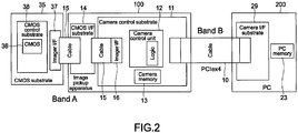
- Fig. 2 is a block diagram showing a hardware structure of the image pickup apparatus 100 and an interface therearound.
- the image pickup apparatus 100 includes a camera control substrate 11 and a CMOS I/F (interface) substrate 14.
- a cameral control unit 12 and a memory 13 are provided to the camera control substrate 11.
- the camera control unit 12 is structured as an FPGA (field programmable gate array), for example, and has a logic circuit therein.
- the memory (hereinafter, referred to as camera memory) 13 is a DRAM (dynamic random access memory) or the like, and functions as a buffer that stores an image read from a CMOS sensor 36 that is mounted on a CMOS control substrate 38.
- Imager I/Fs 16 and 37 in conformity with a predetermined communication standard are provided, respectively.
- the camera control substrate 11 and the CMOS substrate 35 are connected through the CMOS I/F substrate 14 and cables 15.
- the camera control unit 12 reads, through the cables 15, an image taken by the CMOS sensor 36 and stores the image in the camera memory 13. Further, under the control of the PC, the camera control unit 12 controls the operations of the CMOS sensor 36, the XYZ stage 31, and the flash light source 32.
- a control box dedicated to the XYZ stage may be provided separately from the camera control substrate 11.
- a memory (hereinafter, referred to as PC memory) 23 and a camera I/F substrate 29 for connection with the camera control substrate 11 are provided.
- the camera I/F substrate 29 of the PC 200 and the camera control substrate 11 of the image pickup apparatus 100 are connected with each other through the PCIe bus 10.
- the camera control unit transfers the image stored in the camera memory 13 to the PC memory 23 of the PC 200 via the PCIe bus 10.
- the PC memory 23 functions as a buffer for the image received.
- the transfer of the image between the camera memory 13 and the PC memory 23 is performed by a DMA (direct memory access).
- the camera memory 13, the PCIe bus 10, and the PC memory 23 are structured as an FIFO (first in, first out). That is, the camera memory 13 functions as a transmission FIFO buffer and the PC memory 23 functions as a reception FIFO buffer.
- a bandwidth (band B in Fig. 2 ) of the transmission using the PCIe bus 10 is larger than a bandwidth (band A in Fig. 2 ) of the transmission using the cables 15 between the CMOS substrate 35 and the camera control substrate 11.
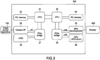
- Fig. 3 is a block diagram showing the hardware structure of the PC 200.
- the PC 200 includes CPUs 21 and 22 serving as a dual-core processor and the PC memory 23 and a PC memory 24 serving as the buffers corresponding to the CPUs 21 and 22, respectively.
- a buffer for storing an image received from the image pickup apparatus 100 is provided in each of the PC memories 23 and 24, a buffer for storing an image received from the image pickup apparatus 100 is provided.
- the buffer is formed as a redundant buffer such as a double buffer and a triple buffer.
- two GPUs 25 and 26 are connected through a PCIe bridge 28.
- the GPU 25 performs a developing process on an image received from the image pickup apparatus 100
- the GPU 26 performs an encoding process on the image to a JPEG format or the like (to be described later in detail).
- the camera I/F substrate 29 and an HDD 20 are connected through a PCIe bridge 27, for example.
- the image that has been received from the image pickup apparatus 100 and subjected to the developing process, the encoding process, and the like is stored in the HDD 20.
- various applications necessary for the developing process, the encoding process, and the like are also stored in the HDD 20.
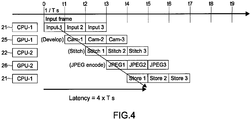
- Fig. 4 is a diagram showing a flow of the image processing.
- the PC 200 can pipeline, in addition to the developing process and the encoding process, an input process, a stitching process, a storing process, and the like and perform those processes with respect to the image received from the image pickup apparatus 100 side and stored in the PC memories 23 and 24.
- the stitching process refers to a process of connecting a plurality of images to be one image.
- the CPU 21 performs the input process on an image (frame) from the PC memories 23 and 24, for example.
- the GPU 25 performs the developing process on the input image, for example.
- the CPU 22 performs the stitching process on the image after the developing process.
- the GPU 26 performs the encoding (compressing) process on the image after the stitching process.
- the CPU 21 further performs the storing process of the image after the encoding process in the HDD 20, after the CPU 21 is released from the input process.
- the combinations of those various processes with the processors that perform the processes are not of course limited to the example shown in Fig. 4 .
- the PC 200 pipelines the five different processes with those parallel processors, for example, thereby making it possible to perform the image processing on the bulk raw data received via the PCIe bus 10 in real time as much as possible.
- a latency from the input to the storage of one image (frame) becomes significantly small, specifically, 4 ⁇ Ts, thanks to the pipeline process.
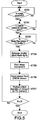
- Fig. 5 is a flowchart showing the image pickup process by the image pickup apparatus 100 and the PC 200.
- Fig. 6 is a block diagram showing a control system in the image pickup process.
- the CPU 21 or 22 (hereinafter, collectively referred to as CPU 21 for convenience) of the PC 200 judges whether the XYZ stage 31 is in a stop state, that is, the movement thereof is completed or not (Step 51).
- the CPU 21 judges whether the CMOS sensor 36 is in a standby state, that is, the CMOS sensor 36 is in an image-reading operation state to the camera memory 13 or not (Step 52).
- the CPU 21 judges whether the buffer of the PC memory 23 or 24 (hereinafter, collectively referred to as PC memory 23 for convenience) has a free space, that is, the volume of data in the buffer is less than a predetermined capacity or not (Step 53).
- the CPU 21 issues a shutter-on command to the camera control unit 12 and causes a shutter and the flash light source 32 to operate (Step 54).
- the camera control unit 12 starts the movement of the XYZ stage 31 for the next image pickup (Step 55). Further, the camera control unit 12 reads, from the CMOS sensor 36, the image taken in response to the shutter-on command and stores the image in the camera memory 13 (Step 56, (1) and (2) of Fig. 6 ).
- the camera control unit 12 reads the image stored in the camera memory 13 and performs a DMA transfer of the image to the PC memory 23 of the PC 200 (Step 57, (3) and (4) of Fig. 6 ).
- the image stored in the PC memory 23 is read, and the pipeline process described above is performed with the CPU 21, the GPU 25, and the like, and various applications ((5) of Fig. 6 ).
- the image pickup apparatus 100 and the PC 200 repeatedly perform the above-mentioned processes until a specified number of images are taken and stored in the PC 200.
- the movement of the XYZ stage 31 is completed during a time period when the image is read from the CMOS sensor 36 to the camera memory 13.
- a shutter timing is synchronous with the start of the movement of the XYZ stage 31.
- the completion of the image reading process from the CMOS sensor 36 to the camera memory 13 is also synchronous with the shutter timing.
- a latency time is reduced by a time period necessary for the movement of the XYZ stage 31, and therefore the image is taken and processed at a higher speed.
- the shutter is released only when the three conditions that the PC memory 23 has the free space, the CMOS sensor 36 is in the standby state, and the XYZ stage 31 is in the stop state are met. Further, by this control, the PC 200 can perform a back pressure process of temporarily stopping the shutter operation by the image pickup apparatus 100 in the case where the PC memory 23 does not have the free space.
- Fig. 7 is a timing chart showing an image pickup timing and the like in the image pickup process.
- Fig. 8 is a timing chart showing the case where the back pressure process is caused in the image pickup process.
- the camera control unit 12 monitors the state of the XYZ stage 31 and the CMOS sensor 36 and transmits, to the CPU 21 of the PC 200, notification signals (stage movement state notification command and CMOS sensor operation completion notification command) for making notifications of the stop of the XYZ stage 31 and the completion of the reading operation from the CMOS sensor 36 (standby state) as interrupt signals.
- the CPU 21 processes the notification signals as interrupt signals and monitors the capacity of the buffer of the PC memory 23. When the CPU 21 that a free space is generated (released) in the buffer, the CPU combines the conditions, to generate the shutter-on command. In synchronization with the issue of the shutter-on command, the processes of (1) to (5) of Fig. 6 are performed.
- the PC 200 is provided with an interrupt controller (not shown) for performing the interrupt process. By processing, as the interrupt signals, the conditions for the generation of the shutter-on command, the PC 200 can more flexibly arbitrate the conditions.
- a reading completion cycle from the CMOS sensor 36 is a critical path.
- a release of the buffer of the PC memory 23 is a critical path.
- the PC 200 can prevent the defect in the image data in a continuous transfer of the images through the PCIe bus 10.
- the camera memory 13 of the image pickup apparatus 100 and the PC memories 23 and 24 of the PC 200 are structured as the FIFO. Therefore, handshaking therebetween is unnecessary in performing the back pressure process.
- the CPUs 21 and 22 of the PC 200 just manages a queue of the FIFO, thereby allowing the back pressure process to be smoothly performed irrespective of the kind or state of a parallelism.
- the PC 200 processes and arbitrates the conditions for the generation of the shutter-on command as the interrupt signals.
- the arbitrating process may be performed on the image pickup apparatus 100 side.
- Fig. 9 is a timing chart showing an image pickup timing and the like in this case
- Fig. 10 is a timing chart showing the case where the back pressure process is generated in the example of Fig. 9 .
- an arbitration unit is provided to the image pickup apparatus 100.
- the arbitration unit may be implemented as hardware or software.
- the arbitration unit monitors the operation state of the XYZ stage 31 and the CMOS sensor 36 to generate a condition relating thereto, and receives a notification signal as to a condition of a free space state of the PC memory 23 from the PC 200. Further, the arbitration unit combines the conditions to generate the shutter-on command, thereby causing the camera control unit 12 to release the shutter.
- the arbitration unit suspends the issue of the shutter-on command until the arbitration unit receives the notification signal relating to the conditions of the free space state of the PC memory 23 from the PC 200, thereby performing the back pressure process.
- the arbitration unit on the image pickup apparatus 100 side arbitrates the conditions for the generation of the shutter-on command, the handshaking between the image pickup apparatus 100 and the PC 200 is reduced, and the overhead on the PC 200 side is reduced. Further, since the shutter-on command is issued on the image pickup apparatus 100 side without the PC 200, the latency until the shutter is released is reduced.
- the generation processes of the conditions on the image pickup apparatus 100 side and on the PC 200 side may be combined.
- the condition that is desirable to be generated on the PC 200 side may be generated by the PC 200
- the arbitration unit that combines the condition on the PC 200 side and the condition on the image pickup apparatus 100 side may be provided on the image pickup apparatus 100 side.
- the flexible arbitration by the PC 200 and the reduction in the latency are compatible with each other.
- the condition to be generated on the PC 200 side may be arbitrarily changed as appropriate.
- the image pickup apparatus 100 and the PC 200 are connected by the PCIe in the above example embodiment, but may be connected by another general-purpose high-speed interface such as USB 3.0 instead. That is, any communication channel may be used for the transfer of the image from the image pickup apparatus to the PC, as long as the communication channel has a larger bandwidth than that used for the reading of the image from the CMOS sensor and has the bidirectional reliability.
Landscapes
- Engineering & Computer Science (AREA)
- Multimedia (AREA)
- Physics & Mathematics (AREA)
- Computer Vision & Pattern Recognition (AREA)
- Chemical & Material Sciences (AREA)
- Analytical Chemistry (AREA)
- General Physics & Mathematics (AREA)
- Optics & Photonics (AREA)
- Microscoopes, Condenser (AREA)
- Studio Devices (AREA)
- Investigating Or Analysing Biological Materials (AREA)
Applications Claiming Priority (1)
| Application Number | Priority Date | Filing Date | Title |
|---|---|---|---|
| JP2009285154A JP5573145B2 (ja) | 2009-12-16 | 2009-12-16 | 画像処理システム、画像処理装置、画像処理方法及びプログラム |
Publications (2)
| Publication Number | Publication Date |
|---|---|
| EP2341385A1 EP2341385A1 (en) | 2011-07-06 |
| EP2341385B1 true EP2341385B1 (en) | 2019-07-17 |
Family
ID=43824563
Family Applications (1)
| Application Number | Title | Priority Date | Filing Date |
|---|---|---|---|
| EP10015440.0A Not-in-force EP2341385B1 (en) | 2009-12-16 | 2010-12-08 | Image processing system, image processing apparatus, image pickup apparatus, method, and computer-readable medium |
Country Status (5)
| Country | Link |
|---|---|
| US (1) | US20110141261A1 (ja) |
| EP (1) | EP2341385B1 (ja) |
| JP (1) | JP5573145B2 (ja) |
| KR (1) | KR20110068863A (ja) |
| CN (1) | CN102103737B (ja) |
Families Citing this family (5)
| Publication number | Priority date | Publication date | Assignee | Title |
|---|---|---|---|---|
| JP6165468B2 (ja) * | 2012-03-05 | 2017-07-19 | 東芝メディカルシステムズ株式会社 | 医用画像処理システム |
| JP6865010B2 (ja) * | 2016-10-19 | 2021-04-28 | オリンパス株式会社 | 顕微鏡システムおよび標本観察方法 |
| JP7013677B2 (ja) * | 2017-05-01 | 2022-02-01 | ソニーグループ株式会社 | 医用画像処理装置、医用画像処理装置の作動方法、及び、内視鏡システム |
| JP2021193762A (ja) * | 2018-09-28 | 2021-12-23 | ソニーグループ株式会社 | 受信装置、および受信方法、並びに、画像処理システム |
| CN110737253B (zh) * | 2019-10-15 | 2021-09-07 | 浙江隐齿丽医学技术有限公司 | 具有自动适配功能的备膜装置、自动适配系统及方法 |
Family Cites Families (21)
| Publication number | Priority date | Publication date | Assignee | Title |
|---|---|---|---|---|
| ATE212042T1 (de) * | 1990-03-06 | 2002-02-15 | Mitsui Chemicals Inc | Statistische cycloolefincopolymere und verfahren zu ihrer herstellung |
| US6645701B1 (en) * | 1995-11-22 | 2003-11-11 | Nikon Corporation | Exposure method and exposure apparatus |
| US6396941B1 (en) * | 1996-08-23 | 2002-05-28 | Bacus Research Laboratories, Inc. | Method and apparatus for internet, intranet, and local viewing of virtual microscope slides |
| US6031930A (en) * | 1996-08-23 | 2000-02-29 | Bacus Research Laboratories, Inc. | Method and apparatus for testing a progression of neoplasia including cancer chemoprevention testing |
| US6272235B1 (en) | 1997-03-03 | 2001-08-07 | Bacus Research Laboratories, Inc. | Method and apparatus for creating a virtual microscope slide |
| US6404906B2 (en) * | 1997-03-03 | 2002-06-11 | Bacus Research Laboratories,Inc. | Method and apparatus for acquiring and reconstructing magnified specimen images from a computer-controlled microscope |
| US6466231B1 (en) * | 1998-08-07 | 2002-10-15 | Hewlett-Packard Company | Appliance and method of using same for capturing images |
| US6724419B1 (en) * | 1999-08-13 | 2004-04-20 | Universal Imaging Corporation | System and method for acquiring images at maximum acquisition rate while asynchronously sequencing microscope devices |
| US6711283B1 (en) * | 2000-05-03 | 2004-03-23 | Aperio Technologies, Inc. | Fully automatic rapid microscope slide scanner |
| US7155049B2 (en) * | 2001-01-11 | 2006-12-26 | Trestle Acquisition Corp. | System for creating microscopic digital montage images |
| JP4912543B2 (ja) * | 2001-07-09 | 2012-04-11 | オリンパス株式会社 | 顕微鏡の画像撮影装置、画像撮影方法 |
| JP2003110925A (ja) * | 2001-09-28 | 2003-04-11 | Canon Inc | 電子カメラ、その制御方法および制御プログラム |
| JP3973408B2 (ja) * | 2001-11-22 | 2007-09-12 | 富士フイルム株式会社 | ディジタル・ムービ・カメラおよびその動作制御方法 |
| TW200305927A (en) * | 2002-03-22 | 2003-11-01 | Nippon Kogaku Kk | Exposure apparatus, exposure method and manufacturing method of device |
| JP2004309719A (ja) * | 2003-04-04 | 2004-11-04 | Olympus Corp | 顕微鏡システム、顕微鏡システムの制御方法、及び制御プログラム |
| JP2005328201A (ja) * | 2004-05-12 | 2005-11-24 | Olympus Corp | 顕微鏡デジタルカメラ |
| JP4693650B2 (ja) * | 2006-02-17 | 2011-06-01 | キヤノン株式会社 | 撮像装置及びその制御方法及びプログラム |
| JP2008040008A (ja) * | 2006-08-03 | 2008-02-21 | Olympus Imaging Corp | デジタルカメラ |
| US7978239B2 (en) * | 2007-03-01 | 2011-07-12 | Eastman Kodak Company | Digital camera using multiple image sensors to provide improved temporal sampling |
| US8520250B2 (en) * | 2007-09-12 | 2013-08-27 | Ricoh Company, Ltd. | Image reading apparatus and method, and computer-readable recording medium |
| JP5075017B2 (ja) | 2008-05-29 | 2012-11-14 | 日本電信電話株式会社 | 末梢神経型柔軟神経電極およびその作製方法 |
-
2009
- 2009-12-16 JP JP2009285154A patent/JP5573145B2/ja not_active Expired - Fee Related
-
2010
- 2010-11-05 US US12/940,560 patent/US20110141261A1/en not_active Abandoned
- 2010-12-08 KR KR1020100124794A patent/KR20110068863A/ko not_active Application Discontinuation
- 2010-12-08 EP EP10015440.0A patent/EP2341385B1/en not_active Not-in-force
- 2010-12-09 CN CN201010581530.1A patent/CN102103737B/zh not_active Expired - Fee Related
Non-Patent Citations (1)
| Title |
|---|
| None * |
Also Published As
| Publication number | Publication date |
|---|---|
| JP5573145B2 (ja) | 2014-08-20 |
| KR20110068863A (ko) | 2011-06-22 |
| JP2011130074A (ja) | 2011-06-30 |
| EP2341385A1 (en) | 2011-07-06 |
| CN102103737A (zh) | 2011-06-22 |
| CN102103737B (zh) | 2016-04-20 |
| US20110141261A1 (en) | 2011-06-16 |
Similar Documents
| Publication | Publication Date | Title |
|---|---|---|
| EP2341385B1 (en) | Image processing system, image processing apparatus, image pickup apparatus, method, and computer-readable medium | |
| TWI285499B (en) | Video camera sharing | |
| US20220000340A1 (en) | Signal processing device and medical observation system | |
| US20130250091A1 (en) | Image processing apparatus, image processing system, image processing method, and program | |
| US11302439B2 (en) | Medical image processing apparatus, medical image processing method, and computing device | |
| US10905310B2 (en) | Signal processing device and medical observation system | |
| US20190057053A1 (en) | Data transfer device, image processing device, and imaging device | |
| US20100135644A1 (en) | Photographing apparatus and method of controlling the same | |
| US20190324646A1 (en) | Memory access device, image-processing device, and imaging device | |
| JP7066454B2 (ja) | 医療用観察装置 | |
| US20230100302A1 (en) | Medical information control system, signal processing device, and medical information control method | |
| WO2019043822A1 (ja) | メモリアクセス装置、画像処理装置、および撮像装置 | |
| US11314664B2 (en) | Memory access device, image processing device and imaging device | |
| US11303846B2 (en) | Imaging system and method capable of processing multiple imaging formats | |
| US11381774B2 (en) | Microscope system and method for operating a microscope system | |
| CN209895383U (zh) | 一种数字图像大数据的高速传输装置 | |
| JP2018182551A (ja) | 撮像装置 | |
| WO2016203996A1 (ja) | データ転送装置およびデータ転送方法 | |
| US20240037808A1 (en) | Systems and methods for real-time processing of medical imaging data utilizing an external processing device | |
| KR100978421B1 (ko) | 고속데이터 전송이 가능한 디지털 현미경 | |
| JP2017220180A (ja) | 画像処理システム、画像処理装置、および画像処理方法 | |
| JP6298667B2 (ja) | 撮像表示装置、撮像表示装置の制御方法及びそのプログラム | |
| JP2010147662A (ja) | 電子カメラシステムおよびカメラユニット |
Legal Events
| Date | Code | Title | Description |
|---|---|---|---|
| PUAI | Public reference made under article 153(3) epc to a published international application that has entered the european phase |
Free format text: ORIGINAL CODE: 0009012 |
|
| 17P | Request for examination filed |
Effective date: 20101208 |
|
| AK | Designated contracting states |
Kind code of ref document: A1 Designated state(s): AL AT BE BG CH CY CZ DE DK EE ES FI FR GB GR HR HU IE IS IT LI LT LU LV MC MK MT NL NO PL PT RO RS SE SI SK SM TR |
|
| AX | Request for extension of the european patent |
Extension state: BA ME |
|
| STAA | Information on the status of an ep patent application or granted ep patent |
Free format text: STATUS: EXAMINATION IS IN PROGRESS |
|
| 17Q | First examination report despatched |
Effective date: 20161121 |
|
| GRAP | Despatch of communication of intention to grant a patent |
Free format text: ORIGINAL CODE: EPIDOSNIGR1 |
|
| STAA | Information on the status of an ep patent application or granted ep patent |
Free format text: STATUS: GRANT OF PATENT IS INTENDED |
|
| INTG | Intention to grant announced |
Effective date: 20190201 |
|
| GRAS | Grant fee paid |
Free format text: ORIGINAL CODE: EPIDOSNIGR3 |
|
| GRAA | (expected) grant |
Free format text: ORIGINAL CODE: 0009210 |
|
| STAA | Information on the status of an ep patent application or granted ep patent |
Free format text: STATUS: THE PATENT HAS BEEN GRANTED |
|
| AK | Designated contracting states |
Kind code of ref document: B1 Designated state(s): AL AT BE BG CH CY CZ DE DK EE ES FI FR GB GR HR HU IE IS IT LI LT LU LV MC MK MT NL NO PL PT RO RS SE SI SK SM TR |
|
| REG | Reference to a national code |
Ref country code: GB Ref legal event code: FG4D |
|
| REG | Reference to a national code |
Ref country code: CH Ref legal event code: EP |
|
| REG | Reference to a national code |
Ref country code: IE Ref legal event code: FG4D |
|
| REG | Reference to a national code |
Ref country code: DE Ref legal event code: R096 Ref document number: 602010060018 Country of ref document: DE |
|
| REG | Reference to a national code |
Ref country code: AT Ref legal event code: REF Ref document number: 1156381 Country of ref document: AT Kind code of ref document: T Effective date: 20190815 |
|
| REG | Reference to a national code |
Ref country code: NL Ref legal event code: MP Effective date: 20190717 |
|
| REG | Reference to a national code |
Ref country code: LT Ref legal event code: MG4D |
|
| REG | Reference to a national code |
Ref country code: AT Ref legal event code: MK05 Ref document number: 1156381 Country of ref document: AT Kind code of ref document: T Effective date: 20190717 |
|
| PG25 | Lapsed in a contracting state [announced via postgrant information from national office to epo] |
Ref country code: BG Free format text: LAPSE BECAUSE OF FAILURE TO SUBMIT A TRANSLATION OF THE DESCRIPTION OR TO PAY THE FEE WITHIN THE PRESCRIBED TIME-LIMIT Effective date: 20191017 Ref country code: NL Free format text: LAPSE BECAUSE OF FAILURE TO SUBMIT A TRANSLATION OF THE DESCRIPTION OR TO PAY THE FEE WITHIN THE PRESCRIBED TIME-LIMIT Effective date: 20190717 Ref country code: AT Free format text: LAPSE BECAUSE OF FAILURE TO SUBMIT A TRANSLATION OF THE DESCRIPTION OR TO PAY THE FEE WITHIN THE PRESCRIBED TIME-LIMIT Effective date: 20190717 Ref country code: PT Free format text: LAPSE BECAUSE OF FAILURE TO SUBMIT A TRANSLATION OF THE DESCRIPTION OR TO PAY THE FEE WITHIN THE PRESCRIBED TIME-LIMIT Effective date: 20191118 Ref country code: HR Free format text: LAPSE BECAUSE OF FAILURE TO SUBMIT A TRANSLATION OF THE DESCRIPTION OR TO PAY THE FEE WITHIN THE PRESCRIBED TIME-LIMIT Effective date: 20190717 Ref country code: LT Free format text: LAPSE BECAUSE OF FAILURE TO SUBMIT A TRANSLATION OF THE DESCRIPTION OR TO PAY THE FEE WITHIN THE PRESCRIBED TIME-LIMIT Effective date: 20190717 Ref country code: NO Free format text: LAPSE BECAUSE OF FAILURE TO SUBMIT A TRANSLATION OF THE DESCRIPTION OR TO PAY THE FEE WITHIN THE PRESCRIBED TIME-LIMIT Effective date: 20191017 Ref country code: FI Free format text: LAPSE BECAUSE OF FAILURE TO SUBMIT A TRANSLATION OF THE DESCRIPTION OR TO PAY THE FEE WITHIN THE PRESCRIBED TIME-LIMIT Effective date: 20190717 Ref country code: SE Free format text: LAPSE BECAUSE OF FAILURE TO SUBMIT A TRANSLATION OF THE DESCRIPTION OR TO PAY THE FEE WITHIN THE PRESCRIBED TIME-LIMIT Effective date: 20190717 |
|
| PG25 | Lapsed in a contracting state [announced via postgrant information from national office to epo] |
Ref country code: IS Free format text: LAPSE BECAUSE OF FAILURE TO SUBMIT A TRANSLATION OF THE DESCRIPTION OR TO PAY THE FEE WITHIN THE PRESCRIBED TIME-LIMIT Effective date: 20191117 Ref country code: LV Free format text: LAPSE BECAUSE OF FAILURE TO SUBMIT A TRANSLATION OF THE DESCRIPTION OR TO PAY THE FEE WITHIN THE PRESCRIBED TIME-LIMIT Effective date: 20190717 Ref country code: GR Free format text: LAPSE BECAUSE OF FAILURE TO SUBMIT A TRANSLATION OF THE DESCRIPTION OR TO PAY THE FEE WITHIN THE PRESCRIBED TIME-LIMIT Effective date: 20191018 Ref country code: RS Free format text: LAPSE BECAUSE OF FAILURE TO SUBMIT A TRANSLATION OF THE DESCRIPTION OR TO PAY THE FEE WITHIN THE PRESCRIBED TIME-LIMIT Effective date: 20190717 Ref country code: ES Free format text: LAPSE BECAUSE OF FAILURE TO SUBMIT A TRANSLATION OF THE DESCRIPTION OR TO PAY THE FEE WITHIN THE PRESCRIBED TIME-LIMIT Effective date: 20190717 Ref country code: AL Free format text: LAPSE BECAUSE OF FAILURE TO SUBMIT A TRANSLATION OF THE DESCRIPTION OR TO PAY THE FEE WITHIN THE PRESCRIBED TIME-LIMIT Effective date: 20190717 |
|
| PG25 | Lapsed in a contracting state [announced via postgrant information from national office to epo] |
Ref country code: TR Free format text: LAPSE BECAUSE OF FAILURE TO SUBMIT A TRANSLATION OF THE DESCRIPTION OR TO PAY THE FEE WITHIN THE PRESCRIBED TIME-LIMIT Effective date: 20190717 |
|
| PG25 | Lapsed in a contracting state [announced via postgrant information from national office to epo] |
Ref country code: RO Free format text: LAPSE BECAUSE OF FAILURE TO SUBMIT A TRANSLATION OF THE DESCRIPTION OR TO PAY THE FEE WITHIN THE PRESCRIBED TIME-LIMIT Effective date: 20190717 Ref country code: IT Free format text: LAPSE BECAUSE OF FAILURE TO SUBMIT A TRANSLATION OF THE DESCRIPTION OR TO PAY THE FEE WITHIN THE PRESCRIBED TIME-LIMIT Effective date: 20190717 Ref country code: EE Free format text: LAPSE BECAUSE OF FAILURE TO SUBMIT A TRANSLATION OF THE DESCRIPTION OR TO PAY THE FEE WITHIN THE PRESCRIBED TIME-LIMIT Effective date: 20190717 Ref country code: DK Free format text: LAPSE BECAUSE OF FAILURE TO SUBMIT A TRANSLATION OF THE DESCRIPTION OR TO PAY THE FEE WITHIN THE PRESCRIBED TIME-LIMIT Effective date: 20190717 Ref country code: PL Free format text: LAPSE BECAUSE OF FAILURE TO SUBMIT A TRANSLATION OF THE DESCRIPTION OR TO PAY THE FEE WITHIN THE PRESCRIBED TIME-LIMIT Effective date: 20190717 |
|
| PG25 | Lapsed in a contracting state [announced via postgrant information from national office to epo] |
Ref country code: SK Free format text: LAPSE BECAUSE OF FAILURE TO SUBMIT A TRANSLATION OF THE DESCRIPTION OR TO PAY THE FEE WITHIN THE PRESCRIBED TIME-LIMIT Effective date: 20190717 Ref country code: CZ Free format text: LAPSE BECAUSE OF FAILURE TO SUBMIT A TRANSLATION OF THE DESCRIPTION OR TO PAY THE FEE WITHIN THE PRESCRIBED TIME-LIMIT Effective date: 20190717 Ref country code: IS Free format text: LAPSE BECAUSE OF FAILURE TO SUBMIT A TRANSLATION OF THE DESCRIPTION OR TO PAY THE FEE WITHIN THE PRESCRIBED TIME-LIMIT Effective date: 20200224 Ref country code: SM Free format text: LAPSE BECAUSE OF FAILURE TO SUBMIT A TRANSLATION OF THE DESCRIPTION OR TO PAY THE FEE WITHIN THE PRESCRIBED TIME-LIMIT Effective date: 20190717 |
|
| REG | Reference to a national code |
Ref country code: DE Ref legal event code: R097 Ref document number: 602010060018 Country of ref document: DE |
|
| PLBE | No opposition filed within time limit |
Free format text: ORIGINAL CODE: 0009261 |
|
| STAA | Information on the status of an ep patent application or granted ep patent |
Free format text: STATUS: NO OPPOSITION FILED WITHIN TIME LIMIT |
|
| PG2D | Information on lapse in contracting state deleted |
Ref country code: IS |
|
| REG | Reference to a national code |
Ref country code: CH Ref legal event code: PL |
|
| 26N | No opposition filed |
Effective date: 20200603 |
|
| REG | Reference to a national code |
Ref country code: BE Ref legal event code: MM Effective date: 20191231 |
|
| PG25 | Lapsed in a contracting state [announced via postgrant information from national office to epo] |
Ref country code: MC Free format text: LAPSE BECAUSE OF FAILURE TO SUBMIT A TRANSLATION OF THE DESCRIPTION OR TO PAY THE FEE WITHIN THE PRESCRIBED TIME-LIMIT Effective date: 20190717 Ref country code: SI Free format text: LAPSE BECAUSE OF FAILURE TO SUBMIT A TRANSLATION OF THE DESCRIPTION OR TO PAY THE FEE WITHIN THE PRESCRIBED TIME-LIMIT Effective date: 20190717 |
|
| PG25 | Lapsed in a contracting state [announced via postgrant information from national office to epo] |
Ref country code: LU Free format text: LAPSE BECAUSE OF NON-PAYMENT OF DUE FEES Effective date: 20191208 Ref country code: IE Free format text: LAPSE BECAUSE OF NON-PAYMENT OF DUE FEES Effective date: 20191208 |
|
| PG25 | Lapsed in a contracting state [announced via postgrant information from national office to epo] |
Ref country code: LI Free format text: LAPSE BECAUSE OF NON-PAYMENT OF DUE FEES Effective date: 20191231 Ref country code: BE Free format text: LAPSE BECAUSE OF NON-PAYMENT OF DUE FEES Effective date: 20191231 Ref country code: CH Free format text: LAPSE BECAUSE OF NON-PAYMENT OF DUE FEES Effective date: 20191231 |
|
| PG25 | Lapsed in a contracting state [announced via postgrant information from national office to epo] |
Ref country code: CY Free format text: LAPSE BECAUSE OF FAILURE TO SUBMIT A TRANSLATION OF THE DESCRIPTION OR TO PAY THE FEE WITHIN THE PRESCRIBED TIME-LIMIT Effective date: 20190717 |
|
| PG25 | Lapsed in a contracting state [announced via postgrant information from national office to epo] |
Ref country code: HU Free format text: LAPSE BECAUSE OF FAILURE TO SUBMIT A TRANSLATION OF THE DESCRIPTION OR TO PAY THE FEE WITHIN THE PRESCRIBED TIME-LIMIT; INVALID AB INITIO Effective date: 20101208 Ref country code: MT Free format text: LAPSE BECAUSE OF FAILURE TO SUBMIT A TRANSLATION OF THE DESCRIPTION OR TO PAY THE FEE WITHIN THE PRESCRIBED TIME-LIMIT Effective date: 20190717 |
|
| PGFP | Annual fee paid to national office [announced via postgrant information from national office to epo] |
Ref country code: DE Payment date: 20211117 Year of fee payment: 12 Ref country code: FR Payment date: 20211117 Year of fee payment: 12 Ref country code: GB Payment date: 20211118 Year of fee payment: 12 |
|
| PG25 | Lapsed in a contracting state [announced via postgrant information from national office to epo] |
Ref country code: MK Free format text: LAPSE BECAUSE OF FAILURE TO SUBMIT A TRANSLATION OF THE DESCRIPTION OR TO PAY THE FEE WITHIN THE PRESCRIBED TIME-LIMIT Effective date: 20190717 |
|
| REG | Reference to a national code |
Ref country code: DE Ref legal event code: R119 Ref document number: 602010060018 Country of ref document: DE |
|
| GBPC | Gb: european patent ceased through non-payment of renewal fee |
Effective date: 20221208 |
|
| PG25 | Lapsed in a contracting state [announced via postgrant information from national office to epo] |
Ref country code: GB Free format text: LAPSE BECAUSE OF NON-PAYMENT OF DUE FEES Effective date: 20221208 Ref country code: DE Free format text: LAPSE BECAUSE OF NON-PAYMENT OF DUE FEES Effective date: 20230701 |
|
| PG25 | Lapsed in a contracting state [announced via postgrant information from national office to epo] |
Ref country code: FR Free format text: LAPSE BECAUSE OF NON-PAYMENT OF DUE FEES Effective date: 20221231 |