EP2340925B1 - Procédé de fabrication générative d'un objet tridimensionnel doté d'une amenée de chaleur en continu - Google Patents
Procédé de fabrication générative d'un objet tridimensionnel doté d'une amenée de chaleur en continu Download PDFInfo
- Publication number
- EP2340925B1 EP2340925B1 EP11150079A EP11150079A EP2340925B1 EP 2340925 B1 EP2340925 B1 EP 2340925B1 EP 11150079 A EP11150079 A EP 11150079A EP 11150079 A EP11150079 A EP 11150079A EP 2340925 B1 EP2340925 B1 EP 2340925B1
- Authority
- EP
- European Patent Office
- Prior art keywords
- heating device
- heat
- building field
- process according
- frame
- Prior art date
- Legal status (The legal status is an assumption and is not a legal conclusion. Google has not performed a legal analysis and makes no representation as to the accuracy of the status listed.)
- Not-in-force
Links
Images


Classifications
-
- B—PERFORMING OPERATIONS; TRANSPORTING
- B29—WORKING OF PLASTICS; WORKING OF SUBSTANCES IN A PLASTIC STATE IN GENERAL
- B29C—SHAPING OR JOINING OF PLASTICS; SHAPING OF MATERIAL IN A PLASTIC STATE, NOT OTHERWISE PROVIDED FOR; AFTER-TREATMENT OF THE SHAPED PRODUCTS, e.g. REPAIRING
- B29C35/00—Heating, cooling or curing, e.g. crosslinking or vulcanising; Apparatus therefor
- B29C35/007—Tempering units for temperature control of moulds or cores, e.g. comprising heat exchangers, controlled valves, temperature-controlled circuits for fluids
-
- B—PERFORMING OPERATIONS; TRANSPORTING
- B22—CASTING; POWDER METALLURGY
- B22F—WORKING METALLIC POWDER; MANUFACTURE OF ARTICLES FROM METALLIC POWDER; MAKING METALLIC POWDER; APPARATUS OR DEVICES SPECIALLY ADAPTED FOR METALLIC POWDER
- B22F10/00—Additive manufacturing of workpieces or articles from metallic powder
- B22F10/20—Direct sintering or melting
- B22F10/28—Powder bed fusion, e.g. selective laser melting [SLM] or electron beam melting [EBM]
-
- B—PERFORMING OPERATIONS; TRANSPORTING
- B22—CASTING; POWDER METALLURGY
- B22F—WORKING METALLIC POWDER; MANUFACTURE OF ARTICLES FROM METALLIC POWDER; MAKING METALLIC POWDER; APPARATUS OR DEVICES SPECIALLY ADAPTED FOR METALLIC POWDER
- B22F12/00—Apparatus or devices specially adapted for additive manufacturing; Auxiliary means for additive manufacturing; Combinations of additive manufacturing apparatus or devices with other processing apparatus or devices
- B22F12/10—Auxiliary heating means
- B22F12/13—Auxiliary heating means to preheat the material
-
- B—PERFORMING OPERATIONS; TRANSPORTING
- B22—CASTING; POWDER METALLURGY
- B22F—WORKING METALLIC POWDER; MANUFACTURE OF ARTICLES FROM METALLIC POWDER; MAKING METALLIC POWDER; APPARATUS OR DEVICES SPECIALLY ADAPTED FOR METALLIC POWDER
- B22F12/00—Apparatus or devices specially adapted for additive manufacturing; Auxiliary means for additive manufacturing; Combinations of additive manufacturing apparatus or devices with other processing apparatus or devices
- B22F12/10—Auxiliary heating means
- B22F12/17—Auxiliary heating means to heat the build chamber or platform
-
- B—PERFORMING OPERATIONS; TRANSPORTING
- B29—WORKING OF PLASTICS; WORKING OF SUBSTANCES IN A PLASTIC STATE IN GENERAL
- B29C—SHAPING OR JOINING OF PLASTICS; SHAPING OF MATERIAL IN A PLASTIC STATE, NOT OTHERWISE PROVIDED FOR; AFTER-TREATMENT OF THE SHAPED PRODUCTS, e.g. REPAIRING
- B29C64/00—Additive manufacturing, i.e. manufacturing of three-dimensional [3D] objects by additive deposition, additive agglomeration or additive layering, e.g. by 3D printing, stereolithography or selective laser sintering
- B29C64/10—Processes of additive manufacturing
- B29C64/141—Processes of additive manufacturing using only solid materials
- B29C64/153—Processes of additive manufacturing using only solid materials using layers of powder being selectively joined, e.g. by selective laser sintering or melting
-
- B—PERFORMING OPERATIONS; TRANSPORTING
- B33—ADDITIVE MANUFACTURING TECHNOLOGY
- B33Y—ADDITIVE MANUFACTURING, i.e. MANUFACTURING OF THREE-DIMENSIONAL [3-D] OBJECTS BY ADDITIVE DEPOSITION, ADDITIVE AGGLOMERATION OR ADDITIVE LAYERING, e.g. BY 3-D PRINTING, STEREOLITHOGRAPHY OR SELECTIVE LASER SINTERING
- B33Y30/00—Apparatus for additive manufacturing; Details thereof or accessories therefor
-
- B—PERFORMING OPERATIONS; TRANSPORTING
- B22—CASTING; POWDER METALLURGY
- B22F—WORKING METALLIC POWDER; MANUFACTURE OF ARTICLES FROM METALLIC POWDER; MAKING METALLIC POWDER; APPARATUS OR DEVICES SPECIALLY ADAPTED FOR METALLIC POWDER
- B22F12/00—Apparatus or devices specially adapted for additive manufacturing; Auxiliary means for additive manufacturing; Combinations of additive manufacturing apparatus or devices with other processing apparatus or devices
- B22F12/22—Driving means
- B22F12/222—Driving means for motion along a direction orthogonal to the plane of a layer
-
- B—PERFORMING OPERATIONS; TRANSPORTING
- B22—CASTING; POWDER METALLURGY
- B22F—WORKING METALLIC POWDER; MANUFACTURE OF ARTICLES FROM METALLIC POWDER; MAKING METALLIC POWDER; APPARATUS OR DEVICES SPECIALLY ADAPTED FOR METALLIC POWDER
- B22F12/00—Apparatus or devices specially adapted for additive manufacturing; Auxiliary means for additive manufacturing; Combinations of additive manufacturing apparatus or devices with other processing apparatus or devices
- B22F12/90—Means for process control, e.g. cameras or sensors
-
- B—PERFORMING OPERATIONS; TRANSPORTING
- B22—CASTING; POWDER METALLURGY
- B22F—WORKING METALLIC POWDER; MANUFACTURE OF ARTICLES FROM METALLIC POWDER; MAKING METALLIC POWDER; APPARATUS OR DEVICES SPECIALLY ADAPTED FOR METALLIC POWDER
- B22F2999/00—Aspects linked to processes or compositions used in powder metallurgy
-
- Y—GENERAL TAGGING OF NEW TECHNOLOGICAL DEVELOPMENTS; GENERAL TAGGING OF CROSS-SECTIONAL TECHNOLOGIES SPANNING OVER SEVERAL SECTIONS OF THE IPC; TECHNICAL SUBJECTS COVERED BY FORMER USPC CROSS-REFERENCE ART COLLECTIONS [XRACs] AND DIGESTS
- Y02—TECHNOLOGIES OR APPLICATIONS FOR MITIGATION OR ADAPTATION AGAINST CLIMATE CHANGE
- Y02P—CLIMATE CHANGE MITIGATION TECHNOLOGIES IN THE PRODUCTION OR PROCESSING OF GOODS
- Y02P10/00—Technologies related to metal processing
- Y02P10/25—Process efficiency
Definitions
- the present invention relates to a method of generatively producing a three-dimensional object.
- EP 0 764 079 B1 describes a known laser sintering device, with a container which encloses a construction field with its upper edge; a carrier, which is arranged in the container and is vertically movable by a lifting mechanism at least below the construction field; an irradiation device that generates an energy beam that is focused by a deflector to any points in the construction field to selectively sinter or melt powder material located in the construction field; a coater for applying a layer of a powder material to the support or a previously applied layer of the powder material.
- the laser sintering apparatus has a heater which serves to heat a powder layer applied with a coater to a pre-temperature required for sintering by means of the laser beam.
- the heater in EP 0 764 079 B1 has a sensor in shape a pyrometer, which is mounted at a predetermined location above the powder bed or the construction field.
- the temperature signals of the pyrometer are used as the actual value for a PID or PI control.
- US 6,930,278 B1 discloses, according to the preamble of claim 1, a method for generatively producing a three-dimensional object, comprising a device comprising: a frame whose upper portion encloses a construction field; a carrier, which is arranged in the frame and is vertically movable by a lifting mechanism at least below the construction field; a device for generating energy-sensitive radiation which selectively impinges on any punts in the construction field to selectively sinter or melt powder material located in the construction field; a coater for applying a layer of a powder material to the support or a previously applied layer of the powder material; a housing in which at least the frame and the carrier are arranged and which encloses a construction space; and a heating device that continuously supplies heat to at least the construction field environment or the installation space thereabove; wherein the heating device is provided in addition to a further heating device for heating the construction field.
- the heating capacity of all heaters is regulated by means of a common setpoint.
- the continuous heat loss is compensated by the continuous supply of heat, so that heat losses at the edge of the construction field can be minimized and a better temperature distribution is made possible up to the edge region.
- This increases the process-reliable effective construction field, and it can be achieved a homogeneous heat and temperature distribution over the entire construction field.
- the Fig. 1 shows a schematic view of an apparatus for producing a three-dimensional object 3 according to a first embodiment, which is exemplified as a laser sintering device.
- the laser sintering device has an upwardly open frame 1 with a vertically movable therein carrier 5, which is the produced three-dimensional Object 3 carries.
- the frame 1 encloses at its upper portion 2 a construction field 6.
- the frame 1 and the carrier 5 form an exchangeable removable frame, which can be removed from the laser sintering device.
- the carrier 5 is connected to a lifting mechanism 4, which moves it at least below the plane of the construction field 6 in the vertical direction so that the top of each powder layer to be solidified in the plane of the construction field 6.
- the plane in which the upper edge of the upper section 2 lies is considered here.
- a coater 10 for applying a layer of powder material 11 is provided.
- powder material 11 all laser-sinterable powders can be used, for example laser-sinterable polymers such as polyaryletherketones, polyarylethersulfanes, polyamides, polyesters, polyethers, polyolefins, polystyrenes, polyphenylene sulfides, polyvinylidene fluorides, polyphenylene oxides, polyimides, their copolymers and blends which include at least one of the preceding polymers however, the choice is not limited to the above polymers and copolymers.
- laser-sinterable polymers such as polyaryletherketones, polyarylethersulfanes, polyamides, polyesters, polyethers, polyolefins, polystyrenes, polyphenylene sulfides, polyvinylidene fluorides, polyphenylene oxides, polyimides, their copolymers and blends which include at least one
- Particularly suitable polyaryletherketones can be selected from the group consisting of polyetheretherketone (PEEK), polyetherketone ketone (PEKK), polyetherketone (PEK), polyetheretherketone ketone (PEEKK) and polyetherketone ether ketone ketone (PEKEKK) and polyetheretheretherketone (PEEEK) and copolymers thereof, in particular with polyorganyl ether sulfones and blends thereof which are at least include one of the aforementioned polymers.
- Particularly suitable polyamide polymers or copolymers and their blends can be selected from the group consisting of polamid 6 / 6T, polyamide elastomers such as polyether block amides such as PEBAX-based materials, Polyamide 6, polyamide 66, polyamide 11, polyamide 12, polyamide 612, polyamide 610, polyamide 1010, polyamide 1212, polyamide PA6T / 66, PA4T / 46, and copolymers including at least one of the foregoing polymers.
- Suitable polyester polymers or copolymers can be selected from polyalkylene terephthalates (eg, PET, PBT) and their copolymers.
- Suitable polyolefin polymers or copolymers can be selected from the group consisting of polyethylene and polypropylene.
- Suitable polystyrene polymers or copolymers can be selected from the group consisting of syndiotactic and isotactic polystyrenes.
- polymer composite powders containing fillers and / or additives besides the corresponding polymer, copolymer or blend can be used.
- fillers include, for example, fibers such as carbon or glass fibers and carbon nanotubes, fillers with a low aspect ratio such as glass beads or Alugries, mineral fillers such as titanium dioxide.
- Additives include, but are not limited to, processing aids such as Aerosil series flow aids (eg, Aerosil 200), functional additives such as heat stabilizers, oxidation stabilizers, color pigments (eg, graphite and carbon black), and flame retardants (eg, organophosphates, polybrominated hydrocarbons).
- processing aids such as Aerosil series flow aids (eg, Aerosil 200)
- functional additives such as heat stabilizers, oxidation stabilizers, color pigments (eg, graphite and carbon black), and flame retardants (eg, organophosphates, polybrominated hydrocarbons).
- heat stabilizers eg, Aerosil 200
- oxidation stabilizers eg, color pigments (eg, graphite and carbon black)
- flame retardants eg, organophosphates, polybrominated hydrocarbons.
- metals, ceramics, foundry sand, and composite materials may also be used. Any metal and its alloys
- the coater 10 is moved over the building field 6 at a predetermined height, so that the layer of the powder material 11 with a defined height above the support 5 or over the last solidified layer lies.
- the apparatus further comprises an irradiation device in the form of a laser 7, which generates a laser beam 8, 8 ', which is focused by a deflector 9 to any points in the construction field 6.
- the laser beam 8, 8 ' can selectively solidify the powder material 11 at the locations corresponding to the cross section of the object 3 to be produced.
- the reference numeral 100 denotes a housing in which the frame 1, the carrier 5 and the coater 10 are arranged.
- the housing 100 has an inlet for the laser beam 8, 8 'in the upper area.
- the housing 100 is gas-tight, so that a protective gas can be introduced.
- the interior of the housing 100 is referred to below as installation space.
- a control unit 40 via which the apparatus is controlled in a coordinated manner for carrying out the building process and for controlling the energy input by the laser 7.
- a plate 12 is provided, which is in contact with the frame 1, for example at its upper portion 2, and / or with the housing 100 of the device.
- the distance between the frame 1 and the housing 100 of the device is chosen so large by the plate 12 that as little heat as possible from the frame 1 of the plate 12 and the housing 100 of the device can be absorbed.
- the device has a heating device 13 which continuously supplies heat to the construction field environment or the construction space above it.
- construction field environment here refers to an area lying in the same plane as the construction field 6 within of the housing 100, which laterally adjoins the construction field 6 and extends between the construction field 6 and the housing 100.
- the plate 12 is arranged so that the heater 13 then the plate 12 itself and / or the space above the plate 12 heated.
- the heating device 13 serves as active insulation of the construction field 6 in order to compensate for heat losses from the construction field 6 to the outside in the construction field environment and in the installation space above it.
- the heater 13 at least one radiant heater, which is preferably disposed above the plate 12.
- the purpose of this arrangement is to continuously supply a basic amount of heat to the construction field environment or space above it. It is not excluded that the heater 13 also supplies heat to other areas of the laser sintering device. However, it is essential with the invention that the heating device 13 continuously supplies heat to at least the construction field environment or the construction space above it.
- the heat required by the heater 13 is determined taking into account the building temperature and is preferably fixed for identical devices for generatively producing a three-dimensional object 3. For example, fixed values for the powder used are provided, such as for building temperatures of 170 ° C, 180 ° C and 190 ° C.
- the heating power of the heating device 13 can be changed during the production of the three-dimensional object 3, but preferably remains constant.
- the heating power of the heating device 13 is preferably unregulated.
- the heater 13 supplies more heat to the area of the construction field environment near the corners of the construction field 6 than other portions of the construction field environment because the heat loss at the corners of the construction field 6 is usually greatest. This can can be achieved by a targeted focusing of the heat radiation of the heater 13 to the corners of the construction field 6, or by arranging the heater 13 near the corners of the construction field. 6
- a further heating device 81 for example in the form of rectilinear radiant heaters 81, is arranged at a predetermined distance from the construction field 6 above the frame 1 or the construction field 6.
- Such further radiant heaters 81 are known from the prior art such as EP-0 764 079 B1 known.
- the further radiant heaters 81 are used to heat the powder layer applied with the coater 10 to a pre-temperature required for solidification by means of the laser beam 8 ', wherein the radiant heaters are usually operated discontinuously, ie the heat input to the construction field is varied over time.
- the respectively newly applied powder layer is brought to process temperature before the subsequent solidification by the laser.
- the heating of an applied powder layer is carried out in the illustrated embodiment, at least two, but better four rectilinear radiant heaters 81, which according to the Fig. 2 in adaptation to the shape of the frame 1 or the construction field defined thereby 6, preferably in the form of a rectangle or a square, are arranged parallel to the construction field 6.
- the length of a single radiant heater 81 corresponds approximately to the width of the construction field 6 or the diameter of the construction field 6 to be covered by it.
- the distance z of the radiant heaters 81 to the construction field 6 is, for example, 220 millimeters, but this distance can be achieved via a height adjustment device be varied in adaptation to the boundary conditions, so that, depending on the set heating current, a predetermined Temperature is obtained on top of the applied powder layer.
- the radiant heater 13 may, similar to the other radiant heater 81 according to the Fig. 2 be arranged, wherein the radiant heater 13 form an outer ring around the internal radiant heater 81.
- the heating power of the radiant heater 13 is less than the heating power of the other radiant heater 81.
- the radiant heater 13 lead to less heat than the other radiant heater 81, so that the radiant heater 13 are dimensioned much smaller than the other radiant heater 81st
- the radiant heaters 81 are preferably positioned above the building field 6 such that the lines of symmetry of the building field 6 coincide with the symmetry lines of the radiator arrangement, i. in the case of a square construction field 6, a square radiator arrangement is selected, and in the case of a rectangular construction field 6, a rectangular radiator arrangement is selected.
- the position of the radiant heaters 81 is determined with a calibration.
- the height z of the radiant heater 81 above the construction field 6 and the angle of the radiant heater 81 to the construction field 6 are set manually.
- the radiant heaters 81 are connected to a controller (not shown) for controlling the heating power of the radiant heaters 81. This is done by means of a sensor (not shown) such as a non-contact measuring temperature sensor in the form of a pyrometer, which is mounted at a predetermined location on the powder bed or the construction field 6.
- a sensor such as a non-contact measuring temperature sensor in the form of a pyrometer, which is mounted at a predetermined location on the powder bed or the construction field 6.
- a sensor such as a non-contact measuring temperature sensor in the form of a pyrometer, which is mounted at a predetermined location on the powder bed or the construction field 6.
- a sensor such as a non-contact measuring temperature sensor in the form of a pyrometer, which is mounted at a predetermined location on the powder bed or the construction field 6.
- an industrial controller in the form of a PID controller or a PI controller is used.
- the controlled system is a so-called PT1 element, whereby a predetermined
- the heater 13 is used in addition to the radiant heaters 81, the radiant heaters 81 have less heat loss to compensate, so that the accuracy of the control circuit for the radiant heater 81 is improved over the prior art.
- the carrier 5 is moved downwards by the lifting mechanism 4 until its upper side lies below the plane of the construction field 6 by the desired thickness of a first powder layer. Then, a first layer of the powder material 11 is applied to the carrier 5 and smoothed by the coater 10.
- This newly applied powder is cold powder from reservoir 10.
- the new powder layer must be heated very quickly so that the underlying layer does not cool too much. Since the radiant heat emitted by the radiant heater 81 heats the new powder layer only at the surface, it takes a certain time until the entire powder layer is brought to the desired temperature by heat transport within the layer. For this purpose, the heating power of the radiant heater 81 is controlled, for example, with the PID controller.
- control unit 40 controls the deflector 9 such that the deflected laser beam 8, 8 'selectively impinges on the locations of the layer of powder material 11 which are to be solidified. As a result, in these places the Powder material 11 solidified or sintered, so that here the three-dimensional object 3 is formed.
- the carrier 5 is lowered by the lifting mechanism 4 by the desired thickness of the next layer.
- a second powder material layer is applied by the coater 10, smoothed and selectively solidified by means of the laser steel 8, 8 '. These steps are performed until the desired object 3 is made.
- a continuous heat supply of the heater 13 compensates for the continuous heat loss, so that the heat losses at the edge of the construction field 6 can be minimized and a better temperature distribution is made possible up to the edge region.
- This increases the process-reliable effective construction field.
- a homogeneous heat supply and temperature distribution over the entire construction field 6 can be achieved.
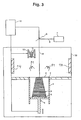
- the Fig. 3 shows a schematic view of an apparatus for producing a three-dimensional object according to a second embodiment.
- the heater has at least one resistance heater 14, which is arranged on walls of the housing 100, either circumferentially or in regions.
- the Fig. 4 shows a schematic view of an apparatus for producing a three-dimensional object according to a third embodiment.
- the heater has at least one resistance heater 16 disposed in or on the plate 12.
- the Fig. 5 shows a schematic view of an apparatus for producing a three-dimensional object according to a fourth embodiment.
- the heating device has at least one heating mat 15, which is arranged in or on the plate 12.
- the inventive method is particularly applicable in laser sintering processes, in which the temperature of the uppermost powder layer in the construction field is preheated by the further heating device to a few ° C below the necessary for solidification process temperature of the powder material, wherein the additional radiation through the laser beam 8 'another energy input to Solidifying the powder material provides. This is the case in particular when using powdered plastic material.
- the method according to the invention is applicable not only to laser sintering, but to all powder-based, generative processes in which a material or a powder material is used per layer to be applied, which is solidified by an energy-containing radiation.
- the energy-containing radiation does not necessarily have to be a laser beam 8 '. but may, for example, be an electron beam or originate from a light source other than a laser.
- the heater does not necessarily have to be formed by radiant heaters, resistance heaters and heating mats.
- the heating device can also be formed, for example, by a heating lamp or by infrared radiators. Furthermore, it is also possible to flow a tempering fluid through regions of the plate 12 or the housing 100.
- the heaters 13, 14, 15, 16 of the first to fourth embodiments may be arbitrarily combined.
Landscapes
- Engineering & Computer Science (AREA)
- Chemical & Material Sciences (AREA)
- Materials Engineering (AREA)
- Manufacturing & Machinery (AREA)
- Physics & Mathematics (AREA)
- Mechanical Engineering (AREA)
- Optics & Photonics (AREA)
- Plasma & Fusion (AREA)
- Health & Medical Sciences (AREA)
- Oral & Maxillofacial Surgery (AREA)
- Thermal Sciences (AREA)
Claims (10)
- Procédé de fabrication générative d'un objet tridimensionnel (3), avec un dispositif qui présente les éléments suivants:un cadre (1), dont la partie supérieure (2) entoure un champ de construction (6);un support (5), qui est disposé dans le cadre (1) et qui est déplaçable verticalement au moyen d'un mécanisme de levage (4) au moins en dessous du champ de construction (6);un dispositif pour produire un rayonnement énergétique (8, 8'), qui frappe de façon sélective en des points arbitraires dans le champ de construction (6), afin de fritter ou de fondre de façon sélective un matériau pulvérulent (11) se trouvant dans le champ de construction (6);un système de revêtement (10), pour déposer une couche d'un matériau pulvérulent (11) sur le support (5) ou une couche préalablement déposée du matériau pulvérulent (11);une enceinte (100), dans laquelle sont disposés au moins le cadre (1) et le support (5) et qui entoure un espace de construction;un dispositif de chauffage (13; 14; 15; 16), qui peut fournir de la chaleur en continu au moins à l'atmosphère du champ de construction ou à l'espace de construction au-dessus de celle-ci etun dispositif de chauffage (13; 14; 15; 16), qui est prévu en plus d'un autre dispositif de chauffage (81) pour le chauffage du champ de construction (6), caractérisé en ce quel'autre dispositif de chauffage (81) chauffe la couche de poudre (11) déposée au moyen du système de revêtement (10) à une température préalable nécessaire pour le frittage au moyen du rayonnement énergétique (8'); etle dispositif de chauffage (13; 14; 15; 16) fournit en plus en continu une portion de base d'une quantité de chaleur à l'atmosphère du champ de construction ou à l'espace de construction pendant la fabrication de l'objet tridimensionnel (3).
- Procédé selon la revendication précédente, dans lequel la puissance de chauffage du dispositif de chauffage (13; 14; 15; 16) reste constante pendant la fabrication de l'objet tridimensionnel.
- Procédé selon l'une quelconque des revendications précédentes, dans lequel la puissance de chauffage du dispositif de chauffage (13; 14; 15; 16) est inférieure à celle de l'autre dispositif de chauffage (81).
- Procédé selon l'une quelconque des revendications précédentes, dans lequel le dispositif de chauffage (13; 14; 15; 16) présente au moins un radiateur de chaleur (13), un chauffage par résistance (14, 15), un tapis chauffant (16) ou une lampe de chauffage.
- Procédé selon l'une quelconque des revendications précédentes, dans lequel le dispositif de chauffage (14) est disposé sur des parois de l'enceinte (100) soit en continu soit par zones.
- Procédé selon l'une quelconque des revendications précédentes, dans lequel le dispositif présente en outre une plaque (12), qui est en contact avec le cadre (1) et/ou avec l'enceinte (100) du dispositif, dans lequel le dispositif de chauffage (13; 14; 15; 16) fournit de la chaleur en continu à la plaque (12).
- Procédé selon l'une quelconque des revendications précédentes, dans lequel le dispositif de chauffage (13; 14; 15; 16) fournit plus de chaleur dans les coins du champ de construction (6) que dans d'autres parties du champ de construction (6).
- Procédé selon l'une quelconque des revendications précédentes, dans lequel le cadre (1) est un cadre interchangeable, qui peut être introduit et retiré de façon modulaire dans le dispositif.
- Procédé selon l'une quelconque des revendications précédentes, dans lequel le dispositif de chauffage (13) sert d'isolant actif du champ de construction (6), afin de compenser les pertes de chaleur du champ de construction (6) vers l'extérieur dans l'atmosphère du champ de construction et dans l'espace de construction au-dessus de celle-ci.
- Procédé selon l'une quelconque des revendications 1 à 9 avec utilisation de poudre de matière plastique comme matériau pulvérulent (11).
Applications Claiming Priority (1)
| Application Number | Priority Date | Filing Date | Title |
|---|---|---|---|
| DE102010004036A DE102010004036A1 (de) | 2010-01-05 | 2010-01-05 | Vorrichtung zum generativen Herstellen eines dreidimensionalen Objekts mit kontinuierlicher Wärmezufuhr |
Publications (2)
| Publication Number | Publication Date |
|---|---|
| EP2340925A1 EP2340925A1 (fr) | 2011-07-06 |
| EP2340925B1 true EP2340925B1 (fr) | 2013-04-03 |
Family
ID=43759421
Family Applications (1)
| Application Number | Title | Priority Date | Filing Date |
|---|---|---|---|
| EP11150079A Not-in-force EP2340925B1 (fr) | 2010-01-05 | 2011-01-04 | Procédé de fabrication générative d'un objet tridimensionnel doté d'une amenée de chaleur en continu |
Country Status (4)
| Country | Link |
|---|---|
| US (1) | US20110165340A1 (fr) |
| EP (1) | EP2340925B1 (fr) |
| JP (1) | JP5784311B2 (fr) |
| DE (1) | DE102010004036A1 (fr) |
Families Citing this family (50)
| Publication number | Priority date | Publication date | Assignee | Title |
|---|---|---|---|---|
| DE102012200161A1 (de) * | 2012-01-06 | 2013-07-11 | Evonik Industries Ag | Vorrichtung zur schichtweisen Herstellung von dreidimensionalen Objekten |
| DE102012200160A1 (de) * | 2012-01-06 | 2013-07-11 | Evonik Industries Ag | Vorrichtung zur schichtweisen Herstellung von dreidimensionalen Objekten mittels rotierendem Auftrag |
| DE102012212587A1 (de) * | 2012-07-18 | 2014-01-23 | Eos Gmbh Electro Optical Systems | Vorrichtung und Verfahren zum schichtweisen Herstellen eines dreidimensionalen Objekts |
| WO2014094882A1 (fr) * | 2012-12-21 | 2014-06-26 | European Space Agency | Procédé d'impression 3d utilisant une source de chauffage de lumière focalisée |
| JP6178491B2 (ja) | 2013-03-15 | 2017-08-09 | スリーディー システムズ インコーポレーテッド | レーザ焼結システムのための改善された粉体の分配 |
| DE102013005008A1 (de) * | 2013-03-22 | 2014-09-25 | Fraunhofer-Gesellschaft zur Förderung der angewandten Forschung e.V. | Verfahren zur Herstellung von Bauteilen aus einem Kohlenstoffnanoröhren enthaltenden Werkstoff |
| DE102013109162A1 (de) * | 2013-08-23 | 2015-02-26 | Fit Fruth Innovative Technologien Gmbh | Vorrichtung zum Herstellen dreidimensionaler Objekte |
| DE102014204580A1 (de) * | 2014-03-12 | 2015-09-17 | Siemens Aktiengesellschaft | Vorrichtung, Verfahren zum schichtweisen Generieren von Bauteilen sowie Prozesskammer |
| MX355451B (es) | 2014-06-20 | 2018-04-18 | Velo3D Inc | Aparatos, sistemas y metodos para impresion tridimensional. |
| KR101635188B1 (ko) * | 2014-07-11 | 2016-07-04 | (주)쓰리디스토리 | 태아 조형물 프린팅 서비스 시스템 및 방법 |
| KR101665939B1 (ko) * | 2014-07-18 | 2016-10-25 | 한국생산기술연구원 | 입체 조형소재 공급장치와 쾌속 입체 조형 장치 및 이를 이용한 입체 조형 방법. |
| WO2016063198A1 (fr) | 2014-10-20 | 2016-04-28 | Industrie Additive S.R.L. | Appareil et procédé de fabrication additive d'objets tridimensionnels |
| US10028841B2 (en) | 2015-01-27 | 2018-07-24 | K2M, Inc. | Interbody spacer |
| US9987051B2 (en) | 2015-01-27 | 2018-06-05 | K2M, Inc. | Interbody spacer |
| DE102015202964A1 (de) * | 2015-02-18 | 2016-08-18 | Eos Gmbh Electro Optical Systems | Vorrichtung und Verfahren zum Herstellen eines dreidimensionalen Objekts |
| US10315408B2 (en) * | 2015-04-28 | 2019-06-11 | General Electric Company | Additive manufacturing apparatus and method |
| DE102015211170A1 (de) * | 2015-06-17 | 2016-12-22 | Eos Gmbh Electro Optical Systems | Vorrichtung und Verfahren zum Herstellen eines dreidimensionalen Objekts |
| DE102015110264A1 (de) * | 2015-06-25 | 2016-12-29 | Cl Schutzrechtsverwaltungs Gmbh | Vorrichtung zur generativen Herstellung wenigstens eines dreidimensionalen Objekts |
| WO2017014964A1 (fr) * | 2015-07-20 | 2017-01-26 | Applied Materials, Inc. | Fabrication d'additif avec de multiples sources de chaleur |
| US9676145B2 (en) | 2015-11-06 | 2017-06-13 | Velo3D, Inc. | Adept three-dimensional printing |
| JP2017087562A (ja) * | 2015-11-10 | 2017-05-25 | 株式会社リコー | 三次元造形装置 |
| WO2017081812A1 (fr) * | 2015-11-13 | 2017-05-18 | 技術研究組合次世代3D積層造形技術総合開発機構 | Dispositif de fabrication additive 3d, procédé de production pour dispositif de fabrication additive 3d et programme de production pour dispositif de fabrication additive 3d |
| JP2019507236A (ja) | 2015-12-10 | 2019-03-14 | ヴェロ・スリー・ディー・インコーポレイテッド | 性能向上した3次元印刷 |
| EP3387565A2 (fr) * | 2015-12-11 | 2018-10-17 | EOS GmbH Electro Optical Systems | Procédé et dispositif destinés à tester un ensemble de données d'entrée d'un dispositif de construction par couches génératif |
| US20170239719A1 (en) | 2016-02-18 | 2017-08-24 | Velo3D, Inc. | Accurate three-dimensional printing |
| DE102016211313A1 (de) * | 2016-06-23 | 2017-12-28 | Eos Gmbh Electro Optical Systems | Automatische Justierung einer Heizungsregelung in einer generativen Schichtbauvorrichtung |
| US11691343B2 (en) | 2016-06-29 | 2023-07-04 | Velo3D, Inc. | Three-dimensional printing and three-dimensional printers |
| WO2018005439A1 (fr) | 2016-06-29 | 2018-01-04 | Velo3D, Inc. | Impression 3d et imprimantes 3d |
| WO2018128695A2 (fr) | 2016-11-07 | 2018-07-12 | Velo3D, Inc. | Écoulement des gaz lors de l'impression en trois dimensions |
| CN110214075B (zh) * | 2016-12-18 | 2022-08-23 | Csir公司 | 在增材制造设备中对材料进行预热 |
| DE102016226322A1 (de) * | 2016-12-29 | 2018-07-05 | Eos Gmbh Electro Optical Systems | Verfahren und Vorrichtung zum generativen Herstellen eines dreidimensionalen Objekts |
| WO2018129089A1 (fr) | 2017-01-05 | 2018-07-12 | Velo3D, Inc. | Optique dans l'impression en trois dimensions |
| US10369629B2 (en) | 2017-03-02 | 2019-08-06 | Veo3D, Inc. | Three-dimensional printing of three-dimensional objects |
| US11117194B2 (en) | 2017-03-15 | 2021-09-14 | Applied Materials, Inc. | Additive manufacturing having energy beam and lamp array |
| US20180281283A1 (en) | 2017-03-28 | 2018-10-04 | Velo3D, Inc. | Material manipulation in three-dimensional printing |
| WO2018194481A1 (fr) * | 2017-04-19 | 2018-10-25 | Siemens Aktiengesellschaft | Technique de fabrication additive comprenant le chauffage résistif direct d'une pièce |
| US10959855B2 (en) | 2017-05-25 | 2021-03-30 | Stryker European Holdings I, Llc | Fusion cage with integrated fixation and insertion features |
| US11006981B2 (en) | 2017-07-07 | 2021-05-18 | K2M, Inc. | Surgical implant and methods of additive manufacturing |
| KR101990305B1 (ko) * | 2017-08-18 | 2019-06-18 | (주)센트롤 | 삼차원 프린터 |
| KR101990306B1 (ko) * | 2017-08-18 | 2019-06-18 | (주)센트롤 | 삼차원 프린터 |
| EP3657903B1 (fr) * | 2017-08-24 | 2022-01-12 | Mitsubishi Heavy Industries, Ltd. | Dispositif de chauffage infrarouge |
| KR101855186B1 (ko) * | 2017-11-24 | 2018-05-11 | 원광이엔텍 주식회사 | 바인더 제트부를 구비한 3d 프린터 |
| US20210221060A1 (en) * | 2017-11-24 | 2021-07-22 | Wonkwang E&Tech Co., Ltd. | 3d printer |
| KR101855185B1 (ko) * | 2017-11-24 | 2018-05-11 | 원광이엔텍 주식회사 | 가열장치를 구비한 3d 프린터 |
| US10272525B1 (en) | 2017-12-27 | 2019-04-30 | Velo3D, Inc. | Three-dimensional printing systems and methods of their use |
| US10144176B1 (en) | 2018-01-15 | 2018-12-04 | Velo3D, Inc. | Three-dimensional printing systems and methods of their use |
| JP2019155699A (ja) * | 2018-03-12 | 2019-09-19 | 株式会社リコー | 立体造形装置及び立体造形方法 |
| JP2019155758A (ja) * | 2018-03-14 | 2019-09-19 | 株式会社リコー | 立体造形装置、熱画像測定装置、及び熱画像測定方法 |
| GB2580040B (en) * | 2018-12-19 | 2022-01-19 | Stratasys Powder Production Ltd | Heater arrangements and apparatus for layer-by-layer formation of three-dimensional objects |
| NL2026035B1 (en) | 2020-07-09 | 2022-03-15 | Additive Ind Bv | Method and apparatus for manufacturing an object by means of additive manufacturing |
Family Cites Families (15)
| Publication number | Priority date | Publication date | Assignee | Title |
|---|---|---|---|---|
| DE4400523C2 (de) * | 1994-01-11 | 1996-07-11 | Eos Electro Optical Syst | Verfahren und Vorrichtung zum Herstellen eines dreidimensionalen Objekts |
| DE19516972C1 (de) | 1995-05-09 | 1996-12-12 | Eos Electro Optical Syst | Vorrichtung zum Herstellen eines dreidimensionalen Objektes mittels Lasersintern |
| US6656410B2 (en) * | 2001-06-22 | 2003-12-02 | 3D Systems, Inc. | Recoating system for using high viscosity build materials in solid freeform fabrication |
| US6930278B1 (en) * | 2004-08-13 | 2005-08-16 | 3D Systems, Inc. | Continuous calibration of a non-contact thermal sensor for laser sintering |
| US7521652B2 (en) * | 2004-12-07 | 2009-04-21 | 3D Systems, Inc. | Controlled cooling methods and apparatus for laser sintering part-cake |
| US7569174B2 (en) * | 2004-12-07 | 2009-08-04 | 3D Systems, Inc. | Controlled densification of fusible powders in laser sintering |
| US7357629B2 (en) * | 2005-03-23 | 2008-04-15 | 3D Systems, Inc. | Apparatus and method for aligning a removable build chamber within a process chamber |
| DE102005015870B3 (de) * | 2005-04-06 | 2006-10-26 | Eos Gmbh Electro Optical Systems | Vorrichtung und Verfahren zum Herstellen eines dreidimensionalen Objekts |
| DE102005022308B4 (de) * | 2005-05-13 | 2007-03-22 | Eos Gmbh Electro Optical Systems | Vorrichtung und Verfahren zum Herstellen eines dreidimensionalen Objekts mit einem beheizten Beschichter für pulverförmiges Aufbaumaterial |
| DE102005024790A1 (de) * | 2005-05-26 | 2006-12-07 | Eos Gmbh Electro Optical Systems | Strahlungsheizung zum Heizen des Aufbaumaterials in einer Lasersintervorrichtung |
| JP4856979B2 (ja) * | 2006-02-24 | 2012-01-18 | 株式会社アスペクト | 粉末焼結積層造形装置及び粉末焼結積層造形方法 |
| DE102006053121B3 (de) * | 2006-11-10 | 2007-12-27 | Eos Gmbh Electro Optical Systems | Vorrichtung und Verfahren zum Herstellen eines dreidimensionalen Objektes mittels eines Beschichters für pulverförmiges Aufbaumaterial |
| DE102006055054A1 (de) * | 2006-11-22 | 2008-05-29 | Eos Gmbh Electro Optical Systems | Vorrichtung zum schichtweisen Herstellen eines dreidimensionalen Objekts |
| DE102006055056A1 (de) * | 2006-11-22 | 2008-05-29 | Eos Gmbh Electro Optical Systems | Beschichter zum Auftragen einer Schicht eines pulverförmigen Aufbaumaterials in einer Vorrichtung zum schichtweisen Herstellen eines dreidimensionalen Objekts |
| DE102006055055A1 (de) * | 2006-11-22 | 2008-05-29 | Eos Gmbh Electro Optical Systems | Vorrichtung zum schichtweisen Herstellen eines dreidimensionalen Objekts |
-
2010
- 2010-01-05 DE DE102010004036A patent/DE102010004036A1/de not_active Ceased
-
2011
- 2011-01-04 EP EP11150079A patent/EP2340925B1/fr not_active Not-in-force
- 2011-01-04 US US12/984,033 patent/US20110165340A1/en not_active Abandoned
- 2011-01-05 JP JP2011000325A patent/JP5784311B2/ja not_active Expired - Fee Related
Also Published As
| Publication number | Publication date |
|---|---|
| EP2340925A1 (fr) | 2011-07-06 |
| JP2011140222A (ja) | 2011-07-21 |
| DE102010004036A1 (de) | 2011-07-07 |
| JP5784311B2 (ja) | 2015-09-24 |
| US20110165340A1 (en) | 2011-07-07 |
Similar Documents
| Publication | Publication Date | Title |
|---|---|---|
| EP2340925B1 (fr) | Procédé de fabrication générative d'un objet tridimensionnel doté d'une amenée de chaleur en continu | |
| EP3099469B1 (fr) | Procédé et dispositif de commande améliorée de l'apport d'énergie dans un procédé de construction additive par génération de couches | |
| EP3036086B1 (fr) | Dispositif de fabrication d'objets tridimensionnels | |
| EP2361178B1 (fr) | Dispositif pour la fabrication générative d'un objet tridimensionnel avec une zone de construction isolée | |
| EP3059076B1 (fr) | Procede et dispositif destines a fabriquer un objet tridimensionnel | |
| DE102006053121B3 (de) | Vorrichtung und Verfahren zum Herstellen eines dreidimensionalen Objektes mittels eines Beschichters für pulverförmiges Aufbaumaterial | |
| DE102012012344B4 (de) | Verfahren und Vorrichtung zur Herstellung von Werkstücken durch Strahlschmelzen pulverförmigen Materials | |
| DE102005022308B4 (de) | Vorrichtung und Verfahren zum Herstellen eines dreidimensionalen Objekts mit einem beheizten Beschichter für pulverförmiges Aufbaumaterial | |
| EP1771267B1 (fr) | Dispositif et procede pour appliquer des couches de matiere pulverulente sur une surface | |
| EP2386405B1 (fr) | Dispositif de fabrication générative d'un objet tridimensionnel avec une délimitation du champ de construction | |
| EP3297811B1 (fr) | Procédé et dispositif de fabrication d'un objet tridimensionnel | |
| EP2785481A1 (fr) | Procédé de fabrication d'un corps façonné par montage en couches de matière en poudre | |
| DE102005030067A1 (de) | Verfahren und Vorrichtung zur Herstellung eines dreidimensionalen Gegenstandes durch ein generatives 3D-Verfahren | |
| DE102009015282B4 (de) | Verfahren und Vorrichtung zum generativen Herstellen eines dreidimensionalen Objekts | |
| EP3165349A1 (fr) | Dispositif de fabrication d'objets tridimensionnels | |
| DE102012216515A1 (de) | Verfahren zur schichtweisen Herstellung von verzugsarmen dreidimensionalen Objekten mittels Kühlelementen | |
| DE102007057450A1 (de) | Verfahren und Vorrichtung zur Herstellung eines dreidimensionalen Gegenstandes aus einem verfestigbaren Material | |
| EP3342583A1 (fr) | Procédé et dispositif de fabrication additive d'un objet tridimensionnel | |
| EP3579998A1 (fr) | Augmentation de la qualité de surface | |
| WO2017153187A1 (fr) | Procédé de construction par couches génératif présentant une résolution améliorée des détails et dispositif pour sa réalisation | |
| DE202009012628U1 (de) | Vorrichtung zum generativen Herstellen eines dreidimensionalen Objektes | |
| DE102015012844A1 (de) | Verfahren und Vorrichtung zur generativen Herstellung eines dreidimensionalen Formkörpers aus einem formlosen Material mittels Laserstrahlschmelzens, sowie Kammervorrichtung für das Verfahren und die Vorrichtung | |
| WO2018206581A1 (fr) | Entrée d'énergie spécifique à la position | |
| DE102013109160A1 (de) | Vorrichtung zum Herstellen dreidimensionaler Objekte | |
| EP4065344A1 (fr) | Procédé et dispositif pour la production de pièces façonnées en 3d à l'aide d'émetteurs de rayonnement à haute performance |
Legal Events
| Date | Code | Title | Description |
|---|---|---|---|
| PUAI | Public reference made under article 153(3) epc to a published international application that has entered the european phase |
Free format text: ORIGINAL CODE: 0009012 |
|
| AK | Designated contracting states |
Kind code of ref document: A1 Designated state(s): AL AT BE BG CH CY CZ DE DK EE ES FI FR GB GR HR HU IE IS IT LI LT LU LV MC MK MT NL NO PL PT RO RS SE SI SK SM TR |
|
| AX | Request for extension of the european patent |
Extension state: BA ME |
|
| 17P | Request for examination filed |
Effective date: 20110708 |
|
| 17Q | First examination report despatched |
Effective date: 20111011 |
|
| GRAP | Despatch of communication of intention to grant a patent |
Free format text: ORIGINAL CODE: EPIDOSNIGR1 |
|
| GRAS | Grant fee paid |
Free format text: ORIGINAL CODE: EPIDOSNIGR3 |
|
| GRAA | (expected) grant |
Free format text: ORIGINAL CODE: 0009210 |
|
| AK | Designated contracting states |
Kind code of ref document: B1 Designated state(s): AL AT BE BG CH CY CZ DE DK EE ES FI FR GB GR HR HU IE IS IT LI LT LU LV MC MK MT NL NO PL PT RO RS SE SI SK SM TR |
|
| REG | Reference to a national code |
Ref country code: GB Ref legal event code: FG4D Free format text: NOT ENGLISH |
|
| REG | Reference to a national code |
Ref country code: AT Ref legal event code: REF Ref document number: 604423 Country of ref document: AT Kind code of ref document: T Effective date: 20130415 Ref country code: CH Ref legal event code: EP |
|
| REG | Reference to a national code |
Ref country code: IE Ref legal event code: FG4D Free format text: LANGUAGE OF EP DOCUMENT: GERMAN |
|
| REG | Reference to a national code |
Ref country code: DE Ref legal event code: R096 Ref document number: 502011000578 Country of ref document: DE Effective date: 20130606 |
|
| PG25 | Lapsed in a contracting state [announced via postgrant information from national office to epo] |
Ref country code: SI Free format text: LAPSE BECAUSE OF FAILURE TO SUBMIT A TRANSLATION OF THE DESCRIPTION OR TO PAY THE FEE WITHIN THE PRESCRIBED TIME-LIMIT Effective date: 20130403 |
|
| REG | Reference to a national code |
Ref country code: NL Ref legal event code: VDEP Effective date: 20130403 |
|
| REG | Reference to a national code |
Ref country code: LT Ref legal event code: MG4D |
|
| PG25 | Lapsed in a contracting state [announced via postgrant information from national office to epo] |
Ref country code: ES Free format text: LAPSE BECAUSE OF FAILURE TO SUBMIT A TRANSLATION OF THE DESCRIPTION OR TO PAY THE FEE WITHIN THE PRESCRIBED TIME-LIMIT Effective date: 20130714 Ref country code: IS Free format text: LAPSE BECAUSE OF FAILURE TO SUBMIT A TRANSLATION OF THE DESCRIPTION OR TO PAY THE FEE WITHIN THE PRESCRIBED TIME-LIMIT Effective date: 20130803 Ref country code: PT Free format text: LAPSE BECAUSE OF FAILURE TO SUBMIT A TRANSLATION OF THE DESCRIPTION OR TO PAY THE FEE WITHIN THE PRESCRIBED TIME-LIMIT Effective date: 20130805 Ref country code: NO Free format text: LAPSE BECAUSE OF FAILURE TO SUBMIT A TRANSLATION OF THE DESCRIPTION OR TO PAY THE FEE WITHIN THE PRESCRIBED TIME-LIMIT Effective date: 20130703 Ref country code: LT Free format text: LAPSE BECAUSE OF FAILURE TO SUBMIT A TRANSLATION OF THE DESCRIPTION OR TO PAY THE FEE WITHIN THE PRESCRIBED TIME-LIMIT Effective date: 20130403 Ref country code: GR Free format text: LAPSE BECAUSE OF FAILURE TO SUBMIT A TRANSLATION OF THE DESCRIPTION OR TO PAY THE FEE WITHIN THE PRESCRIBED TIME-LIMIT Effective date: 20130704 Ref country code: SE Free format text: LAPSE BECAUSE OF FAILURE TO SUBMIT A TRANSLATION OF THE DESCRIPTION OR TO PAY THE FEE WITHIN THE PRESCRIBED TIME-LIMIT Effective date: 20130403 Ref country code: NL Free format text: LAPSE BECAUSE OF FAILURE TO SUBMIT A TRANSLATION OF THE DESCRIPTION OR TO PAY THE FEE WITHIN THE PRESCRIBED TIME-LIMIT Effective date: 20130403 Ref country code: FI Free format text: LAPSE BECAUSE OF FAILURE TO SUBMIT A TRANSLATION OF THE DESCRIPTION OR TO PAY THE FEE WITHIN THE PRESCRIBED TIME-LIMIT Effective date: 20130403 |
|
| PG25 | Lapsed in a contracting state [announced via postgrant information from national office to epo] |
Ref country code: PL Free format text: LAPSE BECAUSE OF FAILURE TO SUBMIT A TRANSLATION OF THE DESCRIPTION OR TO PAY THE FEE WITHIN THE PRESCRIBED TIME-LIMIT Effective date: 20130403 Ref country code: HR Free format text: LAPSE BECAUSE OF FAILURE TO SUBMIT A TRANSLATION OF THE DESCRIPTION OR TO PAY THE FEE WITHIN THE PRESCRIBED TIME-LIMIT Effective date: 20130403 Ref country code: RS Free format text: LAPSE BECAUSE OF FAILURE TO SUBMIT A TRANSLATION OF THE DESCRIPTION OR TO PAY THE FEE WITHIN THE PRESCRIBED TIME-LIMIT Effective date: 20130403 Ref country code: BG Free format text: LAPSE BECAUSE OF FAILURE TO SUBMIT A TRANSLATION OF THE DESCRIPTION OR TO PAY THE FEE WITHIN THE PRESCRIBED TIME-LIMIT Effective date: 20130703 Ref country code: LV Free format text: LAPSE BECAUSE OF FAILURE TO SUBMIT A TRANSLATION OF THE DESCRIPTION OR TO PAY THE FEE WITHIN THE PRESCRIBED TIME-LIMIT Effective date: 20130403 Ref country code: CY Free format text: LAPSE BECAUSE OF FAILURE TO SUBMIT A TRANSLATION OF THE DESCRIPTION OR TO PAY THE FEE WITHIN THE PRESCRIBED TIME-LIMIT Effective date: 20130403 |
|
| PG25 | Lapsed in a contracting state [announced via postgrant information from national office to epo] |
Ref country code: EE Free format text: LAPSE BECAUSE OF FAILURE TO SUBMIT A TRANSLATION OF THE DESCRIPTION OR TO PAY THE FEE WITHIN THE PRESCRIBED TIME-LIMIT Effective date: 20130403 Ref country code: DK Free format text: LAPSE BECAUSE OF FAILURE TO SUBMIT A TRANSLATION OF THE DESCRIPTION OR TO PAY THE FEE WITHIN THE PRESCRIBED TIME-LIMIT Effective date: 20130403 Ref country code: SK Free format text: LAPSE BECAUSE OF FAILURE TO SUBMIT A TRANSLATION OF THE DESCRIPTION OR TO PAY THE FEE WITHIN THE PRESCRIBED TIME-LIMIT Effective date: 20130403 Ref country code: CZ Free format text: LAPSE BECAUSE OF FAILURE TO SUBMIT A TRANSLATION OF THE DESCRIPTION OR TO PAY THE FEE WITHIN THE PRESCRIBED TIME-LIMIT Effective date: 20130403 |
|
| PLBE | No opposition filed within time limit |
Free format text: ORIGINAL CODE: 0009261 |
|
| STAA | Information on the status of an ep patent application or granted ep patent |
Free format text: STATUS: NO OPPOSITION FILED WITHIN TIME LIMIT |
|
| PG25 | Lapsed in a contracting state [announced via postgrant information from national office to epo] |
Ref country code: RO Free format text: LAPSE BECAUSE OF FAILURE TO SUBMIT A TRANSLATION OF THE DESCRIPTION OR TO PAY THE FEE WITHIN THE PRESCRIBED TIME-LIMIT Effective date: 20130403 |
|
| 26N | No opposition filed |
Effective date: 20140106 |
|
| REG | Reference to a national code |
Ref country code: DE Ref legal event code: R097 Ref document number: 502011000578 Country of ref document: DE Effective date: 20140106 |
|
| BERE | Be: lapsed |
Owner name: EOS G.M.B.H. ELECTRO OPTICAL SYSTEMS Effective date: 20140131 |
|
| PG25 | Lapsed in a contracting state [announced via postgrant information from national office to epo] |
Ref country code: MC Free format text: LAPSE BECAUSE OF FAILURE TO SUBMIT A TRANSLATION OF THE DESCRIPTION OR TO PAY THE FEE WITHIN THE PRESCRIBED TIME-LIMIT Effective date: 20130403 Ref country code: LU Free format text: LAPSE BECAUSE OF FAILURE TO SUBMIT A TRANSLATION OF THE DESCRIPTION OR TO PAY THE FEE WITHIN THE PRESCRIBED TIME-LIMIT Effective date: 20140104 |
|
| REG | Reference to a national code |
Ref country code: CH Ref legal event code: PL |
|
| PG25 | Lapsed in a contracting state [announced via postgrant information from national office to epo] |
Ref country code: LI Free format text: LAPSE BECAUSE OF NON-PAYMENT OF DUE FEES Effective date: 20140131 Ref country code: CH Free format text: LAPSE BECAUSE OF NON-PAYMENT OF DUE FEES Effective date: 20140131 |
|
| REG | Reference to a national code |
Ref country code: IE Ref legal event code: MM4A |
|
| PG25 | Lapsed in a contracting state [announced via postgrant information from national office to epo] |
Ref country code: IE Free format text: LAPSE BECAUSE OF NON-PAYMENT OF DUE FEES Effective date: 20140104 Ref country code: BE Free format text: LAPSE BECAUSE OF NON-PAYMENT OF DUE FEES Effective date: 20140131 |
|
| REG | Reference to a national code |
Ref country code: FR Ref legal event code: PLFP Year of fee payment: 6 |
|
| PG25 | Lapsed in a contracting state [announced via postgrant information from national office to epo] |
Ref country code: MT Free format text: LAPSE BECAUSE OF FAILURE TO SUBMIT A TRANSLATION OF THE DESCRIPTION OR TO PAY THE FEE WITHIN THE PRESCRIBED TIME-LIMIT Effective date: 20130403 |
|
| PG25 | Lapsed in a contracting state [announced via postgrant information from national office to epo] |
Ref country code: SM Free format text: LAPSE BECAUSE OF FAILURE TO SUBMIT A TRANSLATION OF THE DESCRIPTION OR TO PAY THE FEE WITHIN THE PRESCRIBED TIME-LIMIT Effective date: 20130403 |
|
| PG25 | Lapsed in a contracting state [announced via postgrant information from national office to epo] |
Ref country code: TR Free format text: LAPSE BECAUSE OF FAILURE TO SUBMIT A TRANSLATION OF THE DESCRIPTION OR TO PAY THE FEE WITHIN THE PRESCRIBED TIME-LIMIT Effective date: 20130403 Ref country code: HU Free format text: LAPSE BECAUSE OF FAILURE TO SUBMIT A TRANSLATION OF THE DESCRIPTION OR TO PAY THE FEE WITHIN THE PRESCRIBED TIME-LIMIT; INVALID AB INITIO Effective date: 20110104 |
|
| REG | Reference to a national code |
Ref country code: DE Ref legal event code: R079 Ref document number: 502011000578 Country of ref document: DE Free format text: PREVIOUS MAIN CLASS: B29C0067000000 Ipc: B29C0064106000 |
|
| REG | Reference to a national code |
Ref country code: FR Ref legal event code: PLFP Year of fee payment: 7 |
|
| REG | Reference to a national code |
Ref country code: AT Ref legal event code: MM01 Ref document number: 604423 Country of ref document: AT Kind code of ref document: T Effective date: 20160104 |
|
| PGFP | Annual fee paid to national office [announced via postgrant information from national office to epo] |
Ref country code: DE Payment date: 20170120 Year of fee payment: 7 Ref country code: FR Payment date: 20170120 Year of fee payment: 7 |
|
| PG25 | Lapsed in a contracting state [announced via postgrant information from national office to epo] |
Ref country code: AT Free format text: LAPSE BECAUSE OF NON-PAYMENT OF DUE FEES Effective date: 20160104 |
|
| PGFP | Annual fee paid to national office [announced via postgrant information from national office to epo] |
Ref country code: GB Payment date: 20170119 Year of fee payment: 7 |
|
| PGFP | Annual fee paid to national office [announced via postgrant information from national office to epo] |
Ref country code: IT Payment date: 20170124 Year of fee payment: 7 |
|
| PG25 | Lapsed in a contracting state [announced via postgrant information from national office to epo] |
Ref country code: MK Free format text: LAPSE BECAUSE OF FAILURE TO SUBMIT A TRANSLATION OF THE DESCRIPTION OR TO PAY THE FEE WITHIN THE PRESCRIBED TIME-LIMIT Effective date: 20130403 |
|
| REG | Reference to a national code |
Ref country code: DE Ref legal event code: R119 Ref document number: 502011000578 Country of ref document: DE |
|
| GBPC | Gb: european patent ceased through non-payment of renewal fee |
Effective date: 20180104 |
|
| PG25 | Lapsed in a contracting state [announced via postgrant information from national office to epo] |
Ref country code: AL Free format text: LAPSE BECAUSE OF FAILURE TO SUBMIT A TRANSLATION OF THE DESCRIPTION OR TO PAY THE FEE WITHIN THE PRESCRIBED TIME-LIMIT Effective date: 20130403 Ref country code: FR Free format text: LAPSE BECAUSE OF NON-PAYMENT OF DUE FEES Effective date: 20180131 Ref country code: DE Free format text: LAPSE BECAUSE OF NON-PAYMENT OF DUE FEES Effective date: 20180801 |
|
| REG | Reference to a national code |
Ref country code: FR Ref legal event code: ST Effective date: 20180928 |
|
| PG25 | Lapsed in a contracting state [announced via postgrant information from national office to epo] |
Ref country code: GB Free format text: LAPSE BECAUSE OF NON-PAYMENT OF DUE FEES Effective date: 20180104 |
|
| PG25 | Lapsed in a contracting state [announced via postgrant information from national office to epo] |
Ref country code: IT Free format text: LAPSE BECAUSE OF NON-PAYMENT OF DUE FEES Effective date: 20180104 |