EP3059076B1 - Procede et dispositif destines a fabriquer un objet tridimensionnel - Google Patents
Procede et dispositif destines a fabriquer un objet tridimensionnel Download PDFInfo
- Publication number
- EP3059076B1 EP3059076B1 EP16155718.6A EP16155718A EP3059076B1 EP 3059076 B1 EP3059076 B1 EP 3059076B1 EP 16155718 A EP16155718 A EP 16155718A EP 3059076 B1 EP3059076 B1 EP 3059076B1
- Authority
- EP
- European Patent Office
- Prior art keywords
- temperature
- control unit
- construction field
- construction
- partial surface
- Prior art date
- Legal status (The legal status is an assumption and is not a legal conclusion. Google has not performed a legal analysis and makes no representation as to the accuracy of the status listed.)
- Active
Links
- 238000000034 method Methods 0.000 title claims description 35
- 238000010438 heat treatment Methods 0.000 claims description 92
- 238000010276 construction Methods 0.000 claims description 69
- 239000000843 powder Substances 0.000 claims description 54
- 230000005855 radiation Effects 0.000 claims description 41
- 239000002245 particle Substances 0.000 claims description 29
- 238000001816 cooling Methods 0.000 claims description 22
- 230000005670 electromagnetic radiation Effects 0.000 claims description 22
- 239000004035 construction material Substances 0.000 claims description 20
- 239000000463 material Substances 0.000 claims description 18
- 230000004913 activation Effects 0.000 claims description 11
- 230000009471 action Effects 0.000 claims description 5
- 238000002474 experimental method Methods 0.000 claims description 2
- 238000007596 consolidation process Methods 0.000 claims 2
- 238000013500 data storage Methods 0.000 claims 2
- 230000005540 biological transmission Effects 0.000 claims 1
- 239000004566 building material Substances 0.000 description 61
- 238000004519 manufacturing process Methods 0.000 description 21
- 238000007711 solidification Methods 0.000 description 17
- 230000008023 solidification Effects 0.000 description 17
- 230000008569 process Effects 0.000 description 15
- 238000012546 transfer Methods 0.000 description 11
- 230000006870 function Effects 0.000 description 7
- 238000012360 testing method Methods 0.000 description 6
- 238000002844 melting Methods 0.000 description 5
- 230000008018 melting Effects 0.000 description 5
- 230000035882 stress Effects 0.000 description 5
- 230000017525 heat dissipation Effects 0.000 description 3
- 239000000523 sample Substances 0.000 description 3
- 239000007787 solid Substances 0.000 description 3
- 239000000126 substance Substances 0.000 description 3
- 238000001931 thermography Methods 0.000 description 3
- 238000000149 argon plasma sintering Methods 0.000 description 2
- 230000006399 behavior Effects 0.000 description 2
- 230000001680 brushing effect Effects 0.000 description 2
- 230000008859 change Effects 0.000 description 2
- 238000004590 computer program Methods 0.000 description 2
- 230000001419 dependent effect Effects 0.000 description 2
- 238000009826 distribution Methods 0.000 description 2
- 238000010894 electron beam technology Methods 0.000 description 2
- 238000009413 insulation Methods 0.000 description 2
- 238000005259 measurement Methods 0.000 description 2
- 239000012254 powdered material Substances 0.000 description 2
- 230000009467 reduction Effects 0.000 description 2
- 229910000831 Steel Inorganic materials 0.000 description 1
- 238000004458 analytical method Methods 0.000 description 1
- 229910001423 beryllium ion Inorganic materials 0.000 description 1
- 238000009529 body temperature measurement Methods 0.000 description 1
- 238000004364 calculation method Methods 0.000 description 1
- 239000000919 ceramic Substances 0.000 description 1
- 230000002939 deleterious effect Effects 0.000 description 1
- 238000001514 detection method Methods 0.000 description 1
- 238000011161 development Methods 0.000 description 1
- 230000018109 developmental process Effects 0.000 description 1
- 230000001939 inductive effect Effects 0.000 description 1
- 238000009434 installation Methods 0.000 description 1
- 239000012212 insulator Substances 0.000 description 1
- 239000012768 molten material Substances 0.000 description 1
- 238000012544 monitoring process Methods 0.000 description 1
- 230000000704 physical effect Effects 0.000 description 1
- 229920006260 polyaryletherketone Polymers 0.000 description 1
- 230000000630 rising effect Effects 0.000 description 1
- 238000000110 selective laser sintering Methods 0.000 description 1
- 238000005245 sintering Methods 0.000 description 1
- 239000010959 steel Substances 0.000 description 1
- 238000003860 storage Methods 0.000 description 1
- 238000010408 sweeping Methods 0.000 description 1
- 230000008646 thermal stress Effects 0.000 description 1
Images


Classifications
-
- B—PERFORMING OPERATIONS; TRANSPORTING
- B22—CASTING; POWDER METALLURGY
- B22F—WORKING METALLIC POWDER; MANUFACTURE OF ARTICLES FROM METALLIC POWDER; MAKING METALLIC POWDER; APPARATUS OR DEVICES SPECIALLY ADAPTED FOR METALLIC POWDER
- B22F10/00—Additive manufacturing of workpieces or articles from metallic powder
-
- B—PERFORMING OPERATIONS; TRANSPORTING
- B29—WORKING OF PLASTICS; WORKING OF SUBSTANCES IN A PLASTIC STATE IN GENERAL
- B29C—SHAPING OR JOINING OF PLASTICS; SHAPING OF MATERIAL IN A PLASTIC STATE, NOT OTHERWISE PROVIDED FOR; AFTER-TREATMENT OF THE SHAPED PRODUCTS, e.g. REPAIRING
- B29C64/00—Additive manufacturing, i.e. manufacturing of three-dimensional [3D] objects by additive deposition, additive agglomeration or additive layering, e.g. by 3D printing, stereolithography or selective laser sintering
- B29C64/20—Apparatus for additive manufacturing; Details thereof or accessories therefor
- B29C64/295—Heating elements
-
- B—PERFORMING OPERATIONS; TRANSPORTING
- B22—CASTING; POWDER METALLURGY
- B22F—WORKING METALLIC POWDER; MANUFACTURE OF ARTICLES FROM METALLIC POWDER; MAKING METALLIC POWDER; APPARATUS OR DEVICES SPECIALLY ADAPTED FOR METALLIC POWDER
- B22F10/00—Additive manufacturing of workpieces or articles from metallic powder
- B22F10/20—Direct sintering or melting
- B22F10/28—Powder bed fusion, e.g. selective laser melting [SLM] or electron beam melting [EBM]
-
- B—PERFORMING OPERATIONS; TRANSPORTING
- B22—CASTING; POWDER METALLURGY
- B22F—WORKING METALLIC POWDER; MANUFACTURE OF ARTICLES FROM METALLIC POWDER; MAKING METALLIC POWDER; APPARATUS OR DEVICES SPECIALLY ADAPTED FOR METALLIC POWDER
- B22F10/00—Additive manufacturing of workpieces or articles from metallic powder
- B22F10/30—Process control
- B22F10/36—Process control of energy beam parameters
- B22F10/362—Process control of energy beam parameters for preheating
-
- B—PERFORMING OPERATIONS; TRANSPORTING
- B22—CASTING; POWDER METALLURGY
- B22F—WORKING METALLIC POWDER; MANUFACTURE OF ARTICLES FROM METALLIC POWDER; MAKING METALLIC POWDER; APPARATUS OR DEVICES SPECIALLY ADAPTED FOR METALLIC POWDER
- B22F12/00—Apparatus or devices specially adapted for additive manufacturing; Auxiliary means for additive manufacturing; Combinations of additive manufacturing apparatus or devices with other processing apparatus or devices
- B22F12/10—Auxiliary heating means
- B22F12/13—Auxiliary heating means to preheat the material
-
- B—PERFORMING OPERATIONS; TRANSPORTING
- B22—CASTING; POWDER METALLURGY
- B22F—WORKING METALLIC POWDER; MANUFACTURE OF ARTICLES FROM METALLIC POWDER; MAKING METALLIC POWDER; APPARATUS OR DEVICES SPECIALLY ADAPTED FOR METALLIC POWDER
- B22F12/00—Apparatus or devices specially adapted for additive manufacturing; Auxiliary means for additive manufacturing; Combinations of additive manufacturing apparatus or devices with other processing apparatus or devices
- B22F12/90—Means for process control, e.g. cameras or sensors
-
- B—PERFORMING OPERATIONS; TRANSPORTING
- B23—MACHINE TOOLS; METAL-WORKING NOT OTHERWISE PROVIDED FOR
- B23K—SOLDERING OR UNSOLDERING; WELDING; CLADDING OR PLATING BY SOLDERING OR WELDING; CUTTING BY APPLYING HEAT LOCALLY, e.g. FLAME CUTTING; WORKING BY LASER BEAM
- B23K26/00—Working by laser beam, e.g. welding, cutting or boring
- B23K26/0006—Working by laser beam, e.g. welding, cutting or boring taking account of the properties of the material involved
-
- B—PERFORMING OPERATIONS; TRANSPORTING
- B23—MACHINE TOOLS; METAL-WORKING NOT OTHERWISE PROVIDED FOR
- B23K—SOLDERING OR UNSOLDERING; WELDING; CLADDING OR PLATING BY SOLDERING OR WELDING; CUTTING BY APPLYING HEAT LOCALLY, e.g. FLAME CUTTING; WORKING BY LASER BEAM
- B23K26/00—Working by laser beam, e.g. welding, cutting or boring
- B23K26/14—Working by laser beam, e.g. welding, cutting or boring using a fluid stream, e.g. a jet of gas, in conjunction with the laser beam; Nozzles therefor
- B23K26/144—Working by laser beam, e.g. welding, cutting or boring using a fluid stream, e.g. a jet of gas, in conjunction with the laser beam; Nozzles therefor the fluid stream containing particles, e.g. powder
-
- B—PERFORMING OPERATIONS; TRANSPORTING
- B23—MACHINE TOOLS; METAL-WORKING NOT OTHERWISE PROVIDED FOR
- B23K—SOLDERING OR UNSOLDERING; WELDING; CLADDING OR PLATING BY SOLDERING OR WELDING; CUTTING BY APPLYING HEAT LOCALLY, e.g. FLAME CUTTING; WORKING BY LASER BEAM
- B23K26/00—Working by laser beam, e.g. welding, cutting or boring
- B23K26/34—Laser welding for purposes other than joining
- B23K26/342—Build-up welding
-
- B—PERFORMING OPERATIONS; TRANSPORTING
- B29—WORKING OF PLASTICS; WORKING OF SUBSTANCES IN A PLASTIC STATE IN GENERAL
- B29C—SHAPING OR JOINING OF PLASTICS; SHAPING OF MATERIAL IN A PLASTIC STATE, NOT OTHERWISE PROVIDED FOR; AFTER-TREATMENT OF THE SHAPED PRODUCTS, e.g. REPAIRING
- B29C64/00—Additive manufacturing, i.e. manufacturing of three-dimensional [3D] objects by additive deposition, additive agglomeration or additive layering, e.g. by 3D printing, stereolithography or selective laser sintering
- B29C64/20—Apparatus for additive manufacturing; Details thereof or accessories therefor
- B29C64/264—Arrangements for irradiation
- B29C64/268—Arrangements for irradiation using laser beams; using electron beams [EB]
-
- B—PERFORMING OPERATIONS; TRANSPORTING
- B33—ADDITIVE MANUFACTURING TECHNOLOGY
- B33Y—ADDITIVE MANUFACTURING, i.e. MANUFACTURING OF THREE-DIMENSIONAL [3-D] OBJECTS BY ADDITIVE DEPOSITION, ADDITIVE AGGLOMERATION OR ADDITIVE LAYERING, e.g. BY 3-D PRINTING, STEREOLITHOGRAPHY OR SELECTIVE LASER SINTERING
- B33Y30/00—Apparatus for additive manufacturing; Details thereof or accessories therefor
-
- B—PERFORMING OPERATIONS; TRANSPORTING
- B22—CASTING; POWDER METALLURGY
- B22F—WORKING METALLIC POWDER; MANUFACTURE OF ARTICLES FROM METALLIC POWDER; MAKING METALLIC POWDER; APPARATUS OR DEVICES SPECIALLY ADAPTED FOR METALLIC POWDER
- B22F12/00—Apparatus or devices specially adapted for additive manufacturing; Auxiliary means for additive manufacturing; Combinations of additive manufacturing apparatus or devices with other processing apparatus or devices
- B22F12/20—Cooling means
-
- B—PERFORMING OPERATIONS; TRANSPORTING
- B22—CASTING; POWDER METALLURGY
- B22F—WORKING METALLIC POWDER; MANUFACTURE OF ARTICLES FROM METALLIC POWDER; MAKING METALLIC POWDER; APPARATUS OR DEVICES SPECIALLY ADAPTED FOR METALLIC POWDER
- B22F2999/00—Aspects linked to processes or compositions used in powder metallurgy
-
- B—PERFORMING OPERATIONS; TRANSPORTING
- B29—WORKING OF PLASTICS; WORKING OF SUBSTANCES IN A PLASTIC STATE IN GENERAL
- B29C—SHAPING OR JOINING OF PLASTICS; SHAPING OF MATERIAL IN A PLASTIC STATE, NOT OTHERWISE PROVIDED FOR; AFTER-TREATMENT OF THE SHAPED PRODUCTS, e.g. REPAIRING
- B29C64/00—Additive manufacturing, i.e. manufacturing of three-dimensional [3D] objects by additive deposition, additive agglomeration or additive layering, e.g. by 3D printing, stereolithography or selective laser sintering
- B29C64/10—Processes of additive manufacturing
- B29C64/141—Processes of additive manufacturing using only solid materials
- B29C64/153—Processes of additive manufacturing using only solid materials using layers of powder being selectively joined, e.g. by selective laser sintering or melting
-
- B—PERFORMING OPERATIONS; TRANSPORTING
- B29—WORKING OF PLASTICS; WORKING OF SUBSTANCES IN A PLASTIC STATE IN GENERAL
- B29C—SHAPING OR JOINING OF PLASTICS; SHAPING OF MATERIAL IN A PLASTIC STATE, NOT OTHERWISE PROVIDED FOR; AFTER-TREATMENT OF THE SHAPED PRODUCTS, e.g. REPAIRING
- B29C64/00—Additive manufacturing, i.e. manufacturing of three-dimensional [3D] objects by additive deposition, additive agglomeration or additive layering, e.g. by 3D printing, stereolithography or selective laser sintering
- B29C64/10—Processes of additive manufacturing
- B29C64/188—Processes of additive manufacturing involving additional operations performed on the added layers, e.g. smoothing, grinding or thickness control
-
- B—PERFORMING OPERATIONS; TRANSPORTING
- B29—WORKING OF PLASTICS; WORKING OF SUBSTANCES IN A PLASTIC STATE IN GENERAL
- B29C—SHAPING OR JOINING OF PLASTICS; SHAPING OF MATERIAL IN A PLASTIC STATE, NOT OTHERWISE PROVIDED FOR; AFTER-TREATMENT OF THE SHAPED PRODUCTS, e.g. REPAIRING
- B29C64/00—Additive manufacturing, i.e. manufacturing of three-dimensional [3D] objects by additive deposition, additive agglomeration or additive layering, e.g. by 3D printing, stereolithography or selective laser sintering
- B29C64/30—Auxiliary operations or equipment
- B29C64/386—Data acquisition or data processing for additive manufacturing
- B29C64/393—Data acquisition or data processing for additive manufacturing for controlling or regulating additive manufacturing processes
-
- B—PERFORMING OPERATIONS; TRANSPORTING
- B33—ADDITIVE MANUFACTURING TECHNOLOGY
- B33Y—ADDITIVE MANUFACTURING, i.e. MANUFACTURING OF THREE-DIMENSIONAL [3-D] OBJECTS BY ADDITIVE DEPOSITION, ADDITIVE AGGLOMERATION OR ADDITIVE LAYERING, e.g. BY 3-D PRINTING, STEREOLITHOGRAPHY OR SELECTIVE LASER SINTERING
- B33Y10/00—Processes of additive manufacturing
-
- C—CHEMISTRY; METALLURGY
- C04—CEMENTS; CONCRETE; ARTIFICIAL STONE; CERAMICS; REFRACTORIES
- C04B—LIME, MAGNESIA; SLAG; CEMENTS; COMPOSITIONS THEREOF, e.g. MORTARS, CONCRETE OR LIKE BUILDING MATERIALS; ARTIFICIAL STONE; CERAMICS; REFRACTORIES; TREATMENT OF NATURAL STONE
- C04B2235/00—Aspects relating to ceramic starting mixtures or sintered ceramic products
- C04B2235/65—Aspects relating to heat treatments of ceramic bodies such as green ceramics or pre-sintered ceramics, e.g. burning, sintering or melting processes
- C04B2235/66—Specific sintering techniques, e.g. centrifugal sintering
- C04B2235/665—Local sintering, e.g. laser sintering
-
- C—CHEMISTRY; METALLURGY
- C04—CEMENTS; CONCRETE; ARTIFICIAL STONE; CERAMICS; REFRACTORIES
- C04B—LIME, MAGNESIA; SLAG; CEMENTS; COMPOSITIONS THEREOF, e.g. MORTARS, CONCRETE OR LIKE BUILDING MATERIALS; ARTIFICIAL STONE; CERAMICS; REFRACTORIES; TREATMENT OF NATURAL STONE
- C04B35/00—Shaped ceramic products characterised by their composition; Ceramics compositions; Processing powders of inorganic compounds preparatory to the manufacturing of ceramic products
- C04B35/622—Forming processes; Processing powders of inorganic compounds preparatory to the manufacturing of ceramic products
- C04B35/64—Burning or sintering processes
-
- Y—GENERAL TAGGING OF NEW TECHNOLOGICAL DEVELOPMENTS; GENERAL TAGGING OF CROSS-SECTIONAL TECHNOLOGIES SPANNING OVER SEVERAL SECTIONS OF THE IPC; TECHNICAL SUBJECTS COVERED BY FORMER USPC CROSS-REFERENCE ART COLLECTIONS [XRACs] AND DIGESTS
- Y02—TECHNOLOGIES OR APPLICATIONS FOR MITIGATION OR ADAPTATION AGAINST CLIMATE CHANGE
- Y02P—CLIMATE CHANGE MITIGATION TECHNOLOGIES IN THE PRODUCTION OR PROCESSING OF GOODS
- Y02P10/00—Technologies related to metal processing
- Y02P10/25—Process efficiency
Definitions
- the present invention relates to an apparatus and a method for producing a three-dimensional object by selective layer-by-layer solidification of powdery building material by energy input.
- a method of this kind is used, for example, for rapid prototyping, rapid tooling or rapid manufacturing.
- An example of such a process is known as "selective laser sintering or laser melting.”
- powder is selectively solidified by selective irradiation with a laser beam, by means of the introduced with the laser beam thermal energy, the material is completely or superficially melted, so that the powder grains have joined together after the subsequent cooling.
- an electron beam can be used for the energy input.
- WO 2014/012764 A1 describes a method and an apparatus for producing a three-dimensional object by layering and selectively solidifying a powdery building material.
- a plurality of thin powder sublayers are applied, which are solidified only after the application of the last powder sublayer.
- solidification of the material takes place after the application of each layer.
- EP 1 388 411 A1 describes a method of manufacturing a three-dimensional object, wherein a step of controllably heating a deposited powder layer and determining the amount of heat taken up by the powder per temperature interval is performed for at least two temperature intervals before or during the actual building process.
- EP 2 340 925 A1 describes a device for generatively producing a three-dimensional object with continuous heat supply.
- a heating device continuously supplies heat to at least the construction field environment or the installation space above it.
- WO 2006/105827 A1 describes an apparatus and a method for producing three-dimensional objects, in which a temperature measuring device for non-contact measurement of the temperature of the building material is present.
- the position of the measuring range of the temperature measuring device is changed independently of the position of the area on which the electromagnetic or particle radiation acts to solidify the building material.
- EP 1 583 626 B1 describes an apparatus and a method by which objects are manufactured despite higher aimed at production speed with high accuracy.
- it is proposed to supply the energy beam alternately to different regions of the object cross section when solidifying a layer of a powdered building material to generate a cross section of the object to be produced.
- the powder layer to be solidified is recorded during the manufacturing process by means of a thermal imaging camera and after an analysis of the temperature distribution in the powder layer specifically corrects the temperature at individual points of the powder layer.
- the calculations required to determine the manner of propagation of the heat energy after the energy input by means of the energy beam make the process relatively complicated.
- Tensions caused by the action in EP 1 583 626 B1 are to be reduced occur in objects produced by a generative layer construction method, especially when the temperature of the powder layer, before the energy beam impinges on them, is significantly below the temperature at which a solidification of the powdered material takes place by melting the same. In particular, but not only, such stress problems occur in metallic powder materials.
- An inventive device for producing a three-dimensional object by means of layered solidification of a powdered building material by electromagnetic radiation or particle radiation contains: a height-movable support on which the object is constructed and the horizontal extent defines a construction field, an irradiation device for directing the electromagnetic radiation or particle radiation on an object cross-section corresponding areas of a deposited layer of the building material within the construction field and a control unit for controlling the irradiation device such that the powder particles of the building material connect to one another at the locations where the electromagnetic radiation or particle radiation impinges on the building material.
- a selective heating device is provided, which is designed so that any part surface of the construction field can be heated to a plateau temperature.
- the plateau temperature is significantly higher than an at least regional temperature of the construction field outside the subarea.
- the control unit is further designed so that it controls the selective heating device so that the partial surface has a predefined minimum distance d to the edge of the construction field.
- the entire construction field does not have to be brought to a high temperature in order to reduce the temperature difference between the molten material and its surroundings, in particular the surrounding unconsolidated powder material, and as a consequence to reduce stress cracks. Rather, the device is protected from the high temperatures by a minimum distance from the edge of the construction field by the unconsolidated powdery building material, which surrounds an object to be produced, serves as an insulator. Furthermore, a powder layer in the construction field can be selectively heated, ie only at selected locations.
- the plateau temperature may e.g. a temperature of the unconsolidated building material immediately before supplying the energy for solidifying the same.
- the plateau temperature can also be a temperature which is adjusted so that an already solidified object cross-section cools only slowly.
- the plateau temperature is at most 200 ° C, more preferably at most 150 ° C, and most preferably at most 100 ° C lower than an activation temperature of the building material, i. a temperature at which, by modifying the chemical and / or physical properties of the powder, the powder particles are bonded together in such a way that after cooling a solid body is formed.
- the energy introduced by the irradiation device is largely used for the actual solidification process and not so much for the preheating of the powder. As a result, the solidification process can take place more controlled overall.
- the control unit preferably has a data memory in which material parameter values relating to a thermal behavior of at least one building material, preferably different construction materials, are stored. This makes it possible in particular to control the heating process as a function of the building material used in the device.
- the control unit further determines the minimum distance d to the edge of the construction field as a function of the material parameter values of the building material used stored in the data memory. This makes it possible to set the minimum distance to the edge of the construction field as a function of the respective insulating properties of an amount of the unconsolidated building material surrounding the object to be manufactured.
- this minimum distance should be sufficiently dimensioned to protect other areas of the device from damage due to high temperature stress.
- control unit preferably defines the shape of a part surface to be selectively heated, including its shape and / or dimensions, depending on the shape of the object cross-section to be solidified.
- the area of the powder layer to be heated by means of the selective heating device can be particularly effectively limited to the absolutely necessary level, whereby the energy efficiency is improved.
- control unit preferably defines a partial surface such that its surface dimension is greater than that of the object cross-section to be solidified.
- the selective heating device in operation directs electromagnetic radiation, in particular laser radiation, and / or particle radiation onto the surface of the building material.
- electromagnetic radiation in particular laser radiation
- the heating can be done with high local selectivity.
- laser radiation is used to selectively heat and this laser radiation has the same wavelength as that of the irradiation device, if this also uses a laser, one can branch the laser radiation for selective heating from the same laser source, which is also used for the generation of the solidification radiation.
- the construction field is surrounded by a container, wherein additionally a cooling and / or heating device for cooling and / or heating of the container is present.
- a cooling and / or heating device for cooling and / or heating of the container is present.
- heat can additionally be supplied to the pulverulent building material, so that the selective heating device can be dimensioned smaller.
- heat can be dissipated specifically and surrounding the container parts of the device can be protected from the heat in the construction field.
- stationary thermal conditions in the environment of the container can be produced by cooling down a container wall to a predetermined temperature value.
- suitable cooling it is also possible to reduce the above-executed minimum distance from the edge of the construction field. Such a reduction is preferably made as a function of determined (i.e., measured or computationally determined) cooling parameter values of the cooling.
- the device for producing a three-dimensional object may also have a temperature measuring device, which performs a temperature measurement at least in a partial region of the construction field, preferably near its edge.
- a temperature measuring device which performs a temperature measurement at least in a partial region of the construction field, preferably near its edge.
- the control unit during the manufacturing process of objects controlling the heat input by the selective heating device so that a minimum plateau temperature to which a partial area of the construction field is heated, in at least one operating state (ie not necessarily during the entire manufacturing process in a layer, but if necessary, also temporarily) by a predetermined amount above one of the temperature measuring device to the control unit transmitted temperature is.
- the heating of the building material can be adjusted by means of the selective heating device specifically to the present at a given time in the device specific conditions.
- the control unit can also control the selective heating device such that the partial surface is heated to a minimum plateau temperature which is at least 300 ° C., preferably at least 400 ° C., more preferably at least 800 ° C. above that transmitted by the temperature measuring device to the control unit Temperature is.
- the plateau temperature can be set as close as possible to the activation temperature.
- control unit controls the selective heating device such that the latter heats at least to the plateau temperature before and / or after directing the electromagnetic radiation or particle radiation of the irradiation device onto the building material, the selective heating device heats a partial surface of the construction field.
- the heating process of the building material and / or the cooling process after solidifying the same can be done in a more controlled manner. Without the selective heating, temperature changes on the powdery building material during the sweeping of the construction field with the irradiation device are more abrupt and larger.
- control unit can control the selective heating device in such a way that it heats a partial surface of the construction field after directing the electromagnetic radiation or particle radiation of the irradiation device such that a cooling rate in the partial surface of at least 30%, preferably at least 50%, is particularly preferred at least 70% less than without the action of the selective heating device.
- a method for producing a three-dimensional object by layered solidification of a powdery building material by electromagnetic radiation or particle radiation is possible, in which an object on a height-adjustable support whose horizontal extension defines a construction field is constructed and electromagnetic radiation or particle radiation by means an irradiation device is directed onto an object cross section corresponding areas of an applied layer of the building material within the construction field, wherein the irradiation device is controlled with a control unit such that the powder particles of the building material at the locations where the electromagnetic radiation or particle radiation impinges on the building material connect with each other.
- any part surface of the construction field is heated to a plateau temperature, wherein the plateau temperature is significantly higher than an at least partially present temperature of the construction field outside the part surface.
- the control unit controls the selective heating device so that the partial surface has a predefined minimum distance d to the edge of the construction field.
- the minimum distance d can be determined as a function of preliminary tests in which the heat transfer capacity of the building material used in the method is determined. In this way, the heating of the building material can be specifically adapted to the building material used with its characteristic thermal properties.
- a device 100 which is suitable for carrying out a method according to the invention.
- an object 3 is constructed in an upwardly open container 1 with a wall 1a.
- a movable in a vertical direction V carrier is arranged, the support plate 2 shown schematically the container 1 down closes and thus forms its bottom.
- the object 3 to be formed in the container 1 is shown in an intermediate state with a plurality of already solidified cross sections 30, the object 3 being surrounded by powdery building material 13, which remains transparent in the figure and remains unconsolidated.
- the apparatus 100 further comprises a supply container 11 for a pulverulent build material solidifiable by electromagnetic radiation or particle radiation and a coater 12 movable in a horizontal direction H for applying a layer of the build material to the last solidified object cross section 30 and the surrounding unconsolidated build material within a build field 5 , which is bounded by the container wall 1a.
- the device 100 further comprises an irradiation device in the form of a first radiation source 6, for example a laser, which generates a laser beam 7 which is directed via a deflection device 9 onto a layer of unconsolidated building material previously applied by the coater 12.
- a selective heating device 18a, 18b is provided, which is formed by way of example from a second radiation source 18a together with a further deflection device 18b.
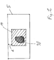
- the second radiation source 18a can, for example, emit a heating beam 18c, which by means of the deflection device 18b can be directed onto any partial surfaces 19 of the construction field 5 (cf. Fig. 2 ) bounded by the container wall 1a can be steered.
- the second radiation source 18a can either generate electromagnetic radiation, that is to say in particular be a laser, or generate particle radiation (eg electrons). In the latter case
- deflector 18b would be ion optics.
- the heating beam 18c is a laser beam
- the second radiation source 18a can optionally be dispensed with, and instead the first radiation source 6 can be used to generate the heating beam 18c. This is then done by means of a in Fig. 1 Not shown additional optics expediently reduces the light intensity compared to the light intensity of the solidification beam 7.
- the amount of heat introduced by the heating jet 18c can also be adjusted by the speed with which it is moved over the applied layer of the building material.
- the device 100 includes a control unit 10, via which the individual components of the device 100 are controlled in a coordinated manner for carrying out the construction process.
- the control unit may include a CPU whose operation is controlled by a computer program (software).
- the computer program can be stored separately from the device on a storage medium, from which it can be loaded into the device, in particular into the control unit 10.
- the deflecting device 18b is designed such that the heating beam 18c of the second radiation source 18a can be directed to any areas of the building field 5, in particular directed onto only one or more partial surfaces 19 thereof, wherein the total area of all partial areas 19 and in particular the area of a partial area 19 is smaller than the area of the construction field 5.
- the introduced heat energy can be adjusted by changing the power density at the point of impact of the heating beam 18c on the construction field 5 and / or by changing the scanning speed of the heating beam 18c.
- the heater 18a is dimensioned that, if necessary, by sufficient focusing of the heating jet 18c and / or sufficiently slow movement of the heating jet 18c over the building field 5, at least as much energy can be introduced into the optionally already partially solidified topmost powder layer that the temperature at the impingement point of the heating jet 18c is significantly higher than in other areas of the construction field 5.
- significantly higher is preferably meant that the temperature of the powdered building material at the point of impact of the heating jet 18c at least 300 ° C, preferably at least 400 ° C and in some cases at least 800 ° C above the temperature of Building material in areas of the construction field 5 is located in which no object cross section of the object to be produced, usually in an edge region of the construction field fifth
- Activation temperature is understood here as meaning a temperature at which the powder particles combine with one another as a result of a chemical and / or physical change in their properties, for example by the powder particles completely melting or merely superficially melting and sintering together.
- the activation temperature is therefore a limit temperature at which the building material is substantially modified in its chemical and / or physical structure.
- control software in the control device 10 controls the heating jet 18c in such a way that the point of impact of the heating jet on the construction field 5 always maintains a minimum distance d from the edge of the construction field 5.
- This situation is in Fig. 2 shown.
- an object cross-section 30 to be solidified is shown within the construction field 5, which is covered by a partial surface 19 in which heating of the construction material takes place by means of the heating beam 18c.
- the edge of the partial surface 19 has a minimum distance d from the edge of the construction field 5.
- the heat dissipation properties of the building material used in each case it can be specifically determined to which plateau temperature the powdery building material should be preheated.
- the minimum distance d to the edge of the construction field 5 is also influenced by the heat transfer properties of the powder. As mentioned above, the powder within this distance is to provide insulation to the outside of the construction field 5. Thus, the better the heat transfer properties of the unconsolidated powdery building material, the greater the minimum distance d should be selected.
- control unit 10 has a data memory in which material parameter values relating to the heat transfer properties of the building material to be used in a planned production of one or more objects are stored. In a manufacturing process, the control unit 10 may then perform the control of the selective heating device 18a, 18b taking into account these material parameter values.
- material parameters or material parameter values relating to a plurality of construction materials are stored in the data memory, so that only the type of building material used must be communicated to the control unit 10 before the beginning of a construction process.
- the heat transfer capacity of the building material is determined in preliminary tests in order to be taken into account in determining the plateau temperature and the minimum distance d.
- the needle probe method For the determination of the thermal conductivity of powdery materials, first the needle probe method according to ASTM D5334-08 is recommended.
- an elongated thin heat source (the needle probe) is placed in a powder bed and heated with constant power. At the same time, the temperature inside the source is registered. The slower the source temperature rises, the higher the thermal conductivity of the sample material.
- Fig. 3 shows enlarged the container 1 of the device 100 together with the support plate 2 arranged therein.
- a heat-insulating pad 32 is mounted, on which a heating cylinder 33 and a measuring rod 34 with a defined distance ⁇ are attached to the heating cylinder 33.
- the entire container 1 is filled with building material 13 up to a filling level Z, which coincides with the height of the heating cylinder 33.
- the heating cylinder 33 for example, by an inductive heating, preheated to a temperature Tv, which is for example at 100 ° C below the target in the subsequent actual construction activation temperature for the building material 13.
- a temperature Tv which is for example at 100 ° C below the target in the subsequent actual construction activation temperature for the building material 13.
- temperature sensing elements 35 are mounted at different heights. In the Fig. 3 however, exactly three of these elements are shown, but any other number of temperature sensing elements may be used as well.
- the temperature is detected with the temperature detecting elements 35 as a function of time. The Time change of the temperature is dependent on the heat transfer properties of the building material 13 in space with the distance ⁇ between the measuring rod 34 and the heating cylinder 33rd
- a plurality of measuring rods 34 can also be arranged at different distances ⁇ 1 ... ⁇ n from the heating element 33.
- the heating element 33 may, for example, be a cylinder whose height substantially coincides with the height of the most solid object produced in the subsequent construction process or whose diameter substantially coincides with the maximum diameter parallel to the support plate 2 of the most solid object produced in the subsequent construction process.
- the thermal conductivity of the building material can also be determined during the production process of objects.
- the temperature of the uppermost powder layer is measured at different locations by means of a thermal imaging camera (IR camera) or a point pyrometer whose detection surface is moved over the uppermost powder layer. Since it is known at which points of the powder layer, a solidification is carried out with the hardening beam 7 and / or a preheating with the heating beam 18c is performed, it can be based on the distances between the locations of the powder layer, where the temperature was determined to the points the powder layer, where energy is supplied, gain information about the heat transfer capability of the powder.
- IR camera thermal imaging camera
- a point pyrometer whose detection surface is moved over the uppermost powder layer. Since it is known at which points of the powder layer, a solidification is carried out with the hardening beam 7 and / or a preheating with the heating beam 18c is performed, it can be based on the distances between the locations of the powder layer, where the temperature was determined to the points the powder layer, where energy is supplied, gain information about the heat transfer capability of the powder.
- the minimum distance d to the field edge can also be adjusted as a function of the measured values obtained become.
- the temperature at the reference location can alternatively or additionally be used for controlling the heat input into the at least one partial area 19 by the selective heating device, so that a minimum plateau temperature to which the partial area 19 of the building area 5 is heated by a predetermined amount is above a temperature transmitted from the temperature measuring device to the control unit 10.
- the minimum plateau temperature is preferably at least 300 ° C., more preferably at least 400 ° C., particularly preferably at least 800 ° C. above the temperature transmitted by the temperature measuring device to the control unit 10.
- the container preferably the container wall, be provided with a heating and / or cooling device (not shown).
- a heater at this point allows additional heating of the building material, so that not so much heat must be entered by the heating beam 18c.
- a cooling device in the wall of the container 1 causes the temperature outside the container 1 to be prevented from rising too high. If you tune the heating power of the heating beam 18c, the minimum distance d and the cooling capacity of the cooling for the container, so you can reach a steady temperature distribution.
- the invention is also applicable to other apparatus for manufacturing three-dimensional objects by the action of an energy beam for solidifying a powdery building material.
- the energy for solidifying the powder may also be spread over a planar radiation source, e.g. an infrared heater, are introduced.
- a planar radiation source e.g. an infrared heater
- the radiation for solidifying the building material is not restricted to electromagnetic radiation. Rather, it is also possible to use particle radiation, for example an electron beam.
- the supply of energy with the heating jet can not only be applied to a solidifying process before the beginning of a solidification process Powder layer happen, but also simultaneously with the solidification process.
- the selective heating device By heating with the selective heating device, it is desirable to reduce the cooling rate in the partial area or surfaces 19 by at least 30%, preferably at least 50%, particularly preferably at least 70%, than without the action of the selective heating device 18a, 18b Case would be.
- the entire powder layer within the construction field 5 can be preheated additionally with a non-selective surface heating to a starting temperature, which is for example at 150 ° C.
- not only one object can be manufactured in a manufacturing process, but also several objects in the container 1 can be produced in parallel. If an object is referred to earlier, for example a selective heating of an object cross-section, then this procedure can also be applied to all other objects to be produced in the production process. For example, in the case of a plurality of object cross sections in a powder layer, the powder would be selectively heated in the region of a plurality of object cross sections, preferably all.
- selective heating preferably makes sense in those partial areas 19 which are almost identical to the object cross-section (s) to be solidified in a freshly applied powder layer.
- the partial area or areas 19 to be heated with the selective heating device preferably vary from layer to layer.
- different partial areas 19 in a freshly applied layer (which need not necessarily be assigned to the cross sections of different objects) need not necessarily be brought to the same plateau temperature.
- a selective heating of partial surfaces 19 of a powder layer applied takes place such that around each selectively heated partial surface 19 there is a non-selectively heated powder layer which has at least one lateral extension d perpendicular to the edge of the partial surface 19.
- a non-selectively heated powder layer which has at least one lateral extension d perpendicular to the edge of the partial surface 19.
- the method according to the invention and the device according to the invention are particularly suitable for metallic building materials.
- the procedure according to the invention also brings advantages, if other building materials, such as ceramic or plastic powder, in particular a PAEK powder, are used
Claims (15)
- Dispositif (100) destiné à fabriquer un objet tridimensionnel (3) par solidification couche par couche d'un matériau de construction (11) pulvérulent au moyen d'un rayonnement électromagnétique ou d'un rayonnement de particules, comportant :un support réglable en hauteur (2), sur lequel est monté l'objet (3) et dont l'extension horizontale définit un champ de construction (5),un dispositif d'irradiation (6, 9) destiné à orienter le rayonnement électromagnétique ou le rayonnement de particules sur des zones d'une couche du matériau de construction appliquée à l'intérieur du champ de construction (5) correspondant à une section transversale d'objet (30),une unité de commande (10) destinée à commander le dispositif d'irradiation (6, 9) de manière à ce que les particules de poudre du matériau de construction (11) se lient les unes aux autres aux endroits où le rayonnement électromagnétique ou le rayonnement de particules impacte le matériau de construction,caractérisé par un dispositif de chauffage sélectif (18a, 18b), qui est conçu pour pouvoir chauffer une surface partielle (19) quelconque du champ de construction (5) à une température de plateau, laquelle température de plateau est significativement supérieure à une température d'au moins une zone du champ de construction (5) située à l'extérieur de la surface partielle (19), dans lequel l'unité de commande (10) est conçue pour actionner le dispositif de chauffage sélectif (18a, 18b) de manière à ce que la surface partielle (19) présente une distance minimale prédéfinie (d) par rapport à la périphérie du champ de construction (5).
- Dispositif selon la revendication 1, dans lequel la température de plateau est au maximum de 200°C, préférablement au maximum de 150°C, et de manière particulièrement préférable au maximum de 100°C, inférieure à une température d'activation du matériau de construction (11).
- Dispositif selon la revendication 1 ou 2, dans lequel
l'unité de commande (10) comporte une mémoire de données, dans laquelle sont stockées des valeurs de paramètres de matériaux concernant un comportement thermique d'au moins un matériau de construction, de préférence de matériaux de construction différents. - Dispositif selon la revendication 3, dans lequel l'unité de commande, lors du fonctionnement, fixe la distance minimale (d) en fonction des valeurs de paramètres de matériau qui sont stockées dans la mémoire de données pour le matériau de construction (11) utilisé.
- Dispositif selon l'une des revendications 1 à 4, dans lequel l'unité de commande (10), lors du fonctionnement, détermine la forme de la surface partielle (19) en fonction de la forme de la section transversale d'objet (30) à solidifier.
- Dispositif selon l'une des revendications 1 à 5, dans lequel l'unité de commande (10), lors du fonctionnement, détermine la surface partielle (19) de manière à ce que sa superficie soit supérieure à celle de la section transversale d'objet (30) à solidifier.
- Dispositif selon l'une des revendications 1 à 6, dans lequel le dispositif de chauffage sélectif (18a, 18b), lors du fonctionnement, oriente un rayonnement électromagnétique, notamment un rayonnement laser (18c), et/ou un rayonnement de particules, sur la surface du matériau de construction (11).
- Dispositif selon la revendication 7, dans lequel le dispositif d'irradiation (6, 9) oriente un rayonnement laser (7) sur la surface du matériau de construction (11) et le rayonnement laser (18c) du dispositif de chauffage sélectif (18a, 18b) présente la même longueur d'onde que celle du dispositif d'irradiation (6, 9).
- Dispositif selon l'une des revendications 1 à 8, comportant en outre un récipient (1) qui entoure le champ de construction (5), dans lequel le dispositif comprend un dispositif de refroidissement et/ou de chauffage pour refroidir et/ou chauffer le récipient (1).
- Dispositif selon l'une des revendications 1 à 9, comportant un système de mesure de température, de préférence à la périphérie du champ de construction (5), dans lequel l'unité de commande (10), lors du fonctionnement, contrôle l'apport de chaleur par le dispositif de chauffage sélectif (18a, 18b) de manière à ce qu'une température de plateau minimale à laquelle la surface partielle (19) du champ de construction est chauffée soit, dans au moins un état de fonctionnement, supérieure d'une valeur prédéterminée à une température transmise par le système de mesure de température à l'unité de commande (10).
- Dispositif selon la revendication 10, dans lequel l'unité de commande (10) actionne le dispositif de chauffage sélectif de manière à ce que la surface partielle (19) soit préchauffée à une température de plateau minimale qui est supérieure d'au moins 300°C, préférablement d'au moins 400°C, et de manière particulièrement préférable d'au moins 800°C, à la température transmise à l'unité de commande (10) par le système de mesure de température.
- Dispositif selon l'une des revendications 1 à 11, dans lequel l'unité de commande (10) actionne le dispositif de chauffage sélectif (18a, 18b) de manière à ce que ce dernier, après l'orientation du rayonnement électromagnétique ou du rayonnement de particules sur le matériau de construction au moyen du dispositif d'irradiation (6, 9), chauffe une surface partielle (19) du champ de construction (5) de sorte qu'une vitesse de refroidissement dans la surface partielle (19) soit inférieure d'au moins 30 %, préférablement d'au moins 50 %, et de manière particulièrement préférable d'au moins 70 %, à celle obtenue sans l'effet du dispositif de chauffage sélectif (18a, 18b), dans lequel la surface partielle (19) présente une distance minimale prédéfinie (d) par rapport à la périphérie du champ de construction (5).
- Procédé de fabrication d'un objet tridimensionnel (3) par solidification couche par couche d'un matériau de construction (11) pulvérulent au moyen d'un rayonnement électromagnétique ou d'un rayonnement de particules dans un dispositif (100), notamment selon les revendications 1 à 12,
dans lequel un objet (3) est monté sur un support réglable en hauteur (2), dont l'extension horizontale définit un champ de construction (5),
dans lequel le rayonnement électromagnétique ou le rayonnement de particules est orienté à l'aide d'un dispositif d'irradiation (6, 9) sur des zones d'une couche du matériau de construction appliquée à l'intérieur du champ de construction (5) correspondant à une section transversale d'objet (30).
dans lequel le dispositif d'irradiation (6, 9) est actionné par une unité de commande (10) de manière à ce que les particules de poudre du matériau de construction (11) se lient les unes aux autres aux endroits où le rayonnement électromagnétique ou le rayonnement de particules impacte le matériau de construction,
caractérisé en ce qu'une surface partielle (19) quelconque du champ de construction (5) est chauffée par un dispositif de chauffage sélectif (18a, 18b) à une température de plateau, laquelle température de plateau est significativement supérieure à une température d'au moins une zone du champ de construction (5) située à l'extérieur de la surface partielle (19), dans lequel l'unité de commande (10) actionne le dispositif de chauffage sélectif (18a, 18b) de sorte que la surface partielle (19) présente une distance minimale prédéfinie (d) par rapport à la périphérie du champ de construction (5). - Procédé selon la revendication 13, dans lequel la distance minimale (d) est fixée en fonction d'essais préliminaires, au cours desquels la capacité de transfert thermique du matériau de construction (11) utilisé dans le procédé est déterminée.
- Procédé selon l'une des revendications 13 ou 14, dans lequel l'unité de commande (10) actionne le dispositif de chauffage sélectif (18a, 18b) de manière à ce que ce dernier chauffe la surface partielle (19) du champ de construction (5) au moins à la température de plateau, avant et/ou après l'orientation du rayonnement électromagnétique ou du rayonnement de particules sur le matériau de construction au moyen du dispositif d'irradiation (6, 9), dans lequel la surface partielle (19) présente une distance minimale prédéfinie (d) par rapport à la périphérie du champ de construction (5).
Applications Claiming Priority (1)
| Application Number | Priority Date | Filing Date | Title |
|---|---|---|---|
| DE102015202964.6A DE102015202964A1 (de) | 2015-02-18 | 2015-02-18 | Vorrichtung und Verfahren zum Herstellen eines dreidimensionalen Objekts |
Publications (2)
| Publication Number | Publication Date |
|---|---|
| EP3059076A1 EP3059076A1 (fr) | 2016-08-24 |
| EP3059076B1 true EP3059076B1 (fr) | 2018-04-04 |
Family
ID=55527242
Family Applications (1)
| Application Number | Title | Priority Date | Filing Date |
|---|---|---|---|
| EP16155718.6A Active EP3059076B1 (fr) | 2015-02-18 | 2016-02-15 | Procede et dispositif destines a fabriquer un objet tridimensionnel |
Country Status (4)
| Country | Link |
|---|---|
| US (2) | US20160236299A1 (fr) |
| EP (1) | EP3059076B1 (fr) |
| CN (1) | CN105881896B (fr) |
| DE (1) | DE102015202964A1 (fr) |
Families Citing this family (19)
| Publication number | Priority date | Publication date | Assignee | Title |
|---|---|---|---|---|
| DE102011087374A1 (de) * | 2011-11-29 | 2013-05-29 | Matthias Fockele | Verfahren zur Herstellung eines Formkörpers durch schichtweises Aufbauen aus Werkstoffpulver |
| TWI582885B (zh) * | 2015-12-30 | 2017-05-11 | 國立中央大學 | 低溫製造組織工程用支架的平台結構及低溫製造組織工程用支架的製造方法 |
| CN109070452B (zh) * | 2016-05-12 | 2021-06-22 | 惠普发展公司,有限责任合伙企业 | 增材制造系统和用于后处理的方法 |
| US10457033B2 (en) | 2016-11-07 | 2019-10-29 | The Boeing Company | Systems and methods for additively manufacturing composite parts |
| US11440261B2 (en) * | 2016-11-08 | 2022-09-13 | The Boeing Company | Systems and methods for thermal control of additive manufacturing |
| US10766241B2 (en) | 2016-11-18 | 2020-09-08 | The Boeing Company | Systems and methods for additive manufacturing |
| US10843452B2 (en) | 2016-12-01 | 2020-11-24 | The Boeing Company | Systems and methods for cure control of additive manufacturing |
| CN106825567B (zh) * | 2017-01-22 | 2018-12-11 | 清华大学 | 电子束选区熔化与电子束切割复合的增材制造方法 |
| DE102017104506A1 (de) * | 2017-03-03 | 2018-09-06 | Cl Schutzrechtsverwaltungs Gmbh | Vorrichtung zur additiven Herstellung dreidimensionaler Objekte |
| DE102017105056A1 (de) * | 2017-03-09 | 2018-09-13 | Cl Schutzrechtsverwaltungs Gmbh | Vorrichtung zur additiven Herstellung dreidimensionaler Objekte |
| EP3446855B1 (fr) * | 2017-08-25 | 2021-11-24 | CL Schutzrechtsverwaltungs GmbH | Appareil de fabrication additive d'objets tridimensionnels |
| DE102018100508A1 (de) * | 2017-10-18 | 2019-04-18 | Value & Intellectual Properties Management Gmbh | 3D-Schmelzdruckverfahren |
| DE102017124424A1 (de) * | 2017-10-19 | 2019-04-25 | Trumpf Laser- Und Systemtechnik Gmbh | Hubeinrichtung für einen Bauzylinder in einer Maschine, Maschine zur Herstellung von dreidimensionalen Bauteilen mit einer Hubeinrichtung sowie Verfahren zur Ansteuerung der Hubeinrichtung |
| US20200238617A1 (en) * | 2017-10-20 | 2020-07-30 | Hewlett-Packard Development Company, L.P. | Apparatuses with a porous membrane to fluidize particulate material |
| CN107914399B (zh) * | 2017-12-14 | 2021-10-26 | 徐素香 | 一种产品脱层检测系统 |
| EP3501695A1 (fr) * | 2017-12-22 | 2019-06-26 | Evonik Degussa GmbH | Dispositif de fabrication en couche d'objets tridimensionnels et procédé |
| CN112218735B (zh) * | 2018-04-06 | 2022-11-11 | 帕克西斯有限责任公司 | 增材制造装置、系统和方法 |
| US11167375B2 (en) | 2018-08-10 | 2021-11-09 | The Research Foundation For The State University Of New York | Additive manufacturing processes and additively manufactured products |
| GB201918601D0 (en) | 2019-12-17 | 2020-01-29 | Renishaw Plc | Powder bed fusion additive manufacturing methods and apparatus |
Citations (8)
| Publication number | Priority date | Publication date | Assignee | Title |
|---|---|---|---|---|
| US5508489A (en) | 1993-10-20 | 1996-04-16 | United Technologies Corporation | Apparatus for multiple beam laser sintering |
| US6007764A (en) | 1998-03-27 | 1999-12-28 | United Technologies Corporation | Absorption tailored laser sintering |
| DE102005048314A1 (de) | 2005-10-06 | 2007-04-19 | Laserinstitut Mittelsachsen E.V. | Verfahren und Vorrichtung zum selektiven Lasersintern |
| DE102007024469A1 (de) | 2007-05-25 | 2008-11-27 | Eos Gmbh Electro Optical Systems | Verfahren zum schichtweisen Herstellen eines dreidimensionalen Objekts |
| US20100007062A1 (en) | 2006-07-27 | 2010-01-14 | Arcam Ab | Method and device for producing three-dimensional objects |
| FR2984778A1 (fr) | 2011-12-23 | 2013-06-28 | Michelin Soc Tech | Procede et appareil pour realiser des objets tridimensionnels |
| DE102012012344A1 (de) | 2012-03-21 | 2013-09-26 | Fraunhofer-Gesellschaft zur Förderung der angewandten Forschung e.V. | Verfahren und Vorrichtung zur Herstellung von Werkstücken durch Strahlschmelzen pulverförmigen Materials |
| EP2292357B1 (fr) | 2009-08-10 | 2016-04-06 | BEGO Bremer Goldschlägerei Wilh.-Herbst GmbH & Co KG | Article céramique et procédés de production de cet article |
Family Cites Families (15)
| Publication number | Priority date | Publication date | Assignee | Title |
|---|---|---|---|---|
| DE10105504A1 (de) * | 2001-02-07 | 2002-08-14 | Eos Electro Optical Syst | Vorrichtung zur Behandlung von Pulver für eine Vorrichtung zum Herstellen eines dreidimensionalen Objekts, Vorrichtung zum Herstellen eines dreidimensionalen Objekts und Verfahren zum Herstellen eines dreidimensionalen Objekts |
| DE10236697A1 (de) | 2002-08-09 | 2004-02-26 | Eos Gmbh Electro Optical Systems | Verfahren und Vorrichtung zur Herstellung eines dreidimensionalen Objekts mittels Sintern |
| SE524420C2 (sv) | 2002-12-19 | 2004-08-10 | Arcam Ab | Anordning samt metod för framställande av en tredimensionell produkt |
| DE102004009127A1 (de) * | 2004-02-25 | 2005-09-15 | Bego Medical Ag | Verfahren und Vorrichtung zum Herstellen von Produkten durch Sintern und/oder Schmelzen |
| DE102005015870B3 (de) | 2005-04-06 | 2006-10-26 | Eos Gmbh Electro Optical Systems | Vorrichtung und Verfahren zum Herstellen eines dreidimensionalen Objekts |
| DE102005024790A1 (de) * | 2005-05-26 | 2006-12-07 | Eos Gmbh Electro Optical Systems | Strahlungsheizung zum Heizen des Aufbaumaterials in einer Lasersintervorrichtung |
| US9895842B2 (en) * | 2008-05-20 | 2018-02-20 | Eos Gmbh Electro Optical Systems | Selective sintering of structurally modified polymers |
| DE102008060046A1 (de) * | 2008-12-02 | 2010-06-10 | Eos Gmbh Electro Optical Systems | Verfahren zum Bereitstellen einer identifizierbaren Pulvermenge und Verfahren zur Herstellung eines Objekts |
| DE102010004036A1 (de) * | 2010-01-05 | 2011-07-07 | EOS GmbH Electro Optical Systems, 82152 | Vorrichtung zum generativen Herstellen eines dreidimensionalen Objekts mit kontinuierlicher Wärmezufuhr |
| DE102010008960A1 (de) * | 2010-02-23 | 2011-08-25 | EOS GmbH Electro Optical Systems, 82152 | Verfahren und Vorrichtung zum Herstellen eines dreidimensionalen Objekts, das sich insbesondere für den Einsatz in der Mikrotechnik eignet |
| FR2984779B1 (fr) * | 2011-12-23 | 2015-06-19 | Michelin Soc Tech | Procede et appareil pour realiser des objets tridimensionnels |
| DE102012212587A1 (de) | 2012-07-18 | 2014-01-23 | Eos Gmbh Electro Optical Systems | Vorrichtung und Verfahren zum schichtweisen Herstellen eines dreidimensionalen Objekts |
| DE102013208651A1 (de) * | 2013-05-10 | 2014-11-13 | Eos Gmbh Electro Optical Systems | Verfahren zum automatischen Kalibrieren einer Vorrichtung zum generativen Herstellen eines dreidimensionalen Objekts |
| DE102013213547A1 (de) * | 2013-07-10 | 2015-01-15 | Eos Gmbh Electro Optical Systems | Kalibriereinrichtung und Kalibrierverfahren für eine Vorrichtung zum schichtweisen Herstellen eines Objekts |
| US20160016255A1 (en) * | 2014-07-17 | 2016-01-21 | Siemens Energy, Inc. | Laser correction of metal deformation |
-
2015
- 2015-02-18 DE DE102015202964.6A patent/DE102015202964A1/de active Pending
-
2016
- 2016-02-11 US US15/041,695 patent/US20160236299A1/en not_active Abandoned
- 2016-02-15 EP EP16155718.6A patent/EP3059076B1/fr active Active
- 2016-02-18 CN CN201610090294.0A patent/CN105881896B/zh active Active
-
2021
- 2021-11-15 US US17/454,934 patent/US11752697B2/en active Active
Patent Citations (8)
| Publication number | Priority date | Publication date | Assignee | Title |
|---|---|---|---|---|
| US5508489A (en) | 1993-10-20 | 1996-04-16 | United Technologies Corporation | Apparatus for multiple beam laser sintering |
| US6007764A (en) | 1998-03-27 | 1999-12-28 | United Technologies Corporation | Absorption tailored laser sintering |
| DE102005048314A1 (de) | 2005-10-06 | 2007-04-19 | Laserinstitut Mittelsachsen E.V. | Verfahren und Vorrichtung zum selektiven Lasersintern |
| US20100007062A1 (en) | 2006-07-27 | 2010-01-14 | Arcam Ab | Method and device for producing three-dimensional objects |
| DE102007024469A1 (de) | 2007-05-25 | 2008-11-27 | Eos Gmbh Electro Optical Systems | Verfahren zum schichtweisen Herstellen eines dreidimensionalen Objekts |
| EP2292357B1 (fr) | 2009-08-10 | 2016-04-06 | BEGO Bremer Goldschlägerei Wilh.-Herbst GmbH & Co KG | Article céramique et procédés de production de cet article |
| FR2984778A1 (fr) | 2011-12-23 | 2013-06-28 | Michelin Soc Tech | Procede et appareil pour realiser des objets tridimensionnels |
| DE102012012344A1 (de) | 2012-03-21 | 2013-09-26 | Fraunhofer-Gesellschaft zur Förderung der angewandten Forschung e.V. | Verfahren und Vorrichtung zur Herstellung von Werkstücken durch Strahlschmelzen pulverförmigen Materials |
Non-Patent Citations (5)
| Title |
|---|
| ABE ET AL.: "The manufacturing of hard tools from metallic powders by selective laser melting", JOURNAL OF MATERIALS PROCESSING TECHNOLOGY, vol. 111, 2001, pages 210 - 213, XP055546118 |
| J. DECKERS ET AL.: "Additive Manufacturing of Ceramics: A Review", JOURNAL OF CERAMIC SCIENCE AND TECHNOLOGY, vol. 05, no. 04, 2014, pages 245 - 260, XP055546095 |
| P. AGGARANGSI ET AL.: "Localized preheating approaches for reducing residual stress in additive manufacturing", CARNEGIE MELLON UNIVERSITY, 2006, pages 709 - 720, XP055546112, Retrieved from the Internet <URL:https://www.researchgate.net/publication/268402375_Localized_Preheating_Ap proaches_for_Reducing_Residual_Stress_in_Additive_Manufacturing?enrichld =rgreq-6e928369fca61690207 ab01943eda3dd- XXX&enrichSource=Y292ZXJQYWdlOzl2ODQwMjM3NTtBUzozMTUwNzg5Njc wMDUxODRAMTQ1MjEzMjA4NzM1OQ%3D%3D&el=1_x_2&_esc=p> |
| RAFI ET AL.: "Microstructures and Mechanical Properties of Ti6AI4V Parts Fabricated by Selective Laser Melting and Electron Beam Melting", JOURNAL OF MATERIALS ENGINEERING AND PERFORMANCE, vol. 22, no. 12, December 2013 (2013-12-01), pages 3872 - 3883, XP055546130 |
| WILKES ET AL.: "Additive manufacturing of Zr02-AI203 ceramic components by selective laser melting", RAPID PROTOTYPING JOURNAL, 2013, pages 51 - 57, XP055546135 |
Also Published As
| Publication number | Publication date |
|---|---|
| US11752697B2 (en) | 2023-09-12 |
| DE102015202964A1 (de) | 2016-08-18 |
| CN105881896A (zh) | 2016-08-24 |
| US20160236299A1 (en) | 2016-08-18 |
| EP3059076A1 (fr) | 2016-08-24 |
| US20220072615A1 (en) | 2022-03-10 |
| CN105881896B (zh) | 2019-12-17 |
Similar Documents
| Publication | Publication Date | Title |
|---|---|---|
| EP3059076B1 (fr) | Procede et dispositif destines a fabriquer un objet tridimensionnel | |
| EP3099469B1 (fr) | Procédé et dispositif de commande améliorée de l'apport d'énergie dans un procédé de construction additive par génération de couches | |
| EP3434450B1 (fr) | Procédé et dispositif de fabrication d'un composant tridimensionnel | |
| EP2340925B1 (fr) | Procédé de fabrication générative d'un objet tridimensionnel doté d'une amenée de chaleur en continu | |
| EP3077180B1 (fr) | Procédé de production accélérée d'objets par fabrication générative | |
| EP0759848B1 (fr) | Procede et dispositif permettant de produire un objet en trois dimensions par frittage au laser | |
| EP3318352A1 (fr) | Procédé de détection basé sur la simulation de zones de composants thermiquement critiques et procédé d'adaptation spécifique aux composants d'une génération de chaleur locale lors de la fabrication additive | |
| EP3263317B1 (fr) | Dispositif et procédé de commande de rayonnement dans un dispositif de fabrication d'un objet tridimensionnel | |
| EP3260276A1 (fr) | Ajustement automatique d'un réglage de chauffage dans un dispositif de fabrication additive | |
| DE102017207264A1 (de) | Homogenisierung des Energieeintrags | |
| DE102018202506A1 (de) | Additives Herstellverfahren mit kontrollierter Verfestigung und zugehörige Vorrichtung | |
| EP3579996A1 (fr) | Stratégie d'exposition dans des systèmes de fabrication additive (am) à faisceaux multiples | |
| DE102017130282A1 (de) | Verfahren und Vorrichtung zum additiven Herstellen eines Bauteil sowie Bauteil | |
| DE102016203955A1 (de) | Generatives Schichtbauverfahren mit verbesserter Detailauflösung und Vorrichtung zur Durchführung desselben | |
| EP3710183A1 (fr) | Tri de bandes d'irradiation | |
| DE102018204510A1 (de) | Computerbasiertes Verfahren zum Bereitstellen von Steuerbefehlsdaten für eine additive Herstellvorrichtung | |
| DE102017207832A1 (de) | Positionsspezifischer Energieeintrag | |
| DE102018200721A1 (de) | Verfahren zur Ermittlung von Daten zur verbesserten Steuerung einer Vorrichtung zur Herstellung von Gegenständen nach der Methode des selektiven Pulverschmelzens sowie Vorrichtung dazu | |
| DE102018205689A1 (de) | Verfahren und Vorrichtung zur Verbesserung der Bauteilhomogenität von durch ein additives Herstellverfahren hergestellten Objekten | |
| WO2020058114A1 (fr) | Calcul de trajets d'exposition à faible distorsion des pièces | |
| WO2021074188A1 (fr) | Procédé de fonctionnement d'un dispositif de fabrication additive d'un objet tridimensionnel et procédé de création d'une fenêtre de traitement pour mettre en œuvre ledit procédé | |
| WO2019201498A1 (fr) | Post-exposition sélective | |
| DE102018205688A1 (de) | Verfahren und Vorrichtung zur Verbesserung der Bauteilqualität von durch ein additives Herstellverfahren hergestellten Objekten | |
| DE102016212171A1 (de) | Generatives Schichtbauverfahren und zugehörige Vorrichtung zur Herstellung von Objekten mit verminderter Porosität |
Legal Events
| Date | Code | Title | Description |
|---|---|---|---|
| PUAI | Public reference made under article 153(3) epc to a published international application that has entered the european phase |
Free format text: ORIGINAL CODE: 0009012 |
|
| AK | Designated contracting states |
Kind code of ref document: A1 Designated state(s): AL AT BE BG CH CY CZ DE DK EE ES FI FR GB GR HR HU IE IS IT LI LT LU LV MC MK MT NL NO PL PT RO RS SE SI SK SM TR |
|
| AX | Request for extension of the european patent |
Extension state: BA ME |
|
| STAA | Information on the status of an ep patent application or granted ep patent |
Free format text: STATUS: REQUEST FOR EXAMINATION WAS MADE |
|
| 17P | Request for examination filed |
Effective date: 20170208 |
|
| RBV | Designated contracting states (corrected) |
Designated state(s): AL AT BE BG CH CY CZ DE DK EE ES FI FR GB GR HR HU IE IS IT LI LT LU LV MC MK MT NL NO PL PT RO RS SE SI SK SM TR |
|
| GRAP | Despatch of communication of intention to grant a patent |
Free format text: ORIGINAL CODE: EPIDOSNIGR1 |
|
| STAA | Information on the status of an ep patent application or granted ep patent |
Free format text: STATUS: GRANT OF PATENT IS INTENDED |
|
| INTG | Intention to grant announced |
Effective date: 20170831 |
|
| GRAS | Grant fee paid |
Free format text: ORIGINAL CODE: EPIDOSNIGR3 |
|
| GRAA | (expected) grant |
Free format text: ORIGINAL CODE: 0009210 |
|
| STAA | Information on the status of an ep patent application or granted ep patent |
Free format text: STATUS: THE PATENT HAS BEEN GRANTED |
|
| AK | Designated contracting states |
Kind code of ref document: B1 Designated state(s): AL AT BE BG CH CY CZ DE DK EE ES FI FR GB GR HR HU IE IS IT LI LT LU LV MC MK MT NL NO PL PT RO RS SE SI SK SM TR |
|
| REG | Reference to a national code |
Ref country code: GB Ref legal event code: FG4D Free format text: NOT ENGLISH |
|
| REG | Reference to a national code |
Ref country code: CH Ref legal event code: EP |
|
| REG | Reference to a national code |
Ref country code: AT Ref legal event code: REF Ref document number: 985147 Country of ref document: AT Kind code of ref document: T Effective date: 20180415 |
|
| REG | Reference to a national code |
Ref country code: IE Ref legal event code: FG4D Free format text: LANGUAGE OF EP DOCUMENT: GERMAN |
|
| REG | Reference to a national code |
Ref country code: DE Ref legal event code: R096 Ref document number: 502016000808 Country of ref document: DE |
|
| REG | Reference to a national code |
Ref country code: NL Ref legal event code: MP Effective date: 20180404 |
|
| REG | Reference to a national code |
Ref country code: LT Ref legal event code: MG4D |
|
| PG25 | Lapsed in a contracting state [announced via postgrant information from national office to epo] |
Ref country code: NL Free format text: LAPSE BECAUSE OF FAILURE TO SUBMIT A TRANSLATION OF THE DESCRIPTION OR TO PAY THE FEE WITHIN THE PRESCRIBED TIME-LIMIT Effective date: 20180404 |
|
| PG25 | Lapsed in a contracting state [announced via postgrant information from national office to epo] |
Ref country code: PL Free format text: LAPSE BECAUSE OF FAILURE TO SUBMIT A TRANSLATION OF THE DESCRIPTION OR TO PAY THE FEE WITHIN THE PRESCRIBED TIME-LIMIT Effective date: 20180404 Ref country code: LT Free format text: LAPSE BECAUSE OF FAILURE TO SUBMIT A TRANSLATION OF THE DESCRIPTION OR TO PAY THE FEE WITHIN THE PRESCRIBED TIME-LIMIT Effective date: 20180404 Ref country code: SE Free format text: LAPSE BECAUSE OF FAILURE TO SUBMIT A TRANSLATION OF THE DESCRIPTION OR TO PAY THE FEE WITHIN THE PRESCRIBED TIME-LIMIT Effective date: 20180404 Ref country code: NO Free format text: LAPSE BECAUSE OF FAILURE TO SUBMIT A TRANSLATION OF THE DESCRIPTION OR TO PAY THE FEE WITHIN THE PRESCRIBED TIME-LIMIT Effective date: 20180704 Ref country code: ES Free format text: LAPSE BECAUSE OF FAILURE TO SUBMIT A TRANSLATION OF THE DESCRIPTION OR TO PAY THE FEE WITHIN THE PRESCRIBED TIME-LIMIT Effective date: 20180404 Ref country code: AL Free format text: LAPSE BECAUSE OF FAILURE TO SUBMIT A TRANSLATION OF THE DESCRIPTION OR TO PAY THE FEE WITHIN THE PRESCRIBED TIME-LIMIT Effective date: 20180404 Ref country code: FI Free format text: LAPSE BECAUSE OF FAILURE TO SUBMIT A TRANSLATION OF THE DESCRIPTION OR TO PAY THE FEE WITHIN THE PRESCRIBED TIME-LIMIT Effective date: 20180404 Ref country code: BG Free format text: LAPSE BECAUSE OF FAILURE TO SUBMIT A TRANSLATION OF THE DESCRIPTION OR TO PAY THE FEE WITHIN THE PRESCRIBED TIME-LIMIT Effective date: 20180704 |
|
| PG25 | Lapsed in a contracting state [announced via postgrant information from national office to epo] |
Ref country code: RS Free format text: LAPSE BECAUSE OF FAILURE TO SUBMIT A TRANSLATION OF THE DESCRIPTION OR TO PAY THE FEE WITHIN THE PRESCRIBED TIME-LIMIT Effective date: 20180404 Ref country code: HR Free format text: LAPSE BECAUSE OF FAILURE TO SUBMIT A TRANSLATION OF THE DESCRIPTION OR TO PAY THE FEE WITHIN THE PRESCRIBED TIME-LIMIT Effective date: 20180404 Ref country code: LV Free format text: LAPSE BECAUSE OF FAILURE TO SUBMIT A TRANSLATION OF THE DESCRIPTION OR TO PAY THE FEE WITHIN THE PRESCRIBED TIME-LIMIT Effective date: 20180404 Ref country code: GR Free format text: LAPSE BECAUSE OF FAILURE TO SUBMIT A TRANSLATION OF THE DESCRIPTION OR TO PAY THE FEE WITHIN THE PRESCRIBED TIME-LIMIT Effective date: 20180705 |
|
| PG25 | Lapsed in a contracting state [announced via postgrant information from national office to epo] |
Ref country code: PT Free format text: LAPSE BECAUSE OF FAILURE TO SUBMIT A TRANSLATION OF THE DESCRIPTION OR TO PAY THE FEE WITHIN THE PRESCRIBED TIME-LIMIT Effective date: 20180806 |
|
| REG | Reference to a national code |
Ref country code: DE Ref legal event code: R026 Ref document number: 502016000808 Country of ref document: DE |
|
| PLBI | Opposition filed |
Free format text: ORIGINAL CODE: 0009260 |
|
| PLAX | Notice of opposition and request to file observation + time limit sent |
Free format text: ORIGINAL CODE: EPIDOSNOBS2 |
|
| PG25 | Lapsed in a contracting state [announced via postgrant information from national office to epo] |
Ref country code: DK Free format text: LAPSE BECAUSE OF FAILURE TO SUBMIT A TRANSLATION OF THE DESCRIPTION OR TO PAY THE FEE WITHIN THE PRESCRIBED TIME-LIMIT Effective date: 20180404 Ref country code: SK Free format text: LAPSE BECAUSE OF FAILURE TO SUBMIT A TRANSLATION OF THE DESCRIPTION OR TO PAY THE FEE WITHIN THE PRESCRIBED TIME-LIMIT Effective date: 20180404 Ref country code: EE Free format text: LAPSE BECAUSE OF FAILURE TO SUBMIT A TRANSLATION OF THE DESCRIPTION OR TO PAY THE FEE WITHIN THE PRESCRIBED TIME-LIMIT Effective date: 20180404 Ref country code: RO Free format text: LAPSE BECAUSE OF FAILURE TO SUBMIT A TRANSLATION OF THE DESCRIPTION OR TO PAY THE FEE WITHIN THE PRESCRIBED TIME-LIMIT Effective date: 20180404 Ref country code: CZ Free format text: LAPSE BECAUSE OF FAILURE TO SUBMIT A TRANSLATION OF THE DESCRIPTION OR TO PAY THE FEE WITHIN THE PRESCRIBED TIME-LIMIT Effective date: 20180404 |
|
| 26 | Opposition filed |
Opponent name: ARCAM AB Effective date: 20190104 |
|
| PG25 | Lapsed in a contracting state [announced via postgrant information from national office to epo] |
Ref country code: SM Free format text: LAPSE BECAUSE OF FAILURE TO SUBMIT A TRANSLATION OF THE DESCRIPTION OR TO PAY THE FEE WITHIN THE PRESCRIBED TIME-LIMIT Effective date: 20180404 |
|
| PG25 | Lapsed in a contracting state [announced via postgrant information from national office to epo] |
Ref country code: SI Free format text: LAPSE BECAUSE OF FAILURE TO SUBMIT A TRANSLATION OF THE DESCRIPTION OR TO PAY THE FEE WITHIN THE PRESCRIBED TIME-LIMIT Effective date: 20180404 |
|
| PLBB | Reply of patent proprietor to notice(s) of opposition received |
Free format text: ORIGINAL CODE: EPIDOSNOBS3 |
|
| REG | Reference to a national code |
Ref country code: CH Ref legal event code: PL |
|
| PG25 | Lapsed in a contracting state [announced via postgrant information from national office to epo] |
Ref country code: LU Free format text: LAPSE BECAUSE OF NON-PAYMENT OF DUE FEES Effective date: 20190215 Ref country code: MC Free format text: LAPSE BECAUSE OF FAILURE TO SUBMIT A TRANSLATION OF THE DESCRIPTION OR TO PAY THE FEE WITHIN THE PRESCRIBED TIME-LIMIT Effective date: 20180404 |
|
| REG | Reference to a national code |
Ref country code: BE Ref legal event code: MM Effective date: 20190228 |
|
| REG | Reference to a national code |
Ref country code: IE Ref legal event code: MM4A |
|
| PG25 | Lapsed in a contracting state [announced via postgrant information from national office to epo] |
Ref country code: LI Free format text: LAPSE BECAUSE OF NON-PAYMENT OF DUE FEES Effective date: 20190228 Ref country code: CH Free format text: LAPSE BECAUSE OF NON-PAYMENT OF DUE FEES Effective date: 20190228 |
|
| PG25 | Lapsed in a contracting state [announced via postgrant information from national office to epo] |
Ref country code: IE Free format text: LAPSE BECAUSE OF NON-PAYMENT OF DUE FEES Effective date: 20190215 |
|
| PG25 | Lapsed in a contracting state [announced via postgrant information from national office to epo] |
Ref country code: BE Free format text: LAPSE BECAUSE OF NON-PAYMENT OF DUE FEES Effective date: 20190228 |
|
| PG25 | Lapsed in a contracting state [announced via postgrant information from national office to epo] |
Ref country code: TR Free format text: LAPSE BECAUSE OF FAILURE TO SUBMIT A TRANSLATION OF THE DESCRIPTION OR TO PAY THE FEE WITHIN THE PRESCRIBED TIME-LIMIT Effective date: 20180404 |
|
| PG25 | Lapsed in a contracting state [announced via postgrant information from national office to epo] |
Ref country code: MT Free format text: LAPSE BECAUSE OF FAILURE TO SUBMIT A TRANSLATION OF THE DESCRIPTION OR TO PAY THE FEE WITHIN THE PRESCRIBED TIME-LIMIT Effective date: 20180404 |
|
| PG25 | Lapsed in a contracting state [announced via postgrant information from national office to epo] |
Ref country code: CY Free format text: LAPSE BECAUSE OF FAILURE TO SUBMIT A TRANSLATION OF THE DESCRIPTION OR TO PAY THE FEE WITHIN THE PRESCRIBED TIME-LIMIT Effective date: 20180404 |
|
| PG25 | Lapsed in a contracting state [announced via postgrant information from national office to epo] |
Ref country code: IS Free format text: LAPSE BECAUSE OF FAILURE TO SUBMIT A TRANSLATION OF THE DESCRIPTION OR TO PAY THE FEE WITHIN THE PRESCRIBED TIME-LIMIT Effective date: 20180804 |
|
| PG25 | Lapsed in a contracting state [announced via postgrant information from national office to epo] |
Ref country code: HU Free format text: LAPSE BECAUSE OF FAILURE TO SUBMIT A TRANSLATION OF THE DESCRIPTION OR TO PAY THE FEE WITHIN THE PRESCRIBED TIME-LIMIT; INVALID AB INITIO Effective date: 20160215 |
|
| REG | Reference to a national code |
Ref country code: AT Ref legal event code: MM01 Ref document number: 985147 Country of ref document: AT Kind code of ref document: T Effective date: 20210215 |
|
| PG25 | Lapsed in a contracting state [announced via postgrant information from national office to epo] |
Ref country code: AT Free format text: LAPSE BECAUSE OF NON-PAYMENT OF DUE FEES Effective date: 20210215 |
|
| PG25 | Lapsed in a contracting state [announced via postgrant information from national office to epo] |
Ref country code: MK Free format text: LAPSE BECAUSE OF FAILURE TO SUBMIT A TRANSLATION OF THE DESCRIPTION OR TO PAY THE FEE WITHIN THE PRESCRIBED TIME-LIMIT Effective date: 20180404 |
|
| REG | Reference to a national code |
Ref country code: DE Ref legal event code: R100 Ref document number: 502016000808 Country of ref document: DE |
|
| PGFP | Annual fee paid to national office [announced via postgrant information from national office to epo] |
Ref country code: FR Payment date: 20230221 Year of fee payment: 8 |
|
| PGFP | Annual fee paid to national office [announced via postgrant information from national office to epo] |
Ref country code: IT Payment date: 20230223 Year of fee payment: 8 Ref country code: GB Payment date: 20230221 Year of fee payment: 8 Ref country code: DE Payment date: 20230216 Year of fee payment: 8 |
|
| P01 | Opt-out of the competence of the unified patent court (upc) registered |
Effective date: 20230525 |
|
| PLCK | Communication despatched that opposition was rejected |
Free format text: ORIGINAL CODE: EPIDOSNREJ1 |
|
| PLBN | Opposition rejected |
Free format text: ORIGINAL CODE: 0009273 |
|
| STAA | Information on the status of an ep patent application or granted ep patent |
Free format text: STATUS: OPPOSITION REJECTED |
|
| 27O | Opposition rejected |
Effective date: 20230316 |