EP2340175B1 - Method for the production of security elements having mutually registered designs - Google Patents
Method for the production of security elements having mutually registered designs Download PDFInfo
- Publication number
- EP2340175B1 EP2340175B1 EP09777643A EP09777643A EP2340175B1 EP 2340175 B1 EP2340175 B1 EP 2340175B1 EP 09777643 A EP09777643 A EP 09777643A EP 09777643 A EP09777643 A EP 09777643A EP 2340175 B1 EP2340175 B1 EP 2340175B1
- Authority
- EP
- European Patent Office
- Prior art keywords
- security
- layer
- adhesive
- areas
- functional layer
- Prior art date
- Legal status (The legal status is an assumption and is not a legal conclusion. Google has not performed a legal analysis and makes no representation as to the accuracy of the status listed.)
- Active
Links
- 238000000034 method Methods 0.000 title claims description 37
- 238000004519 manufacturing process Methods 0.000 title claims description 13
- 239000002346 layers by function Substances 0.000 claims description 204
- 239000010410 layer Substances 0.000 claims description 126
- 239000000853 adhesive Substances 0.000 claims description 95
- 230000001070 adhesive effect Effects 0.000 claims description 95
- 239000000758 substrate Substances 0.000 claims description 76
- 239000012790 adhesive layer Substances 0.000 claims description 75
- 238000004049 embossing Methods 0.000 claims description 37
- 239000004922 lacquer Substances 0.000 claims description 32
- 229920002120 photoresistant polymer Polymers 0.000 claims description 27
- 238000012546 transfer Methods 0.000 claims description 23
- 238000001465 metallisation Methods 0.000 claims description 21
- 239000002131 composite material Substances 0.000 claims description 15
- 239000000463 material Substances 0.000 claims description 15
- 239000011888 foil Substances 0.000 claims description 8
- 238000004132 cross linking Methods 0.000 claims description 4
- 230000001143 conditioned effect Effects 0.000 claims 4
- 230000003750 conditioning effect Effects 0.000 claims 2
- 238000010348 incorporation Methods 0.000 claims 1
- 230000001678 irradiating effect Effects 0.000 claims 1
- 230000005855 radiation Effects 0.000 description 24
- 239000000976 ink Substances 0.000 description 20
- 238000000576 coating method Methods 0.000 description 17
- 239000000654 additive Substances 0.000 description 13
- 230000000694 effects Effects 0.000 description 13
- 239000010408 film Substances 0.000 description 11
- 230000010287 polarization Effects 0.000 description 11
- 238000007639 printing Methods 0.000 description 11
- 239000011248 coating agent Substances 0.000 description 10
- 239000000049 pigment Substances 0.000 description 10
- 238000005406 washing Methods 0.000 description 10
- 239000007788 liquid Substances 0.000 description 8
- 229910052751 metal Inorganic materials 0.000 description 8
- 239000002184 metal Substances 0.000 description 8
- 238000003847 radiation curing Methods 0.000 description 7
- 238000000926 separation method Methods 0.000 description 7
- 239000000126 substance Substances 0.000 description 7
- 238000007906 compression Methods 0.000 description 6
- 230000006835 compression Effects 0.000 description 6
- 239000004973 liquid crystal related substance Substances 0.000 description 6
- 239000000203 mixture Substances 0.000 description 6
- 239000011241 protective layer Substances 0.000 description 6
- 239000012876 carrier material Substances 0.000 description 5
- 239000006185 dispersion Substances 0.000 description 5
- 239000002253 acid Substances 0.000 description 4
- 125000002091 cationic group Chemical group 0.000 description 4
- 239000000470 constituent Substances 0.000 description 4
- 238000001723 curing Methods 0.000 description 4
- 238000004804 winding Methods 0.000 description 4
- 230000000996 additive effect Effects 0.000 description 3
- 239000003795 chemical substances by application Substances 0.000 description 3
- KRKNYBCHXYNGOX-UHFFFAOYSA-N citric acid Chemical compound OC(=O)CC(O)(C(O)=O)CC(O)=O KRKNYBCHXYNGOX-UHFFFAOYSA-N 0.000 description 3
- 238000005530 etching Methods 0.000 description 3
- 238000010438 heat treatment Methods 0.000 description 3
- -1 polypropylene Polymers 0.000 description 3
- 229920001169 thermoplastic Polymers 0.000 description 3
- 239000004416 thermosoftening plastic Substances 0.000 description 3
- XEEYBQQBJWHFJM-UHFFFAOYSA-N Iron Chemical compound [Fe] XEEYBQQBJWHFJM-UHFFFAOYSA-N 0.000 description 2
- PXHVJJICTQNCMI-UHFFFAOYSA-N Nickel Chemical compound [Ni] PXHVJJICTQNCMI-UHFFFAOYSA-N 0.000 description 2
- 238000009472 formulation Methods 0.000 description 2
- 238000003384 imaging method Methods 0.000 description 2
- 230000003287 optical effect Effects 0.000 description 2
- 239000003973 paint Substances 0.000 description 2
- 238000005240 physical vapour deposition Methods 0.000 description 2
- 229920000139 polyethylene terephthalate Polymers 0.000 description 2
- 239000005020 polyethylene terephthalate Substances 0.000 description 2
- 239000002243 precursor Substances 0.000 description 2
- 230000002441 reversible effect Effects 0.000 description 2
- 238000005201 scrubbing Methods 0.000 description 2
- 239000002904 solvent Substances 0.000 description 2
- 239000004094 surface-active agent Substances 0.000 description 2
- 230000008961 swelling Effects 0.000 description 2
- XLYOFNOQVPJJNP-UHFFFAOYSA-N water Substances O XLYOFNOQVPJJNP-UHFFFAOYSA-N 0.000 description 2
- BVKZGUZCCUSVTD-UHFFFAOYSA-M Bicarbonate Chemical compound OC([O-])=O BVKZGUZCCUSVTD-UHFFFAOYSA-M 0.000 description 1
- 239000004604 Blowing Agent Substances 0.000 description 1
- BVKZGUZCCUSVTD-UHFFFAOYSA-L Carbonate Chemical compound [O-]C([O-])=O BVKZGUZCCUSVTD-UHFFFAOYSA-L 0.000 description 1
- RYGMFSIKBFXOCR-UHFFFAOYSA-N Copper Chemical compound [Cu] RYGMFSIKBFXOCR-UHFFFAOYSA-N 0.000 description 1
- FEWJPZIEWOKRBE-JCYAYHJZSA-N Dextrotartaric acid Chemical compound OC(=O)[C@H](O)[C@@H](O)C(O)=O FEWJPZIEWOKRBE-JCYAYHJZSA-N 0.000 description 1
- 239000004831 Hot glue Substances 0.000 description 1
- 239000004698 Polyethylene Substances 0.000 description 1
- 239000004743 Polypropylene Substances 0.000 description 1
- 239000004793 Polystyrene Substances 0.000 description 1
- 229910004298 SiO 2 Inorganic materials 0.000 description 1
- 229920002472 Starch Polymers 0.000 description 1
- FEWJPZIEWOKRBE-UHFFFAOYSA-N Tartaric acid Natural products [H+].[H+].[O-]C(=O)C(O)C(O)C([O-])=O FEWJPZIEWOKRBE-UHFFFAOYSA-N 0.000 description 1
- 229910010413 TiO 2 Inorganic materials 0.000 description 1
- 238000003848 UV Light-Curing Methods 0.000 description 1
- 150000007513 acids Chemical class 0.000 description 1
- 239000013543 active substance Substances 0.000 description 1
- 230000002730 additional effect Effects 0.000 description 1
- 229910052782 aluminium Inorganic materials 0.000 description 1
- XAGFODPZIPBFFR-UHFFFAOYSA-N aluminium Chemical compound [Al] XAGFODPZIPBFFR-UHFFFAOYSA-N 0.000 description 1
- 125000000129 anionic group Chemical group 0.000 description 1
- 239000007864 aqueous solution Substances 0.000 description 1
- 230000005540 biological transmission Effects 0.000 description 1
- 230000015572 biosynthetic process Effects 0.000 description 1
- 239000003518 caustics Substances 0.000 description 1
- 239000001913 cellulose Substances 0.000 description 1
- 229920002678 cellulose Polymers 0.000 description 1
- 239000003086 colorant Substances 0.000 description 1
- 238000010276 construction Methods 0.000 description 1
- 229910052802 copper Inorganic materials 0.000 description 1
- 239000010949 copper Substances 0.000 description 1
- 238000003851 corona treatment Methods 0.000 description 1
- 230000006378 damage Effects 0.000 description 1
- 230000001934 delay Effects 0.000 description 1
- 230000001419 dependent effect Effects 0.000 description 1
- 235000012489 doughnuts Nutrition 0.000 description 1
- 238000001035 drying Methods 0.000 description 1
- 239000000975 dye Substances 0.000 description 1
- 239000006260 foam Substances 0.000 description 1
- PCHJSUWPFVWCPO-UHFFFAOYSA-N gold Chemical compound [Au] PCHJSUWPFVWCPO-UHFFFAOYSA-N 0.000 description 1
- 229910052737 gold Inorganic materials 0.000 description 1
- 239000010931 gold Substances 0.000 description 1
- 239000004920 heat-sealing lacquer Substances 0.000 description 1
- 229910052742 iron Inorganic materials 0.000 description 1
- 238000005304 joining Methods 0.000 description 1
- 239000012939 laminating adhesive Substances 0.000 description 1
- 238000000608 laser ablation Methods 0.000 description 1
- 238000010329 laser etching Methods 0.000 description 1
- 238000004020 luminiscence type Methods 0.000 description 1
- 238000002844 melting Methods 0.000 description 1
- 230000008018 melting Effects 0.000 description 1
- 229910001092 metal group alloy Inorganic materials 0.000 description 1
- 150000002739 metals Chemical class 0.000 description 1
- 229910052759 nickel Inorganic materials 0.000 description 1
- 238000004806 packaging method and process Methods 0.000 description 1
- 230000002085 persistent effect Effects 0.000 description 1
- 230000000704 physical effect Effects 0.000 description 1
- 229920000515 polycarbonate Polymers 0.000 description 1
- 239000004417 polycarbonate Substances 0.000 description 1
- 229920000728 polyester Polymers 0.000 description 1
- 229920000573 polyethylene Polymers 0.000 description 1
- 229920001155 polypropylene Polymers 0.000 description 1
- 229920002223 polystyrene Polymers 0.000 description 1
- 229920003009 polyurethane dispersion Polymers 0.000 description 1
- 239000000843 powder Substances 0.000 description 1
- 230000002028 premature Effects 0.000 description 1
- 229920005989 resin Polymers 0.000 description 1
- 239000011347 resin Substances 0.000 description 1
- 239000000243 solution Substances 0.000 description 1
- 239000008107 starch Substances 0.000 description 1
- 235000019698 starch Nutrition 0.000 description 1
- 239000011975 tartaric acid Substances 0.000 description 1
- 235000002906 tartaric acid Nutrition 0.000 description 1
- 238000012360 testing method Methods 0.000 description 1
- 239000002562 thickening agent Substances 0.000 description 1
- 239000010409 thin film Substances 0.000 description 1
- 238000012549 training Methods 0.000 description 1
- 238000012795 verification Methods 0.000 description 1
- 239000001993 wax Substances 0.000 description 1
Images


Classifications
-
- B—PERFORMING OPERATIONS; TRANSPORTING
- B42—BOOKBINDING; ALBUMS; FILES; SPECIAL PRINTED MATTER
- B42D—BOOKS; BOOK COVERS; LOOSE LEAVES; PRINTED MATTER CHARACTERISED BY IDENTIFICATION OR SECURITY FEATURES; PRINTED MATTER OF SPECIAL FORMAT OR STYLE NOT OTHERWISE PROVIDED FOR; DEVICES FOR USE THEREWITH AND NOT OTHERWISE PROVIDED FOR; MOVABLE-STRIP WRITING OR READING APPARATUS
- B42D25/00—Information-bearing cards or sheet-like structures characterised by identification or security features; Manufacture thereof
- B42D25/40—Manufacture
- B42D25/45—Associating two or more layers
- B42D25/465—Associating two or more layers using chemicals or adhesives
- B42D25/47—Associating two or more layers using chemicals or adhesives using adhesives
-
- B—PERFORMING OPERATIONS; TRANSPORTING
- B42—BOOKBINDING; ALBUMS; FILES; SPECIAL PRINTED MATTER
- B42D—BOOKS; BOOK COVERS; LOOSE LEAVES; PRINTED MATTER CHARACTERISED BY IDENTIFICATION OR SECURITY FEATURES; PRINTED MATTER OF SPECIAL FORMAT OR STYLE NOT OTHERWISE PROVIDED FOR; DEVICES FOR USE THEREWITH AND NOT OTHERWISE PROVIDED FOR; MOVABLE-STRIP WRITING OR READING APPARATUS
- B42D25/00—Information-bearing cards or sheet-like structures characterised by identification or security features; Manufacture thereof
- B42D25/20—Information-bearing cards or sheet-like structures characterised by identification or security features; Manufacture thereof characterised by a particular use or purpose
- B42D25/21—Information-bearing cards or sheet-like structures characterised by identification or security features; Manufacture thereof characterised by a particular use or purpose for multiple purposes
-
- B—PERFORMING OPERATIONS; TRANSPORTING
- B42—BOOKBINDING; ALBUMS; FILES; SPECIAL PRINTED MATTER
- B42D—BOOKS; BOOK COVERS; LOOSE LEAVES; PRINTED MATTER CHARACTERISED BY IDENTIFICATION OR SECURITY FEATURES; PRINTED MATTER OF SPECIAL FORMAT OR STYLE NOT OTHERWISE PROVIDED FOR; DEVICES FOR USE THEREWITH AND NOT OTHERWISE PROVIDED FOR; MOVABLE-STRIP WRITING OR READING APPARATUS
- B42D25/00—Information-bearing cards or sheet-like structures characterised by identification or security features; Manufacture thereof
- B42D25/30—Identification or security features, e.g. for preventing forgery
- B42D25/324—Reliefs
-
- B—PERFORMING OPERATIONS; TRANSPORTING
- B42—BOOKBINDING; ALBUMS; FILES; SPECIAL PRINTED MATTER
- B42D—BOOKS; BOOK COVERS; LOOSE LEAVES; PRINTED MATTER CHARACTERISED BY IDENTIFICATION OR SECURITY FEATURES; PRINTED MATTER OF SPECIAL FORMAT OR STYLE NOT OTHERWISE PROVIDED FOR; DEVICES FOR USE THEREWITH AND NOT OTHERWISE PROVIDED FOR; MOVABLE-STRIP WRITING OR READING APPARATUS
- B42D25/00—Information-bearing cards or sheet-like structures characterised by identification or security features; Manufacture thereof
- B42D25/30—Identification or security features, e.g. for preventing forgery
- B42D25/351—Translucent or partly translucent parts, e.g. windows
-
- B—PERFORMING OPERATIONS; TRANSPORTING
- B42—BOOKBINDING; ALBUMS; FILES; SPECIAL PRINTED MATTER
- B42D—BOOKS; BOOK COVERS; LOOSE LEAVES; PRINTED MATTER CHARACTERISED BY IDENTIFICATION OR SECURITY FEATURES; PRINTED MATTER OF SPECIAL FORMAT OR STYLE NOT OTHERWISE PROVIDED FOR; DEVICES FOR USE THEREWITH AND NOT OTHERWISE PROVIDED FOR; MOVABLE-STRIP WRITING OR READING APPARATUS
- B42D25/00—Information-bearing cards or sheet-like structures characterised by identification or security features; Manufacture thereof
- B42D25/30—Identification or security features, e.g. for preventing forgery
- B42D25/355—Security threads
-
- B—PERFORMING OPERATIONS; TRANSPORTING
- B42—BOOKBINDING; ALBUMS; FILES; SPECIAL PRINTED MATTER
- B42D—BOOKS; BOOK COVERS; LOOSE LEAVES; PRINTED MATTER CHARACTERISED BY IDENTIFICATION OR SECURITY FEATURES; PRINTED MATTER OF SPECIAL FORMAT OR STYLE NOT OTHERWISE PROVIDED FOR; DEVICES FOR USE THEREWITH AND NOT OTHERWISE PROVIDED FOR; MOVABLE-STRIP WRITING OR READING APPARATUS
- B42D25/00—Information-bearing cards or sheet-like structures characterised by identification or security features; Manufacture thereof
- B42D25/30—Identification or security features, e.g. for preventing forgery
- B42D25/36—Identification or security features, e.g. for preventing forgery comprising special materials
- B42D25/373—Metallic materials
-
- B—PERFORMING OPERATIONS; TRANSPORTING
- B42—BOOKBINDING; ALBUMS; FILES; SPECIAL PRINTED MATTER
- B42D—BOOKS; BOOK COVERS; LOOSE LEAVES; PRINTED MATTER CHARACTERISED BY IDENTIFICATION OR SECURITY FEATURES; PRINTED MATTER OF SPECIAL FORMAT OR STYLE NOT OTHERWISE PROVIDED FOR; DEVICES FOR USE THEREWITH AND NOT OTHERWISE PROVIDED FOR; MOVABLE-STRIP WRITING OR READING APPARATUS
- B42D25/00—Information-bearing cards or sheet-like structures characterised by identification or security features; Manufacture thereof
- B42D25/40—Manufacture
- B42D25/405—Marking
- B42D25/425—Marking by deformation, e.g. embossing
-
- B—PERFORMING OPERATIONS; TRANSPORTING
- B42—BOOKBINDING; ALBUMS; FILES; SPECIAL PRINTED MATTER
- B42D—BOOKS; BOOK COVERS; LOOSE LEAVES; PRINTED MATTER CHARACTERISED BY IDENTIFICATION OR SECURITY FEATURES; PRINTED MATTER OF SPECIAL FORMAT OR STYLE NOT OTHERWISE PROVIDED FOR; DEVICES FOR USE THEREWITH AND NOT OTHERWISE PROVIDED FOR; MOVABLE-STRIP WRITING OR READING APPARATUS
- B42D25/00—Information-bearing cards or sheet-like structures characterised by identification or security features; Manufacture thereof
- B42D25/40—Manufacture
- B42D25/405—Marking
- B42D25/43—Marking by removal of material
- B42D25/445—Marking by removal of material using chemical means, e.g. etching
-
- B—PERFORMING OPERATIONS; TRANSPORTING
- B42—BOOKBINDING; ALBUMS; FILES; SPECIAL PRINTED MATTER
- B42D—BOOKS; BOOK COVERS; LOOSE LEAVES; PRINTED MATTER CHARACTERISED BY IDENTIFICATION OR SECURITY FEATURES; PRINTED MATTER OF SPECIAL FORMAT OR STYLE NOT OTHERWISE PROVIDED FOR; DEVICES FOR USE THEREWITH AND NOT OTHERWISE PROVIDED FOR; MOVABLE-STRIP WRITING OR READING APPARATUS
- B42D25/00—Information-bearing cards or sheet-like structures characterised by identification or security features; Manufacture thereof
- B42D25/40—Manufacture
- B42D25/45—Associating two or more layers
- B42D25/455—Associating two or more layers using heat
-
- B—PERFORMING OPERATIONS; TRANSPORTING
- B44—DECORATIVE ARTS
- B44C—PRODUCING DECORATIVE EFFECTS; MOSAICS; TARSIA WORK; PAPERHANGING
- B44C1/00—Processes, not specifically provided for elsewhere, for producing decorative surface effects
- B44C1/16—Processes, not specifically provided for elsewhere, for producing decorative surface effects for applying transfer pictures or the like
- B44C1/165—Processes, not specifically provided for elsewhere, for producing decorative surface effects for applying transfer pictures or the like for decalcomanias; sheet material therefor
- B44C1/17—Dry transfer
- B44C1/1704—Decalcomanias provided with a particular decorative layer, e.g. specially adapted to allow the formation of a metallic or dyestuff layer on a substrate unsuitable for direct deposition
-
- B42D2035/08—
-
- B42D2035/24—
-
- B—PERFORMING OPERATIONS; TRANSPORTING
- B42—BOOKBINDING; ALBUMS; FILES; SPECIAL PRINTED MATTER
- B42D—BOOKS; BOOK COVERS; LOOSE LEAVES; PRINTED MATTER CHARACTERISED BY IDENTIFICATION OR SECURITY FEATURES; PRINTED MATTER OF SPECIAL FORMAT OR STYLE NOT OTHERWISE PROVIDED FOR; DEVICES FOR USE THEREWITH AND NOT OTHERWISE PROVIDED FOR; MOVABLE-STRIP WRITING OR READING APPARATUS
- B42D25/00—Information-bearing cards or sheet-like structures characterised by identification or security features; Manufacture thereof
- B42D25/30—Identification or security features, e.g. for preventing forgery
- B42D25/328—Diffraction gratings; Holograms
-
- Y—GENERAL TAGGING OF NEW TECHNOLOGICAL DEVELOPMENTS; GENERAL TAGGING OF CROSS-SECTIONAL TECHNOLOGIES SPANNING OVER SEVERAL SECTIONS OF THE IPC; TECHNICAL SUBJECTS COVERED BY FORMER USPC CROSS-REFERENCE ART COLLECTIONS [XRACs] AND DIGESTS
- Y10—TECHNICAL SUBJECTS COVERED BY FORMER USPC
- Y10T—TECHNICAL SUBJECTS COVERED BY FORMER US CLASSIFICATION
- Y10T156/00—Adhesive bonding and miscellaneous chemical manufacture
- Y10T156/10—Methods of surface bonding and/or assembly therefor
- Y10T156/1002—Methods of surface bonding and/or assembly therefor with permanent bending or reshaping or surface deformation of self sustaining lamina
- Y10T156/1039—Surface deformation only of sandwich or lamina [e.g., embossed panels]
Definitions
- the invention relates to a method for producing a security element having two or more motif layers matched to one another, in particular motif layers having characters visually recognizable in transmitted light and preferably also in reflected light, a security element obtainable by the method, the security element designed as a transfer element, the use of the security element or Product safety transfer element, a valuable article equipped with the security element, and a method of manufacturing such a valuable article.
- Valuables in particular documents of value, such as banknotes, shares, identity cards, credit cards, certificates, checks, and other forgery-prone papers, such as identity documents of various kinds, but also branded goods and packaging of branded goods are gladly provided with security elements for security, which allow verification of their authenticity and at the same time serve as protection against unauthorized reproduction.
- the security elements may, for example, take the form of security threads or stickers or any other form insertable or attachable to a valuable article or security paper, a "valuable article" within the meaning of the present invention being any objectionable to counterfeiting, in particular a value document, while a "security paper "represents the precursor to a value document, which is not yet ready for use.
- Security elements are typically multilayer elements with multiple functional layers.
- Functional layers are generally layers that have any properties that can be detected visually or by machine. Functional layers therefore contain, for example, dyes, luminescent substances, thermochromic substances, liquid crystals, Interference pigments, electrically conductive substances, magnetic substances, light-diffractive or refractive structures or combinations thereof.
- the functional layers are usually designed as geometric or figurative patterns or motifs, ie there are functional areas within a layer with the detectable property (for example luminescence) and recesses in between.
- Negative-type security elements comprise a transparent substrate having at least one non-transparent coating having recesses (the negative writing). These recesses may have any shapes, such as letters, numbers or patterns of any kind, especially line patterns.
- negative writing used in this application accordingly comprises recesses of any shape, ie any non-solidity in a non-transparent coating.
- the negative writing is clearly recognizable in incident light, with less transparent substrates only in transmitted light. If such a security element with negative writing has two different functional layers, for example a motif in the form of a gold-colored metallic coating and the same motif as the red printing ink, then this motif appears golden to the viewer from one side, red from the other side.
- the tamper-proof is the higher the finer the structures in the functional layers are with the matched-to-each other motifs. Finely contoured structures and in perfect register form each other, however, also presents a challenge for authorized manufacturers.
- a number of methods are known which are intended to enable recesses in a plurality of superimposed functional layers to be registered precisely. H. congruent in all layers, train.
- WO 92/11142 It is known to produce negative fonts in functional layers by means of heat-activatable printing inks.
- the printing inks are printed in the form of the desired negative writing under the functional layers and contain waxes or intumescent additives which soften when heated or split off a gas and thereby produce foam structures.
- the adhesion in the areas which can be printed with the activatable ink is reduced, and the functional layers can be removed mechanically in these areas.
- DE 10 2007 055112 A1 discloses a method for register-based, ie congruent training of a negative font in several functional layers by means of a printed in the form of trainees negative typeface under the functional layers ink containing a constituent that causes a process on irradiation or heating or in contact with a washing liquid, which causes exerted by the ink on the overlying coating a force which breaks the coating.
- This force can be exerted by a gas generated from constituents of the printing ink when they come into contact with washing liquid, irradiated and / or heated, or by a swelling agent in the printing ink, which swells upon contact with a washing liquid. Once the multilayer coating has been broken, it is relatively easily accessible for washing with washing liquid.
- the object of the present invention is therefore to provide a method for the production of security elements, which makes it possible to form congruent motifs in at least two superimposed layers.
- the object of the present invention is, in particular, to provide such a method, with which congruent motifs can be formed with sharp contours and with high register accuracy.
- the objects are achieved by the method for producing a security element having the features specified in claim 1, by the security element having the features specified in claim 8, by the transfer material having the features specified in claim 15, by the security paper or the valuable article according to claim 16 and by the method according to claim 17.
- the basic idea of the present invention is to transfer the motif of a functional layer into another functional layer with the aid of an adhesive layer.
- an exact image of the motif of the first functional layer is reproduced in the adhesive layer, and this image of the motif in the adhesive layer is in turn used to produce a precise image Reproduce the image of this motif or its photographic negative in another functional layer.
- the transfer of the motif from one functional layer to the other succeeds in that the adhesive between the functional layers is structured using the motif of the first functional layer so that it adheres only to certain areas of the second functional layer, but none with the other regions of the second functional layer Adhesive connection is received.
- the non-bonded regions of the second functional layer are then removed, while the bonded regions can not be removed, whereby an exact reproduction or a photographic negative of the motif of the first functional layer arises in the second functional layer.
- the security element according to the invention is produced from at least two partial elements.
- a first sub-element consists at least of a carrier substrate and a functional layer with recesses therein. Additional layers may be present.
- the functional layer can also be composed of several individual layers.
- the carrier substrate of the first security element partial element is preferably a film, for example made of polypropylene, polyethylene, polystyrene, polyester, in particular polycarbonate or polyethylene terephthalate. Transparent or translucent films are particularly preferred. When using such films, the register-formed recesses in the individual functional layers can be clearly recognized as negative writing.
- the functional layer can basically be of any type as used in security elements.
- metal layers for example, aluminum, iron, copper, gold, nickel, etc., metal alloys, or layers of metallic effect paints, layers with color pigments or fluorescent pigments, liquid crystal layers, coatings with color shift effect, layer combinations, such as a color-shaded layer with a color shift effect, layers with mechanically detectable features, for example, with magnetic pigments, which may optionally be hidden under a cover layer.
- the mentioned layer with color pigments it may, for. B. to a black ink on the basis of "Microlith Black" (Ciba), which in the security element according to the invention prepared a dark background for z. B. forms liquid crystal layers, which allows the generation of impressive color shift effects.
- the application of the functional layers is carried out by known methods that are suitable for the respective functional layer, for example by physical vapor deposition (PVD) in metals or by printing on color pigments or fluorescent pigments.
- PVD physical vapor deposition
- functional layers are printed on, they can, if desired, already be printed in the form of the functional layer motif, i. H. in the form of functional areas and recesses between these areas. In all other cases, there is a full-surface application of the functional layer, whereby of course also printed functional layers can be printed over the entire surface.
- the functional layer can be formed directly on the carrier substrate, or one or more intermediate layers can be provided.
- intermediate layers are absolutely necessary, for example if the motif of the functional layer is is a metallized hologram, kinegram, pixelgram or other metallized diffraction structure.
- embossing lacquer layer is applied and embossed into the embossing lacquer layer, before or after the metallization, the desired diffractive structure.
- an intermediate layer is generally required which ensures a suitable orientation of the liquid crystals. Suitable orientation layers can be, for example, embossed lacquer layers embossed diffractive structures.
- the carrier film can also be suitably treated.
- one of the motif layers is a metallized diffraction structure, such as a metallized hologram, and a further motif layer is particularly preferably a metallized diffraction structure, such as a metallized hologram.
- a metallized diffraction structure such as a metallized hologram
- a further motif layer is particularly preferably a metallized diffraction structure, such as a metallized hologram.
- embossing lacquer layer containing the desired structure information is to be provided.
- the structure information is transmitted when glued to the second security element subelement.
- Materials for embossing lacquer layers are known to a person skilled in the art. Suitable embossing lacquers are disclosed in, for example DE 10 2004 035 979 A1 , which discloses heat sealing lacquers which can be used equally as embossing lacquer.
- the functional layer is structured to produce a motif, i. H. certain areas are removed from the functional layer.
- the remaining functional areas and the recesses together form the motif, which can be any geometric or figurative representation.
- the motif can also form an encoding, or the shape of the recesses can be designed so that the recesses are perceived by a viewer as the "motif".
- Methods for producing the recesses are known. For example, laser ablation, etching and washing methods are suitable. Etching processes are particularly suitable for metallic functional layers.
- a photoresist is applied and exposed through a mask in the form of the desired motif.
- the areas of the later recesses must be exposed; in the case of negative-working photoresists, the later functional areas must be exposed.
- the photoresist in the soluble areas is removed by developer and the metal layer in the exposed areas is etched away by etchants such as caustics or acids to form the desired recesses.
- washing processes are universally applicable. Suitable washing methods are disclosed, for example, in WO 99/13157 . WO 92/11142 . WO 97/23357 and in DE 10 2007 055 112 , This is particularly suitable in DE 10 2007 055 112 disclosed methods, with which even thicker coatings, such as multi-layer coatings, can be removed. If this method is used in the present invention, a special printing ink is printed on the carrier substrate or an intermediate layer, if present, at least under the functional layer, in the regions in which recesses are to be formed in the functional layer.
- the printing ink contains a reactive component and / or a precursor of a reactive constituent which, upon contact with a washing liquid, causes a process which results in a break-up of the regions of the functional layer lying above the ink, and / or a reactive constituent which upon irradiation or When heated, causes a process that results in a rupture of the areas of the functional layer overlying the ink.
- the reactive component in the ink is, for example, a component of a two-component gas evolution system such as a carbonate or a hydrogencarbonate, wherein the second component of the two-component gas evolution system, for example an acid such as citric acid or tartaric acid, is contained in the scrubbing liquid.
- the functional layer Upon contact with the scrubbing liquid, a little acid penetrates through the functional layer into the ink, a gas develops, and the functional layer is broken at the appropriate point and can now be easily removed, if necessary with mechanical assistance.
- swelling agents contained in the printing ink for example starch or cellulose derivatives, swell on contact with a washing liquid, such as water, and break up the functional layer.
- the ink may contain blowing agents which, upon irradiation and / or heating, release a gas, for example azoisobutyronitrile, which in turn leads to an increase in pressure under the functional layer and to a break-up of the functional layer in the areas printed with the ink.
- the broken-up areas of the functional layer can now be easily washed out together with the printing ink, whereby the desired recesses are formed.
- the second security element subelement has, like the first security element subelement, at least two layers, namely a carrier substrate and a functional layer formed thereon. In addition, other layers may be present or need to be present as stated above for the first security element subelement.
- the carrier substrate of the second security element subelement is later separated together with parts of the functional layer of the second security element subelement, for.
- parting winding eg the parts of the functional layer which are arranged in the composite security element via recesses in the functional layer of the first security element subelement
- the carrier substrate is separated from other parts of the functional layer of the second security element subelement
- the parts that are located in the composite security element over functional areas of the first security element sub-element must peel off. Therefore, it is necessary that the functional layer has only a slight adhesion to the carrier substrate.
- the adhesive force between the carrier substrate and the functional layer is too high, it can be reduced by treating the carrier substrate with suitable additives.
- suitable additives are, for example, surface-active substances, defoamers or thickeners.
- any intermediate layers present between the carrier substrate and the functional layer for example embossing lacquer layers for a hologram. If such an embossing lacquer layer or other intermediate layer is to be taken off together with the carrier substrate, the adhesive force between the intermediate layer and the functional layer, ie for example between the embossing lacquer layer and a metallization applied thereon, must be correspondingly low. If the adhesive force is too high, the intermediate layer should be treated with the additives mentioned.
- residues of the additives can remain on the functional layer after the carrier substrate or the intermediate layer has been separated off. These can normally be washed away simply with an aqueous solution whose pH is suitably adjusted and which may optionally also contain surfactants. Even a laundry with solvents is possible. In persistent cases, high-pressure nozzles and / or mechanical support (felts, brushes) can be used, but this is usually not necessary. Low additive residues can also be "burned away" by means of a corona treatment. Incidentally, in many cases it is also possible to completely dispense with the removal of additive residues. Suitable formulated conformal coatings can also adhere adequately to "additive-loaded" functional layers.
- the first security element subelement, which has a functional layer with functional regions and recesses, and the second security element subelement, which has a functional layer without recesses, are connected to one another with the aid of an adhesive layer.
- a suitable adhesive layer may possibly already be present on the first security element subelement, namely if the recesses were produced in the functional layer of the first security element subelement with the aid of a stickable resist.
- the recesses are produced by coating with photoresist, exposing by means of an external mask, developing and etching away the areas of the functional layer which are no longer protected by photoresist. On the other areas of the functional layer, the functional areas, there is still photoresist material, which is necessarily congruent with the functional areas.
- This photoresist material can be used as the adhesive layer, provided that it can be bonded well to the material of the functional layer of the second security element partial element under pressure and elevated temperature. If an unsuitable photoresist is used, or if the photoresist areas are no longer sufficiently intact for accurate bonding, the photoresist is removed and then proceeded as in all other cases where the recesses in the functional layer of the first security element subelement were created without using a photoresist.
- the photoresist used may be a positive photoresist such as AZ 1512 (AZ 1500 series) or AZ P 4620 from Clariant or S 1822 from Shipley, which is applied in an areal density of about 0.1 g / m 2 to about 40 g / m 2 .
- a radiation-curing, preferably a UV-curing, or a radiation-activatable, adhesive is used for bonding the first security element partial element and the second security element partial element.
- the adhesive force of the adhesive is changed by irradiation using the functional layer of the first security element sub-element as a mask so that substantially no adhesive force is left either in the recess regions while in the functional areas the adhesive force remains essentially unchanged, or alternatively in the recess areas the adhesive is activated, but remains inactive in the functional areas.
- the first case is described below. For the latter, with respect to the adhesive and the non-adhesive regions of the adhesive layer, and thus with regard to the bonded and the separated regions of the functional layer of the second security element partial element, the reverse applies in each case.
- the adhesive is applied to the first security element sub-element on the functional layer.
- the adhesive-coated security element partial element is irradiated from the side of the carrier foil, ie through the functional layer, with radiation of a suitable wavelength.
- the adhesive cures in the areas in which the functional layer has recesses, and is thereby deactivated.
- the radiation is completely or at least largely shielded and the adhesive force of the adhesive therefore remains unchanged or at least substantially unchanged.
- the second security element sub-element is now placed so that its functional layer contacts the adhesive layer.
- the two sub-elements are pressed together, optionally at elevated temperature, whereby the adhesive layer in the non-deactivated areas glued to the functional layer of the second security element sub-element. Since the adhesive-capable areas of the adhesive layer correspond in dimension and shape to the functional areas of the functional layer of the first security-element partial element, the bonding with the functional layer of the second security-element partial element takes place in such a way that it exactly reproduces the motif of the functional layer of the first security element partial element. Then, if necessary, irradiated again to further crosslink the adhesive in the previously or barely irradiated areas and thus protect the structure against destruction in the following steps.
- the carrier foil of the second security element partial element is pulled off, optionally together with intermediate layers between carrier foil and functional layer, the functional layer in the non-bonded regions is deducted with, while it can not be deducted in the bonded areas, of course, so that a security element with two completely congruent motifs arises.
- the second motif layer may optionally be covered with a protective layer.
- This orientation of the security element sub-elements to each other should also be selected when an existing photoresist is used as an adhesive.
- the radiation-crosslinkable adhesive is applied to the first security element partial element, but to the carrier film, not to the functional layer as in the first variant.
- the adhesive is deactivated by irradiation with a suitable wavelength using the first functional layer as an exposure mask in the areas of the recesses of the first functional layer, while maintaining its adhesive strength unchanged or at least substantially unchanged in the other areas. Due to the greater distance between the exposure mask and the adhesive layer, the image of the motif of the functional layer in the adhesive may not be as accurate as in the first variant.
- the second security element partial element is placed with its functional layer on the adhesive layer of the first security element partial element and moved as in the first variant. In the already crosslinked, ie hardened, areas of the adhesive layer, no bonding takes place with the functional layer of the second security element partial element, so that the two functional layers of the resulting security element have congruent recesses.
- the adhesive layer is applied to the functional layer of the second security element partial element.
- the two security element subelements in order for the functional layer of the first security element subelement to be used as an exposure mask, the two security element subelements must first be assembled before the irradiation.
- the assembly can be effected, for example, in such a way that the functional layer of the first security element partial element adjoins the adhesive layer.
- care must be taken that no premature bonding takes place, ie it must be used an adhesive that does not stick the two security element sub-elements when merely joining, but only under increased pressure and optionally at elevated temperature causes bonding. Suitable adhesives are given below.
- the composite security element sub-elements are now irradiated through the functional layer of the first security element sub-element, whereby the adhesive is cured and deactivated in the non-functional layer shielded areas, but not in the shielded by the functional layer areas. Due to the immediate proximity of the adhesive layer and the exposure mask, as in the first variant, an extremely good fidelity of the image of the motif of the first security element partial element in the adhesive layer is achieved. This motif is passed on to the functional layer of the second security element partial element, whereby the separation of the functional layer of the second security element partial element from the carrier substrate or the carrier substrate and further layers also requires the adhesive layer to be severed. This can lead to a slightly lower edge sharpness than in the first variant.
- the adhesive is applied to the functional layer of the second security element partial element, as in variant 3.
- the two security element partial elements are assembled in such a way that the carrier substrate of the first security element partial element is adhesively bonded to the adhesive layer. Otherwise, as in variant 3, d. H. It must be used an adhesive that does not stick the two security element sub-elements in the mere loose assembly yet. Then, it is irradiated through the functional layer of the first security element partial element, wherein the adhesive cures in the unshielded regions. Subsequently, the two security element sub-elements are interconnected under increased pressure and optionally elevated temperature. If necessary, re-irradiation is performed to achieve good cure in the screened adhesive areas.
- the carrier substrate, and possibly further layers, of the second security element partial element are removed together with the non-bonded regions of the functional layer.
- the regions of the functional layer remaining on the adhesive layer can be covered with a protective layer.
- the distance between the exposure mask and the adhesive layer is greater in the case of irradiation than in variant 3.
- the image of the motif of the functional layer of the first security element partial element in the adhesive layer, and thus the transmission into the functional layer of the second security element partial element, is therefore not complete as precise as in variant 3.
- the compression of the two security elements sub-elements can be done in one or more stages. That the two sub-elements are preferably pressed together at elevated temperature in a heat roller with a (single-stage compression) or more so-called calender rolls (multi-stage compression), or but the two sub-elements are pressed against each other at several heat rollers, each equipped with one or more so-called calender rolls ( multi-stage compression).
- the multi-stage compression can, depending on the particular embodiment, lead to a particularly strong connection of the safety element sub-elements. When using several heating rollers and temperature profiles during compression can be realized.
- the process sequence of variants 3 and 4 can also be applied when the adhesive is applied to the first security element sub-element, ie, the two security element sub-elements can first loosely assembled, then irradiated, and finally connected together under pressure and optionally elevated temperature.
- a suitable adhesive must be used, ie an adhesive, which ensures that no bonding takes place with the areas of the functional layer of the second security element sub-element, which is to be removed to form recesses.
- Suitable bonding conditions are typically about 60 ° C to 160 ° C and a line pressure of typically 0.1 N / mm to 15 N / mm, more preferably about 5 N / mm.
- Suitable adhesives are disclosed in, for example DE 10 2004 035 979 A1 , They are adhesives, in particular dispersion adhesives, which contain at least one radiation-crosslinkable component and are crosslinked by short-wave radiation, such as ultraviolet radiation or short-wave visible radiation, or by electron radiation, preferably by UV radiation.
- the coatings are substantially tack free after physical drying and have a smooth, substantially non-sticky surface. The absence of tack can be checked by the following test: Coated pieces of film of about 100 cm 2 are stacked and loaded with a weight of 10 kg and stored for 72 hours at 40 ° C. If the film piece can then be easily separated without damaging the coatings, the coating must be considered to be tack-free. Under increased pressure and elevated temperature (about 60 ° C to 160 ° C) coated with the adhesives substrates can be bonded to other substrates.
- Suitable radiation-curable adhesives are acrylated polyurethane dispersions, such as DW 7770 and DW 7773 (UCB, Surface Specialties), anionic and nonionic dispersions, such as NeoRad R-440 (NeoResins), Laromer 8983 (BASF), LUX 101 UV dispersion (Alberdingk), Halwedrol UV 95/92 W (Hütteness-Albertus) and Beyhydrol UV VP LS 2280 (Bayer), cationic radiation curing resins such as UCAR VERR-40 (The Dow Chemical Company ).
- Particularly preferred adhesives are radiation-curing compositions with photoinitiators.
- Suitable photoinitiators are, for. Irgacure 500 (Ciba) and Irgacure 819 DW (Ciba).
- a radiation-curable adhesive has the following composition: product name Wt .-% DW 7773 (UCB) 94.5 Irgacure 500 (Ciba) 1.5 Irgacure 819 DW 4.0
- the formulations may contain mixtures of the dispersions and further additives, such as additives (defoamers, leveling agents, antiblocking additives, tackifiers, etc.).
- additives defoamers, leveling agents, antiblocking additives, tackifiers, etc.
- powder coatings may be added in dispersed form, which on the one hand can provide a defined melting point or else can melt and participate in radiation curing.
- Radiation-curing compositions disclosed can be used not only as adhesives but also as embossing lacquer. They can therefore also be used advantageously in the present invention when embossing lacquer structures are required, for example for metallized holograms.
- intarsia also "intarsia" motifs can be generated.
- one proceeds as described above, but uses no adhesive that is cured by radiation, that is deactivated, but an adhesive that is activated by radiation, while remaining inactive in the non-irradiated areas.
- the functional layer regions of the second security element partial element which contact non-irradiated regions of the adhesive layer are stripped off, while functional layer regions of the second security element partial element that are in contact with irradiated regions of the adhesive layer come into contact, adhere to the adhesive layer and can be firmly bonded to it, optionally under elevated pressure and elevated temperature.
- the finished security element shows on both sides an "inlay" motif, ie. H. the observer sees the motif of the first functional layer, wherein the recesses are exactly filled by the second functional layer.
- an opaque carrier substrate the same effect is obtained for variants 1 and 3 described above, but the motif can only be seen from one side.
- the observer sees on one side of the security element the motif of the first security element subelement, and on the other side of the security element the corresponding negative.
- Embodiments of the security element according to the invention which are reflective layers as functional layers or one of the functional layers Layer can also be equipped very well with a so-called "polarization feature". These are security features that use polarization effects for authenticity assurance.
- Light-reflecting surfaces for example metallized holograms, are coated over the entire surface or in regions with a birefringent layer, a so-called "phase delay layer”.
- Phase retardation layers are capable of changing the polarization and phase of transmitted light. The reason is that the light is split into two mutually perpendicular polarization directions, which pass through the layer at different speeds, their phases are thus shifted from each other. The shift is, depending on the type and thickness of the layer, different sizes and has different effects.
- a ⁇ / 4 layer that is, a layer that delays the light in a direction one-quarter wavelength from the direction perpendicular thereto, can make circularly or elliptically polarized light from linearly polarized light and linearly polarize again from circularly polarized light.
- the phenomenon of polarization and polarizing materials are known.
- a security element that uses polarization effects for authenticity assurance for example, in DE 10 2006 021 429 A1 described. When viewed under ambient light, the regions of phase retardation layer of such a security element are hardly noticeable, but when viewed under polarized light, the areas with phase retardation layer become visible.
- Suitable reflective layers are layers of vapor-deposited metallizations, layers of metallic effect paints, layers with interference pigments or thin-film elements. High-index layers of, for example, TiO 2 or SiO 2 are also suitable as reflection layers.
- metallic functional layers for example metallized diffraction structures or matt structures
- the polarization feature may, for example, be embodied as a ⁇ / 4-layer, applied in motif form, over the entire surface or in regions, with only one orientation or with two or more different orientations.
- both reflective functional layers can be provided with the same or different polarization features. Transparent areas (recesses) are not disturbing. If the reflective layers are located on the same side of the carrier substrate, the carrier substrate should be isotropic or at least not exhibit excessive dispersion in the optical region.
- the method according to the invention in which the motif of a functional layer is used as an irradiation mask in order to transfer the motif into an adhesive layer, and from there into a further functional layer, can also be carried out in combination with an external irradiation mask.
- external radiation masks With external radiation masks the same high precision as with the internal radiation mask is not achievable, but if extreme precision can be dispensed with, it can be achieved by combining internal radiation and external radiation mask interesting effects can be achieved.
- the adhesive layer can be irradiated not only by the first functional layer as the radiation mask but also by another external radiation mask, wherein the external radiation mask is a motif has in the region of the recesses of the first functional layer. In this way, a combination of the motifs of the first functional layer and the external irradiation mask is obtained in the second functional layer.
- the inventive method can also be carried out several times, d. H. More than two security element subelements can be combined with each other. Bonding more than two security element subelements can be useful, in particular, if a machine-detectable functional layer is to be hidden as a middle layer between two visually recognizable functional layer motifs.
- the functional layers which must be separated in areas remaining on the adhesive layer, on the one hand, and in regions to be stripped off with the carrier substrate, may not have too high internal strength in the horizontal direction (in the direction of extension of the adhesive layer) in order to ensure a clean and edge-sharp separation.
- Functional layers whose internal strength is undesirably high are preferably applied in a screened manner.
- the edge of each raster point represents a predetermined breaking point, whereby the transfer to the adhesive layer in this case comprises a grid point as the smallest unit. If a functional layer is made up of several individual layers, it may be sufficient to implement only one of the individual layers as a stationary grid.
- the functional layers are shown as metal layers, in each case in combination with an embossing lacquer layer. It is to be expressly understood, however, that the present invention is by no means limited to such functional layers. Rather, any functional layers in any combination, for example, layers of printing inks, metallic effect colors, interference pigments, liquid crystal layers and combinations of layers, for example, color layers with layers of interference pigments are used.
- other layers as are common in the field of security elements, may be included in the security element constructions, for example protective layers or release layers in the case of transfer elements, adhesion-reducing layers for facilitating separation of the functional layer regions which are to remain on the adhesive layer, etc.
- the additional layers must not interfere with the process sequence, for example, should not shield too much the radiation used to irradiate the adhesive layer.
- a material which is sufficiently permeable to the radiation used must be used as the carrier substrate of the first security element partial element.
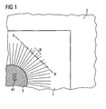
- Fig. 1 shows a section of a security document 2 according to the invention with a security element according to the invention 1.
- the security element 1 is also shown only as a section. It shows a sun on golden background, whereby the sun 3 is a transparent disk with fine transparent rays.
- the symbol 41 for the currency "EURO" can be recognized in the interior of the transparent solar disc, silver-colored.
- the gold-colored and silver-colored areas are each designed as a diffraction structure.
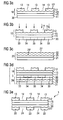
- Fig. 2a shows a first security element partial element 10, consisting of a first carrier substrate 11, a permeable to UV radiation film of PET, an embossing lacquer layer 15 applied thereon with embossed diffraction structure 15 'with a gold-colored metallization.
- the metallization forms a first functional layer 12 with golden first functional areas 13 and first recesses 14 therein.
- the diffraction structure 15 'of the embossing lacquer layer 15 can also be seen in the first functional regions 13 as a diffraction structure 13'.
- an adhesive layer 30 is applied.
- Fig. 2b shows the same representation as Fig. 2a , Wherein the arrows indicate that the security element subelement 10 is irradiated with UV radiation.
- the adhesive layer 30 separated by dashed lines, shielded by the first functional areas 13 and therefore not significantly changed in their adhesive force adhesive areas 33 and irradiated and thus deactivated adhesive areas 34 are indicated.
- the line 40 under the first carrier substrate 11 indicates an external radiation mask, the meaning of which will be explained later.
- Fig. 2c 2 shows a section through the second security element subelement 20 to be combined with the first security element subelement 10.
- the second security element subelement 20 consists of the second carrier substrate 21, the second functional layer 22 and an embossing lacquer layer 25 therebetween.
- the embossing lacquer layer 25 is a diffraction structure 25 'embossed, which is reproduced in the second functional layer 22 as a diffraction structure 22 '.
- the second functional layer 22 is a silver-colored metallization.
- the embossing lacquer 25 was washed off with an aqueous surfactant solution before the application of the metallization 22, with the result that the metallization 22 badly adheres to the embossing lacquer.
- Embodiments with different metallizations are particularly preferred.
- Fig. 2d shows how the irradiated first security element subelement 10 Fig. 2b and the second security element subelement 20 Fig. 2c be assembled into a composite 5.
- the two sub-elements are slightly compressed, whereby the diffraction structure 22 'of the second functional layer in the non-hardened regions 33 of the adhesive layer 30 is transferred to the adhesive layer.
- the first security element sub-element and the second security element sub-element are glued together. No adhesion takes place in the irradiated, and thus deactivated, regions 34 of the adhesive layer.
- the adhesive is hard and inert, so that the diffraction structure 22 'in the regions 34 does not transfer to the adhesive layer, which is indicated by the smooth surface in the regions 34.
- the second carrier substrate 21 and the embossing lacquer layer 25 are peeled off, for example by a separating winding.
- the result is in Fig. 2e shown.
- the regions of the second functional layer 22 lying over the adhesive regions 34 were removed together with the second carrier substrate and the embossing lacquer layer, while the regions of the second functional layer 22 bonded to the adhesive regions 33 were pulled off the embossing lacquer layer.
- the glued areas now form second functional areas 23 with second recesses 24 in between.
- the first recesses 14 and the second recesses 24 are exactly congruent and together form an opening 3 passing through both functional layers.
- the first functional regions 13 and the second functional regions 23 are also exactly congruent.
- a hot stamping foil can be used as a second security element sub-element.
- the second carrier substrate 21 would be peeled off during the separation winding, while the embossing lacquer layer 25 remains on the formed security element 1.
- It can also serve as a protective layer.
- a protective layer (not shown in the figure) over the second functional areas or the second functional layer is expedient.
- security element 1 applies a further adhesive layer and are irradiated through the functional layers.
- security element subelement as in FIG Fig. 2c shown).
- Fig. 2b is indicated by the reference numeral 40, an external exposure mask.
- the use of external masks is required when one of the functional layers is to contain functional areas at locations where the other functional layer has recesses. If the recesses are correspondingly large, there are no problems with regard to the achievable precision.
- FIG. 2b shown cross-section correspond to the two recesses 14 in the first functional layer 12 each rays of in Fig. 1 illustrated sun motif. The rays are very fine and therefore rather unsuitable for use with an additional external exposure mask. If one imagines that one of the recesses corresponds to the solar disk, then there would be a relatively large recess in area, into which a further representation can be integrated, for example, the one in FIG Fig.
- FIGS. 3a to 3e show the same security elements sub-elements 10 and 20 as the FIGS. 2a to 2e , Like reference numerals designate like elements. Unlike the FIGS. 2a to 2e Here, however, the adhesive layer 30 is mounted on the first carrier substrate, so that during the irradiation with the first functional layer 12 as a radiation mask ( Fig. 3b ) the irradiation mask is not directly adjacent to the adhesive layer to be irradiated. With the in Fig. 2 As a rule, therefore, a more precise imaging and thus also a more precise reproduction of very fine structures can take place.
- both functional layers 12 and 22 are arranged on the same side of the carrier substrate 11, whereas in the embodiment shown in FIG Fig. 3 shown variant on different sides of the carrier substrate.
- the adhesive layer 30 is applied to the second security element sub-element 20.
- the illustrations correspond to the FIGS. 4a to 4e and 5a to 5e the representations of the FIGS. 2a to 2e or 3a to 3e.
- Like reference numerals designate like elements.
- the adhesive layer 30 is applied to the second functional layer 22 of the second security element sub-element.
- the two security element partial elements must be joined together before the irradiation to form the composite 5. This is possible with different orientation of the first security element subelement, as in Fig. 4c and Fig. 5c shown.
- the first functional layer 12 is glued, and in the variant according to FIG Fig. 5c the first carrier substrate 11 is glued.
- FIGS. 2 to 5 describe the present invention by the use of a radiation deactivatable (curing) adhesive.
- a radiation-activatable adhesive can also be used.
- the regions 34 of the adhesive layer 30 would stick to the second functional layer 22, but the regions 33 would not.
- FIGS. 6a to 6e show the variant of the present invention, in which a thermoplastic resist is used as an adhesive.
- Like reference numerals again designate like elements as in the previous figures.
- Fig. 6a shows a first security element partial element 10 with first carrier substrate 11, embossing lacquer layer 15 with embossed diffraction structure 15 ', a metallization applied thereon as a first functional layer 12 and a resist coating 35 in the form of the desired motif.
- Fig. 6a So shows the state of the first security element partial element 10, in which the photoresist 35 has already been irradiated and developed.
- the photoresist 35 as in Fig. 6f shown irradiated through a mask, wherein the mask is patterned so that only the areas of the photoresist 35, in which recesses 14 are to be formed, are irradiated. In the embodiment shown, therefore, a positive photoresist is used.
- the use of a negative photoresist would require irradiation in the areas where the resist areas are to be formed.
- the photoresist After irradiation, the photoresist is developed with a suitable developer, whereby the security element sub-element 10, which in Fig. 6a is shown is obtained.
- Fig. 6b shows a second security element sub-element 20 that with the in Fig. 2c shown security element subelement is identical.
- the two in Fig. 6b and Fig. 6c shown elements are assembled into a composite 5, as in Fig. 6b shown.
- the layer sequence is the same as in FIG Fig. 2d shown composite 5. Due to increased pressure and elevated temperature of the adhesive, in particular thermoplastic resist is activated and glued now in the areas in which it is in contact with the second functional layer 22, with this functional layer. At the same time, the diffraction structure is transferred into the adhesive.
- FIG Fig. 6e shown security element 1 After stripping off the second carrier substrate 21 and the embossing lacquer layer 25, for example by means of a separation winding, the result obtained in FIG Fig. 6e shown security element 1, with the in Fig. 2e shown security element 1 seems to be identical.
- the security element shown in the recesses is still adhesive, which can optionally be used for additional effects (for example, can be colored), while in the in Fig. 6e shown security element in the recesses no adhesive is present.
- security element partial elements with adhesive, in particular thermoplastic, resist adhesive such as that described in US Pat Fig. 6b shown, with security elements that already have several functional layers, such as in Fig. 2e shown security element 1, are combined.
- the method according to the invention allows a register-accurate and edge-sharp formation of very fine structures with a width or a diameter of about 50 ⁇ m or less.
- a second security element subelement in which the motif of the functional layer is a metallized hologram or another metallized diffraction structure, a second security element subelement can alternatively be used, which has a carrier substrate with a layer formed thereon, which is used to form a metallized hologram or another metallized diffraction structure is suitable, has.
- a second security element subelement instead of the in Fig. 2c shown second security element subelement a in Fig. 7a shown metal donor sheet 20 are used without embossment, which has a support substrate 21 with a metallization 220 formed thereon.
- the metallization 220 of the metal donor film 20 is analogous to that in Fig. 2d shown method according to the invention with the adhesive layer 30 glued.
- the metallization 220 becomes, as in FIG Fig. 7b shown formed to areas 23.
- areas 23 are suitable areas for forming diffraction structures.
- embossing is performed under pressure and temperature to form the regions 23 into metallized diffraction structures.
- the embossing tool can be, for example, an embossing cylinder, a normal embossed foil or a metallised embossed foil.
- the security elements according to the invention can be in the form of transfer materials, i. H. Films or tapes are provided with a variety of finished and prepared for the transfer of security elements.
- the layer structure of the later security element is prepared on a carrier material in the reverse order in which the layer structure is later to be stored on a valuable object, wherein the layer structure of the security element in continuous form or already in the final outline form used as security element on the Carrier material can be prepared.
- the transfer of the security element to the object to be secured is effected by means of an adhesive layer, which is typically provided on the transfer material, but can also be provided on the object of value.
- a hot melt adhesive is used for this purpose.
- an adhesive layer can be provided for transfer either only in the areas of the security element to be transferred, or the adhesive is activated only in the areas to be transferred.
- the carrier material of the transfer elements is usually deducted from the layer structure of the security elements during or after their transfer to the valuable article.
- a separating layer release layer
- the carrier material can also remain on the transmitted security element.
- the security elements according to the invention can be used to authenticate goods of any kind.
- they are used to authenticate value documents, for example banknotes, checks or identity cards. They can be arranged on a surface of the value document or completely or partially in the value document will be embedded. With particular advantage they are used in value documents hole hole hole.
- the advantages of the security elements according to the invention with transparent carrier substrates and from both sides of the value document to be considered, carefully adapted motifs can be particularly beautiful. Even negatives with the finest structures can be clearly recognized in transmitted light. You are in the achievable according to the invention precision of a counterfeiter practically imitated.
- a detachment of the security elements to transfer them to another valuable item, is practically not possible, because the security elements according to the invention always contain at least two adhesive layers, or they contain an adhesive layer and are connected with a further adhesive layer with the valuable object to be secured. If, for the bonding of the security element to the object of value, an adhesive which is similar in terms of its chemical and physical properties to the adhesive in the layer structure of the security element, the layer structure of the security element is always destroyed during detachment attempts.
Description
Die Erfindung betrifft ein Verfahren zur Herstellung eines Sicherheitselements mit zwei oder mehr zueinander gepasserten Motivschichten, insbesondere Motivschichten mit im Durchlicht und bevorzugt auch im Auflicht visuell erkennbaren Zeichen, ein mittels des Verfahrens erhältliches Sicherheitselement, das als Transferelement ausgebildete Sicherheitselement, die Verwendung des Sicherheitselements bzw. Transferelements zur Produktsicherung, einen mit dem Sicherheitselement ausgestatteten Wertgegenstand sowie ein Verfahren zur Herstellung eines derartigen Wertgegenstands.The invention relates to a method for producing a security element having two or more motif layers matched to one another, in particular motif layers having characters visually recognizable in transmitted light and preferably also in reflected light, a security element obtainable by the method, the security element designed as a transfer element, the use of the security element or Product safety transfer element, a valuable article equipped with the security element, and a method of manufacturing such a valuable article.
Wertgegenstände, insbesondere Wertdokumente, wie Banknoten, Aktien, Ausweise, Kreditkarten, Urkunden, Schecks, und andere fälschungsgefährdete Papiere, wie Ausweisdokumente unterschiedlichster Art, aber auch Markenartikel und Verpackungen von Markenartikeln werden zur Absicherung gerne mit Sicherheitselementen ausgestattet, die eine Überprüfung ihrer Echtheit ermöglichen und gleichzeitig als Schutz vor unerlaubter Reproduktion dienen. Die Sicherheitselemente können beispielsweise die Form von Sicherheitsfäden oder Aufklebern oder irgendeine andere in einen Wertgegenstand oder ein Sicherheitspapier einbringbare oder aufbringbare Form haben, wobei ein "Wertgegenstand" im Sinne der vorliegenden Erfindung jeder gegen Fälschung sicherungswerte Gegenstand ist, insbesondere ein Wertdokument, während ein "Sicherheitspapier" die noch nicht umlauffähige Vorstufe zu einem Wertdokument darstellt.Valuables, in particular documents of value, such as banknotes, shares, identity cards, credit cards, certificates, checks, and other forgery-prone papers, such as identity documents of various kinds, but also branded goods and packaging of branded goods are gladly provided with security elements for security, which allow verification of their authenticity and at the same time serve as protection against unauthorized reproduction. The security elements may, for example, take the form of security threads or stickers or any other form insertable or attachable to a valuable article or security paper, a "valuable article" within the meaning of the present invention being any objectionable to counterfeiting, in particular a value document, while a "security paper "represents the precursor to a value document, which is not yet ready for use.
Sicherheitselemente sind typischerweise mehrschichtige Elemente mit mehreren Funktionsschichten. Funktionsschichten sind ganz allgemein Schichten, die irgendwelche Eigenschaften aufweisen, die visuell oder maschinell nachgewiesen werden können. Funktionsschichten enthalten daher beispielsweise Farbstoffe, Lumineszenzstoffe, thermochrome Stoffe, Flüssigkristalle, Interferenzpigmente, elektrisch leitfähige Stoffe, magnetische Stoffe, lichtbeugende oder lichtbrechende Strukturen oder Kombinationen davon. Die Funktionsschichten sind meist als geometrische oder figürliche Muster oder Motive ausgebildet, d. h. es gibt innerhalb einer Schicht Funktionsbereiche mit der nachweisbaren Eigenschaft (beispielsweise Lumineszenz) und Aussparungen dazwischen. Werden mehrere Funktionsschichten übereinander angeordnet, ist es in der Regel wünschenswert, dass die Funktionsbereiche und die Aussparungen in den einzelnen Funktionsschichten exakt registerhaltig, d. h. mit hoher Passergenauigkeit, und mit konturenscharfen Kanten zwischen den Funktionsbereichen und den Aussparungen übereinander ausgebildet sind. Auf diese Weise kann eine Funktionsschicht unter einer anderen versteckt werden, beispielsweise magnetische Stoffe unter einer Farbschicht, oder es können Sicherheitselemente mit mehreren Funktionsschichten und "Negativschrift" hergestellt werden. Sicherheitselemente mit Negativschrift weisen ein transparentes Substrat mit mindestens einer nicht transparenten Beschichtung, die Aussparungen (die Negativschrift) aufweist, auf. Diese Aussparungen können beliebige Formen haben, beispielsweise Buchstaben, Zahlen oder Muster irgendwelcher Art, insbesondere Linienmuster. Der in dieser Anmeldung verwendete Begriff "Negativschrift" umfasst demnach Aussparungen beliebiger Form, also jede Nicht-Vollflächigkeit in einer nicht transparenten Beschichtung. Je transparenter, d. h. je lichtdurchlässiger, das Trägersubstrat ist, desto ausgeprägter ist der Kontrast zwischen beschichteten und nicht beschichteten Bereichen. Bei sehr transparenten Substraten ist die Negativschrift im Auflicht deutlich erkennbar, bei weniger transparenten Substraten nur im Durchlicht. Weist ein derartiges Sicherheitselement mit Negativschrift zwei unterschiedliche Funktionsschichten auf, beispielsweise ein Motiv in Form einer goldfarbenen metallischen Beschichtung und darauf dasselbe Motiv als rote Druckfarbe, so erscheint dieses Motiv dem Betrachter von der einen Seite her gesehen goldfarben, von der anderen Seite her gesehen rot.Security elements are typically multilayer elements with multiple functional layers. Functional layers are generally layers that have any properties that can be detected visually or by machine. Functional layers therefore contain, for example, dyes, luminescent substances, thermochromic substances, liquid crystals, Interference pigments, electrically conductive substances, magnetic substances, light-diffractive or refractive structures or combinations thereof. The functional layers are usually designed as geometric or figurative patterns or motifs, ie there are functional areas within a layer with the detectable property (for example luminescence) and recesses in between. If a plurality of functional layers are arranged one above the other, it is generally desirable for the functional regions and the recesses in the individual functional layers to be formed exactly in register, ie with high register accuracy, and with contour-sharp edges between the functional regions and the recesses. In this way, one functional layer can be hidden under another, for example magnetic substances under a colored layer, or security elements with multiple functional layers and "negative writing" can be produced. Negative-type security elements comprise a transparent substrate having at least one non-transparent coating having recesses (the negative writing). These recesses may have any shapes, such as letters, numbers or patterns of any kind, especially line patterns. The term "negative writing" used in this application accordingly comprises recesses of any shape, ie any non-solidity in a non-transparent coating. The more transparent, ie the more translucent, the carrier substrate is, the more pronounced is the contrast between coated and uncoated regions. In the case of very transparent substrates, the negative writing is clearly recognizable in incident light, with less transparent substrates only in transmitted light. If such a security element with negative writing has two different functional layers, for example a motif in the form of a gold-colored metallic coating and the same motif as the red printing ink, then this motif appears golden to the viewer from one side, red from the other side.
Derartige mehrschichtige Motive sind aufgrund der erforderlichen hohen Passergenauigkeit schwer nachahmbar. Insbesondere Motive mit Negativschriften bieten einen guten Fälschungsschutz, da im Durchlicht Ungenauigkeiten bei der Herstellung besonders leicht erkennbar sind, und "primitive" Fälschungsversuche, wie etwa das Kopieren mit Farbkopierem, auch für das ungeübte Auge sofort erkennbar sind.Such multilayer motifs are difficult to imitate due to the required high registration accuracy. In particular, subjects with negative fonts provide good protection against counterfeiting, since in the transmitted light inaccuracies in the production are particularly easily recognizable, and "primitive" counterfeiting attempts, such as copying with Farbkopierem, even for the untrained eye are immediately recognizable.
Die Fälschungssicherheit ist umso höher, je feiner die Strukturen in den Funktionsschichten mit den zueinander gepasserten Motiven sind. Feinste Strukturen konturenscharf und im perfekten Register zueinander auszubilden, stellt allerdings auch für autorisierte Hersteller eine Herausforderung dar. Es sind eine Reihe von Verfahren bekannt, die es ermöglichen sollen, Aussparungen in mehreren übereinander liegenden Funktionsschichten passergenau, d. h. deckungsgleich in allen Schichten, auszubilden.The tamper-proof is the higher the finer the structures in the functional layers are with the matched-to-each other motifs. Finely contoured structures and in perfect register form each other, however, also presents a challenge for authorized manufacturers. A number of methods are known which are intended to enable recesses in a plurality of superimposed functional layers to be registered precisely. H. congruent in all layers, train.
Aus
Dokument
- "Verfahren zur Herstellung eines Sicherheitselements für ein Sicherheitspapier oder ein Wertgegenstand folgende Schritte aufweisend:
- a) Bereitstellen eines ersten Sicherheitselement-Teilelements, aufweisend
- ein erstes Trägersubstrat,
- eine erste Funktionsschicht mit ersten Funktionsbereichen und ersten Aussparungen,
- eine Schicht aus Klebstoff auf der ersten Funktionsschicht, die mit den ersten Funktionsbereichen deckungsgleich ist,
- b) Bereitstellen eines zweiten Sicherheitselement-Teilelements, aufweisend:
- ein zweites Trägersubstrats,
- eine zweite Funktionsschicht auf dem zweiten Trägersubstrat, wobei die zweite Funktionsschicht von dem zweiten Trägersubstrat abziehbar ist,
- d) Zusammensetzen des ersten und des zweiten Sicherheitselement-Teilelements zu einem Verbund dergestalt, dass
- d1) die Klebstoffschicht und die zweite Funktionsschicht des zweiten Sicherheitselement-Teilelements zueinander weisen,
- f) Verkleben des ersten und des zweiten Sicherheitselement-Teilelements, wobei die Verklebung durch die Bereiche mit Klebstoff bewirkt wird,
- g) Abtrennen des zweiten Trägersubstrats von dem Verklebten Verbund, wobei die zweite Funktionsschicht unter Ausbildung von zweiten Funktionsbereichn
- g3) in den Bereichen mit Klebstoff haften bleibt, in den Bereichen ohne Klebstoff aber nicht haftet und zusammen mit dem zweiten Trägersubstrat abgetrennt wird"
- a) Bereitstellen eines ersten Sicherheitselement-Teilelements, aufweisend
- A method of manufacturing a security element for a security paper or a valuable article comprising the steps of:
- a) providing a first security element subelement comprising
- a first carrier substrate,
- a first functional layer having first functional areas and first recesses,
- a layer of adhesive on the first functional layer that is congruent with the first functional areas,
- b) providing a second security element subelement, comprising:
- a second carrier substrate,
- a second functional layer on the second carrier substrate, wherein the second functional layer is removable from the second carrier substrate,
- d) assembling the first and second security element subelements into a composite such that
- d1) the adhesive layer and the second functional layer of the second security element partial element point towards each other,
- f) bonding the first and second security element sub-elements, wherein the bonding is effected by the areas with adhesive,
- g) separating the second carrier substrate from the bonded composite, the second functional layer forming second functional regions
- g3) adheres in the areas with adhesive, but does not adhere in the areas without adhesive and is separated off together with the second carrier substrate "
- a) providing a first security element subelement comprising
Die genannten Verfahren funktionieren zufriedenstellend, solange keine sehr feinen Strukturen auszubilden sind. Sehr feine Strukturen können mit dem genannten Verfahren aber häufig nicht konturenscharf und passergenau ausgebildet werden.The methods mentioned work satisfactorily, as long as no very fine structures are to be formed. However, very fine structures can often not be contour-sharp and accurate in registration with the mentioned method.
Aufgabe der vorliegenden Erfindung ist es daher, ein Verfahren zur Herstellung von Sicherheitselementen bereitzustellen, das es erlaubt, in mindestens zwei übereinanderliegenden Schichten deckungsgleiche Motive auszubilden.The object of the present invention is therefore to provide a method for the production of security elements, which makes it possible to form congruent motifs in at least two superimposed layers.
Aufgabe der vorliegenden Erfindung ist es insbesondere, ein derartiges Verfahren bereitzustellen, mit dem deckungsgleiche Motive konturenscharf und mit hoher Passergenauigkeit ausgebildet werden können.The object of the present invention is, in particular, to provide such a method, with which congruent motifs can be formed with sharp contours and with high register accuracy.
Aufgabe der vorliegenden Erfindung ist es darüber hinaus, ein derartiges Verfahren bereitzustellen, wobei die auszubildenden Motive sehr feine Strukturen aufweisen.It is also an object of the present invention to provide such a method, wherein the motifs to be formed have very fine structures.
Aufgabe der vorliegenden Erfindung ist es auch, ein Sicherheitselement mit mindestens zwei Motivschichten mit einander entsprechenden Motiven, die eine hohe Passergenauigkeit aufweisen, bereitzustellen.It is also an object of the present invention to provide a security element having at least two motif layers with mutually corresponding motifs which have a high register accuracy.
Aufgabe der vorliegenden Erfindung ist es ferner, ein derartiges Sicherheitselement bereitzustellen, bei dem die Motivschichten sehr feine Strukturen aufweisen und konturenscharf ausgebildet sind.It is also an object of the present invention to provide such a security element in which the motif layers have very fine structures and are of sharp contours.
Aufgabe der vorliegenden Erfindung ist es darüber hinaus, derartige Sicherheitselemente in Form von Transferelementen bereitzustellen sowie Sicherheitspapiere und Wertgegenstände mit den erfindungsgemäßen Sicherheitselementen bzw. Transferelementen und Verfahren zur Herstellung der Sicherheitspapiere und der Wertgegenstände bereitzustellen.It is also an object of the present invention to provide such security elements in the form of transfer elements and to provide security papers and valuables with the security elements or transfer elements according to the invention and methods for producing the security papers and the valuables.
Die Aufgaben werden gelöst durch das Verfahren zur Herstellung eines Sicherheitselements mit den in Anspruch 1 angegebenen Merkmalen, durch das Sicherheitselement mit den in Anspruch 8 angegebenen Merkmalen, durch das Transfermaterial mit den in Anspruch 15 angegebenen Merkmalen, durch das Sicherheitspapier bzw. den Wertgegenstand gemäß Anspruch 16 und durch das Verfahren gemäß Anspruch 17.The objects are achieved by the method for producing a security element having the features specified in
Spezielle Ausführungsformen der vorliegenden Erfindung sind in den jeweiligen abhängigen Ansprüchen angegeben.Specific embodiments of the present invention are set forth in the respective dependent claims.
Der Grundgedanke der vorliegenden Erfindung besteht darin, das Motiv einer Funktionsschicht mithilfe einer Klebstoffschicht in eine andere Funktionsschicht zu übertragen. Dabei wird in der Klebstoffschicht ein exaktes Abbild des Motivs der ersten Funktionsschicht reproduziert, und dieses Abbild des Motivs in der Klebstoffschicht wiederum dazu verwendet, ein exaktes Abbild dieses Motivs oder seines fotografischen Negativs in einer weiteren Funktionsschicht zu reproduzieren. Die Übertragung des Motivs von der einen Funktionsschicht in die andere gelingt dadurch, dass der Klebstoff zwischen den Funktionsschichten mithilfe des Motivs der ersten Funktionsschicht so strukturiert wird, dass er nur an bestimmten Bereichen der zweiten Funktionsschicht haftet, mit den übrigen Bereichen der zweiten Funktionsschicht jedoch keine Klebeverbindung eingeht. Die nicht verklebten Bereiche der zweiten Funktionsschicht werden dann entfernt, während die verklebten Bereiche nicht entfernt werden können, wodurch in der zweiten Funktionsschicht eine exakte Reproduktion oder ein fotografisches Negativ des Motivs der ersten Funktionsschicht entsteht.The basic idea of the present invention is to transfer the motif of a functional layer into another functional layer with the aid of an adhesive layer. In this case, an exact image of the motif of the first functional layer is reproduced in the adhesive layer, and this image of the motif in the adhesive layer is in turn used to produce a precise image Reproduce the image of this motif or its photographic negative in another functional layer. The transfer of the motif from one functional layer to the other succeeds in that the adhesive between the functional layers is structured using the motif of the first functional layer so that it adheres only to certain areas of the second functional layer, but none with the other regions of the second functional layer Adhesive connection is received. The non-bonded regions of the second functional layer are then removed, while the bonded regions can not be removed, whereby an exact reproduction or a photographic negative of the motif of the first functional layer arises in the second functional layer.
Das erfindungsgemäße Sicherheitselement wird aus mindestens zwei Teilelementen hergestellt. Ein erstes Teilelement besteht mindestens aus einem Trägersubstrat und einer Funktionsschicht mit Aussparungen darin. Weitere Schichten können vorhanden sein. Die Funktionsschicht kann auch aus mehreren Einzelschichten aufgebaut sein.The security element according to the invention is produced from at least two partial elements. A first sub-element consists at least of a carrier substrate and a functional layer with recesses therein. Additional layers may be present. The functional layer can also be composed of several individual layers.
Das Trägersubstrat des ersten Sicherheitselement-Teilelements ist bevorzugt eine Folie, beispielsweise aus Polypropylen, Polyethylen, Polystyrol, Polyester, insbesondere Polycarbonat oder Polyethylenterephthalat. Transparente oder transluzente Folien sind besonders bevorzugt. Bei einer Verwendung derartiger Folien können die passergenau ausgebildeten Aussparungen in den einzelnen Funktionsschichten deutlich als Negativschrift erkannt werden.The carrier substrate of the first security element partial element is preferably a film, for example made of polypropylene, polyethylene, polystyrene, polyester, in particular polycarbonate or polyethylene terephthalate. Transparent or translucent films are particularly preferred. When using such films, the register-formed recesses in the individual functional layers can be clearly recognized as negative writing.
Auf dem Trägersubstrat wird eine Funktionsschicht ausgebildet. Die Funktionsschicht kann grundsätzlich von beliebiger Art sein, wie sie bei Sicherheitselementen verwendet wird. Als Beispiele seien genannt Metallschichten aus beispielsweise Aluminium, Eisen, Kupfer, Gold, Nickel, etc., Metalllegierungen, oder Schichten aus Metalleffektfarben, Schichten mit Farbpigmenten oder Fluoreszenzpigmenten, Flüssigkristallschichten, Beschichtungen mit Farbkippeffekt, Schichtkombinationen, wie beispielsweise eine mit einer bestimmten Farbe unterlegte Schicht mit Farbkippeffekt, Schichten mit maschinell nachweisbaren Merkmalen, beispielsweise mit Magnetpigmenten, die gegebenenfalls unter einer Deckschicht versteckt werden können. Bei der erwähnten Schicht mit Farbpigmenten kann es sich z. B. um eine schwarze Druckfarbe auf der Basis von "Microlith Schwarz" (Ciba) handeln, die bei dem erfindungsgemäß hergestellten Sicherheitselement einen dunklen Hintergrund für z. B. Flüssigkristallschichten bildet, was die Erzeugung eindrucksvoller Farbkippeffekte ermöglicht.On the carrier substrate, a functional layer is formed. The functional layer can basically be of any type as used in security elements. As examples may be mentioned metal layers for example, aluminum, iron, copper, gold, nickel, etc., metal alloys, or layers of metallic effect paints, layers with color pigments or fluorescent pigments, liquid crystal layers, coatings with color shift effect, layer combinations, such as a color-shaded layer with a color shift effect, layers with mechanically detectable features, for example, with magnetic pigments, which may optionally be hidden under a cover layer. In the mentioned layer with color pigments, it may, for. B. to a black ink on the basis of "Microlith Black" (Ciba), which in the security element according to the invention prepared a dark background for z. B. forms liquid crystal layers, which allows the generation of impressive color shift effects.
Die Aufbringung der Funktionsschichten erfolgt nach bekannten Verfahren, die für die jeweilige Funktionsschicht geeignet sind, beispielsweise durch physikalische Dampfabscheidung (PVD) bei Metallen oder durch Aufdrucken bei Farbpigmenten oder Fluoreszenzpigmenten.The application of the functional layers is carried out by known methods that are suitable for the respective functional layer, for example by physical vapor deposition (PVD) in metals or by printing on color pigments or fluorescent pigments.
Werden Funktionsschichten aufgedruckt, können sie gewünschtenfalls bereits in Form des Funktionsschicht-Motivs aufgedruckt werden, d. h. in Form von Funktionsbereichen und Aussparungen zwischen diesen Bereichen. In allen anderen Fällen erfolgt eine vollflächige Auftragung der Funktionsschicht, wobei selbstverständlich auch aufgedruckte Funktionsschichten vollflächig aufgedruckt werden können.If functional layers are printed on, they can, if desired, already be printed in the form of the functional layer motif, i. H. in the form of functional areas and recesses between these areas. In all other cases, there is a full-surface application of the functional layer, whereby of course also printed functional layers can be printed over the entire surface.
Die Funktionsschicht kann direkt auf dem Trägersubstrat ausgebildet werden, oder es können eine oder mehrere Zwischenschichten vorgesehen werden. Für manche Funktionsschichten sind Zwischenschichten zwingend erforderlich, beispielsweise wenn es sich bei dem Motiv der Funktionsschicht um ein metallisiertes Hologramm, Kinegramm, Pixelgramm oder eine sonstige metallisierte Beugungsstruktur handelt. In einem solchen Fall wird zuerst eine Prägelackschicht aufgetragen und in die Prägelackschicht, vor oder nach der Metallisierung, die gewünschte diffraktive Struktur eingeprägt. Auch bei Flüssigkristallschichten ist in der Regel eine Zwischenschicht erforderlich, die für eine passende Orientierung der Flüssigkristalle sorgt. Geeignete Orientierungsschichten können beispielsweise in Prägelackschichten eingeprägte diffraktive Strukturen sein. Alternativ kann gegebenenfalls auch die Trägerfolie geeignet behandelt werden.The functional layer can be formed directly on the carrier substrate, or one or more intermediate layers can be provided. For some functional layers, intermediate layers are absolutely necessary, for example if the motif of the functional layer is is a metallized hologram, kinegram, pixelgram or other metallized diffraction structure. In such a case, first an embossing lacquer layer is applied and embossed into the embossing lacquer layer, before or after the metallization, the desired diffractive structure. In the case of liquid crystal layers as well, an intermediate layer is generally required which ensures a suitable orientation of the liquid crystals. Suitable orientation layers can be, for example, embossed lacquer layers embossed diffractive structures. Alternatively, if appropriate, the carrier film can also be suitably treated.
Gemäß einer bevorzugten Ausführungsform der vorliegenden Erfindung ist eine der Motivschichten eine metallisierte Beugungsstruktur, wie ein metallisiertes Hologramm, besonders bevorzugt ist auch eine weitere Motivschicht eine metallisierte Beugungsstruktur, wie ein metallisiertes Hologramm. Wenn im Folgenden von Hologrammen gesprochen wird, versteht es sich, dass dasselbe auch für andere Beugungsstrukturen und Brechungsstrukturen gilt sowie für sogenannte "Mattstrukturen"" (Gitterbilder mit achromatischen Gitterbereichen), wie sie z. B. in der
Wie oben erwähnt, ist im Falle von Hologrammen eine Prägelackschicht vorzusehen, die die gewünschte Strukturinformation eingeprägt enthält. Die Strukturinformation wird beim Verkleben mit dem zweiten Sicherheitselement-Teilelement mit übertragen. Materialien für Prägelackschichten sind einem Fachmann bekannt. Geeignete Prägelacke sind beispielsweise offenbart in
In einem weiteren Schritt wird die Funktionsschicht zur Herstellung eines Motivs strukturiert, d. h. aus der Funktionsschicht werden bestimmte Bereiche entfernt. Die verbleibenden Funktionsbereiche und die Aussparungen bilden zusammen das Motiv, das eine beliebige geometrische oder figürliche Darstellung sein kann. Das Motiv kann auch eine Codierung bilden, oder es kann die Form der Aussparungen so gestaltet sein, dass die Aussparungen von einem Betrachter als das "Motiv" empfunden werden.In a further step, the functional layer is structured to produce a motif, i. H. certain areas are removed from the functional layer. The remaining functional areas and the recesses together form the motif, which can be any geometric or figurative representation. The motif can also form an encoding, or the shape of the recesses can be designed so that the recesses are perceived by a viewer as the "motif".
Verfahren zur Herstellung der Aussparungen sind bekannt. Geeignet sind beispielsweise Laserablation, Ätzverfahren und Waschverfahren. Ätzverfahren sind insbesondere für metallische Funktionsschichten geeignet. Auf die metallische Schicht wird ein Fotoresist aufgetragen und durch eine Maske in Form des gewünschten Motivs belichtet. Bei positiv arbeitenden Fotoresists müssen die Bereiche der späteren Aussparungen belichtet werden, bei negativ arbeitenden Fotoresists die späteren Funktionsbereiche. Nach der Belichtung wird der Fotoresist in den löslichen Bereichen mittels Entwickler entfernt und die Metallschicht in den freigelegten Bereichen durch Ätzmittel, wie Laugen oder Säuren, unter Bildung der gewünschten Aussparungen weggeätzt.Methods for producing the recesses are known. For example, laser ablation, etching and washing methods are suitable. Etching processes are particularly suitable for metallic functional layers. On the metallic layer, a photoresist is applied and exposed through a mask in the form of the desired motif. In the case of positive-working photoresists, the areas of the later recesses must be exposed; in the case of negative-working photoresists, the later functional areas must be exposed. After exposure, the photoresist in the soluble areas is removed by developer and the metal layer in the exposed areas is etched away by etchants such as caustics or acids to form the desired recesses.
Waschverfahren sind universell einsetzbar. Geeignete Waschverfahren sind beispielsweise offenbart in
Als nächstes wird das zweite Sicherheitselement-Teilelement hergestellt.Next, the second security element subelement is manufactured.
Das zweite Sicherheitselement-Teilelement weist, wie das erste Sicherheitselement-Teilelement, mindestens zwei Schichten auf, nämlich ein Trägersubstrat und eine darauf ausgebildete Funktionsschicht. Zusätzlich können weitere Schichten vorhanden sein bzw. müssen vorhanden sein, wie vorstehend für das erste Sicherheitselement-Teilelement ausgeführt wurde.The second security element subelement has, like the first security element subelement, at least two layers, namely a carrier substrate and a functional layer formed thereon. In addition, other layers may be present or need to be present as stated above for the first security element subelement.
Generell gilt für die Materialien, den Aufbau und die Herstellung der Schichten des zweiten Sicherheitselement-Teilelements dasselbe wie für das erste Sicherheitselement-Teilelement, wobei jedoch zu beachten ist, dass in der Funktionsschicht oder der Funktionsschichtfolge keine Aussparungen ausgebildet werden. Die Aussparungen werden erst durch Zusammenwirken mit dem ersten Sicherheitselement-Teilelement erzeugt. Außerdem wird das Trägersubstrat des zweiten Sicherheitselement-Teilelements später zusammen mit Teilen der Funktionsschicht des zweiten Sicherheitselement-Teilelements abgetrennt, z. B. durch Trennwicklung, abgezogen (z. B. den Teilen der Funktionsschicht, die in dem zusammengesetzten Sicherheitselement über Aussparungen in der Funktionsschicht des ersten Sicherheitselement-Teilelements angeordnet sind), während sich das Trägersubstrat von anderen Teilen der Funktionsschicht des zweiten Sicherheitselement-Teilelements (z. B. den Teilen, die in dem zusammengesetzten Sicherheitselement über Funktionsbereichen des ersten Sicherheitselement-Teilelements angeordnet sind), ablösen lassen muss. Daher ist es erforderlich, dass die Funktionsschicht nur eine geringe Haftung an dem Trägersubstrat besitzt.In general, the same applies to the materials, the structure and the production of the layers of the second security element subelement as to the first security element subelement, wherein, however, it should be noted that no recesses are formed in the functional layer or the functional layer sequence. The recesses are only produced by cooperation with the first security element subelement. In addition, the carrier substrate of the second security element subelement is later separated together with parts of the functional layer of the second security element subelement, for. By parting winding (eg the parts of the functional layer which are arranged in the composite security element via recesses in the functional layer of the first security element subelement), while the carrier substrate is separated from other parts of the functional layer of the second security element subelement ( For example, the parts that are located in the composite security element over functional areas of the first security element sub-element must peel off. Therefore, it is necessary that the functional layer has only a slight adhesion to the carrier substrate.
Die erforderliche geringe Haftkraft wird bei vielen Funktionsschichtmaterialien, insbesondere Metallisierungen, schon alleine dadurch erreicht, dass auf haftvermittelnde Maßnahmen zwischen Trägersubstrat und Funktionsschicht verzichtet wird. Das Treffen haftvermittelnder Maßnahmen zwischen den einzelnen Schichten eines Sicherheitselements ist ansonsten üblich, und die entsprechenden Vorkehrungen einem Fachmann bekannt.The required low adhesion force is already achieved in many functional layer materials, in particular metallizations, by omitting adhesion-promoting measures between the carrier substrate and the functional layer. The meeting of adhesion-promoting measures between The individual layers of a security element is otherwise customary, and the corresponding provisions known to a person skilled in the art.
Wenn die Haftkraft zwischen Trägersubstrat und Funktionsschicht zu hoch ist, kann sie durch Behandeln des Trägersubstrats mit geeigneten Additiven herabgesetzt werden. Beispielsweise kann das Trägersubstrat mit Wasser und/oder Lösungsmitteln mit oder ohne geeignete Additive abgewaschen werden. Als entsprechende Additive geeignet sind beispielsweise tensidisch wirkende Substanzen, Entschäumer oder Verdicker.If the adhesive force between the carrier substrate and the functional layer is too high, it can be reduced by treating the carrier substrate with suitable additives. For example, the carrier substrate can be washed off with water and / or solvents with or without suitable additives. Suitable additives are, for example, surface-active substances, defoamers or thickeners.
Analoges gilt für gegebenenfalls zwischen dem Trägersubstrat und der Funktionsschicht vorhandene Zwischenschichten, beispielsweise Prägelackschichten für ein Hologramm. Soll eine derartige Prägelackschicht oder sonstige Zwischenschicht zusammen mit dem Trägersubstrat abgezogen werden, muss entsprechend die Haftkraft zwischen der Zwischenschicht und der Funktionsschicht, also beispielsweise zwischen der Prägelackschicht und einer darauf aufgebrachten Metallisierung, gering sein. Im Falle einer zu hohen Haftkraft ist die Zwischenschicht mit den genannten Additiven zu behandeln.The same applies to any intermediate layers present between the carrier substrate and the functional layer, for example embossing lacquer layers for a hologram. If such an embossing lacquer layer or other intermediate layer is to be taken off together with the carrier substrate, the adhesive force between the intermediate layer and the functional layer, ie for example between the embossing lacquer layer and a metallization applied thereon, must be correspondingly low. If the adhesive force is too high, the intermediate layer should be treated with the additives mentioned.
Wird eine Behandlung des Trägersubstrats oder einer Zwischenschicht mit haftverringernden Additiven vorgenommen, können nach dem Abtrennen des Trägersubstrats bzw. der Zwischenschicht Reste der Additive auf der Funktionsschicht verbleiben. Diese können normalerweise einfach mit einer wässrigen Lösung, deren pH geeignet eingestellt ist und die gegebenenfalls auch Tenside enthalten kann, weggewaschen werden. Auch eine Wäsche mit Lösungsmitteln ist möglich. In hartnäckigen Fällen kann auch mit Hochdruckdüsen und/ oder mechanischer Unterstützung (Filze, Bürsten) gearbeitet werden, doch dies ist für gewöhnlich nicht erforderlich. Geringe Additivreste können auch mittels einer Koronabehandlung "weggebrannt" werden. Im Übrigen kann in vielen Fällen auch ganz auf eine Entfernung von Additivresten verzichtet werden. Geeignete formulierte Schutzlacke können auch auf "additivbelasteten" Funktionsschichten ausreichend haften.If a treatment of the carrier substrate or an intermediate layer with adhesion-reducing additives is carried out, residues of the additives can remain on the functional layer after the carrier substrate or the intermediate layer has been separated off. These can normally be washed away simply with an aqueous solution whose pH is suitably adjusted and which may optionally also contain surfactants. Even a laundry with solvents is possible. In persistent cases, high-pressure nozzles and / or mechanical support (felts, brushes) can be used, but this is usually not necessary. Low additive residues can also be "burned away" by means of a corona treatment. Incidentally, in many cases it is also possible to completely dispense with the removal of additive residues. Suitable formulated conformal coatings can also adhere adequately to "additive-loaded" functional layers.
Nun werden das erste Sicherheitselement-Teilelement, das eine Funktionsschicht mit Funktionsbereichen und Aussparungen aufweist, und das zweite Sicherheitselement-Teilelement, das eine Funktionsschicht ohne Aussparungen aufweist, mithilfe einer Klebstoffschicht miteinander verbunden. Eine geeignete Klebstoffschicht kann eventuell bereits auf dem ersten Sicherheitselement-Teilelement vorhanden sein, nämlich wenn die Aussparungen in der Funktionsschicht des ersten Sicherheitselement-Teilelements mithilfe eines klebefähigen Resistlacks erzeugt wurden. Dabei werden die Aussparungen durch Beschichten mit Fotoresist, Belichten mittels einer externen Maske, Entwickeln und Wegätzen der nicht mehr durch Fotoresist geschützten Bereiche der Funktionsschicht hergestellt. Auf den übrigen Bereichen der Funktionsschicht, den Funktionsbereichen, befindet sich nach wie vor Fotoresistmaterial, das zwangsläufig mit den Funktionsbereichen deckungsgleich ist. Dieses Fotoresistmaterial kann, sofern es unter Druck und erhöhter Temperatur gut mit dem Material der Funktionsschicht des zweiten Sicherheitselement-Teilelements verklebbar ist, als Klebstoffschicht verwendet werden. Wurde ein ungeeigneter Fotoresist benutzt oder sind die Fotoresistbereiche für eine exakte Verklebung nicht mehr ausreichend intakt, wird der Fotoresist entfernt und anschließend wie in allen anderen Fällen verfahren, in denen die Aussparungen in der Funktionsschicht des ersten Sicherheitselements-Teilelements ohne Verwendung eines Fotoresists erzeugt wurden. Bei dem eingesetzten Fotoresist kann es sich um einen positiven Fotoresist, wie AZ 1512 (AZ 1500 Serie) oder AZ P 4620 von Clariant oder S 1822 von Shipley handeln, der in einer Flächendichte von ca. 0,1 g/m2 bis ca. 40 g/m2 aufgebracht wird.Now, the first security element subelement, which has a functional layer with functional regions and recesses, and the second security element subelement, which has a functional layer without recesses, are connected to one another with the aid of an adhesive layer. A suitable adhesive layer may possibly already be present on the first security element subelement, namely if the recesses were produced in the functional layer of the first security element subelement with the aid of a stickable resist. The recesses are produced by coating with photoresist, exposing by means of an external mask, developing and etching away the areas of the functional layer which are no longer protected by photoresist. On the other areas of the functional layer, the functional areas, there is still photoresist material, which is necessarily congruent with the functional areas. This photoresist material can be used as the adhesive layer, provided that it can be bonded well to the material of the functional layer of the second security element partial element under pressure and elevated temperature. If an unsuitable photoresist is used, or if the photoresist areas are no longer sufficiently intact for accurate bonding, the photoresist is removed and then proceeded as in all other cases where the recesses in the functional layer of the first security element subelement were created without using a photoresist. The photoresist used may be a positive photoresist such as AZ 1512 (AZ 1500 series) or AZ P 4620 from Clariant or S 1822 from Shipley, which is applied in an areal density of about 0.1 g / m 2 to about 40 g / m 2 .
In diesen Fällen wird zur Verklebung des ersten Sicherheitselement-Teilelements und des zweiten Sicherheitselement-Teilelements ein strahlenhärtender, bevorzugt ein UV-härtender, oder ein strahlenaktivierbarer, Klebstoff verwendet. Bei der Auftragung des Klebstoffs und der Kombination der Teilelemente miteinander muss berücksichtigt werden, dass erfindungsgemäß die Klebekraft des Klebstoffs durch Bestrahlung unter Verwendung der Funktionsschicht des ersten Sicherheitselement-Teilelements als Maske so verändert wird, dass entweder in den Aussparungsbereichen im Wesentlichen keine Klebekraft mehr vorhanden ist, während in den Funktionsbereichen die Klebekraft im Wesentlichen unverändert bleibt, oder alternativ in den Aussparungsbereichen der Klebstoff aktiviert wird, in den Funktionsbereichen aber inaktiv bleibt. Im Folgenden wird der erste Fall beschrieben. Für den letzteren gilt hinsichtlich der klebenden und der nicht klebenden Bereiche der Klebstoffschicht, und damit hinsichtlich der verklebten und der abgetrennten Bereiche der Funktionsschicht des zweiten Sicherheitselement-Teilelements, das jeweils Umgekehrte.In these cases, a radiation-curing, preferably a UV-curing, or a radiation-activatable, adhesive is used for bonding the first security element partial element and the second security element partial element. When applying the adhesive and the combination of the sub-elements together, it has to be taken into account that, according to the invention, the adhesive force of the adhesive is changed by irradiation using the functional layer of the first security element sub-element as a mask so that substantially no adhesive force is left either in the recess regions while in the functional areas the adhesive force remains essentially unchanged, or alternatively in the recess areas the adhesive is activated, but remains inactive in the functional areas. The first case is described below. For the latter, with respect to the adhesive and the non-adhesive regions of the adhesive layer, and thus with regard to the bonded and the separated regions of the functional layer of the second security element partial element, the reverse applies in each case.
Dadurch ergeben sich mehrere Varianten hinsichtlich der Auftragungsstelle des Klebstoffs, hinsichtlich der Orientierung der Sicherheitselement-Teilelemente zueinander und hinsichtlich der Reihenfolge der für die endgültige Verbindung erforderlichen Schritte, d. h. des Bestrahlens der Klebstoffschicht und des Zusammensetzens und Verklebens der Sicherheitselement-Teilelemente, ggfs. unter erhöhtem Druck und erhöhter Temperatur, miteinander.This results in several variants with respect to the application point of the adhesive, with respect to the orientation of the security element sub-elements to each other and with respect to the order of the steps required for the final connection, ie the irradiation of the adhesive layer and the assembly and bonding of the security element sub-elements, if necessary. Under elevated Pressure and elevated temperature, with each other.
Der Klebstoff wird auf dem ersten Sicherheitselement-Teilelement auf der Funktionsschicht aufgetragen. In diesem Fall wird das mit Klebstoff beschichtete Sicherheitselement-Teilelement von der Seite der Trägerfolie her, also durch die Funktionsschicht hindurch, mit Strahlung einer geeigneten Wellenlänge bestrahlt. Dadurch härtet der Klebstoff in den Bereichen, in denen die Funktionsschicht Aussparungen aufweist, aus und wird dadurch deaktiviert. In den Bereichen, in denen die Funktionsschicht keine Aussparungen aufweist (d. h. in den Funktionsbereichen), wird die Strahlung ganz oder zumindest größtenteils abgeschirmt und die Klebekraft des Klebstoffs bleibt daher unverändert oder doch zumindest im Wesentlichen unverändert erhalten. Auf die Klebstoffschicht wird nun das zweite Sicherheitselement-Teilelement so aufgesetzt, dass seine Funktionsschicht die Klebstoffschicht kontaktiert. Die beiden Teilelemente werden zusammengepresst, gegebenenfalls unter erhöhter Temperatur, wodurch die Klebstoffschicht in den nicht deaktivierten Bereichen mit der Funktionsschicht des zweiten Sicherheitselement-Teilelements verklebt. Da die klebefähigen Bereiche der Klebstoffschicht in Abmessung und Form den Funktionsbereichen der Funktionsschicht des ersten Sicherheitselement-Teilelements entsprechen, erfolgt die Verklebung mit der Funktionsschicht des zweiten Sicherheitselement-Teilelements in einer Weise, dass sie exakt das Motiv der Funktionsschicht des ersten Sicherheitselement-Teilelements wiedergibt. Anschließend wird, falls erforderlich, nochmals bestrahlt, um den Klebstoff in den bisher nicht oder kaum bestrahlten Bereichen weiter zu vernetzen und so die Struktur gegen Zerstörung in den Folgeschritten zu schützen. Schließlich wird die Trägerfolie des zweiten Sicherheitelement-Teilelements abgezogen, gegebenenfalls zusammen mit Zwischenschichten zwischen Trägerfolie und Funktionsschicht, wobei die Funktionsschicht in den nicht verklebten Bereichen mit abgezogen wird, während sie in den verklebten Bereichen natürlich nicht abgezogen werden kann, so dass ein Sicherheitselement mit zwei zueinander völlig deckungsgleichen Motiven entsteht. Die zweite Motivschicht kann gegebenenfalls mit einer Schutzschicht abgedeckt werden.The adhesive is applied to the first security element sub-element on the functional layer. In this case, the adhesive-coated security element partial element is irradiated from the side of the carrier foil, ie through the functional layer, with radiation of a suitable wavelength. As a result, the adhesive cures in the areas in which the functional layer has recesses, and is thereby deactivated. In the areas in which the functional layer has no recesses (ie in the functional areas), the radiation is completely or at least largely shielded and the adhesive force of the adhesive therefore remains unchanged or at least substantially unchanged. On the adhesive layer, the second security element sub-element is now placed so that its functional layer contacts the adhesive layer. The two sub-elements are pressed together, optionally at elevated temperature, whereby the adhesive layer in the non-deactivated areas glued to the functional layer of the second security element sub-element. Since the adhesive-capable areas of the adhesive layer correspond in dimension and shape to the functional areas of the functional layer of the first security-element partial element, the bonding with the functional layer of the second security-element partial element takes place in such a way that it exactly reproduces the motif of the functional layer of the first security element partial element. Then, if necessary, irradiated again to further crosslink the adhesive in the previously or barely irradiated areas and thus protect the structure against destruction in the following steps. Finally, the carrier foil of the second security element partial element is pulled off, optionally together with intermediate layers between carrier foil and functional layer, the functional layer in the non-bonded regions is deducted with, while it can not be deducted in the bonded areas, of course, so that a security element with two completely congruent motifs arises. The second motif layer may optionally be covered with a protective layer.
Diese Orientierung der Sicherheitselement-Teilelemente zueinander ist auch zu wählen, wenn ein bereits vorhandener Fotoresist als Klebstoff benutzt wird.This orientation of the security element sub-elements to each other should also be selected when an existing photoresist is used as an adhesive.
Der strahlenvernetzbare Klebstoff wird auf das erste Sicherheitselement-Teilelement aufgetragen, jedoch auf die Trägerfolie, nicht auf die Funktionsschicht wie bei der ersten Variante. Auch hier wird der Klebstoff durch Bestrahlung mit einer geeigneten Wellenlänge unter Verwendung der ersten Funktionsschicht als Belichtungsmaske in den Bereichen der Aussparungen der ersten Funktionsschicht deaktiviert, während er in den übrigen Bereichen seine Klebekraft unverändert oder doch zumindest im Wesentlichen unverändert beibehält. Wegen des größeren Abstands zwischen Belichtungsmaske und Klebstoffschicht ist hier die Abbildung des Motivs der Funktionsschicht im Klebstoff möglicherweise nicht ganz so präzise wie bei der ersten Variante. Anschließend wird das zweite Sicherheitselement-Teilelement mit seiner Funktionsschicht auf die Klebstoffschicht des ersten Sicherheitselement-Teilelements aufgesetzt und wie bei der ersten Variante verfahren. In den bereits vernetzten, d. h. gehärteten, Bereichen der Klebstoffschicht erfolgt keine Verklebung mit der Funktionsschicht des zweiten Sicherheitselement-Teilelements, so dass die beiden Funktionsschichten des sich ergebenden Sicherheitselements deckungsgleiche Aussparungen aufweisen.The radiation-crosslinkable adhesive is applied to the first security element partial element, but to the carrier film, not to the functional layer as in the first variant. Again, the adhesive is deactivated by irradiation with a suitable wavelength using the first functional layer as an exposure mask in the areas of the recesses of the first functional layer, while maintaining its adhesive strength unchanged or at least substantially unchanged in the other areas. Due to the greater distance between the exposure mask and the adhesive layer, the image of the motif of the functional layer in the adhesive may not be as accurate as in the first variant. Subsequently, the second security element partial element is placed with its functional layer on the adhesive layer of the first security element partial element and moved as in the first variant. In the already crosslinked, ie hardened, areas of the adhesive layer, no bonding takes place with the functional layer of the second security element partial element, so that the two functional layers of the resulting security element have congruent recesses.
Die Klebstoffschicht wird auf die Funktionsschicht des zweiten Sicherheitselement-Teilelements aufgetragen. In diesem Fall müssen, damit die Funktionsschicht des ersten Sicherheitselement-Teilelements als Belichtungsmaske verwendet werden kann, die beiden Sicherheitselement-Teilelemente vor der Bestrahlung zuerst zusammengesetzt werden. Das Zusammensetzen kann beispielsweise in der Weise erfolgen, dass die Funktionsschicht des ersten Sicherheitselement-Teilelements an die Klebstoffschicht angrenzt. In diesem Fall muss dafür Sorge getragen werden, dass keine vorzeitige Verklebung stattfindet, d. h. es muss ein Klebstoff verwendet werden, der die beiden Sicherheitselement-Teilelemente beim bloßen Zusammenfügen nicht verklebt, sondern erst unter erhöhtem Druck und gegebenenfalls unter erhöhter Temperatur eine Verklebung bewirkt. Geeignete Klebstoffe werden weiter unten angegeben. Die zu einem Verbund zusammengesetzten Sicherheitselement-Teilelemente werden nun durch die Funktionsschicht des ersten Sicherheitselement-Teilelements hindurch bestrahlt, wodurch der Klebestoff in den nicht durch die Funktionsschicht abgeschirmten Bereichen aushärtet und deaktiviert wird, in den durch die Funktionsschicht abgeschirmten Bereichen jedoch nicht. Durch die unmittelbare Nachbarschaft von Klebstoffschicht und Belichtungsmaske wird, wie bei der ersten Variante, eine extrem gute Wiedergabetreue der Abbildung des Motivs des ersten Sicherheitselement-Teilelements in der Klebstoffschicht erzielt. Dieses Motiv wird an die Funktionsschicht des zweiten Sicherheitselement-Teilelements weitergegeben, wobei bei der Trennung der Funktionsschicht des zweiten Sicherheitselement-Teilelements von dem Trägersubstrat, bzw. dem Trägersubstrat und weiteren Schichten, auch die Klebstoffschicht durchtrennt werden muss. Dies kann zu einer etwas geringeren Kantenschärfe führen als bei der ersten Variante.The adhesive layer is applied to the functional layer of the second security element partial element. In this case, in order for the functional layer of the first security element subelement to be used as an exposure mask, the two security element subelements must first be assembled before the irradiation. The assembly can be effected, for example, in such a way that the functional layer of the first security element partial element adjoins the adhesive layer. In this case, care must be taken that no premature bonding takes place, ie it must be used an adhesive that does not stick the two security element sub-elements when merely joining, but only under increased pressure and optionally at elevated temperature causes bonding. Suitable adhesives are given below. The composite security element sub-elements are now irradiated through the functional layer of the first security element sub-element, whereby the adhesive is cured and deactivated in the non-functional layer shielded areas, but not in the shielded by the functional layer areas. Due to the immediate proximity of the adhesive layer and the exposure mask, as in the first variant, an extremely good fidelity of the image of the motif of the first security element partial element in the adhesive layer is achieved. This motif is passed on to the functional layer of the second security element partial element, whereby the separation of the functional layer of the second security element partial element from the carrier substrate or the carrier substrate and further layers also requires the adhesive layer to be severed. This can lead to a slightly lower edge sharpness than in the first variant.
Der Klebstoff wird auf die Funktionsschicht des zweiten Sicherheitselement-Teilelements aufgetragen, wie bei Variante 3. Die beiden Sicherheitselement-Teilelemente werden jedoch in der Weise zusammengesetzt, dass das Trägersubstrat des ersten Sicherheitselement-Teilelements mit der Klebstoffschicht verklebt wird. Ansonsten wird wie bei Variante 3 verfahren, d. h. es muss ein Klebstoff verwendet werden, der die beiden Sicherheitselement-Teilelemente beim bloßen lockeren Zusammensetzen noch nicht verklebt. Dann wird durch die Funktionsschicht des ersten Sicherheitselement-Teilelements hindurch bestrahlt, wobei der Klebstoff in den nicht abgeschirmten Bereichen aushärtet. Anschließend werden die beiden Sicherheitselement-Teilelemente unter erhöhtem Druck und gegebenenfalls erhöhter Temperatur miteinander verbunden. Erforderlichenfalls wird erneut bestrahlt, um eine gute Aushärtung in den abgeschirmten Klebstoffbereichen zu erzielen. Zuletzt wird das Trägersubstrat, und gegebenenfalls weitere Schichten, des zweiten Sicherheitselement-Teilelements zusammen mit den nicht verklebten Bereichen der Funktionsschicht abgezogen. Die auf der Klebstoffschicht verbleibenden Bereiche der Funktionsschicht können gewünschtenfalls mit einer Schutzschicht abgedeckt werden. Bei dieser Variante ist bei der Bestrahlung der Abstand zwischen Belichtungsmaske und Klebstoffschicht größer als bei Variante 3. Die Abbildung des Motivs der Funktionsschicht des ersten Sicherheitselements-Teilelements in der Klebstoffschicht, und damit die Übertragung in die Funktionsschicht des zweiten Sicherheitselement-Teilelements ist daher nicht ganz so präzise wie bei Variante 3.The adhesive is applied to the functional layer of the second security element partial element, as in
Anzumerken ist zur Belichtung noch, dass diese aus einem definierten Winkel abweichend von 90° erfolgen kann. Bei einem definierten Abstand der externen/ internen Maske und der zu belichtenden Schicht kann in einer Belichtung unter einem definierten Winkel abweichend von 90° ein definierter Versatz der Motive der beiden Funktionsschichten erreicht werden. Dadurch sind z.B. interessante Jalousie- und Durchsichtseffekte möglich.It should be noted for the exposure that this can be done from a defined angle other than 90 °. At a defined distance the external / internal mask and the layer to be exposed, a defined offset of the motifs of the two functional layers can be achieved in an exposure at a defined angle deviating from 90 °. As a result, for example, interesting blinds and see through effects are possible.
Generell ist ferner noch festzustellen, dass das Zusammenpressen der beiden Sicherheitselemente-Teilelemente ein- oder mehrstufig erfolgen kann. D.h. die beiden Teilelemente werden vorzugsweise bei erhöhter Temperatur in einer Heizwalze mit einer (einstufiges Zusammenpressen) oder mehreren sogenannten Kalanderwalzen aneinandergepresst (mehrstufiges Zusammenpressen), oder aber die beiden Teilelemente werden an mehreren Heizwalzen, die jeweils mit einer oder mehreren sogenannten Kalanderwalzen ausgestattet sind, aneinandergepresst (mehrstufiges Zusammenpressen). Das mehrstufige Zusammenpressen kann, abhängig von der jeweiligen Ausführungsform, zu einer besonders festen Verbindung der Sicherhetiselement-Teilelemente führen. Beim Einsatz mehrerer Heizwalzen können auch Temperaturverläufe währen des Zusammenpressens realisiert werden.Generally, it should also be noted that the compression of the two security elements sub-elements can be done in one or more stages. That the two sub-elements are preferably pressed together at elevated temperature in a heat roller with a (single-stage compression) or more so-called calender rolls (multi-stage compression), or but the two sub-elements are pressed against each other at several heat rollers, each equipped with one or more so-called calender rolls ( multi-stage compression). The multi-stage compression can, depending on the particular embodiment, lead to a particularly strong connection of the safety element sub-elements. When using several heating rollers and temperature profiles during compression can be realized.
Die exakteste Abbildung in Kombination mit bester Kantenschärfe ist bei Variante 1 zu erzielen, da hier Belichtungsmaske und zu belichtende Klebstoffschicht unmittelbar aneinander angrenzen oder höchstens durch eine dünne Schutzschicht der Funktionsschicht des ersten Sicherheitselement-Teilelements voneinander getrennt werden, und außerdem die Klebstoffschicht nicht durchtrennt werden muss. Die Unschärfen bei der Trennung liegen unter 10 µm.The most exact image in combination with the best edge sharpness is to be achieved in
Die Verfahrensreihenfolge der Varianten 3 und 4 kann auch dann angewendet werden, wenn der Klebstoff auf das erste Sicherheitselement-Teilelement aufgetragen wird, d. h. die beiden Sicherheitselement-Teilelemente können zuerst locker zusammengesetzt, dann bestrahlt, und schließlich unter Druck und gegebenenfalls erhöhter Temperatur miteinander verbunden werden. Natürlich muss dann auch ein geeigneter Klebstoff verwendet werden, d. h. ein Klebstoff, der sicherstellt, dass keine Verklebung mit den Bereichen der Funktionsschicht des zweiten Sicherheitselement-Teilelements, die zwecks Bildung von Aussparungen abgezogen werden soll, stattfindet. Geeignete Verklebungsbedingungen sind typischerweise ca. 60 °C bis 160 °C und ein Liniendruck von typischerweise 0,1 N/mm bis 15 N/mm, besonders bevorzugt von ca. 5 N/ mm.The process sequence of
Geeignete Klebstoffe sind beispielsweise offenbart in
Beispiele für geeignete strahlenhärtbare Klebstoffe sind acrylierte Polyurethandispersionen, wie DW 7770 und DW 7773 (UCB; Surface Spezialities), anionische und nicht ionische Dispersionen, wie NeoRad R-440 (NeoResins), Laromer 8983 (BASF), LUX 101 UV-Dispersion (Alberdingk), Halwedrol UV 95/92 W (Hütteness-Albertus) und Beyhydrol UV VP LS 2280 (Bayer), kationisch strahlenhärtende Harze, wie UCAR VERR-40 (The Dow Chemical Company). Besonders bevorzugte Klebstoffe sind strahlenhärtende Zusammensetzungen mit Fotoinitiatoren.Examples of suitable radiation-curable adhesives are acrylated polyurethane dispersions, such as DW 7770 and DW 7773 (UCB, Surface Specialties), anionic and nonionic dispersions, such as NeoRad R-440 (NeoResins), Laromer 8983 (BASF), LUX 101 UV dispersion (Alberdingk), Halwedrol UV 95/92 W (Hütteness-Albertus) and Beyhydrol UV VP LS 2280 (Bayer), cationic radiation curing resins such as UCAR VERR-40 (The Dow Chemical Company ). Particularly preferred adhesives are radiation-curing compositions with photoinitiators.
Geeignete Fotoinitiatoren sind z. B. Irgacure 500 (Ciba) und Irgacure 819 DW (Ciba). Gemäß einem Formulierungsbeispiel weist ein strahlenhärtbarer Klebstoff folgende Zusammensetzung auf:
Die Formulierungen können gegebenenfalls Gemische der Dispersionen und weitere Zusatzstoffe, wie Additive (Entschäumer, Verlaufshilfsmittel, Antiblockadditive, Tackifier, etc.), enthalten. Zusätzlich können Pulverlacke, in dispergierter Form zugesetzt werden, die einerseits für einen definierten Schmelzpunkt sorgen können oder aber aufschmelzen und sich an der Strahlenhärtung beteiligen können.If appropriate, the formulations may contain mixtures of the dispersions and further additives, such as additives (defoamers, leveling agents, antiblocking additives, tackifiers, etc.). In addition, powder coatings may be added in dispersed form, which on the one hand can provide a defined melting point or else can melt and participate in radiation curing.
Die in
Gemäß einer weiteren Variante der vorliegenden Erfindung können auch "Intarsien"-Motive erzeugt werden. Bei dieser Variante geht man vor, wie oben beschrieben, verwendet jedoch keinen Klebstoff, der durch Strahlung gehärtet, also deaktiviert wird, sondern einen Klebstoff, der durch Strahlung aktiviert wird, während er in den nicht bestrahlten Bereichen inaktiv bleibt. In diesem Fall werden beim Abziehen des Trägersubstrats, oder des Trägersubstrats und sonstiger nicht mehr benötigter Schichten, die Funktionsschichtbereiche des zweiten Sicherheitselement-Teilelements abgezogen, die nicht bestrahlte Bereiche der Klebstoffschicht kontaktieren, während Funktionsschichtbereiche des zweiten Sicherheitselement-Teilelements, die mit bestrahlten Bereichen der Klebstoffschicht in Kontakt kommen, an der Klebstoffschicht haften bleiben und fest mit ihr verklebt werden können, gegebenenfalls unter erhöhtem Druck und erhöhter Temperatur. Auf diese Weise erhält man ein Sicherheitselement, das auf einer Seite der Klebstoffschicht ein Motiv und auf der anderen Seite der Klebstoffschicht ein fotografisches Negativ dieses Motivs aufweist. Verwendet man als Trägersubstrat für das erste Sicherheitselement-Teilelement eine sehr gut transparente Folie, zeigt das fertige Sicherheitselement auf beiden Seiten ein "Intarsien"-Motiv, d. h. der Betrachter sieht das Motiv der ersten Funktionsschicht, wobei die Aussparungen exakt durch die zweite Funktionsschicht aufgefüllt werden. Bei Verwendung eines opaken Trägersubstrats erhält man denselben Effekt für die oben beschriebenen Varianten 1 und 3, wobei das Motiv jedoch nur von einer Seite zu sehen ist. Bei den oben beschriebenen Varianten 2 und 4 sieht der Betrachter auf der einen Seite des Sicherheitselements das Motiv des ersten Sicherheitselement-Teilelements, und auf der anderen Seite des Sicherheitselements das entsprechende Negativ.According to a further variant of the present invention also "intarsia" motifs can be generated. In this variant, one proceeds as described above, but uses no adhesive that is cured by radiation, that is deactivated, but an adhesive that is activated by radiation, while remaining inactive in the non-irradiated areas. In this case, when the carrier substrate or the carrier substrate and other unneeded layers are peeled off, the functional layer regions of the second security element partial element which contact non-irradiated regions of the adhesive layer are stripped off, while functional layer regions of the second security element partial element that are in contact with irradiated regions of the adhesive layer come into contact, adhere to the adhesive layer and can be firmly bonded to it, optionally under elevated pressure and elevated temperature. In this way, one obtains a security element which has a motif on one side of the adhesive layer and a photographic negative of this motif on the other side of the adhesive layer. If a very well transparent film is used as the carrier substrate for the first security element partial element, the finished security element shows on both sides an "inlay" motif, ie. H. the observer sees the motif of the first functional layer, wherein the recesses are exactly filled by the second functional layer. When using an opaque carrier substrate, the same effect is obtained for
Ausführungsformen des erfindungsgemäßen Sicherheitselements, die als Funktionsschichten oder einer der Funktionsschichten eine reflektierende Schicht aufweisen, können auch sehr gut mit einem sogenannten "Polarisations-Merkmal" ausgestattet werden. Darunter sind Sicherheitsmerkmale zu verstehen, die Polarisationseffekte zur Echtheitssicherung nutzen. Lichtreflektierende Oberflächen, beispielsweise metallisierte Hologramme, werden vollflächig oder bereichsweise mit einer doppelbrechenden Schicht, einer sogenannten "Phasenverzögerungsschicht" beschichtet. Phasenverzögerungsschichten sind in der Lage, die Polarisation und Phase von hindurchgehendem Licht zu ändern. Der Grund ist, dass das Licht in zwei zueinander senkrecht stehende Polarisationsrichtungen zerlegt wird, die die Schicht mit unterschiedlicher Geschwindigkeit passieren, deren Phasen also gegeneinander verschoben werden. Die Verschiebung ist, abhängig von Art und Dicke der Schicht, unterschiedlich groß und wirkt sich unterschiedlich aus. Eine λ/4-Schicht, also eine Schicht, die das Licht in einer Richtung um eine viertel Wellenlänge gegen die dazu senkrechte Richtung verzögert, kann aus linear polarisiertem Licht zirkular oder elliptisch polarisiertes Licht machen und aus zirkular polarisiertem Licht wieder linear polarisiertes. Das Phänomen der Polarisierung sowie polarisierende Materialien sind bekannt. Ein Sicherheitselement, das Polarisationseffekte zur Echtheitssicherung nutzt, ist beispielsweise in
Lässt man auf eine lichtreflektierende Oberfläche, die bereichsweise mit polarisierendem Material beschichtet ist, Licht durch einen Polarisator einfallen, wird das Licht in den beschichteten und in den unbeschichteten Bereichen mit unterschiedlicher Polarisierung reflektiert. Bei Betrachtung durch einen Polarisator beobachtet man dadurch Hell-/Dunkel-Kontraste. Unerlässlich für die Erzielung guter optischer Effekte ist, dass die lichtreflektierende Oberfläche den Polarisationszustand des einfallenden Lichts nicht unkontrolliert verändert. Geeignete reflektierende Schichten sind Schichten aus aufgedampften Metallisierungen, Schichten aus Metalleffektfarben, Schichten mit Interferenzpigmenten oder Dünnschichtelement,schichten. Auch hochbrechende Schichten aus beispielsweise TiO2 oder SiO2 sind als Reflexionsschichten geeignet.If light is incident on a light-reflecting surface, which is partially coated with polarizing material, through a polarizer, the light is reflected in the coated and in the uncoated regions with different polarization. When viewed through a polarizer observed by light / dark contrasts. imperative for the achievement of good optical effects is that the light-reflecting surface does not change the polarization state of the incident light uncontrolled. Suitable reflective layers are layers of vapor-deposited metallizations, layers of metallic effect paints, layers with interference pigments or thin-film elements. High-index layers of, for example, TiO 2 or SiO 2 are also suitable as reflection layers.
Bei der vorliegenden Erfindung werden bevorzugt metallische Funktionsschichten, beispielsweise metallisierte Beugungsstrukturen oder Mattstrukturen, mit einem Polarisationsmerkmal kombiniert. Das Polarisationsmerkmal kann beispielsweise als λ/4-Schicht ausgeführt werden, in Motivform, vollflächig oder bereichsweise, mit nur einer Orientierung oder mit zwei oder mehr unterschiedlichen Orientierungen aufgebracht werden. Weist das Sicherheitselement an beiden Seiten reflektierende Funktionsschichten auf, können beide reflektierenden Funktionsschichten mit gleichen oder unterschiedlichen Polarisationsmerkmalen ausgestattet werden. Transparente Bereiche (Aussparungen) sind nicht störend. Befinden sich die reflektierenden Schichten auf derselben Seite des Trägersubstrats, sollte das Trägersubstrat isotrop sein oder zumindest im optischen Bereich keine zu starke Dispersion zeigen.In the present invention, metallic functional layers, for example metallized diffraction structures or matt structures, are preferably combined with a polarization feature. The polarization feature may, for example, be embodied as a λ / 4-layer, applied in motif form, over the entire surface or in regions, with only one orientation or with two or more different orientations. If the security element has reflective functional layers on both sides, both reflective functional layers can be provided with the same or different polarization features. Transparent areas (recesses) are not disturbing. If the reflective layers are located on the same side of the carrier substrate, the carrier substrate should be isotropic or at least not exhibit excessive dispersion in the optical region.
Das erfindungsgemäße Verfahren, bei dem das Motiv einer Funktionsschicht als Bestrahlungsmaske verwendet wird, um das Motiv in eine Klebstoffschicht, und von dort in eine weitere Funktionsschicht zu übertragen, kann auch in Kombination mit einer externen Bestrahlungsmaske durchgeführt werden. Mit externen Bestrahlungsmasken ist nicht dieselbe hohe Präzision wie mit der internen Bestrahlungsmaske erzielbar, aber wenn auf extreme Präzision verzichtet werden kann, können durch die Kombination von interner und externer Bestrahlungsmaske interessante Effekte erreicht werden. Weist beispielsweise die Funktionsschicht des ersten Sicherheitselement-Teilelements nicht nur sehr feine, sondern auch größere Aussparungen auf, so kann man die Klebstoffschicht nicht nur durch die erste Funktionsschicht als Bestrahlungsmaske, sondern noch durch eine weitere externe Bestrahlungsmaske hindurch bestrahlen, wobei die externe Bestrahlungsmaske ein Motiv im Bereich der Aussparungen der ersten Funktionsschicht aufweist. Auf diese Weise erhält man in der zweiten Funktionsschicht eine Kombination der Motive der ersten Funktionsschicht und der externen Bestrahlungsmaske.The method according to the invention, in which the motif of a functional layer is used as an irradiation mask in order to transfer the motif into an adhesive layer, and from there into a further functional layer, can also be carried out in combination with an external irradiation mask. With external radiation masks the same high precision as with the internal radiation mask is not achievable, but if extreme precision can be dispensed with, it can be achieved by combining internal radiation and external radiation mask interesting effects can be achieved. If, for example, the functional layer of the first security element partial element has not only very fine but also larger recesses, the adhesive layer can be irradiated not only by the first functional layer as the radiation mask but also by another external radiation mask, wherein the external radiation mask is a motif has in the region of the recesses of the first functional layer. In this way, a combination of the motifs of the first functional layer and the external irradiation mask is obtained in the second functional layer.
Das erfindungsgemäße Verfahren kann auch mehrmals durchgeführt werden, d. h. es können mehr als zwei Sicherheitselement-Teilelemente miteinander kombiniert werden. Ein Verkleben von mehr als zwei Sicherheitselement-Teilelementen kann insbesondere dann sinnvoll sein, wenn eine maschinell nachweisbare Funktionsschicht als Mittelschicht zwischen zwei visuell erkennbaren Funktionsschichtmotiven versteckt werden soll.The inventive method can also be carried out several times, d. H. More than two security element subelements can be combined with each other. Bonding more than two security element subelements can be useful, in particular, if a machine-detectable functional layer is to be hidden as a middle layer between two visually recognizable functional layer motifs.
Die Funktionsschichten, die in auf der Klebstoffschicht verbleibende Bereiche einerseits und in mit dem Trägersubstrat abzuziehende Bereiche andererseits getrennt werden müssen, dürfen in horizontaler Richtung (in Erstreckungsrichtung der Klebeschicht) keine zu hohe innere Festigkeit besitzen, um eine saubere und kantenscharfe Trennung zu gewährleisten. Funktionsschichten, deren innere Festigkeit unerwünscht hoch ist, werden bevorzugt gerastert aufgetragen. Der Rand jedes Rasterpunkts stellt eine Sollbruchstelle dar, wodurch der Transfer auf die Klebstoffschicht in diesem Fall als kleinste Einheit einen Rasterpunkt umfasst. Ist eine Funktionsschicht aus mehreren Einzelschichten aufgebaut, kann es ausreichend sein, lediglich eine der Einzelschichten als stehendes Raster auszuführen.The functional layers, which must be separated in areas remaining on the adhesive layer, on the one hand, and in regions to be stripped off with the carrier substrate, may not have too high internal strength in the horizontal direction (in the direction of extension of the adhesive layer) in order to ensure a clean and edge-sharp separation. Functional layers whose internal strength is undesirably high are preferably applied in a screened manner. The edge of each raster point represents a predetermined breaking point, whereby the transfer to the adhesive layer in this case comprises a grid point as the smallest unit. If a functional layer is made up of several individual layers, it may be sufficient to implement only one of the individual layers as a stationary grid.
Die Erfindung wird nachfolgend anhand von Zeichnungen näher erläutert. In den Figuren sind die Funktionsschichten als Metallschichten dargestellt, jeweils in Kombination mit einer Prägelackschicht. Es soll jedoch ausdrücklich darauf hingewiesen werden, dass die vorliegende Erfindung keinesfalls auf derartige Funktionsschichten beschränkt ist. Vielmehr können beliebige Funktionsschichten in beliebigen Kombinationen, beispielsweise Schichten aus Druckfarben, Metalleffektfarben, Interferenzpigmenten, Flüssigkristallschichten und Kombinationen von Schichten, beispielsweise Farbschichten mit Schichten von Interferenzpigmenten darauf, eingesetzt werden. Außerdem können weitere Schichten, wie sie im Bereich der Sicherheitselemente üblich sind, in den Sicherheitselementaufbauten enthalten sein, beispielsweise Schutzschichten oder Releaseschichten im Falle von Transferelementen, haftungsverringernde Schichten zur erleichterten Abtrennung der Funktionsschichtbereiche, die auf der Klebstoffschicht verbleiben sollen etc.. Es versteht sich, dass die zusätzlichen Schichten den Verfahrensablauf nicht stören dürfen, beispielsweise die zur Bestrahlung der Klebstoffschicht verwendete Strahlung nicht zu stark abschirmen dürfen. So muss beispielsweise als Trägersubstrat des ersten Sicherheitselement-Teilelements ein Material verwendet werden, das für die verwendete Strahlung ausreichend durchlässig ist. Ferner wird darauf hingewiesen, dass die Darstellungen natürlich nicht maßstabsgetreu sind. Insbesondere sind die einzelnen Schichten stark überhöht dargestellt.The invention will be explained in more detail with reference to drawings. In the figures, the functional layers are shown as metal layers, in each case in combination with an embossing lacquer layer. It is to be expressly understood, however, that the present invention is by no means limited to such functional layers. Rather, any functional layers in any combination, for example, layers of printing inks, metallic effect colors, interference pigments, liquid crystal layers and combinations of layers, for example, color layers with layers of interference pigments are used. In addition, other layers, as are common in the field of security elements, may be included in the security element constructions, for example protective layers or release layers in the case of transfer elements, adhesion-reducing layers for facilitating separation of the functional layer regions which are to remain on the adhesive layer, etc. It is understood that the additional layers must not interfere with the process sequence, for example, should not shield too much the radiation used to irradiate the adhesive layer. Thus, for example, a material which is sufficiently permeable to the radiation used must be used as the carrier substrate of the first security element partial element. It should also be noted that the representations are of course not to scale. In particular, the individual layers are shown greatly exaggerated.
In den Figuren zeigen:
- Fig. 1
- einen Ausschnitt aus einem Wertdokument mit erfindungsgemäßem Sicherheitselement in Aufsicht,
- Fig. 2 bis Fig. 6
- jeweils Verfahrensabläufe bei der Herstellung eines erfindungsgemäßen Sicherheitselements, veranschaulicht an Schnitten durch das Sicherheitselement von
Fig. 1 entlang der Linie A-A' im Ausschnitt B, wobei - Fig. 2a bis 2e
- die oben beschriebene Variante 1 zeigt,
- Fig. 3a bis 3e
- die oben beschriebene Variante 2 zeigt,
- Fig. 4a bis 4e
- die oben beschriebene Variante 3 zeigt,
- Fig. 5a bis 5e
- die oben beschriebene Variante 4 zeigt,
- Fig. 6a bis 6f
- die oben beschriebene Variante mit einem klebefähigen Fotoresist zeigt, und
- Fig. 7a bis 7c
- einen Verfahrensablauf bei der Herstellung eines erfindungsgemäßen Sicherheitselements 1, in dem anstelle des in
Fig. 2c gezeigten zweiten Sicherheitselement-Teilelements das inFig. 7a gezeigte Sicherheitselement-Teilelement verwendet wird.
- Fig. 1
- a section of a document of value with inventive security element in supervision,
- Fig. 2 to Fig. 6
- each process sequences in the manufacture of an inventive Security Elements, illustrated by sections through the security element of
Fig. 1 along the line AA 'in the section B, where - Fig. 2a to 2e
- the
variant 1 described above shows, - Fig. 3a to 3e
- the
variant 2 described above shows, - Fig. 4a to 4e
- the
variant 3 described above shows, - Fig. 5a to 5e
- the variant 4 described above shows,
- Fig. 6a to 6f
- the variant described above with a stickable photoresist shows, and
- Fig. 7a to 7c
- a process sequence in the manufacture of a
security element 1 according to the invention, in which instead of the inFig. 2c the second security element subelement shown inFig. 7a used security element subelement is used.
Anhand der nachfolgenden Figuren wird beispielhaft dargelegt, wie erfindungsgemäß ein derartiges Sicherheitselement erhalten werden kann. Gezeigt sind jeweils Schnitte durch das Sicherheitselement, bzw. dessen Teilelemente, entlang der Linie A-A' im Ausschnitt B.Based on the following figures, it will be exemplified how such a security element according to the invention can be obtained. Shown are sections through the security element, or its sub-elements, along the line A-A 'in the section B.
Nun werden das zweite Trägersubstrat 21 und die Prägelackschicht 25 abgezogen, beispielsweise durch Trennwicklung. Das Ergebnis ist in
Als zweites Sicherheitselement-Teilelement kann beispielsweise auch eine Heißprägefolie eingesetzt werden. In diesem Fall würde bei der Trennwicklung nur das zweite Trägersubstrat 21 abgezogen werden, während die Prägelackschicht 25 auf dem gebildeten Sicherheitselement 1 verbleibt. Sie kann gleichzeitig als Schutzschicht dienen. Generell ist das Vorsehen einer Schutzschicht (in der Figur nicht gezeigt) über den zweiten Funktionsbereichen bzw. der zweiten Funktionsschicht sinnvoll.As a second security element sub-element, for example, a hot stamping foil can be used. In this case, only the
Sollen mehrlagige Sicherheitselemente hergestellt werden, kann das beschriebene Verfahren auch wiederholt werden. So kann auf das in
In
Die
Wie aus den
Bei den in den
Bei den in den
Wegen der unmittelbaren Nachbarschaft von Bestrahlungsmaske (erste Funktionsschicht 12) und bestrahlter Klebstoffschicht ist bei der erfindungsgemäßen Variante gemäß
Die
Die
Nach der Bestrahlung wird der Fotoresist mit einem geeigneten Entwickler entwickelt, wodurch das Sicherheitselement-Teilelement 10, das in
Durch Ätzen werden anschließend die Bereiche der ersten Funktionsschicht 12, die erste Aussparungen 14 bilden sollen, entfernt (
Das erfindungsgemäße Verfahren erlaubt eine passergenaue und kantenscharfe Ausbildung feinster Strukturen mit einer Breite bzw. einem Durchmesser von etwa 50 µm oder weniger.The method according to the invention allows a register-accurate and edge-sharp formation of very fine structures with a width or a diameter of about 50 μm or less.
Anstelle eines zweiten Sicherheitselement-Teilelements, bei dem das Motiv der Funktionsschicht ein metallisiertes Hologramm oder eine sonstige metallisierte Beugungsstruktur ist, kann alternativ ein zweites Sicherheitselement-Teilelement verwendet werden, das ein Trägersubstrat mit einer darauf ausgebildeten Schicht, die zum Ausbilden eines metallisierten Hologramms bzw. einer sonstigen metallisierten Beugungsstruktur geeignet ist, aufweist. Beispielsweise kann anstelle des in
Die erfindungsgemäßen Sicherheitselemente können in Form von Transfermaterialien, d. h. Folien oder Bändern mit einer Vielzahl von fertigen und für den Transfer vorbereiteten Sicherheitselementen, bereitgestellt werden. Bei einem Transfermaterial wird der Schichtaufbau des späteren Sicherheitselements in der umgekehrten Reihenfolge, in der der Schichtaufbau später auf einem zu sichernden Wertgegenstand vorliegen soll, auf einem Trägermaterial vorbereitet, wobei der Schichtaufbau des Sicherheitselements in Endlosform oder bereits in der endgültigen als Sicherheitselement verwendeten Umrissform auf dem Trägermaterial vorbereitet werden kann. Der Übertrag des Sicherheitselements auf den zu sichernden Wertgegenstand erfolgt mithilfe einer Klebstoffschicht, die typischerweise auf dem Transfermaterial vorgesehen ist, aber auch auf dem Wertgegenstand vorgesehen werden kann. Vorzugsweise wird hierfür ein Heißschmelzkleber verwendet. Wird das Sicherheitselement in Endlosform vorbereitet, kann zur Übertragung entweder nur in den zu übertragenden Bereichen des Sicherheitselements eine Klebstoffschicht vorgesehen werden, oder der Klebstoff wird nur in den zu übertragenden Bereichen aktiviert. Das Trägermaterial der Transferelemente wird während oder nach ihrer Übertragung auf den Wertgegenstand meist von dem Schichtaufbau der Sicherheitselemente abgezogen. Um das Ablösen zu erleichtern, kann zwischen dem Trägermaterial und dem abzulösenden Teil der Sicherheitselemente eine Trennschicht (Releaseschicht) vorgesehen werden. Gegebenenfalls kann das Trägermaterial auch auf dem übertragenen Sicherheitselement verbleiben.The security elements according to the invention can be in the form of transfer materials, i. H. Films or tapes are provided with a variety of finished and prepared for the transfer of security elements. In the case of a transfer material, the layer structure of the later security element is prepared on a carrier material in the reverse order in which the layer structure is later to be stored on a valuable object, wherein the layer structure of the security element in continuous form or already in the final outline form used as security element on the Carrier material can be prepared. The transfer of the security element to the object to be secured is effected by means of an adhesive layer, which is typically provided on the transfer material, but can also be provided on the object of value. Preferably, a hot melt adhesive is used for this purpose. If the security element is prepared in an endless form, an adhesive layer can be provided for transfer either only in the areas of the security element to be transferred, or the adhesive is activated only in the areas to be transferred. The carrier material of the transfer elements is usually deducted from the layer structure of the security elements during or after their transfer to the valuable article. In order to facilitate the detachment, a separating layer (release layer) can be provided between the carrier material and the part of the security elements to be detached. Optionally, the carrier material can also remain on the transmitted security element.
Die erfindungsgemäßen Sicherheitselemente können zur Echtheitssicherung von Waren beliebiger Art verwendet werden. Bevorzugt werden sie zur Echtheitssicherung von Wertdokumenten eingesetzt, beispielsweise bei Banknoten, Schecks oder Ausweiskarten. Dabei können sie auf einer Oberfläche des Wertdokuments angeordnet werden oder ganz oder teilweise in das Wertdokument eingebettet werden. Mit besonderem Vorteil werden sie bei Wertdokumenten mit Loch zur Lochabdeckung benutzt. Hierbei können die Vorteile der erfindungsgemäßen Sicherheitselemente mit transparenten Trägersubstraten und von beiden Seiten des Wertdokuments zu betrachtenden, sorgfältig gepasserten Motiven besonders schön zur Geltung kommen. Auch Negativschriften mit feinsten Strukturen können im Durchlicht deutlich erkannt werden. Sie sind in der erfindungsgemäß erreichbaren Präzision von einem Fälscher praktisch nicht nachahmbar. Auch ein Ablösen der Sicherheitselemente, um sie auf einen anderen Wertgegenstand zu übertragen, ist praktisch nicht möglich, denn die erfindungsgemäßen Sicherheitselemente enthalten stets mindestens zwei Klebstoffschichten, bzw. sie enthalten eine Klebstoffschicht und sind mit einer weiteren Klebstoffschicht mit dem zu sichernden Wertgegenstand verbunden. Verwendet man für die Verklebung des Sicherheitselements mit dem Wertgegenstand einen Klebstoff, der hinsichtlich seiner chemischen und physikalischen Eigenschaften dem Klebstoff im Schichtaufbau des Sicherheitselements ähnlich ist, wird bei Ablöseversuchen stets der Schichtaufbau des Sicherheitselements zerstört.The security elements according to the invention can be used to authenticate goods of any kind. Preferably, they are used to authenticate value documents, for example banknotes, checks or identity cards. They can be arranged on a surface of the value document or completely or partially in the value document will be embedded. With particular advantage they are used in value documents hole hole hole. Here, the advantages of the security elements according to the invention with transparent carrier substrates and from both sides of the value document to be considered, carefully adapted motifs can be particularly beautiful. Even negatives with the finest structures can be clearly recognized in transmitted light. You are in the achievable according to the invention precision of a counterfeiter practically imitated. A detachment of the security elements to transfer them to another valuable item, is practically not possible, because the security elements according to the invention always contain at least two adhesive layers, or they contain an adhesive layer and are connected with a further adhesive layer with the valuable object to be secured. If, for the bonding of the security element to the object of value, an adhesive which is similar in terms of its chemical and physical properties to the adhesive in the layer structure of the security element, the layer structure of the security element is always destroyed during detachment attempts.
Claims (15)
- A method for producing a security element (1) for a security paper or an object of value (2), having the following steps:a) supplying a first security-element partial element (10), having- a first carrier substrate (11),- a first functional layer (12) with first functional areas (13) and first gaps (14),- optionally a layer (35) of photoresist adhesive on the first functional layer (12), which is congruent with the first functional areas (13),b) supplying a second security-element partial element (20), having:- a second carrier substrate (21),- a second functional layer (22) on the second carrier substrate (21) or on an intermediate layer (25) between the second carrier substrate and the functional layer, whereby the second functional layer (22) is removable from the second carrier substrate (21) or the intermediate layer (25),c) forming an adhesive layer (30) from a radiation-conditionable adhesive on the first (10) or the second (20) security-element partial element, provided that no layer (35) of photoresist adhesive is provided on the first functional layer (12) of the first security-element partial element (10),c1) on the side of the first functional layer (12) of the first security-element partial element (10) orc2) on the side of the first carrier substrate (11) of the first security-element partial element (10), orc3) on the side of the second functional layer (22) of the second security-element partial element (20),d) assembling the first (10) and the second (20) security-element partial elements to a composite (5) in such a way thatd1) when the adhesive is provided on the first security-element partial element (10), the adhesive layer (30, 35) and the second functional layer (22) of the second security-element partial element (20) face each other, ord2) when the adhesive is provided on the second security-element partial element (20), either the adhesive layer (30) and the first functional layer (12) of the first security-element partial element (10) or the adhesive layer (30) and the first carrier substrate (11) of the first security-element partial element (10) face each other,e) irradiating the adhesive layer (30) in the cases where a radiation-conditionable adhesive is provided,e1) after the assembling of the composite (5) through the first security-element partial element (10) ore2) in the cases c1) and c2) where the radiation-conditionable adhesive is provided on the first security-element partial element (10), alternatively before the assembling of the composite (5) by irradiation of the first security-element partial element (10) through the first functional layer (12),
whereby the first functional layer (12) of the first security-element partial element (10) acts as an irradiation mask, so that in the adhesive layer (30) there are formed non-irradiated areas (33) congruent with the first functional areas (13), and areas (34) conditioned by irradiation that are congruent with the first gaps (14),f) bonding the first (10) and the second (20) security-element partial elements, preferably under elevated pressure and elevated temperature, whereby the bonding is caused either by the non-irradiated areas (33), or by the conditioned areas (34) of the adhesive layer (30), or by the areas with photoresist adhesive (35),g) detaching the second carrier substrate (21) from the bonded composite (5), whereby the second functional layer (22), so as to form second functional areas (23), eitherg1) adheres to the non-irradiated areas (33) of the adhesive layer (30) but does not adhere to the conditioned areas (34) of the adhesive layer (30) and is detached together with the second carrier substrate (21), org2) adheres to the conditioned areas (34) of the adhesive layer (30) but does not adhere to the non-irradiated areas (33) of the adhesive layer (30) and is detached together with the second carrier substrate (21), org3) adheres in the areas with photoresist adhesive (35) but does not adhere in the areas without photoresist adhesive (35) and is detached together with the second carrier substrate (21). - The method according to claim 1, characterized in that the radiation-conditionable adhesive employed is a radiation-cross-linkable adhesive, and the conditioning of the areas (34) consists in a loss of adhesive force of the adhesive in said areas by cross-linking of the adhesive, or the radiation-conditionable adhesive employed is a radiation-activatable adhesive, and the conditioning of the areas (34) consists in an attainment of the adhesiveness of the adhesive in said areas.
- The method according to either of claims 1 and 2, characterized in that as the first carrier substrate (11) there is employed a transparent or translucent foil.
- The method according to any of claims 1 to 3, characterized in that the first security-element partial element (10) is produced by- supplying a first carrier substrate (11),- applying a first embossing lacquer layer (15) to the first carrier substrate (11),- applying a first metallization (12) to the first embossing lacquer layer (15),- embossing the first embossing lacquer layer (15) before or after applying the first metallization (12), and- forming first gaps (14) in the first metallization (12).
- The method according to any of claims 1 to 4, characterized in that the second security-element partial element (20) is produced by- supplying a second carrier substrate (21),- applying a second embossing lacquer layer (25) to the second carrier substrate (21),- applying a second metallization (22) to the second embossing lacquer layer (25),- embossing the second embossing lacquer layer (25) before or after applying the second metallization (22), and- forming second gaps (24) in the second metallization (22).
- The method according to any of claims 1 to 5, characterized in that the irradiation in step e) is performed in addition through a second irradiation mask (40).
- A security element (1) for attachment to, or at least partial incorporation in, a security paper or an object of value (2), which is obtainable by a method according to any of claims 1 to 6 and is constructed from several layers which in each case extend over the entire security element (1) or over partial areas of the security element, wherein the layers have at least the following layers:- a carrier substrate (11),- a first functional layer (12) with first functional areas (13) and first gaps (14) which form a predetermined motif,- a second functional layer (22) with second functional areas (23) and second gaps (24) which form a motif, whereby the motif of the second functional layer (22) is conditional on the motif of the first functional layer (12) and, regarded in a plan view of the security element (1), is congruent therewith or represents its photographic negative, and- an adhesive layer (30; 35) which is arranged between the first (12) and the second (22) functional layers and adheres at least to the second functional layer.
- The security element (1) according to claim 7, characterized in that the carrier substrate (11) is a transparent or translucent foil.
- The security element (1) according to claim 8, characterized in that the first (14) and the second (24) gaps together form symbols (3) that are visually recognizable in transmitted light and preferably also in incident light.
- The security element (1) according to claim 7 or 8, characterized in that the motif of the first functional layer (12) and the motif of the second functional layer (22) together form an intarsia pattern.
- The security element (1) according to any of claims 7 to 10, characterized in that the second functional layer (22) has further second functional areas (41) which are not conditional on the motif of the first functional layer (12).
- The security element (1) according to any of claims 7 to 11, characterized in that the first functional layer (12) and the second functional layer (22) are bonded together directly by means of the adhesive layer (30; 35).
- A transfer material for transferring security elements to a security paper or an object of value (2), characterized in that it has a multiplicity of security elements (1) according to any of claims 7 to 12 configured as transfer elements.
- A security paper or object of value (2), such as a bank note, a check or an identification card, characterized in that it has a security element (1) according to any of claims 1 to 12.
- A method for producing a security paper or an object of value (2), characterized in that a security element (1) according to any of claims 7 to 12 is applied thereto or at least partly incorporated therein.
Applications Claiming Priority (2)
| Application Number | Priority Date | Filing Date | Title |
|---|---|---|---|
| DE102008036481A DE102008036481A1 (en) | 2008-08-05 | 2008-08-05 | Method for producing security elements with matched motifs |
| PCT/EP2009/005640 WO2010015381A2 (en) | 2008-08-05 | 2009-08-04 | Method for the production of security elements having mutually registered designs |
Publications (2)
| Publication Number | Publication Date |
|---|---|
| EP2340175A2 EP2340175A2 (en) | 2011-07-06 |
| EP2340175B1 true EP2340175B1 (en) | 2012-10-10 |
Family
ID=41258916
Family Applications (1)
| Application Number | Title | Priority Date | Filing Date |
|---|---|---|---|
| EP09777643A Active EP2340175B1 (en) | 2008-08-05 | 2009-08-04 | Method for the production of security elements having mutually registered designs |
Country Status (6)
| Country | Link |
|---|---|
| US (1) | US9238383B2 (en) |
| EP (1) | EP2340175B1 (en) |
| CN (1) | CN102177033B (en) |
| DE (1) | DE102008036481A1 (en) |
| RU (1) | RU2496653C9 (en) |
| WO (1) | WO2010015381A2 (en) |
Cited By (2)
| Publication number | Priority date | Publication date | Assignee | Title |
|---|---|---|---|---|
| DE102016012111A1 (en) | 2016-10-10 | 2018-04-12 | Giesecke+Devrient Currency Technology Gmbh | A method of creating a motif security element on a target substrate |
| EP3501840A1 (en) | 2017-12-21 | 2019-06-26 | Giesecke+Devrient Currency Technology GmbH | Method for producing a multilayer film security element |
Families Citing this family (23)
| Publication number | Priority date | Publication date | Assignee | Title |
|---|---|---|---|---|
| GB201003136D0 (en) * | 2010-02-24 | 2010-04-14 | Rue De Int Ltd | Optically variable security device comprising a coloured cast cured hologram |
| DE102010019766A1 (en) * | 2010-05-07 | 2011-11-10 | Giesecke & Devrient Gmbh | Method for producing a microstructure on a support |
| TWI436107B (en) * | 2010-06-25 | 2014-05-01 | Prime View Int Co Ltd | A transfer print structure and manufacture method thereof |
| AT510366B1 (en) * | 2010-08-27 | 2012-12-15 | Hueck Folien Gmbh | VALUE DOCUMENT WITH AT LEAST PARTIALLY EMBEDDED SAFETY ELEMENT |
| ITUD20110042A1 (en) | 2011-03-22 | 2012-09-23 | Genefinity S R L | METHOD FOR THE REALIZATION OF A DECORATIVE ELEMENT APPLICABLE ON SURFACES AND ITS DECORATIVE ELEMENT |
| DE102011114750A1 (en) * | 2011-09-29 | 2013-04-04 | Giesecke & Devrient Gmbh | Process for producing a microstructure support |
| EP2579217A1 (en) * | 2011-10-04 | 2013-04-10 | Deutsche Post AG | Method and device for marking value labels |
| ITRM20130007A1 (en) * | 2013-01-07 | 2014-07-08 | Zecca Dello Ist Poligrafico | METHOD OF REALIZATION OF DIFFRACTIVE METALLIC MICROELEMENTS VARIABLE IN A LAMINABLE PLASTIC BODY. |
| DE102013106827A1 (en) * | 2013-06-28 | 2014-12-31 | Leonhard Kurz Stiftung & Co. Kg | Method for producing a multilayer body and multilayer body |
| DE102013113283A1 (en) * | 2013-11-29 | 2015-06-03 | Leonhard Kurz Stiftung & Co. Kg | Multilayer body and method for its production |
| GB201400910D0 (en) * | 2014-01-20 | 2014-03-05 | Rue De Int Ltd | Security elements and methods of their manufacture |
| DE102014001842A1 (en) * | 2014-02-11 | 2015-08-13 | Giesecke & Devrient Gmbh | Method for producing a security element with negative writing and security element available therefrom |
| DE102014106340B4 (en) * | 2014-05-07 | 2021-05-12 | Ovd Kinegram Ag | Multi-layer body and process for its production and security document |
| US9527340B2 (en) * | 2014-08-29 | 2016-12-27 | Illinois Tool Works Inc. | Composite laminate assembly and method of manufacturing the same |
| DE102015015991A1 (en) | 2015-12-10 | 2017-06-14 | Giesecke & Devrient Gmbh | Security element with lenticular image |
| EP3467551B1 (en) * | 2016-06-02 | 2021-05-26 | Toppan Printing Co., Ltd. | Method for manufacturing display body |
| CN110234517A (en) * | 2017-02-02 | 2019-09-13 | 费德欧尼公司 | Bimetallic safety element with transparent pattern |
| DE102018103236A1 (en) * | 2018-02-14 | 2019-08-14 | Leonhard Kurz Stiftung & Co. Kg | Security element and method for producing a security element |
| DE102018002306A1 (en) * | 2018-03-21 | 2019-09-26 | Giesecke+Devrient Currency Technology Gmbh | A method of manufacturing a security element transfer material and security element transfer material |
| GB2576218B (en) * | 2018-08-10 | 2021-09-15 | De La Rue Int Ltd | Security devices and methods of authentication thereof |
| DE102020005268A1 (en) * | 2020-08-27 | 2022-03-03 | Giesecke+Devrient Currency Technology Gmbh | Optically variable security element |
| CN112634743B (en) * | 2020-12-31 | 2022-06-17 | 季华实验室 | Optical anti-counterfeiting structure and manufacturing method thereof |
| DE102022002839A1 (en) | 2022-08-04 | 2024-02-15 | Giesecke+Devrient Currency Technology Gmbh | Security element for a document of value with an optically variable primary surface pattern and hidden secondary surface pattern and method for its production |
Family Cites Families (18)
| Publication number | Priority date | Publication date | Assignee | Title |
|---|---|---|---|---|
| US4868049A (en) * | 1985-02-05 | 1989-09-19 | Omnicrom Systems Limited | Selective metallic transfer foils for xerographic images |
| DE4041025C2 (en) | 1990-12-20 | 2003-04-17 | Gao Ges Automation Org | Magnetic, metallic security thread with negative writing |
| DE19548528A1 (en) | 1995-12-22 | 1997-06-26 | Giesecke & Devrient Gmbh | Security document with a security element and method for its production |
| AUPO523997A0 (en) * | 1997-02-20 | 1997-04-11 | Securency Pty Ltd | Laser marking of articles |
| DE19739193B4 (en) | 1997-09-08 | 2006-08-03 | Giesecke & Devrient Gmbh | Method for producing security films for securities |
| US20050167035A1 (en) * | 2001-09-05 | 2005-08-04 | Laskey Paul A. | Dieless foiling |
| EP1490236B2 (en) * | 2002-04-03 | 2022-03-16 | De La Rue International Limited | Optically variable security device |
| US20050153107A1 (en) * | 2004-01-12 | 2005-07-14 | Tdk Corporation | Substrate having functional layer pattern formed thereon and method of forming functional layer pattern |
| DE102004035979A1 (en) | 2004-07-14 | 2006-02-02 | Giesecke & Devrient Gmbh | Security element and method for its production |
| DE102005049891A1 (en) * | 2005-10-17 | 2007-04-19 | Leonhard Kurz Gmbh & Co. Kg | Metallized multilayer body |
| DE102006012732A1 (en) | 2006-03-17 | 2007-09-20 | Giesecke & Devrient Gmbh | grid image |
| DE102006021429A1 (en) | 2006-05-05 | 2007-11-08 | Giesecke & Devrient Gmbh | Testing unit for checking authencity of test object, has circular polarizer and light partially reflects predetermined circular polarizer which is provided in partial area with light scattering diffuser |
| GB2457185B (en) | 2006-05-13 | 2009-09-23 | Filtrona United Kingdom Ltd | Security laminates and documents |
| US20080258457A1 (en) * | 2006-09-08 | 2008-10-23 | De La Rue International Limited | Method of manufacturing a security device |
| DE102007055112A1 (en) | 2007-01-05 | 2008-07-10 | Giesecke & Devrient Gmbh | Producing safety foil for valuable document e.g. check, comprises printing a side of substrate with a printing ink in the form of characters to be produced, applying a coating on the printed side and removing the printing ink |
| JP4875003B2 (en) * | 2008-01-22 | 2012-02-15 | 日本発條株式会社 | Identification medium and manufacturing method thereof |
| DE102008013073B4 (en) * | 2008-03-06 | 2011-02-03 | Leonhard Kurz Stiftung & Co. Kg | Process for producing a film element and film element |
| DE102008052067A1 (en) * | 2008-10-17 | 2010-04-22 | Ovd Kinegram Ag | Volume hologram with expansion layer or contraction agent layer |
-
2008
- 2008-08-05 DE DE102008036481A patent/DE102008036481A1/en not_active Withdrawn
-
2009
- 2009-08-04 US US13/055,508 patent/US9238383B2/en not_active Expired - Fee Related
- 2009-08-04 EP EP09777643A patent/EP2340175B1/en active Active
- 2009-08-04 CN CN2009801367142A patent/CN102177033B/en active Active
- 2009-08-04 RU RU2011108210/12A patent/RU2496653C9/en not_active IP Right Cessation
- 2009-08-04 WO PCT/EP2009/005640 patent/WO2010015381A2/en active Application Filing
Cited By (2)
| Publication number | Priority date | Publication date | Assignee | Title |
|---|---|---|---|---|
| DE102016012111A1 (en) | 2016-10-10 | 2018-04-12 | Giesecke+Devrient Currency Technology Gmbh | A method of creating a motif security element on a target substrate |
| EP3501840A1 (en) | 2017-12-21 | 2019-06-26 | Giesecke+Devrient Currency Technology GmbH | Method for producing a multilayer film security element |
Also Published As
| Publication number | Publication date |
|---|---|
| RU2496653C9 (en) | 2014-05-10 |
| US20110127762A1 (en) | 2011-06-02 |
| DE102008036481A1 (en) | 2010-02-11 |
| CN102177033B (en) | 2013-06-12 |
| WO2010015381A3 (en) | 2010-04-08 |
| US9238383B2 (en) | 2016-01-19 |
| EP2340175A2 (en) | 2011-07-06 |
| WO2010015381A2 (en) | 2010-02-11 |
| CN102177033A (en) | 2011-09-07 |
| RU2496653C2 (en) | 2013-10-27 |
| RU2011108210A (en) | 2012-10-27 |
Similar Documents
| Publication | Publication Date | Title |
|---|---|---|
| EP2340175B1 (en) | Method for the production of security elements having mutually registered designs | |
| EP2321131B1 (en) | Method for the production of security elements having registered layers of designs | |
| EP2344342B1 (en) | Card having embedded security element | |
| EP3105065B1 (en) | Method for producing a security element with a negative inscription | |
| EP2981419B1 (en) | Method for producing a security element with negative inscription | |
| EP2454100B1 (en) | Method for the production of a multilayer element, and multilayer element | |
| DE102014106340B4 (en) | Multi-layer body and process for its production and security document | |
| EP3386771A1 (en) | Security element having a lenticular image | |
| EP3013598A1 (en) | Method for producing a multilayer element, and multilayer element | |
| DE4404128A1 (en) | Security document and method for its manufacture | |
| EP0210619A2 (en) | Heat-embossable multilayered film, and method of making it | |
| EP1609619A2 (en) | Security element with inserted patterns | |
| DE102007005416B4 (en) | Embossing foil and thus formed safety sticker | |
| EP1599344B1 (en) | Safety element | |
| EP2498998B1 (en) | Method for producing a security element having registered metallized parts and security element obtainable therefrom | |
| WO2009083147A2 (en) | Method for producing a microstructure | |
| EP2394259B1 (en) | Valuable or security document and method of producing it | |
| EP2261053B1 (en) | Security element having a motif producing liquid crystal layer |
Legal Events
| Date | Code | Title | Description |
|---|---|---|---|
| PUAI | Public reference made under article 153(3) epc to a published international application that has entered the european phase |
Free format text: ORIGINAL CODE: 0009012 |
|
| 17P | Request for examination filed |
Effective date: 20110307 |
|
| AK | Designated contracting states |
Kind code of ref document: A2 Designated state(s): AT BE BG CH CY CZ DE DK EE ES FI FR GB GR HR HU IE IS IT LI LT LU LV MC MK MT NL NO PL PT RO SE SI SK SM TR |
|
| AX | Request for extension of the european patent |
Extension state: AL BA RS |
|
| DAX | Request for extension of the european patent (deleted) | ||
| GRAP | Despatch of communication of intention to grant a patent |
Free format text: ORIGINAL CODE: EPIDOSNIGR1 |
|
| GRAS | Grant fee paid |
Free format text: ORIGINAL CODE: EPIDOSNIGR3 |
|
| GRAA | (expected) grant |
Free format text: ORIGINAL CODE: 0009210 |
|
| AK | Designated contracting states |
Kind code of ref document: B1 Designated state(s): AT BE BG CH CY CZ DE DK EE ES FI FR GB GR HR HU IE IS IT LI LT LU LV MC MK MT NL NO PL PT RO SE SI SK SM TR |
|
| REG | Reference to a national code |
Ref country code: GB Ref legal event code: FG4D Free format text: NOT ENGLISH |
|
| REG | Reference to a national code |
Ref country code: AT Ref legal event code: REF Ref document number: 578767 Country of ref document: AT Kind code of ref document: T Effective date: 20121015 Ref country code: CH Ref legal event code: EP |
|
| REG | Reference to a national code |
Ref country code: IE Ref legal event code: FG4D Free format text: LANGUAGE OF EP DOCUMENT: GERMAN |
|
| REG | Reference to a national code |
Ref country code: SE Ref legal event code: TRGR |
|
| REG | Reference to a national code |
Ref country code: DE Ref legal event code: R096 Ref document number: 502009005060 Country of ref document: DE Effective date: 20121213 |
|
| REG | Reference to a national code |
Ref country code: CH Ref legal event code: NV Representative=s name: PATENTANWAELTE SCHAAD, BALASS, MENZL AND PARTN, CH |
|
| PG25 | Lapsed in a contracting state [announced via postgrant information from national office to epo] |
Ref country code: SI Free format text: LAPSE BECAUSE OF FAILURE TO SUBMIT A TRANSLATION OF THE DESCRIPTION OR TO PAY THE FEE WITHIN THE PRESCRIBED TIME-LIMIT Effective date: 20121010 |
|
| REG | Reference to a national code |
Ref country code: NL Ref legal event code: VDEP Effective date: 20121010 |
|
| REG | Reference to a national code |
Ref country code: LT Ref legal event code: MG4D |
|
| PG25 | Lapsed in a contracting state [announced via postgrant information from national office to epo] |
Ref country code: NL Free format text: LAPSE BECAUSE OF FAILURE TO SUBMIT A TRANSLATION OF THE DESCRIPTION OR TO PAY THE FEE WITHIN THE PRESCRIBED TIME-LIMIT Effective date: 20121010 Ref country code: IS Free format text: LAPSE BECAUSE OF FAILURE TO SUBMIT A TRANSLATION OF THE DESCRIPTION OR TO PAY THE FEE WITHIN THE PRESCRIBED TIME-LIMIT Effective date: 20130210 Ref country code: LT Free format text: LAPSE BECAUSE OF FAILURE TO SUBMIT A TRANSLATION OF THE DESCRIPTION OR TO PAY THE FEE WITHIN THE PRESCRIBED TIME-LIMIT Effective date: 20121010 Ref country code: HR Free format text: LAPSE BECAUSE OF FAILURE TO SUBMIT A TRANSLATION OF THE DESCRIPTION OR TO PAY THE FEE WITHIN THE PRESCRIBED TIME-LIMIT Effective date: 20121010 Ref country code: NO Free format text: LAPSE BECAUSE OF FAILURE TO SUBMIT A TRANSLATION OF THE DESCRIPTION OR TO PAY THE FEE WITHIN THE PRESCRIBED TIME-LIMIT Effective date: 20130110 Ref country code: FI Free format text: LAPSE BECAUSE OF FAILURE TO SUBMIT A TRANSLATION OF THE DESCRIPTION OR TO PAY THE FEE WITHIN THE PRESCRIBED TIME-LIMIT Effective date: 20121010 |
|
| PG25 | Lapsed in a contracting state [announced via postgrant information from national office to epo] |
Ref country code: LV Free format text: LAPSE BECAUSE OF FAILURE TO SUBMIT A TRANSLATION OF THE DESCRIPTION OR TO PAY THE FEE WITHIN THE PRESCRIBED TIME-LIMIT Effective date: 20121010 Ref country code: PL Free format text: LAPSE BECAUSE OF FAILURE TO SUBMIT A TRANSLATION OF THE DESCRIPTION OR TO PAY THE FEE WITHIN THE PRESCRIBED TIME-LIMIT Effective date: 20121010 Ref country code: GR Free format text: LAPSE BECAUSE OF FAILURE TO SUBMIT A TRANSLATION OF THE DESCRIPTION OR TO PAY THE FEE WITHIN THE PRESCRIBED TIME-LIMIT Effective date: 20130111 Ref country code: PT Free format text: LAPSE BECAUSE OF FAILURE TO SUBMIT A TRANSLATION OF THE DESCRIPTION OR TO PAY THE FEE WITHIN THE PRESCRIBED TIME-LIMIT Effective date: 20130211 |
|
| PG25 | Lapsed in a contracting state [announced via postgrant information from national office to epo] |
Ref country code: CZ Free format text: LAPSE BECAUSE OF FAILURE TO SUBMIT A TRANSLATION OF THE DESCRIPTION OR TO PAY THE FEE WITHIN THE PRESCRIBED TIME-LIMIT Effective date: 20121010 Ref country code: SK Free format text: LAPSE BECAUSE OF FAILURE TO SUBMIT A TRANSLATION OF THE DESCRIPTION OR TO PAY THE FEE WITHIN THE PRESCRIBED TIME-LIMIT Effective date: 20121010 Ref country code: DK Free format text: LAPSE BECAUSE OF FAILURE TO SUBMIT A TRANSLATION OF THE DESCRIPTION OR TO PAY THE FEE WITHIN THE PRESCRIBED TIME-LIMIT Effective date: 20121010 Ref country code: BG Free format text: LAPSE BECAUSE OF FAILURE TO SUBMIT A TRANSLATION OF THE DESCRIPTION OR TO PAY THE FEE WITHIN THE PRESCRIBED TIME-LIMIT Effective date: 20130110 Ref country code: EE Free format text: LAPSE BECAUSE OF FAILURE TO SUBMIT A TRANSLATION OF THE DESCRIPTION OR TO PAY THE FEE WITHIN THE PRESCRIBED TIME-LIMIT Effective date: 20121010 |
|
| PLBE | No opposition filed within time limit |
Free format text: ORIGINAL CODE: 0009261 |
|
| STAA | Information on the status of an ep patent application or granted ep patent |
Free format text: STATUS: NO OPPOSITION FILED WITHIN TIME LIMIT |
|
| PG25 | Lapsed in a contracting state [announced via postgrant information from national office to epo] |
Ref country code: IT Free format text: LAPSE BECAUSE OF FAILURE TO SUBMIT A TRANSLATION OF THE DESCRIPTION OR TO PAY THE FEE WITHIN THE PRESCRIBED TIME-LIMIT Effective date: 20121010 Ref country code: RO Free format text: LAPSE BECAUSE OF FAILURE TO SUBMIT A TRANSLATION OF THE DESCRIPTION OR TO PAY THE FEE WITHIN THE PRESCRIBED TIME-LIMIT Effective date: 20121010 |
|
| 26N | No opposition filed |
Effective date: 20130711 |
|
| PG25 | Lapsed in a contracting state [announced via postgrant information from national office to epo] |
Ref country code: ES Free format text: LAPSE BECAUSE OF FAILURE TO SUBMIT A TRANSLATION OF THE DESCRIPTION OR TO PAY THE FEE WITHIN THE PRESCRIBED TIME-LIMIT Effective date: 20130121 |
|
| REG | Reference to a national code |
Ref country code: DE Ref legal event code: R097 Ref document number: 502009005060 Country of ref document: DE Effective date: 20130711 |
|
| PG25 | Lapsed in a contracting state [announced via postgrant information from national office to epo] |
Ref country code: CY Free format text: LAPSE BECAUSE OF FAILURE TO SUBMIT A TRANSLATION OF THE DESCRIPTION OR TO PAY THE FEE WITHIN THE PRESCRIBED TIME-LIMIT Effective date: 20121010 |
|
| BERE | Be: lapsed |
Owner name: GIESECKE & DEVRIENT G.M.B.H. Effective date: 20130831 |
|
| PG25 | Lapsed in a contracting state [announced via postgrant information from national office to epo] |
Ref country code: MC Free format text: LAPSE BECAUSE OF FAILURE TO SUBMIT A TRANSLATION OF THE DESCRIPTION OR TO PAY THE FEE WITHIN THE PRESCRIBED TIME-LIMIT Effective date: 20121010 |
|
| REG | Reference to a national code |
Ref country code: IE Ref legal event code: MM4A |
|
| PG25 | Lapsed in a contracting state [announced via postgrant information from national office to epo] |
Ref country code: BE Free format text: LAPSE BECAUSE OF NON-PAYMENT OF DUE FEES Effective date: 20130831 |
|
| PG25 | Lapsed in a contracting state [announced via postgrant information from national office to epo] |
Ref country code: IE Free format text: LAPSE BECAUSE OF NON-PAYMENT OF DUE FEES Effective date: 20130804 |
|
| PGFP | Annual fee paid to national office [announced via postgrant information from national office to epo] |
Ref country code: SE Payment date: 20140821 Year of fee payment: 6 |
|
| PG25 | Lapsed in a contracting state [announced via postgrant information from national office to epo] |
Ref country code: SM Free format text: LAPSE BECAUSE OF FAILURE TO SUBMIT A TRANSLATION OF THE DESCRIPTION OR TO PAY THE FEE WITHIN THE PRESCRIBED TIME-LIMIT Effective date: 20121010 |
|
| PG25 | Lapsed in a contracting state [announced via postgrant information from national office to epo] |
Ref country code: TR Free format text: LAPSE BECAUSE OF FAILURE TO SUBMIT A TRANSLATION OF THE DESCRIPTION OR TO PAY THE FEE WITHIN THE PRESCRIBED TIME-LIMIT Effective date: 20121010 Ref country code: MT Free format text: LAPSE BECAUSE OF FAILURE TO SUBMIT A TRANSLATION OF THE DESCRIPTION OR TO PAY THE FEE WITHIN THE PRESCRIBED TIME-LIMIT Effective date: 20121010 |
|
| PG25 | Lapsed in a contracting state [announced via postgrant information from national office to epo] |
Ref country code: MK Free format text: LAPSE BECAUSE OF FAILURE TO SUBMIT A TRANSLATION OF THE DESCRIPTION OR TO PAY THE FEE WITHIN THE PRESCRIBED TIME-LIMIT Effective date: 20121010 Ref country code: HU Free format text: LAPSE BECAUSE OF FAILURE TO SUBMIT A TRANSLATION OF THE DESCRIPTION OR TO PAY THE FEE WITHIN THE PRESCRIBED TIME-LIMIT; INVALID AB INITIO Effective date: 20090804 Ref country code: LU Free format text: LAPSE BECAUSE OF NON-PAYMENT OF DUE FEES Effective date: 20130804 |
|
| REG | Reference to a national code |
Ref country code: FR Ref legal event code: PLFP Year of fee payment: 7 |
|
| REG | Reference to a national code |
Ref country code: SE Ref legal event code: EUG |
|
| PG25 | Lapsed in a contracting state [announced via postgrant information from national office to epo] |
Ref country code: SE Free format text: LAPSE BECAUSE OF NON-PAYMENT OF DUE FEES Effective date: 20150805 |
|
| REG | Reference to a national code |
Ref country code: FR Ref legal event code: PLFP Year of fee payment: 8 |
|
| REG | Reference to a national code |
Ref country code: DE Ref legal event code: R081 Ref document number: 502009005060 Country of ref document: DE Owner name: GIESECKE+DEVRIENT CURRENCY TECHNOLOGY GMBH, DE Free format text: FORMER OWNER: GIESECKE DEVRIENT GMBH, 81677 MUENCHEN, DE Ref country code: DE Ref legal event code: R081 Ref document number: 502009005060 Country of ref document: DE Owner name: GIESECKE+DEVRIENT CURRENCY TECHNOLOGY GMBH, DE Free format text: FORMER OWNER: GIESECKE & DEVRIENT GMBH, 81677 MUENCHEN, DE |
|
| REG | Reference to a national code |
Ref country code: FR Ref legal event code: PLFP Year of fee payment: 9 |
|
| REG | Reference to a national code |
Ref country code: CH Ref legal event code: PUE Owner name: GIESECKE+DEVRIENT CURRENCY TECHNOLOGY GMBH, DE Free format text: FORMER OWNER: GIESECKE AND DEVRIENT GMBH, DE |
|
| REG | Reference to a national code |
Ref country code: GB Ref legal event code: 732E Free format text: REGISTERED BETWEEN 20180118 AND 20180124 |
|
| REG | Reference to a national code |
Ref country code: AT Ref legal event code: PC Ref document number: 578767 Country of ref document: AT Kind code of ref document: T Owner name: GIESECKE+DEVRIENT CURRENCY TECHNOLOGY GMBH, DE Effective date: 20180427 |
|
| REG | Reference to a national code |
Ref country code: FR Ref legal event code: TP Owner name: GIESECKE+DEVRIENT CURRENCY TECHNOLOGY GMBH, DE Effective date: 20180530 |
|
| REG | Reference to a national code |
Ref country code: FR Ref legal event code: PLFP Year of fee payment: 10 |
|
| PGFP | Annual fee paid to national office [announced via postgrant information from national office to epo] |
Ref country code: DE Payment date: 20190831 Year of fee payment: 11 |
|
| PGFP | Annual fee paid to national office [announced via postgrant information from national office to epo] |
Ref country code: CH Payment date: 20190826 Year of fee payment: 11 |
|
| REG | Reference to a national code |
Ref country code: DE Ref legal event code: R119 Ref document number: 502009005060 Country of ref document: DE |
|
| REG | Reference to a national code |
Ref country code: CH Ref legal event code: PL |
|
| PG25 | Lapsed in a contracting state [announced via postgrant information from national office to epo] |
Ref country code: LI Free format text: LAPSE BECAUSE OF NON-PAYMENT OF DUE FEES Effective date: 20200831 Ref country code: CH Free format text: LAPSE BECAUSE OF NON-PAYMENT OF DUE FEES Effective date: 20200831 |
|
| PG25 | Lapsed in a contracting state [announced via postgrant information from national office to epo] |
Ref country code: DE Free format text: LAPSE BECAUSE OF NON-PAYMENT OF DUE FEES Effective date: 20210302 |
|
| PGFP | Annual fee paid to national office [announced via postgrant information from national office to epo] |
Ref country code: AT Payment date: 20210818 Year of fee payment: 13 |
|
| PGFP | Annual fee paid to national office [announced via postgrant information from national office to epo] |
Ref country code: GB Payment date: 20220824 Year of fee payment: 14 |
|
| REG | Reference to a national code |
Ref country code: AT Ref legal event code: MM01 Ref document number: 578767 Country of ref document: AT Kind code of ref document: T Effective date: 20220804 |
|
| PG25 | Lapsed in a contracting state [announced via postgrant information from national office to epo] |
Ref country code: AT Free format text: LAPSE BECAUSE OF NON-PAYMENT OF DUE FEES Effective date: 20220804 |
|
| P01 | Opt-out of the competence of the unified patent court (upc) registered |
Effective date: 20230520 |
|
| PGFP | Annual fee paid to national office [announced via postgrant information from national office to epo] |
Ref country code: FR Payment date: 20230822 Year of fee payment: 15 |
|
| GBPC | Gb: european patent ceased through non-payment of renewal fee |
Effective date: 20230804 |