EP2321131B1 - Method for the production of security elements having registered layers of designs - Google Patents
Method for the production of security elements having registered layers of designs Download PDFInfo
- Publication number
- EP2321131B1 EP2321131B1 EP09777646.2A EP09777646A EP2321131B1 EP 2321131 B1 EP2321131 B1 EP 2321131B1 EP 09777646 A EP09777646 A EP 09777646A EP 2321131 B1 EP2321131 B1 EP 2321131B1
- Authority
- EP
- European Patent Office
- Prior art keywords
- layer
- areas
- resist
- functional
- security
- Prior art date
- Legal status (The legal status is an assumption and is not a legal conclusion. Google has not performed a legal analysis and makes no representation as to the accuracy of the status listed.)
- Active
Links
- 238000000034 method Methods 0.000 title claims description 33
- 238000004519 manufacturing process Methods 0.000 title claims description 18
- 239000010410 layer Substances 0.000 claims description 183
- 239000002346 layers by function Substances 0.000 claims description 161
- 239000000758 substrate Substances 0.000 claims description 75
- 230000036961 partial effect Effects 0.000 claims description 47
- 238000004049 embossing Methods 0.000 claims description 37
- 238000001465 metallisation Methods 0.000 claims description 35
- 239000004922 lacquer Substances 0.000 claims description 31
- 239000000463 material Substances 0.000 claims description 17
- 230000000694 effects Effects 0.000 claims description 12
- 239000002131 composite material Substances 0.000 claims description 9
- 239000011241 protective layer Substances 0.000 claims description 8
- 238000010348 incorporation Methods 0.000 claims 1
- 238000000576 coating method Methods 0.000 description 24
- 239000010408 film Substances 0.000 description 18
- ZWEHNKRNPOVVGH-UHFFFAOYSA-N 2-Butanone Chemical compound CCC(C)=O ZWEHNKRNPOVVGH-UHFFFAOYSA-N 0.000 description 15
- 239000000976 ink Substances 0.000 description 14
- 239000000654 additive Substances 0.000 description 12
- 239000011248 coating agent Substances 0.000 description 12
- 229910052751 metal Inorganic materials 0.000 description 11
- 239000002184 metal Substances 0.000 description 11
- 230000010287 polarization Effects 0.000 description 11
- 238000007639 printing Methods 0.000 description 11
- XEKOWRVHYACXOJ-UHFFFAOYSA-N Ethyl acetate Chemical compound CCOC(C)=O XEKOWRVHYACXOJ-UHFFFAOYSA-N 0.000 description 9
- 239000000853 adhesive Substances 0.000 description 9
- 230000001070 adhesive effect Effects 0.000 description 9
- 239000000049 pigment Substances 0.000 description 9
- 239000003086 colorant Substances 0.000 description 8
- 239000004973 liquid crystal related substance Substances 0.000 description 7
- 230000006835 compression Effects 0.000 description 6
- 238000007906 compression Methods 0.000 description 6
- 238000010276 construction Methods 0.000 description 6
- 239000002904 solvent Substances 0.000 description 6
- 239000000126 substance Substances 0.000 description 6
- 238000005406 washing Methods 0.000 description 6
- 239000002253 acid Substances 0.000 description 5
- 239000012876 carrier material Substances 0.000 description 5
- 229920001577 copolymer Polymers 0.000 description 5
- 239000007788 liquid Substances 0.000 description 5
- 238000000926 separation method Methods 0.000 description 5
- 229920001169 thermoplastic Polymers 0.000 description 5
- 239000004416 thermosoftening plastic Substances 0.000 description 5
- 230000000996 additive effect Effects 0.000 description 4
- 239000004014 plasticizer Substances 0.000 description 4
- 238000004804 winding Methods 0.000 description 4
- 239000012790 adhesive layer Substances 0.000 description 3
- 230000015572 biosynthetic process Effects 0.000 description 3
- 150000002148 esters Chemical class 0.000 description 3
- 239000011888 foil Substances 0.000 description 3
- 238000010438 heat treatment Methods 0.000 description 3
- 125000005498 phthalate group Chemical class 0.000 description 3
- 229920000139 polyethylene terephthalate Polymers 0.000 description 3
- 239000005020 polyethylene terephthalate Substances 0.000 description 3
- -1 polypropylene Polymers 0.000 description 3
- LFQSCWFLJHTTHZ-UHFFFAOYSA-N Ethanol Chemical compound CCO LFQSCWFLJHTTHZ-UHFFFAOYSA-N 0.000 description 2
- XEEYBQQBJWHFJM-UHFFFAOYSA-N Iron Chemical compound [Fe] XEEYBQQBJWHFJM-UHFFFAOYSA-N 0.000 description 2
- PXHVJJICTQNCMI-UHFFFAOYSA-N Nickel Chemical compound [Ni] PXHVJJICTQNCMI-UHFFFAOYSA-N 0.000 description 2
- BQCADISMDOOEFD-UHFFFAOYSA-N Silver Chemical compound [Ag] BQCADISMDOOEFD-UHFFFAOYSA-N 0.000 description 2
- 229920004482 WACKER® Polymers 0.000 description 2
- 229910052782 aluminium Inorganic materials 0.000 description 2
- XAGFODPZIPBFFR-UHFFFAOYSA-N aluminium Chemical compound [Al] XAGFODPZIPBFFR-UHFFFAOYSA-N 0.000 description 2
- 239000000470 constituent Substances 0.000 description 2
- BGTOWKSIORTVQH-UHFFFAOYSA-N cyclopentanone Chemical compound O=C1CCCC1 BGTOWKSIORTVQH-UHFFFAOYSA-N 0.000 description 2
- 235000012489 doughnuts Nutrition 0.000 description 2
- 239000000975 dye Substances 0.000 description 2
- 239000003292 glue Substances 0.000 description 2
- PCHJSUWPFVWCPO-UHFFFAOYSA-N gold Chemical compound [Au] PCHJSUWPFVWCPO-UHFFFAOYSA-N 0.000 description 2
- 229910052737 gold Inorganic materials 0.000 description 2
- 239000010931 gold Substances 0.000 description 2
- 230000003287 optical effect Effects 0.000 description 2
- 239000003973 paint Substances 0.000 description 2
- 238000005240 physical vapour deposition Methods 0.000 description 2
- 230000002829 reductive effect Effects 0.000 description 2
- 229910052709 silver Inorganic materials 0.000 description 2
- 239000004332 silver Substances 0.000 description 2
- 239000004094 surface-active agent Substances 0.000 description 2
- 239000001993 wax Substances 0.000 description 2
- QZCLKYGREBVARF-UHFFFAOYSA-N Acetyl tributyl citrate Chemical compound CCCCOC(=O)CC(C(=O)OCCCC)(OC(C)=O)CC(=O)OCCCC QZCLKYGREBVARF-UHFFFAOYSA-N 0.000 description 1
- VYZAMTAEIAYCRO-UHFFFAOYSA-N Chromium Chemical compound [Cr] VYZAMTAEIAYCRO-UHFFFAOYSA-N 0.000 description 1
- RYGMFSIKBFXOCR-UHFFFAOYSA-N Copper Chemical compound [Cu] RYGMFSIKBFXOCR-UHFFFAOYSA-N 0.000 description 1
- 239000004831 Hot glue Substances 0.000 description 1
- 239000004698 Polyethylene Substances 0.000 description 1
- 239000004743 Polypropylene Substances 0.000 description 1
- 239000004793 Polystyrene Substances 0.000 description 1
- 101000690438 Prunus serotina Amygdalin beta-glucosidase 2 Proteins 0.000 description 1
- 229910004298 SiO 2 Inorganic materials 0.000 description 1
- 229910010413 TiO 2 Inorganic materials 0.000 description 1
- 150000007513 acids Chemical class 0.000 description 1
- 239000013543 active substance Substances 0.000 description 1
- 230000032683 aging Effects 0.000 description 1
- 238000000637 aluminium metallisation Methods 0.000 description 1
- 239000007864 aqueous solution Substances 0.000 description 1
- 239000012298 atmosphere Substances 0.000 description 1
- GXRDMEGSBKPONF-UHFFFAOYSA-N bis(2-methyloctyl) benzene-1,2-dicarboxylate Chemical compound CCCCCCC(C)COC(=O)C1=CC=CC=C1C(=O)OCC(C)CCCCCC GXRDMEGSBKPONF-UHFFFAOYSA-N 0.000 description 1
- 230000000903 blocking effect Effects 0.000 description 1
- 239000000969 carrier Substances 0.000 description 1
- 239000003795 chemical substances by application Substances 0.000 description 1
- 230000003098 cholesteric effect Effects 0.000 description 1
- 150000001875 compounds Chemical class 0.000 description 1
- 238000001816 cooling Methods 0.000 description 1
- 229910052802 copper Inorganic materials 0.000 description 1
- 239000010949 copper Substances 0.000 description 1
- 238000003851 corona treatment Methods 0.000 description 1
- 239000002178 crystalline material Substances 0.000 description 1
- 230000001934 delay Effects 0.000 description 1
- 230000001419 dependent effect Effects 0.000 description 1
- 239000006185 dispersion Substances 0.000 description 1
- 238000005530 etching Methods 0.000 description 1
- 239000006260 foam Substances 0.000 description 1
- 239000004920 heat-sealing lacquer Substances 0.000 description 1
- 238000005286 illumination Methods 0.000 description 1
- 229910052742 iron Inorganic materials 0.000 description 1
- 230000000670 limiting effect Effects 0.000 description 1
- 238000004020 luminiscence type Methods 0.000 description 1
- 239000000155 melt Substances 0.000 description 1
- 229910001092 metal group alloy Inorganic materials 0.000 description 1
- 150000002739 metals Chemical class 0.000 description 1
- 229910052759 nickel Inorganic materials 0.000 description 1
- 238000004806 packaging method and process Methods 0.000 description 1
- 239000011049 pearl Substances 0.000 description 1
- 230000002085 persistent effect Effects 0.000 description 1
- 230000000704 physical effect Effects 0.000 description 1
- 229920002037 poly(vinyl butyral) polymer Polymers 0.000 description 1
- 229920000515 polycarbonate Polymers 0.000 description 1
- 239000004417 polycarbonate Substances 0.000 description 1
- 229920000728 polyester Polymers 0.000 description 1
- 229920000573 polyethylene Polymers 0.000 description 1
- 229920001155 polypropylene Polymers 0.000 description 1
- 229920002223 polystyrene Polymers 0.000 description 1
- 239000002243 precursor Substances 0.000 description 1
- 230000000717 retained effect Effects 0.000 description 1
- 230000002441 reversible effect Effects 0.000 description 1
- 239000000243 solution Substances 0.000 description 1
- 230000000087 stabilizing effect Effects 0.000 description 1
- 230000008961 swelling Effects 0.000 description 1
- 239000012815 thermoplastic material Substances 0.000 description 1
- 239000002562 thickening agent Substances 0.000 description 1
- 239000010409 thin film Substances 0.000 description 1
- XLYOFNOQVPJJNP-UHFFFAOYSA-N water Substances O XLYOFNOQVPJJNP-UHFFFAOYSA-N 0.000 description 1
Images


Classifications
-
- B—PERFORMING OPERATIONS; TRANSPORTING
- B42—BOOKBINDING; ALBUMS; FILES; SPECIAL PRINTED MATTER
- B42D—BOOKS; BOOK COVERS; LOOSE LEAVES; PRINTED MATTER CHARACTERISED BY IDENTIFICATION OR SECURITY FEATURES; PRINTED MATTER OF SPECIAL FORMAT OR STYLE NOT OTHERWISE PROVIDED FOR; DEVICES FOR USE THEREWITH AND NOT OTHERWISE PROVIDED FOR; MOVABLE-STRIP WRITING OR READING APPARATUS
- B42D25/00—Information-bearing cards or sheet-like structures characterised by identification or security features; Manufacture thereof
- B42D25/40—Manufacture
- B42D25/405—Marking
- B42D25/43—Marking by removal of material
-
- B—PERFORMING OPERATIONS; TRANSPORTING
- B42—BOOKBINDING; ALBUMS; FILES; SPECIAL PRINTED MATTER
- B42D—BOOKS; BOOK COVERS; LOOSE LEAVES; PRINTED MATTER CHARACTERISED BY IDENTIFICATION OR SECURITY FEATURES; PRINTED MATTER OF SPECIAL FORMAT OR STYLE NOT OTHERWISE PROVIDED FOR; DEVICES FOR USE THEREWITH AND NOT OTHERWISE PROVIDED FOR; MOVABLE-STRIP WRITING OR READING APPARATUS
- B42D25/00—Information-bearing cards or sheet-like structures characterised by identification or security features; Manufacture thereof
- B42D25/20—Information-bearing cards or sheet-like structures characterised by identification or security features; Manufacture thereof characterised by a particular use or purpose
- B42D25/29—Securities; Bank notes
-
- B—PERFORMING OPERATIONS; TRANSPORTING
- B42—BOOKBINDING; ALBUMS; FILES; SPECIAL PRINTED MATTER
- B42D—BOOKS; BOOK COVERS; LOOSE LEAVES; PRINTED MATTER CHARACTERISED BY IDENTIFICATION OR SECURITY FEATURES; PRINTED MATTER OF SPECIAL FORMAT OR STYLE NOT OTHERWISE PROVIDED FOR; DEVICES FOR USE THEREWITH AND NOT OTHERWISE PROVIDED FOR; MOVABLE-STRIP WRITING OR READING APPARATUS
- B42D25/00—Information-bearing cards or sheet-like structures characterised by identification or security features; Manufacture thereof
- B42D25/30—Identification or security features, e.g. for preventing forgery
- B42D25/324—Reliefs
-
- B—PERFORMING OPERATIONS; TRANSPORTING
- B42—BOOKBINDING; ALBUMS; FILES; SPECIAL PRINTED MATTER
- B42D—BOOKS; BOOK COVERS; LOOSE LEAVES; PRINTED MATTER CHARACTERISED BY IDENTIFICATION OR SECURITY FEATURES; PRINTED MATTER OF SPECIAL FORMAT OR STYLE NOT OTHERWISE PROVIDED FOR; DEVICES FOR USE THEREWITH AND NOT OTHERWISE PROVIDED FOR; MOVABLE-STRIP WRITING OR READING APPARATUS
- B42D25/00—Information-bearing cards or sheet-like structures characterised by identification or security features; Manufacture thereof
- B42D25/30—Identification or security features, e.g. for preventing forgery
- B42D25/328—Diffraction gratings; Holograms
-
- B—PERFORMING OPERATIONS; TRANSPORTING
- B42—BOOKBINDING; ALBUMS; FILES; SPECIAL PRINTED MATTER
- B42D—BOOKS; BOOK COVERS; LOOSE LEAVES; PRINTED MATTER CHARACTERISED BY IDENTIFICATION OR SECURITY FEATURES; PRINTED MATTER OF SPECIAL FORMAT OR STYLE NOT OTHERWISE PROVIDED FOR; DEVICES FOR USE THEREWITH AND NOT OTHERWISE PROVIDED FOR; MOVABLE-STRIP WRITING OR READING APPARATUS
- B42D25/00—Information-bearing cards or sheet-like structures characterised by identification or security features; Manufacture thereof
- B42D25/40—Manufacture
- B42D25/405—Marking
- B42D25/43—Marking by removal of material
- B42D25/445—Marking by removal of material using chemical means, e.g. etching
-
- G—PHYSICS
- G03—PHOTOGRAPHY; CINEMATOGRAPHY; ANALOGOUS TECHNIQUES USING WAVES OTHER THAN OPTICAL WAVES; ELECTROGRAPHY; HOLOGRAPHY
- G03H—HOLOGRAPHIC PROCESSES OR APPARATUS
- G03H1/00—Holographic processes or apparatus using light, infrared or ultraviolet waves for obtaining holograms or for obtaining an image from them; Details peculiar thereto
- G03H1/0005—Adaptation of holography to specific applications
- G03H1/0011—Adaptation of holography to specific applications for security or authentication
-
- G—PHYSICS
- G03—PHOTOGRAPHY; CINEMATOGRAPHY; ANALOGOUS TECHNIQUES USING WAVES OTHER THAN OPTICAL WAVES; ELECTROGRAPHY; HOLOGRAPHY
- G03H—HOLOGRAPHIC PROCESSES OR APPARATUS
- G03H1/00—Holographic processes or apparatus using light, infrared or ultraviolet waves for obtaining holograms or for obtaining an image from them; Details peculiar thereto
- G03H1/02—Details of features involved during the holographic process; Replication of holograms without interference recording
- G03H1/024—Hologram nature or properties
- G03H1/0244—Surface relief holograms
-
- G—PHYSICS
- G03—PHOTOGRAPHY; CINEMATOGRAPHY; ANALOGOUS TECHNIQUES USING WAVES OTHER THAN OPTICAL WAVES; ELECTROGRAPHY; HOLOGRAPHY
- G03H—HOLOGRAPHIC PROCESSES OR APPARATUS
- G03H1/00—Holographic processes or apparatus using light, infrared or ultraviolet waves for obtaining holograms or for obtaining an image from them; Details peculiar thereto
- G03H1/02—Details of features involved during the holographic process; Replication of holograms without interference recording
- G03H1/0276—Replicating a master hologram without interference recording
- G03H1/028—Replicating a master hologram without interference recording by embossing
-
- B—PERFORMING OPERATIONS; TRANSPORTING
- B32—LAYERED PRODUCTS
- B32B—LAYERED PRODUCTS, i.e. PRODUCTS BUILT-UP OF STRATA OF FLAT OR NON-FLAT, e.g. CELLULAR OR HONEYCOMB, FORM
- B32B2425/00—Cards, e.g. identity cards, credit cards
-
- B42D2033/18—
-
- B42D2035/16—
-
- B42D2035/36—
-
- B—PERFORMING OPERATIONS; TRANSPORTING
- B42—BOOKBINDING; ALBUMS; FILES; SPECIAL PRINTED MATTER
- B42D—BOOKS; BOOK COVERS; LOOSE LEAVES; PRINTED MATTER CHARACTERISED BY IDENTIFICATION OR SECURITY FEATURES; PRINTED MATTER OF SPECIAL FORMAT OR STYLE NOT OTHERWISE PROVIDED FOR; DEVICES FOR USE THEREWITH AND NOT OTHERWISE PROVIDED FOR; MOVABLE-STRIP WRITING OR READING APPARATUS
- B42D25/00—Information-bearing cards or sheet-like structures characterised by identification or security features; Manufacture thereof
- B42D25/40—Manufacture
- B42D25/45—Associating two or more layers
- B42D25/465—Associating two or more layers using chemicals or adhesives
- B42D25/47—Associating two or more layers using chemicals or adhesives using adhesives
-
- Y—GENERAL TAGGING OF NEW TECHNOLOGICAL DEVELOPMENTS; GENERAL TAGGING OF CROSS-SECTIONAL TECHNOLOGIES SPANNING OVER SEVERAL SECTIONS OF THE IPC; TECHNICAL SUBJECTS COVERED BY FORMER USPC CROSS-REFERENCE ART COLLECTIONS [XRACs] AND DIGESTS
- Y10—TECHNICAL SUBJECTS COVERED BY FORMER USPC
- Y10T—TECHNICAL SUBJECTS COVERED BY FORMER US CLASSIFICATION
- Y10T156/00—Adhesive bonding and miscellaneous chemical manufacture
- Y10T156/17—Surface bonding means and/or assemblymeans with work feeding or handling means
Definitions
- the invention relates to a method for producing a security element having two mutually matched motif layers, in particular motif layers having visible in transmitted light and preferably also in incident light sign, a security element available by the method, the security element formed as a transfer element, the use of the security element or transfer element for Product security, a valuable item equipped with the security element and a method for producing such a valuable item.
- Valuables in particular documents of value such as banknotes, shares, identity cards, credit cards, certificates, checks, and other forgery-prone papers, such as identity documents of various kinds, but also branded goods and packaging of branded goods are often equipped with security elements to secure their authenticity and at the same time serve as protection against unauthorized reproduction.
- the security elements may, for example, take the form of security threads or stickers or any other form insertable or attachable to a valuable article or security paper, a "valuable article" within the meaning of the present invention being any objectionable to counterfeiting, in particular a value document, while a "security paper "represents the precursor to a value document, which is not yet ready for use.
- Security elements are typically multilayer elements with multiple functional layers.
- Functional layers are generally layers that have any properties that can be detected visually or by machine. Functional layers therefore contain, for example Dyes, luminescent substances, thermochromic substances, liquid crystals, interference pigments, electrically conductive substances, magnetic substances, light-diffractive or refractive structures or combinations thereof.
- the functional layers are usually designed as geometric or figurative patterns or motifs, ie there are functional areas within a layer with the detectable property (for example luminescence) and recesses in between.
- a plurality of functional layers are arranged one above the other, it is generally desirable for the functional regions and the recesses in the individual functional layers to be formed exactly in register, ie with high register accuracy, and with contour-sharp edges between the functional regions and the recesses. In this way, one functional layer can be hidden under another, for example magnetic substances under a colored layer, or security elements with multiple functional layers and "negative writing" can be produced.
- Negative-type security elements comprise a transparent substrate having at least one non-transparent coating having recesses (the negative writing). These recesses may have any shapes, such as letters, numbers or patterns of any kind, especially line patterns.
- the term "negative writing" used in this application accordingly comprises recesses of any shape, ie any non-solidity in a non-transparent coating. The more transparent, ie the more translucent, the carrier substrate is, the more pronounced is the contrast between coated and uncoated regions. In the case of very transparent substrates, the negative writing is clearly recognizable in incident light, with less transparent substrates only in transmitted light.
- the tamper-proof is the higher the finer the structures in the functional layers are with the matched-to-each other motifs. Finely contoured structures and forming the perfect register with each other, however, also pose a challenge for authorized manufacturers.
- a number of methods are known which are intended to enable recesses in a plurality of superimposed functional layers to be registered precisely. H. congruent in all layers, train.
- WO 92/11142 It is known to produce negative fonts in functional layers by means of heat-activatable printing inks.
- the printing inks are printed in the form of the desired negative writing under the functional layers and contain waxes or intumescent additives which soften when heated or split off a gas and thereby produce foam structures.
- the adhesion in the areas which can be printed with the activatable ink is reduced, and the functional layers can be removed mechanically in these areas.
- DE 10 2007 055 112 discloses a method for register-containing, ie congruent, formation of a negative writing in a plurality of functional layers with the aid of a printing ink printed in the form of the negative print to be formed under the functional layers, which contains a constituent which causes a process on irradiation or upon heating or on contact with a washing liquid
- the ink exerts a force on the overlying coating which causes the coating to break.
- This force can be exerted by a gas generated from constituents of the printing ink when they come into contact with washing liquid, irradiated and / or heated, or by a swelling agent in the printing ink, which swells upon contact with a washing liquid.
- GB 2429187 discloses a negative-type security element in which a metal layer coated on a translucent layer demetalizes in areas not provided with a resist layer.
- the object of the present invention is therefore to provide a method for the production of security elements, which makes it possible to form congruent patterns or motifs in two superimposed layers at least in regions.
- the object of the present invention is, in particular, to provide such a method, with which congruent, at least in some areas Patterns or motifs sharp contours and can be formed with high registration accuracy.
- Object of the present invention is also to provide a security element with two motif layers with corresponding patterns or motifs, which have a high registration accuracy.
- the objects are achieved by the method for producing a security element having the features specified in claim 1, by the security element having the features specified in claim 9, by the transfer material having the features specified in claim 13, by the security paper or the valuable article according to claim 14 and by the method according to claim 15.
- the basic idea of the present invention is to use a stickable resist layer to form congruent patterns in two functional layers.
- a resist layer in the form of the desired pattern is applied to a first functional layer.
- the pattern is exactly reproduced in the first functional layer by removing the non-resist protected areas of the first functional layer.
- the pattern in the second functional layer is reproduced by adhering the second functional layer to the resist.
- the bonding takes place only in the areas in which the second functional layer has contact with the resist.
- the non-bonded regions of the second functional layer are then removed, while the bonded regions can not be removed, whereby an exact reproduction of the pattern of the resist layer and the first functional layer is produced in the second functional layer.
- the security element according to the invention is produced from two partial elements.
- a first subelement consists at least of a carrier substrate and a functional layer, preferably with recesses therein. Additional layers may be present.
- the functional layer can also be composed of several individual layers.
- the carrier substrate of the first security element partial element is preferably a film, for example made of polypropylene, polyethylene, polystyrene, polyester, in particular polycarbonate or polyethylene terephthalate. Transparent or translucent films are particularly preferred. When using such films, the register formed recesses in the individual functional layers are clearly recognized as negative writing.
- a great advantage of the method according to the invention is that it does not require an exposure step, since the resist in the form of the desired motif can be applied by means of methods known per se. Accordingly, the method according to the invention makes it possible to produce precisely calibrated functional layers without exposure steps, wherein the security elements according to the invention are nevertheless characterized by a very high security against counterfeiting.
- the functional layer can basically be of any type as used in security elements. Examples which may be mentioned are metal layers of, for example, aluminum, iron, copper, gold, nickel, etc., metal alloys or layers of metallic effect paints, layers with color pigments or fluorescent pigments, liquid crystal layers, coatings with a color shift effect, layer combinations such as one with a specific color Layer with color shift effect, layers with machine-detectable features, for example, with magnetic pigments, which may optionally be hidden under a cover layer.
- the application of the functional layers is carried out by known methods that are suitable for the respective functional layer, for example by physical vapor deposition (PVD) in metals or by printing on color pigments or fluorescent pigments.
- PVD physical vapor deposition
- the application can be made over the entire area or only in partial areas.
- the functional layer can be formed directly on the carrier substrate, or one or more intermediate layers can be provided.
- intermediate layers are absolutely necessary, for example if the motif of the functional layer is a metallized hologram, kinegram, pixelgram or another metallized diffraction structure.
- embossing lacquer layer is applied and embossed into the embossing lacquer layer, before or after the metallization, the desired diffractive structure.
- an intermediate layer is generally required which ensures a suitable orientation of the liquid crystals.
- Suitable orientation layers can be, for example, diffractive structures embossed in embossing lacquer layers.
- the carrier film can also be suitably treated.
- one of the motif layers is a metallized diffraction structure such as a metallized hologram, more preferably a further motif layer is a metallized diffraction structure, such as a metallized hologram.
- a metallized diffraction structure such as a metallized hologram
- a further motif layer is a metallized diffraction structure, such as a metallized hologram.
- an embossing lacquer layer containing the desired structure information is to be provided.
- the structure information is transmitted when glued to the second security element subelement.
- Holograms or structural information in general can in the functional layers of an inventive Security elements be the same or different.
- Materials for embossing lacquer layers are known to a person skilled in the art. Suitable embossing lacquers are disclosed in, for example DE 10 2004 035 979 A1 , which discloses heat sealing lacquers which can be used equally as embossing lacquer.
- a resist is applied to the functional layer of the first security element partial element in a further step.
- a resist is understood to mean any material which allows the process according to the invention to be carried out to produce a security element according to the invention.
- a resist material must be able to protect regions of the first functional layer from removal in order to produce first recesses in the first functional layer only in the unprotected regions.
- the resist material must have sufficient adhesiveness to bond first and second functional areas together.
- suitable as resist materials are compounds which can protect areas of the first functional layer from removal and are sufficiently adhesive. Suitable resist materials are therefore e.g. different thermoplastic materials. Preference is given to using thermoplastic resist coatings. Examples of resist coatings according to the invention are given below.
- the resist is preferably applied in the form of the desired pattern, for example printed.
- suitable printing methods are known.
- the functional layer of the first security element partial element ie the first functional layer
- the functional layer of the first security element partial element is patterned, ie the pattern of the resist layer is transferred into the first functional layer.
- the transfer happens in such a way that the not protected by resist areas of the first functional layer are removed in metallic functional layers, for example, by etchants such as alkalis or acids in printing inks, for example by washing with suitable solvents. Suitable methods are known to the person skilled in the art.
- the first security element subelement now has a pattern that has congruent functional areas and resist areas and also congruent recesses between these areas.
- the pattern may, for example, form an encoding or a geometric or figurative motif.
- the second security element subelement has, like the first security element subelement, at least two layers, namely a carrier substrate and a functional layer formed thereon.
- additional layers may be present, or must be present, as stated above for the first security element subelement.
- the carrier substrate of the second security element subelement is later separated together with parts of the functional layer of the second security element subelement, for. B.
- a separation winding eg, the parts of the functional layer in the composite security element via recesses in the functional layer of the first Security element sub-element
- the carrier substrate must be peel-off from other parts of the functional layer of the second security-element sub-element (eg, the parts located in the composite security element over functional areas of the first security-element sub-element). Therefore, it is necessary that the functional layer has only a slight adhesion to the carrier substrate.
- the required low adhesion force is already achieved in many functional layer materials, in particular metallizations, by omitting adhesion-promoting measures between the carrier substrate and the functional layer.
- adhesion-promoting measures between the individual layers of a security element is otherwise customary, and the corresponding provisions are known to a person skilled in the art.
- the adhesive force between the carrier substrate and the functional layer is too high, it can be reduced by treating the carrier substrate with suitable additives.
- the carrier substrate can be washed off with water and / or solvents with or without suitable additives.
- suitable additives are, for example, surface-active substances, defoamers or thickeners. Additives can also be introduced into the carrier substrate itself. Alternatively, adhesion-reducing layers can be provided under the functional layer.
- adhesion reducing layers materials are selected on the surfaces of which, as is generally known, a relatively poor adhesion occurs, for example siliconizations, layers containing release additive (eg Byk 3500), waxes, cured UV lacquers, metallizations, untreated films, such as, for example , Eg PET.
- any intermediate layers present between the carrier substrate and the functional layer for example embossing lacquer layers for a hologram. If such an embossing lacquer layer or other intermediate layer is to be taken off together with the carrier substrate, the adhesive force between the intermediate layer and the functional layer, ie for example between the embossing lacquer layer and a metallization applied thereon, must be correspondingly low. If the adhesive force is too high, the intermediate layer should be treated with the above-mentioned additives or an adhesion-reducing layer should be provided.
- residues of the additives can remain on the functional layer after the carrier substrate or the intermediate layer has been separated off. These can normally be washed away simply with an aqueous solution whose pH is suitably adjusted and which may optionally also contain surfactants. Even a laundry with solvents is possible. In persistent cases, high-pressure nozzles and / or mechanical support (felts, brushes) can be used, but this is usually not necessary. Small additive residues can also be "burned away" by means of a corona treatment. Moreover, in many cases can be completely dispensed with a removal of additive residues. Suitable formulated conformal coatings can also adhere adequately to "additive-loaded" functional layers.
- the first security element partial element which has a functional layer with functional areas and recesses
- the second security element partial element which has a functional layer essentially without recesses
- the resist layer located on the functional areas of the first security element partial element.
- the second security element sub-element is placed so that its functional layer contacts the resist layer.
- the two sub-elements are pressed together, optionally at elevated temperature, whereby the resist layer adheres to the functional layer of the second security element sub-element.
- Suitable bonding conditions for thermoplastic resist coatings are typically about 60 ° C to 160 ° C and a line pressure of typically 0.1 N / mm to 15 N / mm, more preferably about 5 N / mm.
- the carrier film of the second security element sub-element is peeled off, optionally together with intermediate layers between the carrier film and functional layer, wherein the functional layer in the non-bonded areas with deducted, while of course can not be deducted in the bonded areas, so that a security element with two to each other completely congruent patterns arises.
- the blurs in the separation are less than 10 microns.
- the second motif layer may optionally be covered with a protective layer. Thus, structures with a width of about 50 microns or less congruent and sharp edges can be formed.
- the absence of tack can be checked by the following test: Coated pieces of film of about 100 cm 2 are stacked and loaded with a weight of 10 kg and stored for 72 hours at 40 ° C. If the film pieces can then easily be separated from one another without damaging the coatings, the coating must be considered tack-free. Under elevated pressure and elevated temperature (about 100 ° C is 160 ° C) coated with the resist coatings substrates can be bonded to other substrates. According to the invention, the following resist coatings, in some cases tack-free resist coatings, may be used. The following formulas are to be considered as illustrative and not restrictive.
- the first security element partial element can be printed with a solvent immediately before bonding, for example with cyclopentanone, or a solvent-containing atmosphere get abandoned.
- the resist picks up the solvent and becomes sticky or melts at low temperature than when dry.
- Embodiments of the security element according to the invention which have a reflective layer as functional layers or one of the functional layers can also be equipped very well with a so-called "polarization feature". These are security features that use polarization effects for authenticity assurance.
- Light-reflecting surfaces for example metallized holograms, are coated over the entire surface or in regions with a birefringent layer, a so-called "phase delay layer”.
- Phase retardation layers are capable of changing the polarization and phase of transmitted light. The reason is that the light is split into two mutually perpendicular polarization directions, which pass through the layer at different speeds, their phases are thus shifted from each other. The shift is, depending on the type and thickness of the layer, different sizes and has different effects.
- a ⁇ / 4 layer that is, a layer that delays the light in a direction one-quarter wavelength from the direction perpendicular thereto, can make circularly or elliptically polarized light from linearly polarized light and linearly polarize again from circularly polarized light.
- the phenomenon of polarization and polarizing materials are known.
- a security element that uses polarization effects for authenticity assurance for example, in DE 10 2006 021 429 A1 described. When viewed under ambient light, the regions of phase retardation layer of such a security element are hardly noticeable, but when viewed under polarized light, the areas with phase retardation layer become visible.
- Suitable reflective layers are vapor deposited metallization layers, metallic effect ink layers, interference pigment layers, or thin film element layers. High-index layers of, for example, TiO 2 or SiO 2 are also suitable as reflection layers.
- metallic functional layers for example metallized diffraction structures
- a polarization feature may, for example, be embodied as a ⁇ / 4-layer, applied in motif form, over the entire area or in regions, with only one orientation or with two or more different orientations.
- the security element has reflective functional layers on both sides, both reflective functional layers can be provided with the same or different polarization characteristics.
- the transparent areas (recesses) are not disturbing.
- the carrier substrate should be isotropic or at least show no excessive dispersion in the optical range.
- the functional layers which must be separated on the one hand and in regions to be stripped off with the carrier substrate on the other hand, may not have too high internal strength in the horizontal direction (in the direction of extent of the resist layer) to ensure clean and sharp separation.
- Functional layers whose internal strength is undesirably high are preferably applied in a screened manner.
- the edge of each halftone dot represents a predetermined breaking point, whereby the transfer to the resist layer in this case comprises a halftone dot as the smallest unit.
- a functional layer is made up of several individual layers, it may be sufficient to implement only one of the individual layers as a stationary grid.
- the transfer of the grid must be repeated with a further second security element sub-element (another donor film) in order to cover the resist completely substantially with the second functional layer.
- the security elements have three different views to be perceived by the viewer: a front view in reflected light (front incident light view), a rear view in reflected light (rear side illumination view) and a view in transparency (transmitted light view).
- These different views can be achieved by providing the functional areas of the first security element partial element and the second security element partial element respectively with motifs which can only be perceived from one side (front side or rear side) and also the functional areas, ie. H. their areal extension, so vareitiert that the surface variation another pattern, a so-called sub-pattern is formed.
- the pattern perceived in front and back views may be formed by straight or curved, parallel or intersecting lines of a certain width with recesses therebetween.
- This pattern can additionally support for a motif which is perceived primarily by the observer, for example, a first hologram visible in front elevational view and a second hologram different therefrom, which is perceived in rear elevational view.
- a motif which is perceived primarily by the observer, for example, a first hologram visible in front elevational view and a second hologram different therefrom, which is perceived in rear elevational view.
- Such an effect can be achieved if the lines are formed by first and second functional areas consisting of metallizations with different holographic information.
- the lines are made wider in places.
- the larger line width is not noticeable in supervision, but in transmitted light, when the motif information, such as the holograms, is no longer perceptible to the viewer, the areal extent of the lines becomes the only recognizable information, and deviations in the line width become sub-patterns perceived.
- This modulation of line-like features is known for the generation of halftone images. It is referred to in this regard WO 2004/020217 A1 , the disclosure of which is the subject of the present application.
- the patterns of the functional layers can be made of linear structural elements as shown in FIG WO 2004/020217 A1 disclosed are formed.
- a second security element subelement in which the motif of the functional layer is a metallized hologram or another metallized diffraction structure, a second security element subelement can alternatively be used, which has a carrier substrate with a layer formed thereon, which is used to form a metallized hologram or another metallized diffraction structure is suitable, has.
- a metal donation film may be used are produced without embossing, which has a carrier substrate with a metal layer formed thereon. From this metal donor sheet, according to the above-described method for producing a security element, the metal layer is transferred under pressure and temperature to the resist layer formed on the first security element sub-element.
- embossing is performed under pressure and temperature in order to form the metal layer into a metallized hologram or other metallized diffraction structure.
- the embossing tool can be, for example, an embossing cylinder, a normal embossed foil or a metallised embossed foil.
- any functional layers in any combination for example, layers of printing inks, metallic effect colors, interference pigments, liquid crystal layers and combinations of layers, for example, color layers with layers of interference pigments are used.
- the layers can each be present over the entire surface or in subregions of the security elements.
- other layers as are customary in the field of security elements, may be included in the security element constructions, for example protective layers or release layers in the case of transfer elements, adhesion-reducing layers for facilitating separation of the functional layer regions which are to remain on the resist layer etc. It is understood that the additional layers must not interfere with the procedure.
- the representations are of course not to scale. In particular, the individual layers are shown greatly exaggerated.
- Fig. 1a shows an inventive security element 1 in a view in transmitted light.
- the security element 1 has at least the following layers: a transparent substrate 11, a first and a second functional layer (motif layers), and a resist layer, which glues the first and the second functional layer.
- the two motif layers have the same size and shape in the exemplary embodiment and only partially cover the carrier substrate 11.
- the motif layers can also cover the carrier substrate over the entire surface. Additionally, one of the motif layers may only partially cover or partially overlap the other motif layer.
- the two motif layers form a triangular pattern 7 of lines 4, the lines 4 being formed from the functional areas of the functional layers (motif layers) bonded by means of resist.
- the lines 4 are separated by recesses 3, wherein the recesses 3 are formed by the congruent recesses in the functional areas and the resist layer.
- the lines 4 vary in their width y, whereby a sub-pattern 7 'becomes perceptible when viewed through the security element, in the embodiment shown another triangle.
- Fig. 1b shows a specific embodiment of the in Fig. 1a shown security elements, in which one of the functional layers is only partially formed. This embodiment is associated with Fig. 5 explained in more detail.
- Fig. 2 illustrates the procedure in the manufacture of a security element according to the invention 1. Shown is a section along the line AA 'of the in Fig. 1a illustrated security elements, but again to emphasize that the sequence of layers is merely exemplary.
- Fig. 2a shows a first security element partial element 10, consisting of a first carrier substrate 11, for example a film of PET, an embossing lacquer layer 15 applied thereto with an impressed diffraction structure 15 'with a gold-colored metallization.
- the metallization forms a first functional layer 12, on which in turn a layer 30 of thermoplastic resist in the form of a pattern with resist areas 33 and recesses 34 is printed therebetween.
- the diffraction structure 15 ' continues in the functional layer as a diffraction structure 12'.
- Fig. 2b shows the same representation as Fig. 2a but after treatment with an etchant.
- the regions of the first functional layer 12 not protected by resist regions 33 were removed, while the regions of the first functional layer 12 protected by resist regions 33 were retained and form the first functional regions 13.
- the first functional areas 13 represent an exact reproduction of the pattern of the resist areas 33.
- Fig. 2c 2 shows a section through the second security element subelement 20 to be combined with the first security element subelement 10.
- the second security element subelement 20 consists of the second carrier substrate 21, the second functional layer 22 and an embossing lacquer layer 25 therebetween.
- embossing lacquer layer 25 a diffraction structure 25 'is impressed, which continues in the second functional layer 22 as a diffraction structure 22'.
- the second functional layer 22 is a silver-colored metallization.
- the embossing lacquer 25 was washed off with an aqueous surfactant solution before the application of the metallization 22, with the result that the metallization 22 badly adheres to the embossing lacquer.
- Fig. 2d shows how the first security element subelement 10 Fig. 2b and the second security element subelement 20 Fig. 2c be assembled into a composite 5.
- the two sub-elements are pressed together, whereby the diffraction structure 22 'of the second functional layer 22 transmits into the resist areas 33, since the resist used is a deformable, preferably thermoplastic resist.
- the resist used is a deformable, preferably thermoplastic resist.
- the first security element partial element and the second security element partial element are glued together.
- bonding is advantageously carried out at elevated temperature.
- the compression of the two security elements sub-elements can be one or more stages, ie, the two sub-elements are preferably pressed together at elevated temperature in a heat roller with a (single-stage compression) or more so-called calender rolls (multi-stage compression), or the two sub-elements are pressed against each other at several heating rolls, which are each equipped with one or more so-called calender rolls (multi-stage compression).
- the multi-stage compression can, depending on the particular embodiment, lead to a particularly strong connection of the safety element sub-elements. When using several heating rollers and temperature profiles during compression can be realized.
- the second carrier substrate 21 and the second embossing lacquer layer 25 are peeled off, for example by a separating winding.
- the result is in Fig. 2e shown. Only the regions 23 of the second functional layer 22, which were in contact with resist regions 33, were bonded to the first security element partial element 10. These regions constitute the second functional regions 23, which represent an exact reproduction of the pattern of the resist regions 33.
- the remaining regions of the second functional layer 22 were peeled off together with the second carrier substrate and the embossing lacquer layer, while the regions 23 of the second functional layer 22 bonded to the resist regions 33 were pulled off the embossing lacquer layer.
- the areas 13, 33 and 23 are each exactly congruent and form in the representation of Fig. 1a the lines 4.
- the recesses 3 between the lines 4 are also exactly congruent and are formed by the recesses 14 in the first functional layer 12, the recesses 34 in the resist layer 30 and the recesses 24 in the second functional layer 22.
- the lines 4 (which are formed by the first functional regions 13, the resist regions 33 and the second functional regions 23) are shown in FIG Fig. 2 illustrated embodiment each carrier a diffraction structure.
- the diffraction structures may, for example, be hologram structures, with different hologram structures preferably being present in the first functional areas 13 and the second functional areas 23.
- a viewer recognizes in the transmitted light view the in Fig. 1a In the front-side reflected light view, the side of the first supporting substrate 11 as the front side, the hologram of the first functional layer 12, and the hologram of the second functional layer 22 in the back-side incident view are considered.
- a hot stamping foil can be used as a second security element sub-element.
- the second carrier substrate 21 would be peeled off during the separation winding, while the embossing lacquer layer 25 would remain on the formed security element 1.
- It can also serve as a protective layer.
- a protective layer (not shown in the figure) on the second functional areas or the second functional layer is useful, in particular therefore z.
- B. the in Fig. 2e As shown diffraction structure 22 'and the impression of the diffraction structure 25' covered in the functional layer 22 and thus is not accessible to counterfeiting attacks.
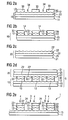
- FIGS. 3a to 3c show sectional views like Fig. 2 , in which Fig. 3a the procedural stage of Fig. 2b corresponds and Fig. 3b the procedural stage of Fig. 2e equivalent.
- the first security element partial element 10 consists of the first carrier substrate 11 with a gold-colored metallization 12.
- first functional regions 13 are formed, as in the context With Fig. 2 explained.
- the second security element subelement 20 consists of the second carrier substrate 21 with a silver-colored metallization 22 thereon. How out Fig. 3a can be seen, the metallization 22 is not formed over the entire surface, but covers the carrier substrate 21 only partially.
- the composite 5 of the first security element partial element 10 and the second security element partial element 20 not all the resist areas 32 are covered with silver-colored metallization 22.
- Fig. 3b After bonding and separating the second carrier substrate 21 results in the Fig. 3b shown construction.
- a viewer sees here in the transmitted light view a line pattern, as in Fig. 1a in the front-side reflected light view (through the first support substrate 11), a gold-colored line pattern (the first functional areas 13), and in the back-elevational view a line pattern of silver-colored lines (the second functional areas 23) and gold-colored lines (represented by the colorless Resist visible through first functional areas 13).
- Holographic motifs as in the security element of Fig. 2 are not recognizable here, since no recuper proposedn with diffraction structure are provided.
- Fig. 3c shows the security element after coating with a protective layer 26.
- the protective layer 26 covers the second functional areas 23 and fills the recesses 3 at least partially.
- FIGS. 4a to 4c show sectional views like the FIGS. 3a to 3c , ie process stages in the production of the security element, as related to Fig. 2d and Fig. 2e were explained.
- the first security element partial element 10 consists of a transparent carrier substrate 11 with a gold-colored metallization 12, in which first functional regions 13 are formed. Resist areas 33 are located above the first functional areas 13, which are congruent with them. The resist areas 33 consist of colorless resist lacquer.
- the second security element subelement 20 consists of the second carrier substrate 21 with a functional layer 22 of black color (for example microlith black from Ciba in ethyl acetate), the black color being printed not on the carrier substrate but on an adhesion-reducing layer 28 for better removability ,
- the adhesion reducing layer 28 is an aluminum metallization of the film 21.
- the first security element subelement 10 and the second security element subelement 20 are assembled into a composite 5, as in FIG Fig. 4a shown.
- the functional layers 12 and 22 connect at the locations where resist areas 33 are located between them.
- the black color adheres to the resist areas 33 and is removed in the remaining areas. You get the in Fig. 4b shown construction.
- a coating with a layer with Farbkipp protagonist for example, a liquid crystal layer 27, in particular a layer of cholesteric liquid crystalline material.
- the security element 1 coated with the liquid crystal layer 27 is shown in FIG Fig. 4c shown.
- a viewer sees a line pattern in the transmitted-light view, a gold-colored line pattern, namely, the first functional areas 13 in the front-side reflected light view (through the transparent support substrate 11), and a color shift-effect line pattern in the rear-side reflected light view.
- the color-shift effect is visible only in the areas that are above the second functional areas 23 of black color. In the other areas, the color-shift effect is not or only very slightly visible for lack of contrast.
- the gold-colored metallization 12 can of course also a silver-colored metallization 12 of z. As chrome or aluminum may be provided so that the viewer perceives in the front side incident light view (through the transparent support substrate 11 through) a silver line pattern.
- a black printing ink it is also advantageous to use a dark functional ink, for example a magnetic ink.
- a dark functional ink for example a magnetic ink.
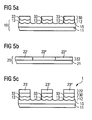
- FIG. 5 a further embodiment of a security element 1 according to the invention is shown.
- the in Fig. 5a shown construction of the first security element partial element 10 is identical to that in Fig. 2b shown construction of the first security element partial element 10th
- Fig. 5b shows a section through the second security element sub-element 20, which consists in this embodiment of a support substrate 21 and a multi-colored motif layer 22.
- the multicolor motif layer consists, for example, of differently colored partial areas 22 ', 22 "and 22"', which together form a geometric or figurative representation.
- the second motif layer 22 is printed, for example.
- Fig. 5c shows the security element 1 after the in Fig. 5a shown first security element subelement and the in Fig. 5b shown second security element sub-element has been assembled into a composite 5 and the second carrier substrate 21 has been separated.
- a viewer recognizes again a line pattern in the transmitted-light view, a holographic motif (generated by the first functional areas 13 with hologram structure information) in the front-side incident light view, and a multicolored motif (generated by the differently-colored second functional areas 23 ') in the rear incident light view. , 23 ", 23"').
- the multicolored motif can be created by using the in Fig.
- the coating 22 may in each case only be partially formed. Otherwise arise second functional areas 23 ', 23 "and 23"' with mixed colors.
- a colored resist can be used.
- a colored resist coating in which only a portion of the resist areas 33 is bonded to a differently colored motif layer 22, likewise leads to a multicolored motif (recognizable in the backside incident light view). It is conceivable furthermore, as already related to Fig. 3 mentioned, the use of resists with different colors, which can also be obtained interesting and difficult to forge security elements.
- Fig. 1b shown view of a security element according to the invention is obtained, if the in Fig. 5c seen safety element in view of the second functional layer 22, wherein the functional areas 23 in the in Fig. 1b
- the area designated 6 is the same color as the ground against which the security element is viewed.
- the remaining functional areas 23 have a color which stands out against the ground, while in the area 6 the motif of the second functional layer 22 is practically imperceptible in plan view.
- the area 6 would have to be formed as a white functional layer.
- a protective layer is applied thereto.
- colored resist coatings are generally less preferred over colorless resist coatings because the dye content affects their adhesion.
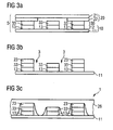
- FIGS. 6a to 6d show the production of a further embodiment of a security element 1 according to the invention
- Fig. 6a a section through the first security element part element 10 is shown. It consists of the first carrier substrate 11, an embossing lacquer layer 15 with diffraction structure 15 'and a first functional layer 12, consisting of a metallization, which covers partial regions of the embossing lacquer layer 15.
- a colored resist 30 is applied, wherein the resist areas 33 partially overlap the metallized areas 12, ie, the resist is located partly on the metallization and partly directly on the embossing lacquer layer. If the metallization not protected by resist areas 33 is removed, the security element subelement is obtained Fig.
- FIG. 6b shows how a second security element sub-element, consisting of a carrier substrate 21, which is partially coated with a color layer 22, with the security element subelement of Fig. 6b is glued. After peeling off the film 21, the security element with the in Fig. 6d shown construction.
- a viewer who in the Fig. 6d Viewed safety element viewed in transmitted light, recognizes contour sharp lines with recesses in between.
- the hologram motif and additionally colored areas can be seen, as above Fig. 6b described.
- the metallized areas 13 are no longer recognizable, since they are covered exactly by colored resist or additionally by the colored second functional areas 23. From this side you can see a multicolored motif in the colors of the resist and the second functional layer.
- the second functional layer can form a multicolored motif so that the recognizable overall motif has more than two colors.
- resist coatings of different colors can be used, which also allows a very large number of different-colored motifs, which significantly increases the security against counterfeiting.
- FIG. 3 illustrates an alternative method sequence in the production of a security element 1 according to the invention, in which instead of the one described in FIG Fig. 2c shown second security element sub-element 20 in Fig. 7a shown second security element sub-element 20 is used.
- Fig. 7a shows a section through the second security element sub-element 20, with the in Fig. 2b shown first security element sub-element 10 is to be combined.
- This in Fig. 7a shown second security element sub-element 20 is a metal donut sheet without embossing, which has a second support substrate 21 and a metallization 220 produced thereon.
- Fig. 7b shows how the first security element subelement 10 Fig. 2b and the second security element subelement 20 Fig. 7a be assembled into a composite 5.
- the second carrier substrate 21 is peeled off, for example by a separating winding.
- the result is in Fig. 7c shown. Only the areas 23 of the metallization 220 that were in contact with resist areas 33 were glued to the first security element subelement 10. These regions are regions 23 suitable for forming diffraction patterns, which represent an exact reproduction of the pattern of the resist regions 33.
- the remaining regions of the metallization 220 were removed together with the second carrier substrate, while the regions 23 of the metallization 220 bonded to the resist regions 33 were pulled off the carrier substrate.
- Fig. 7c formed, suitable for forming diffraction structures suitable areas 23, for example, by embossing to metallized diffraction structures.
- the result is in Fig. 7d shown.
- the lines 4 are each carriers of a diffraction structure.
- the diffraction structures may be, for example, hologram structures, wherein preferably present in the first functional areas 13 and the second functional areas 23 different hologram structures.
- the method according to the invention allows a register-accurate and edge-sharp formation of very fine structures with a width or a diameter of about 50 ⁇ m or less.
- the present invention has always been described in the context of a transparent or translucent first carrier substrate.
- an opaque first carrier substrate whereby, however, the negative writing becomes poorly recognizable, and only one of the two reflected light views is clearly recognizable, namely the view referred to above as rear-side incident light view.
- An opaque carrier substrate 11 is therefore less preferred.
- the first security element sub-element 10 so in the example in Fig. 2a shown form are glued to the second security element sub-element 20.
- the pattern of the resist layer 30 is accurately reproduced only in the second functional layer 22, which, however, can also give very satisfactory results with highly visible negative writing, for example, when the first functional layer 12 is formed as a transparent color.
- a first security element partial element 10 with congruent first functional areas 13 and resist areas 33 can be glued to a second security element partial element 20 whose second functional layer 22 already has a pattern, but which does not match the pattern of the first functional layer 13 and the Resist regions 33 matches.
- the first functional areas 13 and the resist areas 33 are a line pattern as in FIG Fig. 1a forming a bond with a second functional layer 22 having a perpendicular line pattern of parallel lines, this results in a security element 1 with punctiform second functional areas 23.
- the second functional areas 23 are then like pearls on a string on the through the first functional areas lines "strung". In supervision of the second functional areas, the viewer recognizes lines with dots.
- first functional layer 12 has functional regions 13 in the form of circular concentric lines.
- the first functional layer 12 is printed with a resist layer 30 in the form of parallel straight lines 33.
- a second security element partial element 20 is glued thereon, in the second functional layer 22 of which a pattern of functional areas 23 in the form of likewise parallel straight lines is formed, which form an angle with the resist area lines 33.
- the second functional areas 23 stick together with the first security element partial element 10 in the areas in which they come to lie over resist areas 33.
- a viewer then, after separating the second carrier substrate 21, sees the circular one Pattern of the first functional layer with punctiform regions formed by the second functional layer. If a colored resist is used, the resist lines 33 are additionally recognizable.
- All security elements according to the invention have in common that two of their functional layers are bonded directly to one another by means of a resist, wherein at least the pattern of a functional layer, preferably also the pattern of the other functional layer, is at least partly due to the pattern of the resist layer.
- the security elements according to the invention can be provided in the form of transfer materials, ie films or tapes having a multiplicity of finished security elements prepared for the transfer.
- the layer structure of the later security element is prepared on a carrier material in the reverse order in which the layer structure is later to be stored on a valuable object, wherein the layer structure of the security element in continuous form or already in the final outline form used as security element on the Carrier material can be prepared.
- a hot melt adhesive is used for this purpose.
- an adhesive layer can be provided for transfer either only in the areas of the security element to be transferred, or the adhesive is activated only in the areas to be transferred.
- the carrier material of the transfer elements is usually deducted from the layer structure of the security elements during or after their transfer to the valuable article.
- a separating layer release layer
- the carrier material can also remain on the transmitted security element.
- the security elements according to the invention can be used to authenticate goods of any kind.
- they are used to authenticate value documents, for example banknotes, checks or identity cards.
- they can be arranged on a surface of the value document or be completely or partially embedded in the value document.
- they are used in value documents hole hole hole.
- the advantages of the security elements according to the invention with transparent carrier substrates and from both sides of the value document to be considered, carefully matched motifs, can be particularly beautiful. Even negatives with the finest structures and sub-patterns can be clearly recognized in transmitted light. You are in the achievable according to the invention precision of a counterfeiter practically imitated.
- the security elements of the invention always contain at least two layers of adhesive, d. H. they contain an adhesive resist layer and are bonded with an adhesive layer to the valuable object to be secured. If, for the bonding of the security element to the object of value, an adhesive which is similar in terms of its chemical and physical properties to the resist in the layer structure of the security element, the layer structure of the security element is always destroyed during detachment attempts.
Description
Die Erfindung betrifft ein Verfahren zur Herstellung eines Sicherheitselements mit zwei zueinander gepasserten Motivschichten, insbesondere Motivschichten mit im Durchlicht und bevorzugt auch im Auflicht visuell erkennbaren Zeichen, ein mittels des Verfahrens erhältliches Sicherheitselement, das als Transferelement ausgebildete Sicherheitselement, die Verwendung des Sicherheitselements bzw. Transferelements zur Produktsicherung, einen mit dem Sicherheitselement ausgestatteten Wertgegenstand sowie ein Verfahren zur Herstellung eines derartigen Wertgegenstands.The invention relates to a method for producing a security element having two mutually matched motif layers, in particular motif layers having visible in transmitted light and preferably also in incident light sign, a security element available by the method, the security element formed as a transfer element, the use of the security element or transfer element for Product security, a valuable item equipped with the security element and a method for producing such a valuable item.
Wertgegenstände, insbesondere Wertdokumente wie Banknoten, Aktien, Ausweise, Kreditkarten, Urkunden, Schecks, und andere fälschungsgefährdete Papiere, wie Ausweisdokumente unterschiedlichster Art, aber auch Markenartikel und Verpackungen von Markenartikeln werden zur Absicherung gerne mit Sicherheitselementen ausgestattet, die eine Überprüfung ihrer Echtheit ermöglichen und gleichzeitig als Schutz vor unerlaubter Reproduktion dienen. Die Sicherheitselemente können beispielsweise die Form von Sicherheitsfäden oder Aufklebern oder irgendeine andere in einen Wertgegenstand oder ein Sicherheitspapier einbringbare oder aufbringbare Form haben, wobei ein "Wertgegenstand" im Sinne der vorliegenden Erfindung jeder gegen Fälschung sicherungswerte Gegenstand ist, insbesondere ein Wertdokument, während ein "Sicherheitspapier" die noch nicht umlauffähige Vorstufe zu einem Wertdokument darstellt.Valuables, in particular documents of value such as banknotes, shares, identity cards, credit cards, certificates, checks, and other forgery-prone papers, such as identity documents of various kinds, but also branded goods and packaging of branded goods are often equipped with security elements to secure their authenticity and at the same time serve as protection against unauthorized reproduction. The security elements may, for example, take the form of security threads or stickers or any other form insertable or attachable to a valuable article or security paper, a "valuable article" within the meaning of the present invention being any objectionable to counterfeiting, in particular a value document, while a "security paper "represents the precursor to a value document, which is not yet ready for use.
Sicherheitselemente sind typischerweise mehrschichtige Elemente mit mehreren Funktionsschichten. Funktionsschichten sind ganz allgemein Schichten, die irgendwelche Eigenschaften aufweisen, die visuell oder maschinell nachgewiesen werden können. Funktionsschichten enthalten daher beispielsweise Farbstoffe, Lumineszenzstoffe, thermochrome Stoffe, Flüssigkristalle, Interferenzpigmente, elektrisch leitfähige Stoffe, magnetische Stoffe, lichtbeugende oder lichtbrechende Strukturen oder Kombinationen davon. Die Funktionsschichten sind meist als geometrische oder figürliche Muster bzw. Motive ausgebildet, d. h. es gibt innerhalb einer Schicht Funktionsbereiche mit der nachweisbaren Eigenschaft (beispielsweise Lumineszenz) und Aussparungen dazwischen. Werden mehrere Funktionsschichten übereinander angeordnet, ist es in der Regel wünschenswert, dass die Funktionsbereiche und die Aussparungen in den einzelnen Funktionsschichten exakt registerhaltig, d. h. mit hoher Passergenauigkeit, und mit konturenscharfen Kanten zwischen den Funktionsbereichen und den Aussparungen übereinander ausgebildet sind. Auf diese Weise kann eine Funktionsschicht unter einer anderen versteckt werden, beispielsweise magnetische Stoffe unter einer Farbschicht, oder es können Sicherheitselemente mit mehreren Funktionsschichten und "Negativschrift" hergestellt werden.Security elements are typically multilayer elements with multiple functional layers. Functional layers are generally layers that have any properties that can be detected visually or by machine. Functional layers therefore contain, for example Dyes, luminescent substances, thermochromic substances, liquid crystals, interference pigments, electrically conductive substances, magnetic substances, light-diffractive or refractive structures or combinations thereof. The functional layers are usually designed as geometric or figurative patterns or motifs, ie there are functional areas within a layer with the detectable property (for example luminescence) and recesses in between. If a plurality of functional layers are arranged one above the other, it is generally desirable for the functional regions and the recesses in the individual functional layers to be formed exactly in register, ie with high register accuracy, and with contour-sharp edges between the functional regions and the recesses. In this way, one functional layer can be hidden under another, for example magnetic substances under a colored layer, or security elements with multiple functional layers and "negative writing" can be produced.
Sicherheitselemente mit Negativschrift weisen ein transparentes Substrat mit mindestens einer nicht transparenten Beschichtung, die Aussparungen (die Negativschrift) aufweist, auf. Diese Aussparungen können beliebige Formen haben, beispielsweise Buchstaben, Zahlen oder Muster irgendwelcher Art, insbesondere Linienmuster. Der in dieser Anmeldung verwendete Begriff "Negativschrift" umfasst demnach Aussparungen beliebiger Form, also jede Nicht-Vollflächigkeit in einer nicht transparenten Beschichtung. Je transparenter, d. h. je lichtdurchlässiger, das Trägersubstrat ist, desto ausgeprägter ist der Kontrast zwischen beschichteten und nicht beschichteten Bereichen. Bei sehr transparenten Substraten ist die Negativschrift im Auflicht deutlich erkennbar, bei weniger transparenten Substraten nur im Durchlicht. Weist ein derartiges Sicherheitselement mit Negativschrift zwei unterschiedliche Funktionsschichten auf, beispielsweise ein Motiv in Form einer goldfarbenen metallischen Beschichtung und darauf dasselbe Motiv als rote Druckfarbe, so erscheint dieses Motiv dem Betrachter von der einen Seite her gesehen goldfarben, von der anderen Seite her gesehen rot.Negative-type security elements comprise a transparent substrate having at least one non-transparent coating having recesses (the negative writing). These recesses may have any shapes, such as letters, numbers or patterns of any kind, especially line patterns. The term "negative writing" used in this application accordingly comprises recesses of any shape, ie any non-solidity in a non-transparent coating. The more transparent, ie the more translucent, the carrier substrate is, the more pronounced is the contrast between coated and uncoated regions. In the case of very transparent substrates, the negative writing is clearly recognizable in incident light, with less transparent substrates only in transmitted light. Has such a security element with negative writing two different functional layers, for example, a motif in the form of a gold-colored metallic coating and thereupon the same motif as a red printing ink, so this motif appears to the viewer from one side seen in gold, seen from the other side red.
Derartige mehrschichtige Motive sind aufgrund der erforderlichen hohen Passergenauigkeit schwer nachahmbar. Insbesondere Motive mit Negativschriften bieten einen guten Fälschungsschutz, da im Durchlicht Ungenauigkeiten bei der Herstellung besonders leicht erkennbar sind, und "primitive" Fälschungsversuche, wie etwa das Kopieren mit Farbkopierern, auch für das ungeübte Auge sofort erkennbar sind.Such multilayer motifs are difficult to imitate due to the required high registration accuracy. In particular, subjects with negative fonts provide good protection against counterfeiting, since in the transmitted light inaccuracies in the production are particularly easily recognizable, and "primitive" counterfeiting attempts, such as copying with color copiers, even for the untrained eye are immediately recognizable.
Die Fälschungssicherheit ist umso höher, je feiner die Strukturen in den Funktionsschichten mit den zueinander gepasserten Motiven sind. Feinste Strukturen konturenscharf und im perfekten Register zueinander auszubilden stellt allerdings auch für autorisierte Hersteller eine Herausforderung dar. Es sind eine Reihe von Verfahren bekannt, die es ermöglichen sollen, Aussparungen in mehreren übereinander liegenden Funktionsschichten passergenau, d. h. deckungsgleich in allen Schichten, auszubilden.The tamper-proof is the higher the finer the structures in the functional layers are with the matched-to-each other motifs. Finely contoured structures and forming the perfect register with each other, however, also pose a challenge for authorized manufacturers. A number of methods are known which are intended to enable recesses in a plurality of superimposed functional layers to be registered precisely. H. congruent in all layers, train.
Aus
Die genannten Verfahren funktionieren zufriedenstellend, solange keine sehr feinen Strukturen auszubilden sind. Das Problem der Ausbildung deckungsgleicher Muster und Negativschriften in mehreren Schichten mit hoher Passergenauigkeit und Konturenschärfe ist jedoch insbesondere für feine Strukturen bisher nicht zufriedenstellend gelöst.The methods mentioned work satisfactorily, as long as no very fine structures are to be formed. However, the problem of forming congruent patterns and negatives in multiple layers with high registration accuracy and contour sharpness is not yet satisfactorily resolved, especially for fine structures.
Aufgabe der vorliegenden Erfindung ist es daher, ein Verfahren zur Herstellung von Sicherheitselementen bereitzustellen, das es erlaubt, in zwei übereinander liegenden Schichten zumindest bereichsweise deckungsgleiche Muster bzw. Motive auszubilden.The object of the present invention is therefore to provide a method for the production of security elements, which makes it possible to form congruent patterns or motifs in two superimposed layers at least in regions.
Aufgabe der vorliegenden Erfindung ist es insbesondere, ein derartiges Verfahren bereitzustellen, mit dem zumindest bereichsweise deckungsgleiche Muster bzw. Motive konturenscharf und mit hoher Passergenauigkeit ausgebildet werden können.The object of the present invention is, in particular, to provide such a method, with which congruent, at least in some areas Patterns or motifs sharp contours and can be formed with high registration accuracy.
Aufgabe der vorliegenden Erfindung ist es darüber hinaus, ein derartiges Verfahren bereitzustellen, wobei die auszubildenden Muster bzw. Motive sehr feine Strukturen aufweisen.It is also an object of the present invention to provide such a method, wherein the patterns or motifs to be formed have very fine structures.
Aufgabe der vorliegenden Erfindung ist es auch, ein Sicherheitselement mit zwei Motivschichten mit einander entsprechenden Mustern bzw. Motiven, die eine hohe Passergenauigkeit aufweisen, bereitzustellen.Object of the present invention is also to provide a security element with two motif layers with corresponding patterns or motifs, which have a high registration accuracy.
Aufgabe der vorliegenden Erfindung ist es ferner, ein derartiges Sicherheitselement bereitzustellen, bei dem die Motivschichten sehr feine Strukturen aufweisen und konturenscharf ausgebildet sind.It is also an object of the present invention to provide such a security element in which the motif layers have very fine structures and are of sharp contours.
Aufgabe der vorliegenden Erfindung ist es darüber hinaus, derartige Sicherheitselemente in Form von Transferelementen bereitzustellen, sowie Sicherheitspapiere und Wertgegenstände mit den erfindungsgemäßen Sicherheitselementen bzw. Transferelementen und Verfahren zur Herstellung der Sicherheitspapiere und der Wertgegenstände bereitzustellen.It is also an object of the present invention to provide such security elements in the form of transfer elements, and to provide security papers and valuables with the security elements or transfer elements according to the invention and methods for producing the security papers and the valuables.
Die Aufgaben werden gelöst durch das Verfahren zur Herstellung eines Sicherheitselements mit den in Anspruch 1 angegebenen Merkmalen, durch das Sicherheitselement mit den in Anspruch 9 angegebenen Merkmalen, durch das Transfermaterial mit den in Anspruch 13 angegebenen Merkmalen, durch das Sicherheitspapier bzw. den Wertgegenstand gemäß Anspruch 14 und durch das Verfahren gemäß Anspruch 15.The objects are achieved by the method for producing a security element having the features specified in
Spezielle Ausführungsformen der vorliegenden Erfindung sind in den jeweiligen abhängigen Ansprüchen angegeben.Specific embodiments of the present invention are set forth in the respective dependent claims.
Der Grundgedanke der vorliegenden Erfindung besteht darin, eine klebefähige Resistschicht zu verwenden, um in zwei Funktionsschichten deckungsgleiche Muster auszubilden. Dazu wird eine Resistschicht in Form des gewünschten Musters auf eine erste Funktionsschicht aufgetragen. Das Muster wird in der ersten Funktionsschicht exakt reproduziert, indem die nicht durch den Resist geschützten Bereiche der ersten Funktionsschicht entfernt werden. Anschließend wird das Muster in der zweiten Funktionsschicht reproduziert, indem die zweite Funktionsschicht mit dem Resist verklebt wird. Die Verklebung findet nur in den Bereichen statt, in denen die zweite Funktionsschicht Kontakt mit dem Resist hat. Die nicht verklebten Bereiche der zweiten Funktionsschicht werden dann entfernt, während die verklebten Bereiche nicht entfernt werden können, wodurch in der zweiten Funktionsschicht eine exakte Reproduktion des Musters der Resistschicht und der ersten Funktionsschicht entsteht.The basic idea of the present invention is to use a stickable resist layer to form congruent patterns in two functional layers. For this purpose, a resist layer in the form of the desired pattern is applied to a first functional layer. The pattern is exactly reproduced in the first functional layer by removing the non-resist protected areas of the first functional layer. Subsequently, the pattern in the second functional layer is reproduced by adhering the second functional layer to the resist. The bonding takes place only in the areas in which the second functional layer has contact with the resist. The non-bonded regions of the second functional layer are then removed, while the bonded regions can not be removed, whereby an exact reproduction of the pattern of the resist layer and the first functional layer is produced in the second functional layer.
Das erfindungsgemäße Sicherheitselement wird aus zwei Teilelementen hergestellt. Ein erstes Teilelement besteht mindestens aus einem Trägersubstrat und einer Funktionsschicht, bevorzugt mit Aussparungen darin. Weitere Schichten können vorhanden sein. Die Funktionsschicht kann auch aus mehreren Einzelschichten aufgebaut sein.The security element according to the invention is produced from two partial elements. A first subelement consists at least of a carrier substrate and a functional layer, preferably with recesses therein. Additional layers may be present. The functional layer can also be composed of several individual layers.
Das Trägersubstrat des ersten Sicherheitselement-Teilelements ist bevorzugt eine Folie, beispielsweise aus Polypropylen, Polyethylen, Polystyrol, Polyester, insbesondere Polycarbonat oder Polyethylenterephthalat. Transparente oder transluzente Folien sind besonders bevorzugt. Bei einer Verwendung derartiger Folien können die passergenau ausgebildeten Aussparungen in den einzelnen Funktionsschichten deutlich als Negativschrift erkannt werden.The carrier substrate of the first security element partial element is preferably a film, for example made of polypropylene, polyethylene, polystyrene, polyester, in particular polycarbonate or polyethylene terephthalate. Transparent or translucent films are particularly preferred. When using such films, the register formed recesses in the individual functional layers are clearly recognized as negative writing.
Ein großer Vorteil des erfindungsgemäßen Verfahrens besteht darin, dass es ohne einen Belichtungsschritt auskommt, da der Resist in Form des gewünschten Motivs mittels an sich bekannter Verfahren aufgebracht werden kann. Das erfindungsgemäße Verfahren ermöglicht demnach die Herstellung präzise gepasserter Funktionsschichten ohne Belichtungsschritte, wobei die erfindungsgemäßen Sicherheitselemente dennoch durch eine sehr große Fälschungssicherheit charakterisiert sind.A great advantage of the method according to the invention is that it does not require an exposure step, since the resist in the form of the desired motif can be applied by means of methods known per se. Accordingly, the method according to the invention makes it possible to produce precisely calibrated functional layers without exposure steps, wherein the security elements according to the invention are nevertheless characterized by a very high security against counterfeiting.
Zur Herstellung des ersten Sicherheitselement-Teilelements wird zunächst auf dem Trägersubstrat eine Funktionsschicht ausgebildet. Die Funktionsschicht kann grundsätzlich von beliebiger Art sein, wie sie bei Sicherheitselementen verwendet wird. Als Beispiele seien genannt Metallschichten aus beispielsweise Aluminium, Eisen, Kupfer, Gold, Nickel, etc., Metalllegierungen, oder Schichten aus Metalleffektfarben, Schichten mit Farbpigmenten oder Fluoreszenzpigmenten, Flüssigkristall-Schichten, Beschichtungen mit Farbkippeffekt, Schichtkombinationen wie beispielsweise eine mit einer bestimmten Farbe unterlegte Schicht mit Farbkippeffekt, Schichten mit maschinell nachweisbaren Merkmalen, beispielsweise mit Magnetpigmenten, die gegebenenfalls unter einer Deckschicht versteckt werden können.To produce the first security element partial element, a functional layer is first formed on the carrier substrate. The functional layer can basically be of any type as used in security elements. Examples which may be mentioned are metal layers of, for example, aluminum, iron, copper, gold, nickel, etc., metal alloys or layers of metallic effect paints, layers with color pigments or fluorescent pigments, liquid crystal layers, coatings with a color shift effect, layer combinations such as one with a specific color Layer with color shift effect, layers with machine-detectable features, for example, with magnetic pigments, which may optionally be hidden under a cover layer.
Die Aufbringung der Funktionsschichten erfolgt nach bekannten Verfahren, die für die jeweilige Funktionsschicht geeignet sind, beispielsweise durch physikalische Dampfabscheidung (PVD) bei Metallen oder durch Aufdrucken bei Farbpigmenten oder Fluoreszenzpigmenten. Die Auftragung kann vollflächig oder nur in Teilbereichen erfolgen.The application of the functional layers is carried out by known methods that are suitable for the respective functional layer, for example by physical vapor deposition (PVD) in metals or by printing on color pigments or fluorescent pigments. The application can be made over the entire area or only in partial areas.
Die Funktionsschicht kann direkt auf dem Trägersubstrat ausgebildet werden, oder es können eine oder mehrere Zwischenschichten vorgesehen werden. Für manche Funktionsschichten sind Zwischenschichten zwingend erforderlich, beispielsweise wenn es sich bei dem Motiv der Funktionsschicht um ein metallisiertes Hologramm, Kinegram, Pixelgramm oder eine sonstige metallisierte Beugungsstruktur handelt. In einem solchen Fall wird zuerst eine Prägelackschicht aufgetragen und in die Prägelackschicht, vor oder nach der Metallisierung, die gewünschte diffraktive Struktur eingeprägt. Auch bei Flüssigkristall-Schichten ist in der Regel eine Zwischenschicht erforderlich, die für eine passende Orientierung der Flüssigkristalle sorgt. Geeignete Orientierungsschichten können beispielsweise in Prägelackschichten eingeprägten diffraktive Strukturen sein. Alternativ kann gegebenenfalls auch die Trägerfolie geeignet behandelt werden.The functional layer can be formed directly on the carrier substrate, or one or more intermediate layers can be provided. For some functional layers, intermediate layers are absolutely necessary, for example if the motif of the functional layer is a metallized hologram, kinegram, pixelgram or another metallized diffraction structure. In such a case, first an embossing lacquer layer is applied and embossed into the embossing lacquer layer, before or after the metallization, the desired diffractive structure. In the case of liquid-crystal layers as well, an intermediate layer is generally required which ensures a suitable orientation of the liquid crystals. Suitable orientation layers can be, for example, diffractive structures embossed in embossing lacquer layers. Alternatively, if appropriate, the carrier film can also be suitably treated.
Gemäß einer bevorzugten Ausführungsform der vorliegenden Erfindung ist eine der Motivschichten eine metallisierte Beugungsstruktur wie ein metallisiertes Hologramm, besonders bevorzugt ist auch eine weitere Motivschicht eine metallisierte Beugungsstruktur, wie ein metallisiertes Hologramm. Wenn im Folgenden von Hologrammen gesprochen wird, versteht es sich, dass dasselbe auch für andere Beugungsstrukturen und Brechungsstrukturen gilt sowie für sogenannte "Mattstrukturen" (Gitterbilder mit achromatischen Gitterbereichen), wie sie z. B. in der
Wie oben erwähnt, ist im Falle von Hologrammen eine Prägelackschicht vorzusehen, die die gewünschte Strukturinformation eingeprägt enthält. Die Strukturinformation wird beim Verkleben mit dem zweiten Sicherheitselement-Teilelement mit übertragen. Hologramme bzw. Strukturinformationen ganz allgemein können in den Funktionsschichten eines erfindungsgemäßen Sicherheitselements gleich oder verschieden sein. Materialien für Prägelackschichten sind einem Fachmann bekannt. Geeignete Prägelacke sind beispielsweise offenbart in
Auf die Funktionsschicht des ersten Sicherheitselement-Teilelements wird in einem weiteren Schritt ein Resist aufgetragen. Unter einem Resist wird im Rahmen der vorliegenden Anmeldung jedes Material verstanden, das die Durchführung des erfindungsgemäßen Verfahrens zur Herstellung eines erfindungsgemäßen Sicherheitselements gestattet. Insbesondere muss ein solches Resistmaterial Bereiche der ersten Funktionsschicht vor der Entfernung schützen können, um nur in den nicht geschützten Bereichen erste Aussparungen in der ersten Funktionsschicht zu erzeugen. Des Weiteren muss das Resistmaterial eine ausreichende Klebefähigekeit aufweisen, um erste und zweite Funktionsbereiche miteinander zu verkleben. Demnach sind als Resistmaterialien Verbindungen geeignet, die Bereiche der ersten Funktionsschicht vor Entfernung schützen können und ausreichend klebefähig sind. Geeignete Resistmaterialien sind daher z.B. verschiedene thermoplastische Materialien. Bevorzugt werden thermoplastische Resistlacke verwendet. Beispiele für erfindungsgemäße Resistlacke werden weiter unten angeführt.A resist is applied to the functional layer of the first security element partial element in a further step. In the context of the present application, a resist is understood to mean any material which allows the process according to the invention to be carried out to produce a security element according to the invention. In particular, such a resist material must be able to protect regions of the first functional layer from removal in order to produce first recesses in the first functional layer only in the unprotected regions. Furthermore, the resist material must have sufficient adhesiveness to bond first and second functional areas together. Accordingly, suitable as resist materials are compounds which can protect areas of the first functional layer from removal and are sufficiently adhesive. Suitable resist materials are therefore e.g. different thermoplastic materials. Preference is given to using thermoplastic resist coatings. Examples of resist coatings according to the invention are given below.
Der Resist wird bevorzugt in Form des gewünschten Musters aufgetragen, beispielsweise aufgedruckt. Dem Fachmann sind dafür geeignete Druckverfahren bekannt.The resist is preferably applied in the form of the desired pattern, for example printed. The person skilled in the art suitable printing methods are known.
Anschließend wird die Funktionsschicht des ersten Sicherheitselement-Teilelements, d. h. die erste Funktionsschicht, strukturiert, d. h. das Muster der Resistschicht wird in die erste Funktionsschicht übertragen. Die Übertragung geschieht in der Weise, dass die nicht durch Resist geschützten Bereiche der ersten Funktionsschicht entfernt werden, bei metallischen Funktionsschichten beispielsweise durch Ätzmittel wie Laugen oder Säuren, bei Druckfarben beispielsweise durch Auswaschen mit geeigneten Lösungsmitteln. Geeignete Verfahren sind dem Fachmann bekannt. Das erste Sicherheitselement-Teilelement besitzt nun ein Muster, das deckungsgleiche Funktionsbereiche und Resistbereiche und ebenfalls deckungsgleiche Aussparungen zwischen diesen Bereichen aufweist. Das Muster kann beispielsweise eine Codierung oder ein geometrisches oder figürliches Motiv bilden.Subsequently, the functional layer of the first security element partial element, ie the first functional layer, is patterned, ie the pattern of the resist layer is transferred into the first functional layer. The transfer happens in such a way that the not protected by resist areas of the first functional layer are removed in metallic functional layers, for example, by etchants such as alkalis or acids in printing inks, for example by washing with suitable solvents. Suitable methods are known to the person skilled in the art. The first security element subelement now has a pattern that has congruent functional areas and resist areas and also congruent recesses between these areas. The pattern may, for example, form an encoding or a geometric or figurative motif.
Als nächstes wird das zweite Sicherheitselement-Teilelement hergestellt.Next, the second security element subelement is manufactured.
Das zweite Sicherheitselement-Teilelement weist, wie das erste Sicherheitselement-Teilelement, mindestens zwei Schichten auf, nämlich ein Trägersubstrat und eine darauf ausgebildete Funktionsschicht. Zusätzlich können weitere Schichten vorhanden sein, bzw. müssen vorhanden sein, wie vorstehend für das erste Sicherheitselement-Teilelement ausgeführt wurde.The second security element subelement has, like the first security element subelement, at least two layers, namely a carrier substrate and a functional layer formed thereon. In addition, additional layers may be present, or must be present, as stated above for the first security element subelement.
Generell gilt für die Materialien, den Aufbau und die Herstellung der Schichten des zweiten Sicherheitselement-Teilelements dasselbe wie für das erste Sicherheitselement-Teilelement, wobei jedoch zu beachten ist, dass in der Funktionsschicht, oder der Funktionsschichtfolge, keine Aussparungen ausgebildet werden. Die Aussparungen werden erst durch Zusammenwirken mit dem ersten Sicherheitselement-Teilelement bzw. der Resistschicht darauf erzeugt. Außerdem wird das Trägersubstrat des zweiten Sicherheitselement-Teilelements später zusammen mit Teilen der Funktionsschicht des zweiten Sicherheitselement-Teilelements abgetrennt, z. B. durch Trennwicklung abgezogen (z. B. den Teilen der Funktionsschicht, die in dem zusammengesetzten Sicherheitselement über Aussparungen in der Funktionsschicht des ersten Sicherheitselement-Teilelements angeordnet sind), während sich das Trägersubstrat von anderen Teilen der Funktionsschicht des zweiten Sicherheitselement-Teilelements (z. B. den Teilen, die in dem zusammengesetzten Sicherheitselement über Funktionsbereichen des ersten Sicherheitselement-Teilelements angeordnet sind), ablösen lassen muss. Daher ist es erforderlich, dass die Funktionsschicht nur eine geringe Haftung an dem Trägersubstrat besitzt.In general, the same applies to the materials, the structure and the production of the layers of the second security element subelement as for the first security element subelement, it being noted, however, that no recesses are formed in the functional layer or the functional layer sequence. The recesses are only produced by cooperation with the first security element subelement or the resist layer thereon. In addition, the carrier substrate of the second security element subelement is later separated together with parts of the functional layer of the second security element subelement, for. B. withdrawn by a separation winding (eg, the parts of the functional layer in the composite security element via recesses in the functional layer of the first Security element sub-element) while the carrier substrate must be peel-off from other parts of the functional layer of the second security-element sub-element (eg, the parts located in the composite security element over functional areas of the first security-element sub-element). Therefore, it is necessary that the functional layer has only a slight adhesion to the carrier substrate.
Die erforderliche geringe Haftkraft wird bei vielen Funktionsschichtmaterialien, insbesondere Metallisierungen, schon alleine dadurch erreicht, dass auf haftvermittelnde Maßnahmen zwischen Trägersubstrat und Funktionsschicht verzichtet wird. Das Treffen haftvermittelnder Maßnahmen zwischen den einzelnen Schichten eines Sicherheitselements ist ansonsten üblich, und die entsprechenden Vorkehrungen einem Fachmann bekannt.The required low adhesion force is already achieved in many functional layer materials, in particular metallizations, by omitting adhesion-promoting measures between the carrier substrate and the functional layer. The meeting of adhesion-promoting measures between the individual layers of a security element is otherwise customary, and the corresponding provisions are known to a person skilled in the art.
Wenn die Haftkraft zwischen Trägersubstrat und Funktionsschicht zu hoch ist, kann sie durch Behandeln des Trägersubstrats mit geeigneten Additiven herabgesetzt werden. Beispielsweise kann das Trägersubstrat mit Wasser und/oder Lösungsmitteln mit oder ohne geeignete Additive abgewaschen werden. Als entsprechende Additive geeignet sind beispielsweise tensidisch wirkende Substanzen, Entschäumer oder Verdicker. Additive können auch in das Trägersubstrat selbst eingebracht werden. Alternativ können unter der Funktionsschicht haftvermindernde Schichten vorgesehen werden. Für die haftvermindernden Schichten werden Materialien gewählt, auf deren Oberflächen bekanntermaßen für gewöhnlich eine relativ schlechte Haftung auftritt, beispielsweise Silikonisierungen, Schichten, die Releaseadditve (z. B. Byk 3500) enthalten, Wachse, ausgehärtete UV-Lacke, Metallisierungen, unbehandelte Folien wie z. B. PET. Durch Abstimmung der Oberflächenenergie-Verhältnisse des Trägersubstrats bzw. der haftvermindernden Schicht und der abzulösenden Funktionsschicht kann eine leichte Ablösbarkeit der Funktionsschicht erreicht und damit das gewünschte Muster in der Funktionsschicht des zweiten Sicherheitselement-Teilelements erzeugt werden.If the adhesive force between the carrier substrate and the functional layer is too high, it can be reduced by treating the carrier substrate with suitable additives. For example, the carrier substrate can be washed off with water and / or solvents with or without suitable additives. Suitable additives are, for example, surface-active substances, defoamers or thickeners. Additives can also be introduced into the carrier substrate itself. Alternatively, adhesion-reducing layers can be provided under the functional layer. For the adhesion reducing layers, materials are selected on the surfaces of which, as is generally known, a relatively poor adhesion occurs, for example siliconizations, layers containing release additive (eg Byk 3500), waxes, cured UV lacquers, metallizations, untreated films, such as, for example , Eg PET. By matching the surface energy ratios of the carrier substrate or adhesion-reducing layer and the functional layer to be detached, an easy detachability of the functional layer can be achieved and thus the desired pattern can be produced in the functional layer of the second security element partial element.
Analoges gilt für gegebenenfalls zwischen dem Trägersubstrat und der Funktionsschicht vorhandene Zwischenschichten, beispielsweise Prägelackschichten für ein Hologramm. Soll eine derartige Prägelackschicht oder sonstige Zwischenschicht zusammen mit dem Trägersubstrat abgezogen werden, muss entsprechend die Haftkraft zwischen der Zwischenschicht und der Funktionsschicht, also beispielsweise zwischen der Prägelackschicht und einer darauf aufgebrachten Metallisierung, gering sein. Im Falle einer zu hohen Haftkraft ist die Zwischenschicht mit den genannten Additiven zu behandeln, oder eine haftvermindernde Schicht vorzusehen.The same applies to any intermediate layers present between the carrier substrate and the functional layer, for example embossing lacquer layers for a hologram. If such an embossing lacquer layer or other intermediate layer is to be taken off together with the carrier substrate, the adhesive force between the intermediate layer and the functional layer, ie for example between the embossing lacquer layer and a metallization applied thereon, must be correspondingly low. If the adhesive force is too high, the intermediate layer should be treated with the above-mentioned additives or an adhesion-reducing layer should be provided.
Wird eine Behandlung des Trägersubstrats oder einer Zwischenschicht mit haftverringernden Additiven vorgenommen, können nach dem Abtrennen des Trägersubstrats bzw. der Zwischenschicht Reste der Additive auf der Funktionsschicht verbleiben. Diese können normalerweise einfach mit einer wässrigen Lösung, deren pH geeignet eingestellt ist und die gegebenenfalls auch Tenside enthalten kann, weggewaschen werden. Auch eine Wäsche mit Lösungsmitteln ist möglich. In hartnäckigen Fällen kann auch mit Hochdruckdüsen und/oder mechanischer Unterstützung (Filze, Bürsten) gearbeitet werden, doch dies ist für gewöhnlich nicht erforderlich. Geringe Additivreste können auch mittels einer Koronabehandlung "weggebrannt" werden. Im übrigen kann in vielen Fällen auch ganz auf eine Entfernung von Additivresten verzichtet werden. Geeignete formulierte Schutzlacke können auch auf "additivbelasteten" Funktionsschichten ausreichend haften.If a treatment of the carrier substrate or an intermediate layer with adhesion-reducing additives is carried out, residues of the additives can remain on the functional layer after the carrier substrate or the intermediate layer has been separated off. These can normally be washed away simply with an aqueous solution whose pH is suitably adjusted and which may optionally also contain surfactants. Even a laundry with solvents is possible. In persistent cases, high-pressure nozzles and / or mechanical support (felts, brushes) can be used, but this is usually not necessary. Small additive residues can also be "burned away" by means of a corona treatment. Moreover, in many cases can be completely dispensed with a removal of additive residues. Suitable formulated conformal coatings can also adhere adequately to "additive-loaded" functional layers.
Nun werden das erste Sicherheitselement-Teilelement, das eine Funktionsschicht mit Funktionsbereichen und Aussparungen aufweist, und das zweite Sicherheitselement-Teilelement, das eine Funktionsschicht im Wesentlichen ohne Aussparungen aufweist, mit Hilfe der auf den Funktionsbereichen des ersten Sicherheitselement-Teilelements befindlichen Resistschicht miteinander verbunden. Auf die Resistschicht wird das zweite Sicherheitselement-Teilelement so aufgesetzt, dass seine Funktionsschicht die Resistschicht kontaktiert. Die beiden Teilelemente werden zusammengepresst, gegebenenfalls unter erhöhter Temperatur, wodurch die Resistschicht mit der Funktionsschicht des zweiten Sicherheitselement-Teilelements verklebt. Da die Resistbereiche in Abmessung und Form den Funktionsbereichen der Funktionsschicht des ersten Sicherheitselement-Teilelements entsprechen, erfolgt die Verklebung mit der Funktionsschicht des zweiten SicherheitselementTeilelements in einer Weise, dass sie exakt das Muster der Funktionsschicht des ersten Sicherheitselement-Teilelements wiedergibt. Geeignete Verklebungsbedingungen für thermoplastische Resistlacke sind typischerweise etwa 60 °C bis 160 °C und ein Liniendruck von typischerweise 0,1 N/mm bis 15 N/mm, besonders bevorzugt von ca. 5 N/mm.Now, the first security element partial element, which has a functional layer with functional areas and recesses, and the second security element partial element, which has a functional layer essentially without recesses, are connected to one another with the aid of the resist layer located on the functional areas of the first security element partial element. On the resist layer, the second security element sub-element is placed so that its functional layer contacts the resist layer. The two sub-elements are pressed together, optionally at elevated temperature, whereby the resist layer adheres to the functional layer of the second security element sub-element. Since the resist areas correspond in dimension and shape to the functional areas of the functional layer of the first security element partial element, the bonding with the functional layer of the second security element partial element takes place in such a way that it exactly reproduces the pattern of the functional layer of the first security element partial element. Suitable bonding conditions for thermoplastic resist coatings are typically about 60 ° C to 160 ° C and a line pressure of typically 0.1 N / mm to 15 N / mm, more preferably about 5 N / mm.
Schließlich wird die Trägerfolie des zweiten Sicherheitselement-Teilelements abgezogen, gegebenenfalls zusammen mit Zwischenschichten zwischen Trägerfolie und Funktionsschicht, wobei die Funktionsschicht in den nicht verklebten Bereichen mit abgezogen wird, während sie in den verklebten Bereichen natürlich nicht abgezogen werden kann, so dass ein Sicherheitselement mit zwei zueinander völlig deckungsgleichen Mustern entsteht. Die Unschärfen bei der Trennung liegen unter 10 µm. Die zweite Motivschicht kann gegebenenfalls mit einer Schutzschicht abgedeckt werden. So können Strukturen mit einer Breite von etwa 50 µm oder weniger deckungsgleich und kantenscharf ausgebildet werden.Finally, the carrier film of the second security element sub-element is peeled off, optionally together with intermediate layers between the carrier film and functional layer, wherein the functional layer in the non-bonded areas with deducted, while of course can not be deducted in the bonded areas, so that a security element with two to each other completely congruent patterns arises. The blurs in the separation are less than 10 microns. The second motif layer may optionally be covered with a protective layer. Thus, structures with a width of about 50 microns or less congruent and sharp edges can be formed.
Da es nicht immer möglich ist, das erste Sicherheitselement-Teilelement und das zweite Sicherheitselement-Teilelement unmittelbar nach der Herstellung miteinander mittels Resistlack zu verkleben, ist es vorteilhaft, wenn vorbereitete Elemente auf Lager gehalten werden können. Eine gewisse Liegezeit ist auch insofern vorteilhaft, als durch die Alterung die Widerstandsfähigkeit des Resists erhöht wird. Dazu ist es erforderlich, dass die Sicherheitselement-Teilelemente gestapelt oder gewickelt werden können. Um ein Verkleben der gestapelten oder gewickelten, mit Resistlack beschichteten Sicherheitselement-Teilelemente miteinander zu verhindern, sollten die beschichteten Sicherheitselement-Teilelemente gut getrocknet werden. Außerdem sollten Resistmaterialien verwendet werden, die bei Raumtemperatur nicht zum Verblocken neigen, d. h. "tackfrei" sind. Das Vorliegen von Tackfreiheit kann durch folgenden Test überprüft werden: Beschichtete Folienstücke von etwa 100 cm2 werden gestapelt und mit einem Gewicht von 10 kg belastet und 72 Stunden lang bei 40 °C gelagert. Lassen sich die Folienstücke danach ohne Beschädigung der Beschichtungen mühelos voneinander trennen, ist die Beschichtung als tackfrei anzusehen. Unter erhöhtem Druck und erhöhter Temperatur (ca. 100 °C bist 160 °C) können mit den Resistlacken beschichtete Substrate mit anderen Substraten verklebt werden. Erfindungsgemäß können folgende Resistlacke, teilweise sogar tackfreie Resistlacke eingesetzt werden. Die nachfolgenden Rezepturen sind dabei lediglich beispielhaft und nicht als beschränkend aufzufassen.
Ist es erwünscht, das erste Sicherheitselement-Teilelement und das zweite Sicherheitselement-Teilelement bei einer möglichst niedrigen Temperatur miteinander zu verkleben, kann das erste Sicherheitselement-Teilelement unmittelbar vor dem Verkleben mit einem Lösungsmittel bedruckt werden, beispielsweise mit Cyclopentanon, oder einer lösungsmittelhaltigen Atmosphäre ausgesetzt werden. Der Resistlack nimmt das Lösungsmittel auf und wird klebrig oder schmilzt bei niedriger Temperatur als im trockenen Zustand.If it is desired to bond the first security element partial element and the second security element partial element together at the lowest possible temperature, the first security element partial element can be printed with a solvent immediately before bonding, for example with cyclopentanone, or a solvent-containing atmosphere get abandoned. The resist picks up the solvent and becomes sticky or melts at low temperature than when dry.
Ausführungsformen des erfindungsgemäßen Sicherheitselements, die als Funktionsschichten oder einer der Funktionsschichten eine reflektierende Schicht aufweisen, können auch sehr gut mit einem sogenannten "Polarisations-Merkmal" ausgestattet werden. Darunter sind Sicherheitsmerkmale zu verstehen, die Polarisationseffekte zur Echtheitssicherung nutzen. Lichtreflektierende Oberflächen, beispielsweise metallisierte Hologramme, werden vollflächig oder bereichsweise mit einer doppelbrechenden Schicht, einer sogenannten "Phasenverzögerungsschicht" beschichtet. Phasenverzögerungsschichten sind in der Lage, die Polarisation und Phase von hindurchgehendem Licht zu ändern. Der Grund ist, dass das Licht in zwei zueinander senkrecht stehende Polarisationsrichtungen zerlegt wird, die die Schicht mit unterschiedlicher Geschwindigkeit passieren, deren Phasen also gegeneinander verschoben werden. Die Verschiebung ist, abhängig von Art und Dicke der Schicht, unterschiedlich groß und wirkt sich unterschiedlich aus. Eine λ/4-Schicht, also eine Schicht, die das Licht in einer Richtung um eine viertel Wellenlänge gegen die dazu senkrechte Richtung verzögert, kann aus linear polarisiertem Licht zirkular oder elliptisch polarisiertes Licht machen und aus zirkular polarisiertem Licht wieder linear polarisiertes. Das Phänomen der Polarisierung sowie polarisierende Materialien sind bekannt. Ein Sicherheitselement, das Polarisationseffekte zur Echtheitssicherung nutzt, ist beispielsweise in
Lässt man auf eine lichtreflektierende Oberfläche, die bereichsweise mit polarisierendem Material beschichtet ist, Licht durch einen Polarisator einfallen, wird das Licht in den beschichteten und in den unbeschichteten Bereichen mit unterschiedlicher Polarisierung reflektiert. Bei Betrachtung durch einen Polarisator beobachtet man dadurch hell/dunkel-Kontraste. Unerlässlich für die Erzielung guter optischer Effekte ist, dass die lichtreflektierende Oberfläche den Polarisationszustand des einfallenden Lichts nicht unkontrolliert verändert. Geeignete reflektierende Schichten sind Schichten aus aufgedampften Metallisierungen, Schichten aus Metalleffektfarben, Schichten mit Interferenzpigmenten oder Dünnschichtelement-Schichten. Auch hochbrechende Schichten aus beispielsweise TiO2 oder SiO2 sind als Reflexionsschichten geeignet.If light is incident on a light-reflecting surface, which is partially coated with polarizing material, through a polarizer, the light is reflected in the coated and in the uncoated regions with different polarization. When viewed through a polarizer observed by light / dark contrasts. Indispensable for achieving good optical effects is that the light-reflecting surface does not change the polarization state of the incident light uncontrollably. Suitable reflective layers are vapor deposited metallization layers, metallic effect ink layers, interference pigment layers, or thin film element layers. High-index layers of, for example, TiO 2 or SiO 2 are also suitable as reflection layers.
Bei der vorliegenden Erfindung werden bevorzugt metallische Funktionsschichten, beispielsweise metallisierte Beugungsstrukturen, mit einem Polarisations-Merkmal kombiniert. Das Polarisations-Merkmal kann beispielsweise als λ/4-Schicht ausgeführt werden, in Motiv-Form, vollflächig oder bereichsweise, mit nur einer Orientierung oder mit zwei oder mehr unterschiedlichen Orientierungen aufgebracht werden. Weist das Sicherheitselement an beiden Seiten reflektierende Funktionsschichten auf, können beide reflektierenden Funktionsschichten mit gleichen oder unterschiedlichen Polarisations-Merkmalen ausgestattet werden. Die transparenten Bereiche (Aussparungen) sind nicht störend. Das Trägersubstrat sollte isotrop sein oder zumindest im optischen Bereich keine zu starke Dispersion zeigen.In the present invention, metallic functional layers, for example metallized diffraction structures, are preferably combined with a polarization feature. The polarization feature may, for example, be embodied as a λ / 4-layer, applied in motif form, over the entire area or in regions, with only one orientation or with two or more different orientations. If the security element has reflective functional layers on both sides, both reflective functional layers can be provided with the same or different polarization characteristics. The transparent areas (recesses) are not disturbing. The carrier substrate should be isotropic or at least show no excessive dispersion in the optical range.
Die Funktionsschichten, die in auf der Resistschicht verbleibende Bereiche einerseits und in mit dem Trägersubstrat abzuziehende Bereiche andererseits getrennt werden müssen, dürfen in horizontaler Richtung (in Erstreckungsrichtung der Resistschicht) keine zu hohe innere Festigkeit besitzen, um eine saubere und kantenscharfe Trennung zu gewährleisten. Funktionsschichten, deren innere Festigkeit unerwünscht hoch ist, werden bevorzugt gerastert aufgetragen. Der Rand jedes Rasterpunkts stellt eine Sollbruchstelle dar, wodurch der Transfer auf die Resistschicht in diesem Fall als kleinste Einheit einen Rasterpunkt umfasst. Ist eine Funktionsschicht aus mehreren Einzelschichten aufgebaut, kann es ausreichend sein, lediglich eine der Einzelschichten als stehendes Raster auszuführen. Gegebenenfalls muss das Übertragen des Rasters mit einem weiteren zweiten Sicherheitselement-Teilelement (einer weiteren Spenderfolie) wiederholt werden, um den Resistlack im wesentlichen vollflächig mit der zweiten Funktionsschicht zu bedecken.The functional layers, which must be separated on the one hand and in regions to be stripped off with the carrier substrate on the other hand, may not have too high internal strength in the horizontal direction (in the direction of extent of the resist layer) to ensure clean and sharp separation. Functional layers whose internal strength is undesirably high are preferably applied in a screened manner. The edge of each halftone dot represents a predetermined breaking point, whereby the transfer to the resist layer in this case comprises a halftone dot as the smallest unit. If a functional layer is made up of several individual layers, it may be sufficient to implement only one of the individual layers as a stationary grid. Optionally, the transfer of the grid must be repeated with a further second security element sub-element (another donor film) in order to cover the resist completely substantially with the second functional layer.
Gemäß einer besonders bevorzugten Ausführungsform der vorliegenden Erfindung weisen die Sicherheitselemente drei verschiedene vom Betrachter wahrzunehmende Ansichten auf: eine vordere Ansicht im Auflicht (vorderseitige Auflichtansicht), eine rückseitige Ansicht im Auflicht (rückseitige Auflichtansicht) und eine Ansicht in Durchsicht (Durchlichtansicht). Diese verschiedenen Ansichten können erzielt werden, indem man die Funktionsbereiche des ersten Sicherheitselement-Teilelements und des zweiten Sicherheitselement-Teilelements jeweils mit Motiven ausstattet, die nur von einer Seite her (Vorderseite oder Rückseite) wahrgenommen werden können, und außerdem die Funktionsbereiche, d. h. ihre flächenmäßige Ausdehnung, so varüert, dass durch die Flächenvariation ein weiteres Muster, ein so genanntes Sub-Muster, gebildet wird.According to a particularly preferred embodiment of the present invention, the security elements have three different views to be perceived by the viewer: a front view in reflected light (front incident light view), a rear view in reflected light (rear side illumination view) and a view in transparency (transmitted light view). These different views can be achieved by providing the functional areas of the first security element partial element and the second security element partial element respectively with motifs which can only be perceived from one side (front side or rear side) and also the functional areas, ie. H. their areal extension, so vareitiert that the surface variation another pattern, a so-called sub-pattern is formed.
Beispielsweise kann das in vorderseitiger und rückseitiger Ansicht wahrgenommene Muster durch gerade oder geschwungene, parallele oder sich kreuzende Linien einer bestimmten Breite mit Aussparungen dazwischen gebildet werden. Dieses Muster kann zusätzlich noch Träger für ein Motiv sein, das in Aufsicht vom Betrachter in erster Linie wahrgenommen wird, beispielsweise ein in vorderseitiger Auflichtansicht sichtbares erstes Hologramm und ein davon verschiedenes zweites Hologramm, das in rückseitiger Auflichtansicht wahrgenommen wird. Ein solcher Effekt ist zu erzielen, wenn die Linien von ersten und zweiten Funktionsbereichen gebildet werden, die aus Metallisierungen mit unterschiedlichen holographischen Informationen bestehen.For example, the pattern perceived in front and back views may be formed by straight or curved, parallel or intersecting lines of a certain width with recesses therebetween. This pattern can additionally support for a motif which is perceived primarily by the observer, for example, a first hologram visible in front elevational view and a second hologram different therefrom, which is perceived in rear elevational view. Such an effect can be achieved if the lines are formed by first and second functional areas consisting of metallizations with different holographic information.
Um ein Sub-Muster in Durchlichtansicht sichtbar werden zu lassen, sind die Linien stellenweise breiter ausgebildet. Die größere Linienbreite fällt in Aufsicht nicht stark auf, im Durchlicht jedoch, wenn die Motivinformation, wie die Hologramme, vom Betrachter nicht mehr wahrnehmbar ist, wird die flächenmäßige Ausdehnung der Linien zur einzig erkennbaren Information, und Abweichungen in der Linienbreite werden als Sub-Muster wahrgenommen. Diese Modulation von linienartigen Strukturelementen ist für die Erzeugung von Halbtonbildern bekannt. Es wird diesbezüglich verwiesen auf
Anstelle eines zweiten Sicherheitselement-Teilelements, bei dem das Motiv der Funktionsschicht ein metallisiertes Hologramm oder eine sonstige metallisierte Beugungsstruktur ist, kann alternativ ein zweites Sicherheitselement-Teilelement verwendet werden, das ein Trägersubstrat mit einer darauf ausgebildeten Schicht, die zum Ausbilden eines metallisierten Hologramms bzw. einer sonstigen metallisierten Beugungsstruktur geeignet ist, aufweist. Beispielsweise kann als das zweite Sicherheitselement-Teilelement eine Metallspendefolie ohne Prägung hergestellt werden, die ein Trägersubstrat mit einer darauf ausgebildeten Metallschicht aufweist. Von dieser Metallspendefolie wird gemäß dem vorstehend beschriebenen Verfahren zur Herstellung eines Sicherheitselements die Metallschicht unter Druck und Temperatur auf die Resistschicht, die auf dem ersten Sicherheitselement-Teilelement erzeugt ist, übertragen. Anschließend wird unter Druck und Temperatur eine Prägung durchgeführt, um die Metallschicht zu einem metallisierten Hologramm bzw. einer sonstigen metallisierten Beugungsstruktur auszubilden. Als Prägewerkzeug kann in diesem Fall beispielsweise ein Prägezylinder, eine normale geprägte Folie oder eine metallisierte geprägte Folie dienen. Die Verwendung einer Metallspendefolie ohne Prägung als das zweite Sicherheitselement-Teilelement ermöglicht eine optimale Freiheit bei der Einstellung der Metallhaftkraft und eine perfekte Gleichmäßigkeit, so dass auch bei niedrigen Temperaturen ein Metallisierungstransfer gelingt.Instead of a second security element subelement, in which the motif of the functional layer is a metallized hologram or another metallized diffraction structure, a second security element subelement can alternatively be used, which has a carrier substrate with a layer formed thereon, which is used to form a metallized hologram or another metallized diffraction structure is suitable, has. For example, as the second security element subelement, a metal donation film may be used are produced without embossing, which has a carrier substrate with a metal layer formed thereon. From this metal donor sheet, according to the above-described method for producing a security element, the metal layer is transferred under pressure and temperature to the resist layer formed on the first security element sub-element. Subsequently, embossing is performed under pressure and temperature in order to form the metal layer into a metallized hologram or other metallized diffraction structure. In this case, the embossing tool can be, for example, an embossing cylinder, a normal embossed foil or a metallised embossed foil. The use of a metal donut sheet without embossing as the second security element sub-element allows optimum freedom in setting the metal adhesion and perfect uniformity, so that even at low temperatures, a metallization transfer succeeds.
Die Erfindung wird nachfolgend anhand von Zeichnungen näher erläutert. Es wird darauf hingewiesen, dass die vorliegende Erfindung keinesfalls auf die dargestellten Funktionsschichten, ihre spezielle räumliche Anordnung und Abfolge, beschränkt ist. Vielmehr können beliebige Funktionsschichten in beliebigen Kombinationen, beispielsweise Schichten aus Druckfarben, Metalleffektfarben, Interferenzpigmenten, Flüssigkristallschichten und Kombinationen von Schichten, beispielsweise Farbschichten mit Schichten von Interferenzpigmenten darauf, eingesetzt werden. Die Schichten können jeweils vollflächig oder in Teilbereichen der Sicherheitselemente vorhanden sein. Außerdem können weitere Schichten, wie sie im Bereich der Sicherheitselemente üblich sind, in den Sicherheitselement-Aufbauten enthalten sein, beispielsweise Schutzschichten oder Release-Schichten im Falle von Transferelementen, haftungsverringernde Schichten zur erleichterten Abtrennung der Funktionsschicht-Bereiche, die auf der Resistschicht verbleiben sollen etc.. Es versteht sich, dass die zusätzlichen Schichten den Verfahrensablauf nicht stören dürfen. Ferner wird darauf hingewiesen, dass die Darstellungen natürlich nicht maßstabsgetreu sind. Insbesondere sind die einzelnen Schichten stark überhöht dargestellt.The invention will be explained in more detail with reference to drawings. It should be noted that the present invention is by no means limited to the illustrated functional layers, their particular spatial arrangement and sequence. Rather, any functional layers in any combination, for example, layers of printing inks, metallic effect colors, interference pigments, liquid crystal layers and combinations of layers, for example, color layers with layers of interference pigments are used. The layers can each be present over the entire surface or in subregions of the security elements. In addition, other layers, as are customary in the field of security elements, may be included in the security element constructions, for example protective layers or release layers in the case of transfer elements, adhesion-reducing layers for facilitating separation of the functional layer regions which are to remain on the resist layer etc. It is understood that the additional layers must not interfere with the procedure. It should also be noted that the representations are of course not to scale. In particular, the individual layers are shown greatly exaggerated.
In den Figuren zeigen:
- Fig. 1a
- ein erfindungsgemäßes Sicherheitselement in Durchsicht-Ansicht,
- Fig. 1b
- das Sicherheitselement von
Fig. 1a in Aufsicht-Ansicht vor farblich abgestimmtem Hintergrund, - Fig. 2a bis Fig. 2e
- den Verfahrensablauf bei der Herstellung eines erfindungsgemäßen Sicherheitselements, veranschaulicht an Schnitten durch das Sicherheitselement von
Fig. 1a entlang der Linie A-A', - Fig. 3 bis Fig. 6
- weitere Ausführungsformen erfindungsgemäßer Sicherheitselemente, veranschaulicht anhand ausgewählter Herstellungsstadien an Schnitten wie in den
Figuren 2a bis 2e , und - Fig. 7a bis Fig. 7d
- einen alternativen Verfahrensablauf bei der Herstellung eines erfindungsgemäßen Sicherheitselements, veranschaulicht an Schnitten durch das Sicherheitselement von
Fig. 1a entlang der Linie A-A', wobei anstelle des inFig. 2c dargestellten zweiten Sicherheitselement-Teilelements das inFig. 7a dargestellte zweite Sicher heitselement-Teilelement verwendet wird.
- Fig. 1a
- an inventive security element in transparent view,
- Fig. 1b
- the security element of
Fig. 1a in a top view in front of a color coordinated background, - Fig. 2a to Fig. 2e
- the procedure in the manufacture of a security element according to the invention, illustrated in sections through the security element of
Fig. 1a along the line A-A ', - Fig. 3 to Fig. 6
- Further embodiments of security elements according to the invention, illustrated on the basis of selected production stages on sections as in
FIGS. 2a to 2e , and - Fig. 7a to Fig. 7d
- an alternative process sequence in the manufacture of a security element according to the invention, illustrated in sections through the security element of
Fig. 1a along the line A-A ', where instead of inFig. 2c shown second security element subelement inFig. 7a illustrated second safe unit element is used.
In der in
Die Funktionsbereiche müssen natürlich nicht zwingend in Form paralleler Linien vorliegen, sondern können beliebige andere Formen haben.Of course, the functional areas do not necessarily have to be in the form of parallel lines, but can have any other shapes.
Welches Motiv ein Betrachter in vorderseitiger Auflichtansicht und in rückseitiger Auflichtansicht wahrnimmt, hängt von der speziellen Gestaltung der Funktionsbereiche der ersten und der zweiten Funktionsschicht ab und wird anhand der folgenden Figuren, die nicht beschränkende Beispiele für Motivschichten und Schichtabfolgen zeigen, erläutert.
Die beiden Teilelemente werden zusammengepresst, wodurch sich die Beugungsstruktur 22' der zweiten Funktionsschicht 22 in die Resistbereiche 33 überträgt, da es sich bei dem eingesetzten Resist um einen verformbaren, bevorzugt thermoplastischen Resistlack handelt. Mittels der Resistbereiche 33 werden das erste Sicherheitselement-Teilelement und das zweite Sicherheitselement-Teilelement miteinander verklebt. Bei den bevorzugt eingesetzten thermoplastischen Resistlacken wird mit Vorteil bei erhöhter Temperatur verklebt.The two sub-elements are pressed together, whereby the diffraction structure 22 'of the second
Das Zusammenpressen der beiden Sicherheitselemente-Teilelemente kann ein- oder mehrstufig erfolgen, d.h. die beiden Teilelemente werden vorzugsweise bei erhöhter Temperatur in einer Heizwalze mit einer (einstufiges Zusammenpressen) oder mehreren sogenannten Kalanderwalzen aneinandergepresst (mehrstufiges Zusammenpressen), oder aber die beiden Teilelemente werden an mehreren Heizwalzen, die jeweils mit einer oder mehreren sogenannten Kalanderwalzen ausgestattet sind, aneinandergepresst (mehrstufiges Zusammenpressen). Das mehrstufige Zusammenpressen kann, abhängig von der jeweiligen Ausführungsform, zu einer besonders festen Verbindung der Sicherhetiselement-Teilelemente führen. Beim Einsatz mehrerer Heizwalzen können auch Temperaturverläufe währen des Zusammenpressens realisiert werden.The compression of the two security elements sub-elements can be one or more stages, ie, the two sub-elements are preferably pressed together at elevated temperature in a heat roller with a (single-stage compression) or more so-called calender rolls (multi-stage compression), or the two sub-elements are pressed against each other at several heating rolls, which are each equipped with one or more so-called calender rolls (multi-stage compression). The multi-stage compression can, depending on the particular embodiment, lead to a particularly strong connection of the safety element sub-elements. When using several heating rollers and temperature profiles during compression can be realized.
Nach der Verklebung und gegebenenfalls nach einer gewissen Wartezeit zum Abkühlen und zur Stabilisierung der Klebeverbindung, werden das zweite Trägersubstrat 21 und die zweite Prägelackschicht 25 abgezogen, beispielsweise durch Trennwicklung. Das Ergebnis ist in
Die Bereiche 13, 33 und 23 sind jeweils exakt deckungsgleich und bilden in der Darstellung von
Die Linien 4 (die durch die ersten Funktionsbereiche 13, die Resistbereiche 33 und die zweiten Funktionsbereiche 23 gebildet werden) sind in der in
Als zweites Sicherheitselement-Teilelement kann beispielsweise auch eine Heißprägefolie eingesetzt werden. In diesem Fall würde bei der Trennwicklung nur das zweite Trägersubstrat 21 abgezogen werden, während die Prägelackschicht 25 auf dem gebildeten Sicherheitselement 1 verbleiben würde. Sie kann gleichzeitig als Schutzschicht dienen. Generell ist das Vorsehen einer Schutzschicht (in der Figur nicht gezeigt) über den zweiten Funktionsbereichen bzw. der zweiten Funktionsschicht sinnvoll, insbesondere deshalb wird z. B. die in
Die
Nach dem Verkleben und Abtrennen des zweiten Trägersubstrats 21 ergibt sich der in
Selbstverständlich wäre es bei der Ausführungsform der
Die
Bei der Ausführungsform gemäß
Das erste Sicherheitselement-Teilelement 10 und das zweite Sicherheitselement-Teilelement 20 werden zu einem Verbund 5 zusammengesetzt, wie in
Anschließend erfolgt eine Beschichtung mit einer Schicht mit FarbkippEffekt, beispielsweise einer Flüssigkristall-Schicht 27, insbesondere einer Schicht aus cholesterischem flüssigkristallinen Material. Das mit der Flüssigkristall-Schicht 27 beschichtete Sicherheitselement 1 ist in
Anstelle einer schwarzen Druckfarbe kann vorteilhaft auch eine dunkle Funktionsfarbe verwendet werden, beispielsweise eine Magnetfarbe. Mit einer dunklen Magnetfarbe ist ein vergleichbar guter Kontrast erzielbar und man erhält den zusätzlichen Vorteil eines maschinell nachweisbaren Sicherheitsmerkmals.Instead of a black printing ink, it is also advantageous to use a dark functional ink, for example a magnetic ink. With a dark magnetic color, a comparably good contrast can be achieved and the additional advantage of a mechanically detectable security feature is obtained.
In
Als eine weitere Alternative kann ein farbiger Resistlack verwendet werden. Ein farbiger Resistlack, bei dem nur ein Teil der Resistbereiche 33 mit einer andersfarbigen Motivschicht 22 verklebt wird, führt ebenfalls zu einem mehrfarbigen Motiv (erkennbar in rückseitiger Auflichtansicht). Denkbar ist ferner, wie bereits mit Bezug zu
Die in
Die
Nach der Verklebung wird das zweite Trägersubstrat 21 abgezogen, beispielsweise durch Trennwicklung. Das Ergebnis ist in
Anschließend werden die in
Das erfindungsgemäße Verfahren erlaubt eine passergenaue und kantenscharfe Ausbildung feinster Strukturen mit einer Breite bzw. einem Durchmesser von etwa 50 µm oder weniger.The method according to the invention allows a register-accurate and edge-sharp formation of very fine structures with a width or a diameter of about 50 μm or less.
Abschließend werden noch einige spezielle Ausführungsformen der vorliegenden Erfindung erläutert.Finally, some specific embodiments of the present invention will be explained.
Vorstehend wurde die vorliegende Erfindung stets im Zusammenhang mit einem transparenten oder transluzenten ersten Trägersubstrat beschrieben. Alternativ kann auch ein opakes erstes Trägersubstrat verwendet werden, wodurch jedoch die Negativschrift schlecht erkennbar wird, und auch nur noch eine der beiden Auflichtansichten gut erkennbar ist, nämlich die vorstehend als rückseitige Auflichtansicht bezeichnete Ansicht. Ein opakes Trägersubstrat 11 ist daher weniger bevorzugt.In the above, the present invention has always been described in the context of a transparent or translucent first carrier substrate. Alternatively, it is also possible to use an opaque first carrier substrate, whereby, however, the negative writing becomes poorly recognizable, and only one of the two reflected light views is clearly recognizable, namely the view referred to above as rear-side incident light view. An
Gemäß einer weiteren Variante kann auf die Ausbildung von Aussparungen 14 in der ersten Funktionsschicht 12 verzichtet werden, das erste Sicherheitselement-Teilelement 10 also in der beispielsweise in
Gemäß einer weiteren Variante kann ein erstes Sicherheitselement-Teilelement 10 mit deckungsgleichen ersten Funktionsbereichen 13 und Resistbereichen 33 mit einem zweiten Sicherheitselement-Teilelement 20 verklebt werden, dessen zweite Funktionsschicht 22 bereits ein Muster aufweist, das jedoch nicht mit dem Muster der ersten Funktionsschicht 13 und der Resistbereiche 33 übereinstimmt. Betrachtet man zur Veranschaulichung einen Fall, in dem die ersten Funktionsbereiche 13 und die Resistbereiche 33 ein Linienmuster wie in
Noch weitere Variationsmöglichkeiten ergeben sich, wenn sowohl die erste Funktionsschicht 12, als auch die Resistschicht 30, als auch die zweite Funktionsschicht 22 verschiedene Muster aufweisen. Es wird nun als Beispiel der Fall betrachtet, in dem das erste Sicherheitselement-Teilelement 10 Funktionsbereiche 13 in Form kreisförmiger konzentrischer Linien aufweist. Die erste Funktionsschicht 12 wird mit einer Resistschicht 30 in Form paralleler gerader Linien 33 bedruckt. Darauf aufgeklebt wird ein zweites Sicherheitselement-Teilelement 20, in dessen zweiter Funktionsschicht 22 ein Muster von Funktionsbereichen 23 in Form ebenfalls paralleler gerader Linien ausgebildet ist, die mit den Resistbereich-Linien 33 einen Winkel bilden. Die zweiten Funktionsbereiche 23 verkleben mit dem ersten Sicherheitselement-Teilelement 10 in den Bereichen, in denen sie über Resistbereichen 33 zu liegen kommen. In Aufsicht auf die zweite Funktionsschicht sieht ein Betrachter dann, nach dem Abtrennen des zweiten Trägersubstrats 21, das kreisförmige Muster der ersten Funktionsschicht mit durch die zweite Funktionsschicht gebildeten punktförmigen Bereichen. Wird ein farbiger Resist verwendet, sind zusätzlich die Resistlinien 33 erkennbar.Still further variation possibilities arise when both the first
Allen erfindungsgemäßen Sicherheitselementen ist gemeinsam, dass zwei ihrer Funktionsschichten mittel eines Resists direkt miteinander verklebt sind, wobei mindestens das Muster einer Funktionsschicht, bevorzugt auch das Muster der anderen Funktionsschicht, zumindest zum Teil durch das Muster der Resistschicht bedingt ist.All security elements according to the invention have in common that two of their functional layers are bonded directly to one another by means of a resist, wherein at least the pattern of a functional layer, preferably also the pattern of the other functional layer, is at least partly due to the pattern of the resist layer.
Die erfindungsgemäßen Sicherheitselemente können in Form von Transfermaterialien, d. h. Folien oder Bändern mit einer Vielzahl von fertigen und für den Transfer vorbereiteten Sicherheitselementen, bereitgestellt werden. Bei einem Transfermaterial wird der Schichtaufbau des späteren Sicherheitselements in der umgekehrten Reihenfolge, in der der Schichtaufbau später auf einem zu sichernden Wertgegenstand vorliegen soll, auf einem Trägermaterial vorbereitet, wobei der Schichtaufbau des Sicherheitselements in Endlosform oder bereits in der endgültigen als Sicherheitselement verwendeten Umrissform auf dem Trägermaterial vorbereitet werden kann. Der Übertrag des Sicherheitselements auf den zu sichernden Wertgegenstand erfolgt mit Hilfe einer Klebstoffschicht, die typischerweise auf dem Transfermaterial vorgesehen ist, aber auch auf dem Wertgegenstand vorgesehen werden kann. Vorzugsweise wird hierfür ein Heißschmelzkleber verwendet. Wird das Sicherheitselement in Endlosform vorbereitet, kann zur Übertragung entweder nur in den zu übertragenden Bereichen des Sicherheitselements eine Klebstoffschicht vorgesehen werden, oder der Klebstoff wird nur in den zu übertragenden Bereichen aktiviert. Das Trägermaterial der Transferelemente wird während oder nach ihrer Übertragung auf den Wertgegenstand meist von dem Schichtaufbau der Sicherheitselemente abgezogen. Um das Ablösen zu erleichtern, kann zwischen dem Trägermaterial und dem abzulösenden Teil der Sicherheitselemente eine Trennschicht (Releaseschicht) vorgesehen werden. Gegebenenfalls kann das Trägermaterial auch auf dem übertragenen Sicherheitselement verbleiben.The security elements according to the invention can be provided in the form of transfer materials, ie films or tapes having a multiplicity of finished security elements prepared for the transfer. In the case of a transfer material, the layer structure of the later security element is prepared on a carrier material in the reverse order in which the layer structure is later to be stored on a valuable object, wherein the layer structure of the security element in continuous form or already in the final outline form used as security element on the Carrier material can be prepared. The transfer of the security element on the object of value to be secured by means of an adhesive layer, which is typically provided on the transfer material, but can also be provided on the object of value. Preferably, a hot melt adhesive is used for this purpose. If the security element is prepared in an endless form, an adhesive layer can be provided for transfer either only in the areas of the security element to be transferred, or the adhesive is activated only in the areas to be transferred. The carrier material of the transfer elements is usually deducted from the layer structure of the security elements during or after their transfer to the valuable article. To that To facilitate detachment, a separating layer (release layer) can be provided between the carrier material and the part of the security elements to be detached. Optionally, the carrier material can also remain on the transmitted security element.
Die erfindungsgemäßen Sicherheitselemente können zur Echtheitssicherung von Waren beliebiger Art verwendet werden. Bevorzugt werden sie zur Echtheitssicherung von Wertdokumenten eingesetzt, beispielsweise bei Banknoten, Schecks oder Ausweiskarten. Dabei können sie auf einer Oberfläche des Wertdokuments angeordnet werden oder ganz oder teilweise in das Wertdokument eingebettet werden. Mit besonderem Vorteil werden sie bei Wertdokumenten mit Loch zur Lochabdeckung benutzt. Hierbei können die Vorteile der erfindungsgemäßen Sicherheitselemente mit transparenten Trägersubstraten und von beiden Seiten des Wertdokuments zu betrachtenden, sorgfältig gepasserten Motiven, besonders schön zur Geltung kommen. Auch Negativschriften mit feinsten Strukturen und Sub-Muster können im Durchlicht deutlich erkannt werden. Sie sind in der erfindungsgemäß erreichbaren Präzision von einem Fälscher praktisch nicht nachahmbar. Auch ein Ablösen der Sicherheitselemente, um sie auf einen anderen Wertgegenstand zu übertragen, ist praktisch nicht möglich, denn die erfindungsgemäßen Sicherheitselemente enthalten stets mindestens zwei Klebstoffschichten, d. h. sie enthalten eine klebende Resistschicht und sind mit einer Klebstoffschicht mit dem zu sichernden Wertgegenstand verbunden. Verwendet man für die Verklebung des Sicherheitselements mit dem Wertgegenstand einen Klebstoff, der hinsichtlich seiner chemischen und physikalischen Eigenschaften dem Resistlack im Schichtaufbau des Sicherheitselements ähnlich ist, wird bei Ablöseversuchen stets der Schichtaufbau des Sicherheitselements zerstört.The security elements according to the invention can be used to authenticate goods of any kind. Preferably, they are used to authenticate value documents, for example banknotes, checks or identity cards. In this case, they can be arranged on a surface of the value document or be completely or partially embedded in the value document. With particular advantage they are used in value documents hole hole hole. In this case, the advantages of the security elements according to the invention with transparent carrier substrates and from both sides of the value document to be considered, carefully matched motifs, can be particularly beautiful. Even negatives with the finest structures and sub-patterns can be clearly recognized in transmitted light. You are in the achievable according to the invention precision of a counterfeiter practically imitated. Also, a detachment of the security elements in order to transfer them to another valuable item, is practically not possible because the security elements of the invention always contain at least two layers of adhesive, d. H. they contain an adhesive resist layer and are bonded with an adhesive layer to the valuable object to be secured. If, for the bonding of the security element to the object of value, an adhesive which is similar in terms of its chemical and physical properties to the resist in the layer structure of the security element, the layer structure of the security element is always destroyed during detachment attempts.
Claims (15)
- A method for producing a security element (1) with negative writing (3) for a security paper or an object of value, in particular a value document, having the following steps:a) producing a first security-element partial element (10) by- supplying a first transparent or translucent carrier substrate (11),- applying a first functional layer (12) to the first carrier substrate (11) or to a previously applied intermediate layer (15),- applying a resist layer (30) to the first functional layer (12)- in the form of a predetermined pattern (7) with resist areas (33) and gaps (34) between the resist areas,- removing the areas of the first functional layer (12) not protected by resist areas (33) in order to form first functional areas (13) and first gaps (14) therebetween,b) producing a second security-element partial element (20) by- supplying a second carrier substrate (21),- applying a second functional layer (22) to the second carrier substrate (21) or to a previously applied intermediate layer (25),c) assembling the first (10) and the second (20) security-element partial elements to a composite (5) such that the resist layer (30) and the second functional layer (22) face each other, and bonding the first (10) and the second (20) security-element partial elements, preferably under elevated pressure and elevated temperature, andd) detaching the second carrier substrate (21) from the bonded composite (5), whereby the second functional layer (22) adheres to the resist areas (33) so as to form second functional areas (23), while the remaining areas of the second functional layer (22) are detached together with the second carrier substrate (21), thereby forming in the second functional layer (22) second gaps (24) which, together with the gaps (34) in the resist layer (30) and the first gaps (14) in the first functional layer (12), form the negative writing (3).
- The method according to claim 1, characterized in that the first security-element partial element (10) is produced by- supplying the first carrier substrate (11),- applying a first embossing lacquer layer (15) as an intermediate layer to the first carrier substrate (11),- applying a first metallization (12) as the first functional layer to the first embossing lacquer layer (15),- embossing the first embossing lacquer layer (15) before or after applying the first, metallization (12),- applying the resist layer (30) to the first metallization (12), whereby the resist layer has resist areas (33) and gaps (34), or resist areas (33) and gaps (34) are formed therein, and- forming first gaps (14) in the first metallization (12) by removing the areas of the first metallization (12) not protected by resist areas (33).
- The method according to claim 1 or 2, characterized in that the second security-element partial element (20) is produced by- supplying the second carrier substrate (21),- applying a second embossing lacquer layer (25) as an intermediate layer to the second carrier substrate (21),- applying a second metallization (22) as the second functional layer to the second embossing lacquer layer (25),- embossing the second embossing lacquer layer (25) before or after applying the second metallization (22).
- The method according to any of claims 1 to 3, characterized in that as the first functional layer (12) and/or as the second functional layer (22) there is applied an ink layer, said ink layer optionally being multicolored.
- The method according to any of claims 1 to 4, characterized in that the first functional layer (12) and/or the second functional layer (22) is (are) applied only in partial areas, and the process of bonding the first (10) and the second (20) security-element partial elements and detaching the second carrier substrate (21) is carried out successively with at least two second security-element partial elements (20), thereby forming different second functional areas (23) in the second functional layer (22) of the security element (1).
- The method according to any of claims 1 to 5, characterized in that the resist areas (33) are formed as lines (4) of a defined width y.
- The method according to any of claims 1 to 6, characterized in that the resist layer (30) is applied as a pattern (7) in which the resist areas (33) and the gaps (34) form a subpattern (7') as well.
- A security element (1) having negative writing (3) for attachment to, or at least partial incorporation in, a security paper or an object of value, in particular a value document, which is obtainable by a method according to any of claims 1 to 8 and is constructed from several layers which in each case extend over the entire security element (1) or over partial areas of the security element, the layers having at least the following:- a transparent or translucent carrier substrate (11),- a resist layer (30) with resist areas (33) and gaps (34) which form a predetermined pattern (7),- a first functional layer (12), with first functional areas (13) and first gaps (14) which form a pattern which is caused by the pattern (7) of the resist layer (30),- a second functional layer (22) with second functional areas (23) and second gaps (24) which form a pattern which is caused at least partly by the pattern (7) of the resist layer (30),
wherein- the resist areas (33) bond the first functional layer (12) and the second functional layer (22) together directly. - The security element (1) according to claim 8, characterized in that the first functional layer (12) has first functional areas (13) and first gaps (14) which form a pattern (7) which is caused by the pattern (7) of the resist layer, and the resist areas (33) bond the first (13) and second (23) functional areas together directly, the first (13) and second (23) functional areas and the resist areas (33) are congruent, regarded in a plan view of the security element, and the first (14) and the second (24) gaps and the gaps (34) in the resist layer (30) are congruent and form the negative writing (3).
- The security element (1) according to claim 8 or 9, characterized in that it has at least one intermediate layer (15) between the first carrier substrate (11) and the first functional layer (12), and/or at least one intermediate layer (25) on the second functional layer (22).
- The security element (1) according to any of claims 8 to 10, characterized in that it has at least one further layer (26; 27) on the second functional layer (22).
- The security element (1) according to claim 11, characterized in that the at least one further layer is a layer (27) with a color shift effect and/or a protective layer (26).
- A transfer material for transferring security elements to a security paper or an object of value such as a value document, characterized in that it has a multiplicity of security elements (1) according to any of claims 8 to 12 configured as transfer elements.
- A security paper or object of value, such as a value document, characterized in that it has a security element (1) according to any of claims 8 to 12.
- A method for producing a security paper or an object of value, such as a value document, characterized in that a security element (1) according to any of claims 8 to 12 is applied thereto or at least partly incorporated therein.
Applications Claiming Priority (2)
| Application Number | Priority Date | Filing Date | Title |
|---|---|---|---|
| DE102008036480A DE102008036480A1 (en) | 2008-08-05 | 2008-08-05 | Method for producing security elements with adapted motif layers |
| PCT/EP2009/005643 WO2010015384A2 (en) | 2008-08-05 | 2009-08-04 | Method for the production of security elements having registered layers of designs |
Publications (2)
| Publication Number | Publication Date |
|---|---|
| EP2321131A2 EP2321131A2 (en) | 2011-05-18 |
| EP2321131B1 true EP2321131B1 (en) | 2014-10-15 |
Family
ID=41226318
Family Applications (1)
| Application Number | Title | Priority Date | Filing Date |
|---|---|---|---|
| EP09777646.2A Active EP2321131B1 (en) | 2008-08-05 | 2009-08-04 | Method for the production of security elements having registered layers of designs |
Country Status (6)
| Country | Link |
|---|---|
| US (1) | US9248689B2 (en) |
| EP (1) | EP2321131B1 (en) |
| CN (1) | CN102164755B (en) |
| DE (1) | DE102008036480A1 (en) |
| RU (1) | RU2501662C2 (en) |
| WO (1) | WO2010015384A2 (en) |
Cited By (2)
| Publication number | Priority date | Publication date | Assignee | Title |
|---|---|---|---|---|
| DE102016012111A1 (en) | 2016-10-10 | 2018-04-12 | Giesecke+Devrient Currency Technology Gmbh | A method of creating a motif security element on a target substrate |
| EP3501840A1 (en) | 2017-12-21 | 2019-06-26 | Giesecke+Devrient Currency Technology GmbH | Method for producing a multilayer film security element |
Families Citing this family (26)
| Publication number | Priority date | Publication date | Assignee | Title |
|---|---|---|---|---|
| GB201003136D0 (en) * | 2010-02-24 | 2010-04-14 | Rue De Int Ltd | Optically variable security device comprising a coloured cast cured hologram |
| DE102010019766A1 (en) | 2010-05-07 | 2011-11-10 | Giesecke & Devrient Gmbh | Method for producing a microstructure on a support |
| TWI436107B (en) * | 2010-06-25 | 2014-05-01 | Prime View Int Co Ltd | A transfer print structure and manufacture method thereof |
| DE102010050031A1 (en) | 2010-11-02 | 2012-05-03 | Ovd Kinegram Ag | Security element and method for producing a security element |
| CH701875A3 (en) | 2011-01-18 | 2011-11-30 | Trueb Ag | Method for producing a multilayer data carrier and data carrier produced by this method. |
| DE102011115125B4 (en) | 2011-10-07 | 2021-10-07 | Giesecke+Devrient Currency Technology Gmbh | Manufacture of a micro-optical display arrangement |
| FR2988326A1 (en) * | 2012-03-20 | 2013-09-27 | Pierre Teil | SUBSTRATE FOR REALIZING A PARTIAL OR COMPOSITE IMAGE |
| EA201201055A1 (en) * | 2012-07-20 | 2013-02-28 | Открытое Акционерное Общество "Научно-Производственное Объединение "Криптен" | PROTECTIVE ELEMENT FOR PROTECTION OF VALUABLE DOCUMENTS FROM FALSE AND COPYING, THE METHOD OF MANUFACTURING THE SPECIFIED PROTECTIVE ELEMENT AND THE METHOD OF VERIFICATION OF THE OBJECT TO BE PROTECTED, PROTECTING THE SUBSTITUTE CONTAINING THE PROTECTIVE CONTAINING THE PROTECTOR. |
| DE102012111113B4 (en) * | 2012-11-19 | 2019-03-28 | Bundesdruckerei Gmbh | Value and / or security document and security element for this |
| DE102012025264B4 (en) | 2012-12-21 | 2020-06-04 | Giesecke+Devrient Currency Technology Gmbh | Method of manufacturing a security element |
| DE102013005937A1 (en) | 2013-04-05 | 2014-10-09 | Giesecke & Devrient Gmbh | Method for producing a security element with negative writing |
| EP3055457B1 (en) * | 2013-10-11 | 2024-02-21 | Sicpa Holding Sa | Optically variable security threads and stripes |
| DE102013113283A1 (en) | 2013-11-29 | 2015-06-03 | Leonhard Kurz Stiftung & Co. Kg | Multilayer body and method for its production |
| CA2933450C (en) * | 2014-01-14 | 2021-06-01 | Canadian Bank Note Company, Limited | Optically variable printed feature for security documents |
| DE102014001842A1 (en) * | 2014-02-11 | 2015-08-13 | Giesecke & Devrient Gmbh | Method for producing a security element with negative writing and security element available therefrom |
| DE102014106340B4 (en) * | 2014-05-07 | 2021-05-12 | Ovd Kinegram Ag | Multi-layer body and process for its production and security document |
| DE102014112073A1 (en) * | 2014-08-22 | 2016-02-25 | Ovd Kinegram Ag | Transfer film and method for producing a transfer film |
| ES2750976T3 (en) * | 2015-06-26 | 2020-03-30 | Fedrigoni Spa | Security element with pattern and double-sided holographic effect |
| DE102015015991A1 (en) | 2015-12-10 | 2017-06-14 | Giesecke & Devrient Gmbh | Security element with lenticular image |
| CA3026419A1 (en) * | 2016-05-11 | 2017-11-16 | Neenah, Inc. | Security document having enhanced foil durability |
| RU2642535C1 (en) * | 2016-08-15 | 2018-01-25 | Александр Николаевич Атаманов | Multilayer protective element and method of its obtaining |
| CN110712451B (en) * | 2018-07-13 | 2021-04-09 | 中钞特种防伪科技有限公司 | Optical anti-counterfeiting element, preparation method thereof and optical anti-counterfeiting product |
| CN108897079A (en) * | 2018-07-18 | 2018-11-27 | 中国科学院光电技术研究所 | A kind of micro-structure that figure is hidden with visual angle based on variable striped array |
| DE102019003947A1 (en) * | 2019-06-06 | 2020-12-10 | Giesecke+Devrient Currency Technology Gmbh | Method for producing an optically variable security element |
| TWI709494B (en) * | 2020-01-07 | 2020-11-11 | 台灣三維設計有限公司 | Toppan printing latent image anti-counterfeiting technology |
| US20230050405A1 (en) * | 2021-08-16 | 2023-02-16 | Spectra Systems Corporation | Patterned conductive layer for secure instruments |
Family Cites Families (13)
| Publication number | Priority date | Publication date | Assignee | Title |
|---|---|---|---|---|
| DE3915638B4 (en) * | 1989-05-12 | 2006-06-08 | Giesecke & Devrient Gmbh | Security document with embedded security element with visually and machine-checkable tags and security element for a security document |
| DE4041025C2 (en) * | 1990-12-20 | 2003-04-17 | Gao Ges Automation Org | Magnetic, metallic security thread with negative writing |
| LU90424B1 (en) * | 1999-07-30 | 2006-06-08 | Cabinet Erman S A R L | Manufacturing process of security markers and safety markers |
| DE10226114A1 (en) * | 2001-12-21 | 2003-07-03 | Giesecke & Devrient Gmbh | Security element for security papers and documents of value |
| WO2003082598A2 (en) * | 2002-04-03 | 2003-10-09 | De La Rue International Limited | Optically variable security device |
| DE10237059A1 (en) | 2002-08-09 | 2004-02-26 | Giesecke & Devrient Gmbh | Valuable data support, e.g. a banknote, has half-tone illustrations or motifs to prevent copying, the grid lines of which have widths that vary on only one side only to improve copying protection |
| DE10328760B4 (en) * | 2003-06-25 | 2007-05-24 | Ovd Kinegram Ag | Optical security element |
| DE102004035979A1 (en) | 2004-07-14 | 2006-02-02 | Giesecke & Devrient Gmbh | Security element and method for its production |
| GB2429187B (en) * | 2005-08-15 | 2007-08-08 | Rue De Int Ltd | Security devices for security substrates |
| DE102006012732A1 (en) | 2006-03-17 | 2007-09-20 | Giesecke & Devrient Gmbh | grid image |
| DE102006021429A1 (en) | 2006-05-05 | 2007-11-08 | Giesecke & Devrient Gmbh | Testing unit for checking authencity of test object, has circular polarizer and light partially reflects predetermined circular polarizer which is provided in partial area with light scattering diffuser |
| DE102007055112A1 (en) | 2007-01-05 | 2008-07-10 | Giesecke & Devrient Gmbh | Producing safety foil for valuable document e.g. check, comprises printing a side of substrate with a printing ink in the form of characters to be produced, applying a coating on the printed side and removing the printing ink |
| DE102007039996B4 (en) * | 2007-02-07 | 2020-09-24 | Leonhard Kurz Stiftung & Co. Kg | Security element for a security document and method for its production |
-
2008
- 2008-08-05 DE DE102008036480A patent/DE102008036480A1/en not_active Withdrawn
-
2009
- 2009-08-04 EP EP09777646.2A patent/EP2321131B1/en active Active
- 2009-08-04 US US13/055,515 patent/US9248689B2/en not_active Expired - Fee Related
- 2009-08-04 RU RU2011108226/12A patent/RU2501662C2/en not_active IP Right Cessation
- 2009-08-04 WO PCT/EP2009/005643 patent/WO2010015384A2/en active Application Filing
- 2009-08-04 CN CN200980137580.6A patent/CN102164755B/en active Active
Cited By (2)
| Publication number | Priority date | Publication date | Assignee | Title |
|---|---|---|---|---|
| DE102016012111A1 (en) | 2016-10-10 | 2018-04-12 | Giesecke+Devrient Currency Technology Gmbh | A method of creating a motif security element on a target substrate |
| EP3501840A1 (en) | 2017-12-21 | 2019-06-26 | Giesecke+Devrient Currency Technology GmbH | Method for producing a multilayer film security element |
Also Published As
| Publication number | Publication date |
|---|---|
| RU2011108226A (en) | 2012-09-27 |
| DE102008036480A1 (en) | 2010-02-11 |
| RU2501662C2 (en) | 2013-12-20 |
| CN102164755A (en) | 2011-08-24 |
| US9248689B2 (en) | 2016-02-02 |
| CN102164755B (en) | 2014-07-30 |
| US20110115212A1 (en) | 2011-05-19 |
| WO2010015384A3 (en) | 2010-04-08 |
| EP2321131A2 (en) | 2011-05-18 |
| WO2010015384A2 (en) | 2010-02-11 |
Similar Documents
| Publication | Publication Date | Title |
|---|---|---|
| EP2321131B1 (en) | Method for the production of security elements having registered layers of designs | |
| EP2340175B1 (en) | Method for the production of security elements having mutually registered designs | |
| EP3105065B1 (en) | Method for producing a security element with a negative inscription | |
| EP2981419B1 (en) | Method for producing a security element with negative inscription | |
| EP2344342B1 (en) | Card having embedded security element | |
| EP1744904B2 (en) | Sheeting and methods for the production thereof | |
| EP2566703B1 (en) | Method for producing a mictostructure on a carrier | |
| EP2465701A2 (en) | Security element with identification marks | |
| DE102007005416B4 (en) | Embossing foil and thus formed safety sticker | |
| EP2498998B1 (en) | Method for producing a security element having registered metallized parts and security element obtainable therefrom | |
| EP2257841B1 (en) | Security element with polarisation feature | |
| EP3363652B1 (en) | Security element transfer material and method for manufacturing the same | |
| WO2016150704A1 (en) | Multilayer element and method for producing same | |
| EP2196322B1 (en) | Security element | |
| EP2261053B1 (en) | Security element having a motif producing liquid crystal layer | |
| EP3768521B1 (en) | Method for producing a security element transfer material | |
| DE102016009437A1 (en) | Security element and method for producing a security element |
Legal Events
| Date | Code | Title | Description |
|---|---|---|---|
| PUAI | Public reference made under article 153(3) epc to a published international application that has entered the european phase |
Free format text: ORIGINAL CODE: 0009012 |
|
| 17P | Request for examination filed |
Effective date: 20110307 |
|
| AK | Designated contracting states |
Kind code of ref document: A2 Designated state(s): AT BE BG CH CY CZ DE DK EE ES FI FR GB GR HR HU IE IS IT LI LT LU LV MC MK MT NL NO PL PT RO SE SI SK SM TR |
|
| AX | Request for extension of the european patent |
Extension state: AL BA RS |
|
| RIN1 | Information on inventor provided before grant (corrected) |
Inventor name: HOFFMUELLER, WINFRIED Inventor name: RENNER, PATRICK Inventor name: BURCHARD, THEODOR Inventor name: HEIM, MANFRED |
|
| DAX | Request for extension of the european patent (deleted) | ||
| REG | Reference to a national code |
Ref country code: DE Ref legal event code: R079 Ref document number: 502009010108 Country of ref document: DE Free format text: PREVIOUS MAIN CLASS: B42D0015100000 Ipc: B42D0015000000 |
|
| GRAP | Despatch of communication of intention to grant a patent |
Free format text: ORIGINAL CODE: EPIDOSNIGR1 |
|
| RIC1 | Information provided on ipc code assigned before grant |
Ipc: B42D 15/00 20060101AFI20140409BHEP |
|
| INTG | Intention to grant announced |
Effective date: 20140502 |
|
| RIN1 | Information on inventor provided before grant (corrected) |
Inventor name: HEIM, MANFRED Inventor name: RENNER, PATRICK Inventor name: HOFFMUELLER, WINFRIED Inventor name: BURCHARD, THEODOR |
|
| GRAS | Grant fee paid |
Free format text: ORIGINAL CODE: EPIDOSNIGR3 |
|
| GRAA | (expected) grant |
Free format text: ORIGINAL CODE: 0009210 |
|
| AK | Designated contracting states |
Kind code of ref document: B1 Designated state(s): AT BE BG CH CY CZ DE DK EE ES FI FR GB GR HR HU IE IS IT LI LT LU LV MC MK MT NL NO PL PT RO SE SI SK SM TR |
|
| REG | Reference to a national code |
Ref country code: GB Ref legal event code: FG4D Free format text: NOT ENGLISH Ref country code: CH Ref legal event code: EP |
|
| REG | Reference to a national code |
Ref country code: IE Ref legal event code: FG4D Free format text: LANGUAGE OF EP DOCUMENT: GERMAN |
|
| REG | Reference to a national code |
Ref country code: AT Ref legal event code: REF Ref document number: 691454 Country of ref document: AT Kind code of ref document: T Effective date: 20141115 |
|
| REG | Reference to a national code |
Ref country code: DE Ref legal event code: R096 Ref document number: 502009010108 Country of ref document: DE Effective date: 20141127 |
|
| REG | Reference to a national code |
Ref country code: CH Ref legal event code: NV Representative=s name: PATENTANWAELTE SCHAAD, BALASS, MENZL AND PARTN, CH |
|
| REG | Reference to a national code |
Ref country code: NL Ref legal event code: VDEP Effective date: 20141015 |
|
| REG | Reference to a national code |
Ref country code: LT Ref legal event code: MG4D |
|
| PG25 | Lapsed in a contracting state [announced via postgrant information from national office to epo] |
Ref country code: NL Free format text: LAPSE BECAUSE OF FAILURE TO SUBMIT A TRANSLATION OF THE DESCRIPTION OR TO PAY THE FEE WITHIN THE PRESCRIBED TIME-LIMIT Effective date: 20141015 |
|
| PG25 | Lapsed in a contracting state [announced via postgrant information from national office to epo] |
Ref country code: NO Free format text: LAPSE BECAUSE OF FAILURE TO SUBMIT A TRANSLATION OF THE DESCRIPTION OR TO PAY THE FEE WITHIN THE PRESCRIBED TIME-LIMIT Effective date: 20150115 Ref country code: ES Free format text: LAPSE BECAUSE OF FAILURE TO SUBMIT A TRANSLATION OF THE DESCRIPTION OR TO PAY THE FEE WITHIN THE PRESCRIBED TIME-LIMIT Effective date: 20141015 Ref country code: LT Free format text: LAPSE BECAUSE OF FAILURE TO SUBMIT A TRANSLATION OF THE DESCRIPTION OR TO PAY THE FEE WITHIN THE PRESCRIBED TIME-LIMIT Effective date: 20141015 Ref country code: IS Free format text: LAPSE BECAUSE OF FAILURE TO SUBMIT A TRANSLATION OF THE DESCRIPTION OR TO PAY THE FEE WITHIN THE PRESCRIBED TIME-LIMIT Effective date: 20150215 Ref country code: PT Free format text: LAPSE BECAUSE OF FAILURE TO SUBMIT A TRANSLATION OF THE DESCRIPTION OR TO PAY THE FEE WITHIN THE PRESCRIBED TIME-LIMIT Effective date: 20150216 Ref country code: FI Free format text: LAPSE BECAUSE OF FAILURE TO SUBMIT A TRANSLATION OF THE DESCRIPTION OR TO PAY THE FEE WITHIN THE PRESCRIBED TIME-LIMIT Effective date: 20141015 |
|
| PG25 | Lapsed in a contracting state [announced via postgrant information from national office to epo] |
Ref country code: PL Free format text: LAPSE BECAUSE OF FAILURE TO SUBMIT A TRANSLATION OF THE DESCRIPTION OR TO PAY THE FEE WITHIN THE PRESCRIBED TIME-LIMIT Effective date: 20141015 Ref country code: HR Free format text: LAPSE BECAUSE OF FAILURE TO SUBMIT A TRANSLATION OF THE DESCRIPTION OR TO PAY THE FEE WITHIN THE PRESCRIBED TIME-LIMIT Effective date: 20141015 Ref country code: SE Free format text: LAPSE BECAUSE OF FAILURE TO SUBMIT A TRANSLATION OF THE DESCRIPTION OR TO PAY THE FEE WITHIN THE PRESCRIBED TIME-LIMIT Effective date: 20141015 Ref country code: CY Free format text: LAPSE BECAUSE OF FAILURE TO SUBMIT A TRANSLATION OF THE DESCRIPTION OR TO PAY THE FEE WITHIN THE PRESCRIBED TIME-LIMIT Effective date: 20141015 Ref country code: LV Free format text: LAPSE BECAUSE OF FAILURE TO SUBMIT A TRANSLATION OF THE DESCRIPTION OR TO PAY THE FEE WITHIN THE PRESCRIBED TIME-LIMIT Effective date: 20141015 Ref country code: GR Free format text: LAPSE BECAUSE OF FAILURE TO SUBMIT A TRANSLATION OF THE DESCRIPTION OR TO PAY THE FEE WITHIN THE PRESCRIBED TIME-LIMIT Effective date: 20150116 |
|
| REG | Reference to a national code |
Ref country code: DE Ref legal event code: R097 Ref document number: 502009010108 Country of ref document: DE |
|
| PG25 | Lapsed in a contracting state [announced via postgrant information from national office to epo] |
Ref country code: DK Free format text: LAPSE BECAUSE OF FAILURE TO SUBMIT A TRANSLATION OF THE DESCRIPTION OR TO PAY THE FEE WITHIN THE PRESCRIBED TIME-LIMIT Effective date: 20141015 Ref country code: RO Free format text: LAPSE BECAUSE OF FAILURE TO SUBMIT A TRANSLATION OF THE DESCRIPTION OR TO PAY THE FEE WITHIN THE PRESCRIBED TIME-LIMIT Effective date: 20141015 Ref country code: CZ Free format text: LAPSE BECAUSE OF FAILURE TO SUBMIT A TRANSLATION OF THE DESCRIPTION OR TO PAY THE FEE WITHIN THE PRESCRIBED TIME-LIMIT Effective date: 20141015 Ref country code: SK Free format text: LAPSE BECAUSE OF FAILURE TO SUBMIT A TRANSLATION OF THE DESCRIPTION OR TO PAY THE FEE WITHIN THE PRESCRIBED TIME-LIMIT Effective date: 20141015 Ref country code: EE Free format text: LAPSE BECAUSE OF FAILURE TO SUBMIT A TRANSLATION OF THE DESCRIPTION OR TO PAY THE FEE WITHIN THE PRESCRIBED TIME-LIMIT Effective date: 20141015 |
|
| PLBE | No opposition filed within time limit |
Free format text: ORIGINAL CODE: 0009261 |
|
| STAA | Information on the status of an ep patent application or granted ep patent |
Free format text: STATUS: NO OPPOSITION FILED WITHIN TIME LIMIT |
|
| REG | Reference to a national code |
Ref country code: FR Ref legal event code: PLFP Year of fee payment: 7 |
|
| 26N | No opposition filed |
Effective date: 20150716 |
|
| PG25 | Lapsed in a contracting state [announced via postgrant information from national office to epo] |
Ref country code: SI Free format text: LAPSE BECAUSE OF FAILURE TO SUBMIT A TRANSLATION OF THE DESCRIPTION OR TO PAY THE FEE WITHIN THE PRESCRIBED TIME-LIMIT Effective date: 20141015 |
|
| PG25 | Lapsed in a contracting state [announced via postgrant information from national office to epo] |
Ref country code: MC Free format text: LAPSE BECAUSE OF FAILURE TO SUBMIT A TRANSLATION OF THE DESCRIPTION OR TO PAY THE FEE WITHIN THE PRESCRIBED TIME-LIMIT Effective date: 20141015 Ref country code: LU Free format text: LAPSE BECAUSE OF FAILURE TO SUBMIT A TRANSLATION OF THE DESCRIPTION OR TO PAY THE FEE WITHIN THE PRESCRIBED TIME-LIMIT Effective date: 20150804 |
|
| REG | Reference to a national code |
Ref country code: IE Ref legal event code: MM4A |
|
| PG25 | Lapsed in a contracting state [announced via postgrant information from national office to epo] |
Ref country code: IE Free format text: LAPSE BECAUSE OF NON-PAYMENT OF DUE FEES Effective date: 20150804 |
|
| REG | Reference to a national code |
Ref country code: FR Ref legal event code: PLFP Year of fee payment: 8 |
|
| PG25 | Lapsed in a contracting state [announced via postgrant information from national office to epo] |
Ref country code: MT Free format text: LAPSE BECAUSE OF FAILURE TO SUBMIT A TRANSLATION OF THE DESCRIPTION OR TO PAY THE FEE WITHIN THE PRESCRIBED TIME-LIMIT Effective date: 20141015 |
|
| PG25 | Lapsed in a contracting state [announced via postgrant information from national office to epo] |
Ref country code: SM Free format text: LAPSE BECAUSE OF FAILURE TO SUBMIT A TRANSLATION OF THE DESCRIPTION OR TO PAY THE FEE WITHIN THE PRESCRIBED TIME-LIMIT Effective date: 20141015 Ref country code: HU Free format text: LAPSE BECAUSE OF FAILURE TO SUBMIT A TRANSLATION OF THE DESCRIPTION OR TO PAY THE FEE WITHIN THE PRESCRIBED TIME-LIMIT; INVALID AB INITIO Effective date: 20090804 Ref country code: BG Free format text: LAPSE BECAUSE OF FAILURE TO SUBMIT A TRANSLATION OF THE DESCRIPTION OR TO PAY THE FEE WITHIN THE PRESCRIBED TIME-LIMIT Effective date: 20141015 |
|
| PG25 | Lapsed in a contracting state [announced via postgrant information from national office to epo] |
Ref country code: BE Free format text: LAPSE BECAUSE OF NON-PAYMENT OF DUE FEES Effective date: 20150831 |
|
| REG | Reference to a national code |
Ref country code: DE Ref legal event code: R081 Ref document number: 502009010108 Country of ref document: DE Owner name: GIESECKE+DEVRIENT CURRENCY TECHNOLOGY GMBH, DE Free format text: FORMER OWNER: GIESECKE DEVRIENT GMBH, 81677 MUENCHEN, DE Ref country code: DE Ref legal event code: R081 Ref document number: 502009010108 Country of ref document: DE Owner name: GIESECKE+DEVRIENT CURRENCY TECHNOLOGY GMBH, DE Free format text: FORMER OWNER: GIESECKE & DEVRIENT GMBH, 81677 MUENCHEN, DE |
|
| REG | Reference to a national code |
Ref country code: FR Ref legal event code: PLFP Year of fee payment: 9 |
|
| PG25 | Lapsed in a contracting state [announced via postgrant information from national office to epo] |
Ref country code: TR Free format text: LAPSE BECAUSE OF FAILURE TO SUBMIT A TRANSLATION OF THE DESCRIPTION OR TO PAY THE FEE WITHIN THE PRESCRIBED TIME-LIMIT Effective date: 20141015 |
|
| REG | Reference to a national code |
Ref country code: CH Ref legal event code: PUE Owner name: GIESECKE+DEVRIENT CURRENCY TECHNOLOGY GMBH, DE Free format text: FORMER OWNER: GIESECKE AND DEVRIENT GMBH, DE |
|
| REG | Reference to a national code |
Ref country code: GB Ref legal event code: 732E Free format text: REGISTERED BETWEEN 20180118 AND 20180124 |
|
| REG | Reference to a national code |
Ref country code: AT Ref legal event code: PC Ref document number: 691454 Country of ref document: AT Kind code of ref document: T Owner name: GIESECKE+DEVRIENT CURRENCY TECHNOLOGY GMBH, DE Effective date: 20180427 |
|
| PG25 | Lapsed in a contracting state [announced via postgrant information from national office to epo] |
Ref country code: MK Free format text: LAPSE BECAUSE OF FAILURE TO SUBMIT A TRANSLATION OF THE DESCRIPTION OR TO PAY THE FEE WITHIN THE PRESCRIBED TIME-LIMIT Effective date: 20141015 |
|
| REG | Reference to a national code |
Ref country code: FR Ref legal event code: TP Owner name: GIESECKE+DEVRIENT CURRENCY TECHNOLOGY GMBH, DE Effective date: 20180530 |
|
| REG | Reference to a national code |
Ref country code: FR Ref legal event code: PLFP Year of fee payment: 10 |
|
| PGFP | Annual fee paid to national office [announced via postgrant information from national office to epo] |
Ref country code: CH Payment date: 20190826 Year of fee payment: 11 |
|
| REG | Reference to a national code |
Ref country code: CH Ref legal event code: PL |
|
| PG25 | Lapsed in a contracting state [announced via postgrant information from national office to epo] |
Ref country code: CH Free format text: LAPSE BECAUSE OF NON-PAYMENT OF DUE FEES Effective date: 20200831 Ref country code: LI Free format text: LAPSE BECAUSE OF NON-PAYMENT OF DUE FEES Effective date: 20200831 |
|
| PGFP | Annual fee paid to national office [announced via postgrant information from national office to epo] |
Ref country code: AT Payment date: 20210818 Year of fee payment: 13 |
|
| PGFP | Annual fee paid to national office [announced via postgrant information from national office to epo] |
Ref country code: DE Payment date: 20210831 Year of fee payment: 13 |
|
| PGFP | Annual fee paid to national office [announced via postgrant information from national office to epo] |
Ref country code: GB Payment date: 20220824 Year of fee payment: 14 |
|
| REG | Reference to a national code |
Ref country code: DE Ref legal event code: R119 Ref document number: 502009010108 Country of ref document: DE |
|
| REG | Reference to a national code |
Ref country code: AT Ref legal event code: MM01 Ref document number: 691454 Country of ref document: AT Kind code of ref document: T Effective date: 20220804 |
|
| PG25 | Lapsed in a contracting state [announced via postgrant information from national office to epo] |
Ref country code: AT Free format text: LAPSE BECAUSE OF NON-PAYMENT OF DUE FEES Effective date: 20220804 |
|
| P01 | Opt-out of the competence of the unified patent court (upc) registered |
Effective date: 20230520 |
|
| PG25 | Lapsed in a contracting state [announced via postgrant information from national office to epo] |
Ref country code: DE Free format text: LAPSE BECAUSE OF NON-PAYMENT OF DUE FEES Effective date: 20230301 |
|
| PGFP | Annual fee paid to national office [announced via postgrant information from national office to epo] |
Ref country code: IT Payment date: 20230831 Year of fee payment: 15 |
|
| PGFP | Annual fee paid to national office [announced via postgrant information from national office to epo] |
Ref country code: FR Payment date: 20230821 Year of fee payment: 15 |