EP2337721B1 - Tracteur agricole - Google Patents
Tracteur agricole Download PDFInfo
- Publication number
- EP2337721B1 EP2337721B1 EP09782833.9A EP09782833A EP2337721B1 EP 2337721 B1 EP2337721 B1 EP 2337721B1 EP 09782833 A EP09782833 A EP 09782833A EP 2337721 B1 EP2337721 B1 EP 2337721B1
- Authority
- EP
- European Patent Office
- Prior art keywords
- tractor
- wheel
- braking system
- steering
- brakes
- Prior art date
- Legal status (The legal status is an assumption and is not a legal conclusion. Google has not performed a legal analysis and makes no representation as to the accuracy of the status listed.)
- Active
Links
- 230000005540 biological transmission Effects 0.000 claims description 19
- 230000004044 response Effects 0.000 claims description 19
- 230000007935 neutral effect Effects 0.000 claims description 4
- 238000010276 construction Methods 0.000 claims 2
- 230000007246 mechanism Effects 0.000 description 13
- 230000004913 activation Effects 0.000 description 10
- 230000008859 change Effects 0.000 description 6
- 239000012530 fluid Substances 0.000 description 5
- 230000000994 depressogenic effect Effects 0.000 description 4
- 238000010586 diagram Methods 0.000 description 3
- 230000008901 benefit Effects 0.000 description 2
- 230000009977 dual effect Effects 0.000 description 2
- 230000009467 reduction Effects 0.000 description 2
- 230000003252 repetitive effect Effects 0.000 description 2
- 238000002485 combustion reaction Methods 0.000 description 1
- 230000001419 dependent effect Effects 0.000 description 1
- 238000001514 detection method Methods 0.000 description 1
- 239000000376 reactant Substances 0.000 description 1
- 238000005096 rolling process Methods 0.000 description 1
- 238000004513 sizing Methods 0.000 description 1
- 239000013589 supplement Substances 0.000 description 1
Images


Classifications
-
- B—PERFORMING OPERATIONS; TRANSPORTING
- B60—VEHICLES IN GENERAL
- B60T—VEHICLE BRAKE CONTROL SYSTEMS OR PARTS THEREOF; BRAKE CONTROL SYSTEMS OR PARTS THEREOF, IN GENERAL; ARRANGEMENT OF BRAKING ELEMENTS ON VEHICLES IN GENERAL; PORTABLE DEVICES FOR PREVENTING UNWANTED MOVEMENT OF VEHICLES; VEHICLE MODIFICATIONS TO FACILITATE COOLING OF BRAKES
- B60T8/00—Arrangements for adjusting wheel-braking force to meet varying vehicular or ground-surface conditions, e.g. limiting or varying distribution of braking force
- B60T8/32—Arrangements for adjusting wheel-braking force to meet varying vehicular or ground-surface conditions, e.g. limiting or varying distribution of braking force responsive to a speed condition, e.g. acceleration or deceleration
- B60T8/34—Arrangements for adjusting wheel-braking force to meet varying vehicular or ground-surface conditions, e.g. limiting or varying distribution of braking force responsive to a speed condition, e.g. acceleration or deceleration having a fluid pressure regulator responsive to a speed condition
- B60T8/343—Systems characterised by their lay-out
- B60T8/344—Hydraulic systems
- B60T8/345—Hydraulic systems having more than one brake circuit per wheel
-
- B—PERFORMING OPERATIONS; TRANSPORTING
- B60—VEHICLES IN GENERAL
- B60T—VEHICLE BRAKE CONTROL SYSTEMS OR PARTS THEREOF; BRAKE CONTROL SYSTEMS OR PARTS THEREOF, IN GENERAL; ARRANGEMENT OF BRAKING ELEMENTS ON VEHICLES IN GENERAL; PORTABLE DEVICES FOR PREVENTING UNWANTED MOVEMENT OF VEHICLES; VEHICLE MODIFICATIONS TO FACILITATE COOLING OF BRAKES
- B60T8/00—Arrangements for adjusting wheel-braking force to meet varying vehicular or ground-surface conditions, e.g. limiting or varying distribution of braking force
- B60T8/24—Arrangements for adjusting wheel-braking force to meet varying vehicular or ground-surface conditions, e.g. limiting or varying distribution of braking force responsive to vehicle inclination or change of direction, e.g. negotiating bends
- B60T8/241—Lateral vehicle inclination
- B60T8/243—Lateral vehicle inclination for roll-over protection
-
- B—PERFORMING OPERATIONS; TRANSPORTING
- B62—LAND VEHICLES FOR TRAVELLING OTHERWISE THAN ON RAILS
- B62D—MOTOR VEHICLES; TRAILERS
- B62D11/00—Steering non-deflectable wheels; Steering endless tracks or the like
- B62D11/02—Steering non-deflectable wheels; Steering endless tracks or the like by differentially driving ground-engaging elements on opposite vehicle sides
- B62D11/06—Steering non-deflectable wheels; Steering endless tracks or the like by differentially driving ground-engaging elements on opposite vehicle sides by means of a single main power source
- B62D11/08—Steering non-deflectable wheels; Steering endless tracks or the like by differentially driving ground-engaging elements on opposite vehicle sides by means of a single main power source using brakes or clutches as main steering-effecting means
-
- B—PERFORMING OPERATIONS; TRANSPORTING
- B62—LAND VEHICLES FOR TRAVELLING OTHERWISE THAN ON RAILS
- B62D—MOTOR VEHICLES; TRAILERS
- B62D11/00—Steering non-deflectable wheels; Steering endless tracks or the like
- B62D11/24—Endless track steering specially adapted for vehicles having both steerable wheels and endless track
Definitions
- the invention relates to a tractor having a braking system and at least one braked wheel.
- the invention relates to a tractor having an auxiliary hydraulic reservoir for providing an operating pressure to actuate a brake slave cylinder associated with the at least one braked wheel.
- Agricultural tractors typically comprise a pedal-activated braking system wherein a driver thereof depresses the pedal to actuate a master piston connected therewith. Fluid displaced by a piston in a master cylinder serves to operate a piston in a slave cylinder which in turn actuates a brake mechanism such as brakes pads acting on a disc for example.
- FIG. 1 shows such a system wherein a vehicle 10 comprises four braked wheels 12 mounted on the ends of front and rear axles 14, 15.
- the system comprises a pedal-operated piston 18 in a master cylinder 20. Depression of the pedal (not shown) creates a fluid pressure in hydraulic connection 22 which is transmitted to the input of a directional control valve 24.
- valve 24 Activation of the valve 24 permits an operating pressure from an auxiliary hydraulic reservoir 26 to be transmitted to the slave cylinders 28 of respective wheels 12.
- auxiliary hydraulic reservoir 26 By employing the auxiliary hydraulic reservoir 26 to provide an operating pressure, the force required to depress the pedal and therefore activate the brakes is reduced. However, any failure in the valve 24 will inevitably result in the failure of the braking system and thereby presents a significant safety concern.
- US-5,700,067 discloses a hydraulic braking system having first and second slave cylinders for each wheel.
- FR-1,267,491 discloses a tractor having independent brake control for left and right wheels.
- US-2002/0060103 discloses a vehicle with a braking system that assists the steering of that vehicle.
- a tractor with a transmission system and a braking system comprising a pedal-operated master cylinder connected to a first slave cylinder by a hydraulic connection, and a boost valve for transmitting at least a portion of an operating pressure to a second slave cylinder in response to a pilot pressure communicated from the hydraulic connection, the first and second slave cylinders being arranged to brake the same wheel, wherein the transmission system comprises an auxiliary hydraulic reservoir which provides the source of the operating pressure.
- provision of the direct connection between the master cylinder and the first slave cylinder gives a feedback force to the pedal. This improves the control of the brake by the driver.
- the auxiliary hydraulic reservoir is part of a transmission system of the vehicle.
- This exploits the hydraulic pressure of an existing component in the vehicle and therefore an additional dedicated hydraulic reservoir is not necessary.
- the ratio of force exerted on the brakes by the direct connection from the master cylinder to the force exerted by the boost circuit can be adjusted by choosing different piston diameters in the respective slave cylinders for example.
- the braking system in accordance with the invention may be employed in a tractor comprising a left-hand braked wheel and a right-hand braked wheel, wherein each wheel has a braking system and a respective brake pedal associated therewith.
- the boost valve may comprise an electrically operated solenoid which actuates the boost valve to transmit at least a portion of the operating pressure to the slave cylinder apparatus in response to an electronic signal.
- a tractor comprises a pair of steerable wheels which each pivot in unison around respective vertical axes through a range of steering angles.
- Sensing means to sense the steering angle are provided.
- Each braked wheel has associated therewith a braking system according to the invention which brakes the associated wheel automatically in response to an electrical signal from the sensing means, the signal being sent to the associated solenoid when the steering angle in the direction corresponding to the side of the associated braked wheel exceeds a threshold so as to assist steering of the tractor.
- tractors When steering tractors in low friction conditions such as in muddy fields the minimum turning radius significantly increases.
- tractors comprise separate mechanical brake mechanisms and pedals for each of a left-hand braked wheel and a right-hand braked wheel. By braking on the left wheel only for example, the tractor is steered to the left thereby reducing the turning circle.
- the respective brake pedals are positioned adjacent one another in the cab allowing the driver to either operate the pedals simultaneously with his right foot, or individually to assist the steering of the tractor.
- a locking bar is often provided to lock the two pedals together for road working to avoid the risk of braking only on one wheel.
- the provision of braking means which is not reliant on the depression of a pedal in combination with the sensing of the steering angle allows an automatic application of the individual brakes to assist the steering of the tractor. Therefore, repetitive intervention by the driver is no longer required.
- each braking system brakes the respective associated wheel in response to operation of a single brake pedal which is common to both braked wheels.
- a single brake pedal which is common to both braked wheels.
- the threshold is preferably greater than 90% of the steering range from a straight ahead direction to the steering limit.
- the left-hand brake is automatically applied when the steering angle exceeds 90% of the available left-hand steering lock (full left-hand lock being 100%).
- the braking means only brakes the associated braked wheel automatically when the vehicle groundspeed is below a predetermined threshold. This avoids the risk of excessive steering at high speeds resulting in overturning of the tractor.
- the operator can selectively activate and deactivate an automatic mode which allows the braking means to operate automatically. Therefore, the automatic braking on individual wheels can be disabled if required.
- the braking means may only brake the associated braked wheel automatically when the steering angle in the direction corresponding to the side of the associated braked wheel exceeds said threshold for a predetermined period of time.
- the sensing means may sense the steering angle by measuring the rotational position of a vertical shaft to which one of the steerable wheels is mounted.
- the solenoid is automatically activated when a transmission is in a neutral gear ratio (or when the clutch pedal is engaged) and when the tractor is on a sloped incline so as to prevent freewheeling movement of the tractor in either direction.
- the brakes may be automatically activated when an automatic gear shift is in progress.
- neutral gear ratio used hereinafter is intended to encompass any situation in which the drive source such as an internal combustion engine, is drivingly disengaged from the wheels. Therefore, this includes the situation wherein a gear is selected in the transmission but the drive clutch is disengaged by depression of the clutch pedal.
- the automatic activation of the brakes can be exploited to brake out any speed in excess of a predetermined threshold under which a change of direction can be safely carried out.
- an antiskid valve is provided to release the operating pressure from the second slave cylinder in response to a detected locked wheel.
- the provision of a dual slave cylinder arrangement allows only a portion of the braking force to be released in the event of a skid. This can be set so as to be a sufficient portion to allow the wheel to turn before reapplying the full braking force.
- Figure 1 is a schematic diagram representing a tractor having a known braking system
- Figure 2 is a schematic plan view of a tractor
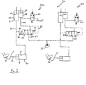
- Figure 3 is a schematic diagram of a braking system in accordance with a first embodiment of the invention
- Figure 4 is a schematic diagram of a braking system in accordance with a second embodiment of the invention.
- a tractor 10 comprises a driver's cab 2, a bonnet 3, front axle 14 and rear axle 15.
- a pair of steerable wheels 16 are mounted on respective ends of the front axle 14.
- Hydraulically actuated steering rods 17 are mounted from the tractor chassis to the steerable wheels 16 which cause the wheels 16 to pivot in unison around respective vertical axes 8 through a range of steering angles.
- Figure 2 shows the steerable wheels in a straight ahead direction as well as a direction pivoted to the right (shown by the dashed line).
- the tractor further comprises a pair of rear braked wheels 12L and 12R mounted on respective ends of the rear axle 15.
- Each of the rear braked wheels 12L, 12R have associated therewith braking means which serve to brake the associated wheel.
- the tractor shown in Figure 1 merely provides an example vehicle upon which a braking system in accordance with the invention can be implemented. Two example embodiments of the invention will now be described in relation to the tractor of Figure 1 .
- the tractor 10 is a wheeled vehicle having at least one braked wheel 12 and a hydraulic reservoir 26, represented by a pump symbol in figures 1 , 3 and 4 , having an operating pressure.
- a brake system 30 in accordance with a first embodiment of the invention is fitted to the tractor 10 which comprises two braked wheels 12L, 12R.
- Each braked wheel has an associated dedicated braking circuit and pedal.
- a first pedal 32 serves to operate the brake on a left-hand (rear) wheel t2L and a second pedal 32' serves to operate the brake on a right-hand (rear) wheel 12R.
- the pedals 32,32' are positioned adjacent one another in the cab to allow the driver to operate the pedals simultaneously with one foot.
- the driver may operate the pedals 32,32' individually to aid turning of the tractor, for example in wet and muddy conditions.
- the pedals can be optionally locked together with a locking bar (not shown).
- the system 30 comprises a left-hand brake circuit 30L for operation of the left-hand brake and a right-hand brake circuit 30R for operation of the right-hand brake. It should be appreciated that the following description of the left-hand brake circuit 30L will also apply to the identical right-hand brake circuit 30R.
- the circuit 30L comprises a master cylinder 20 and a piston 18 located and moveable therein.
- the piston 18 is actuated by movement of the left-hand pedal 32L which is depressed by the driver's foot and connected to the piston 18 by a piston rod 19. Movement of the piston 18 displaces fluid in a chamber 21 and causes the resultant hydraulic pressure to be delivered to a first slave cylinder 48 via a hydraulic connection 23.
- the first slave cylinder 48 comprises a piston 49 which is moved as a result of hydraulic pressure in the first slave cylinder chamber 51. It will be appreciated that movement of the piston 49 actuates the brakes (not shown) connected thereto which includes brake pads which exert a force on a brake disc associated with the left-hand rear wheel 12L of the tractor 10.
- the hydraulic connection 23 provides a first mechanism for activation of the left-hand brake by depression of the left-hand brake pedal 32L.
- the circuit 30L further comprises a directional control 'boost' valve 24 which provides a second mechanism to activate the left-hand brake in response to depression of the left-hand brake pedal 32L.
- the boost valve 24 comprises three ports and is operable between two positions.
- a spring 25 biases the valve into a first position (shown in Figure 3 ) wherein a tank line 27, having a relatively low hydraulic pressure, is connected to a second slave cylinder 58 via a boost connection 43.
- a pilot pressure is delivered from the hydraulic connection 23 to the valve 24 by a hydraulic pilot connection 45 to force the valve 24 into a second position.
- a second pilot line 47 is connected between the boost connection 43 and the valve 24 to provide a reactant pressure to that provided by the pilot connection 45. This ensures that the pressure in boost connection 43 is dependent upon the pressure in pilot line 45.
- valve 24 connects the transmission 26 of the tractor to the boost connection 43. In this way the operating pressure of the transmission 26 is delivered to the second slave cylinder 58 resulting in movement of the piston 59 located therein and activation of the left-hand brake.
- the transmission 26 serves to provide the operating pressure to both the left-hand circuit 30L and the right-hand circuit 30R.
- the provision of two slave cylinders 48,58 to operate a common brake mechanism allows the ratio of forces applied by the direct pedal mechanism and the boost circuit to be adjusted.
- the ratio of the force applied by the second slave cylinder 58 to the force applied by the first slave cylinder 48 is 4:1.
- this ratio can be adjusted by changing the sizing of the respective pistons 49,59 and/or the ends of the boost valve spool connected respectively to pilot lines 45, 47.
- the valve 24 and boost connection 43 provide the second mechanism for activation of the brakes in response to depression of the brake pedal 32.
- the relatively high operating pressure of the vehicle transmission is exploited to provide a braking force deliverable to the second slave cylinder 58.
- the operating pressure is employed in a boost circuit to supplement the pressure conveyed directly from the pedal 32 to the first slave cylinder 48 via the connection 23.
- a backup mechanism is provided wherein the brakes can still be applied by the driver even in the event of failure of the valve 24.
- failure of either of the two mechanisms does not ultimately prevent the driver from applying the brakes by activation of the pedal.
- the boost connection 43 failing by way of a puncture in the pipe, the first slave cylinder can still be actuated.
- the boost valve 24 further comprises an electrically operated solenoid 35 which actuates the boost valve to transmit at least a portion of the operating pressure to the second slave cylinder 58 in response to an electrical signal.
- the solenoid 35 provides a hill-hold function in which the brakes are activated in response to an electronic signal to prevent the tractor from rolling down an incline.
- the solenoid may be activated by a brake control system (not shown) when the transmission is in neutral or when the tractor is stationary with the drive clutch disengaged.
- the hill-hold function may automatically activate the brakes during a change of gear, particularly a change of direction.
- the solenoid-activated brake can be employed to automatically reduce the speed of the tractor before the direction change is made within the transmission.
- a transmission control system may request a reduction in speed.
- the brake control system activates the solenoid for a sufficient duration of time to brake the speed down to a desired level, less than 10kph for example.
- the transmission control system executes the direction/ratio change.
- the circuit 30L further comprises an antilock brake mechanism which includes a solenoid-activated dump valve 60 which connects the boost connection 43 to a dump reservoir 67 in response to an electronic signal sent thereto. This operates automatically in response to the detection of a locked wheel caused by a heavy brake application for example.
- the antilock brake function affects only the second slave cylinder 58, thus not affecting the braking force applied directly by depression of the pedal 32. Furthermore, in the event of failure of dump valve 60, a braking force can still be applied to the wheel via connection 23 and slave cylinder 48.
- the solenoid-activated dump valve 60 can be integrated into the boost valve 24.
- the boost valve 24 is simply provided with an additional solenoid to force the valve into the first (non-braking) position. Therefore, in the event of a locked wheel being detected, the additional solenoid releases the boost braking force by controlling of the boost valve 24.
- FIG. 4 A second embodiment of the invention is shown in Figure 4 . Again, the braking system 40 will be described with reference to the left hand circuit 40L but it should be appreciated that the same components are included in the right hand circuit 40R.
- a single pedal 32 (common to both circuits 40L,40R) is depressed by driver's foot 33 and displaces fluid in the master cylinder chamber 21 which is communicated to a first slave cylinder 48L by hydraulic connection 23.
- the displaced fluid is fed into the chamber 51 of first slave cylinder 48L thereby causing movement of the piston 49 which applies a force to the brakes of braked wheel 19L.
- the braking system 40L also comprises a boost valve 24L which serves to selectively communicate the operating pressure from the transmission to the slave cylinder apparatus by actuation thereof.
- the operating pressure acts on a piston 59 in the second slave cylinder 58L by means of hydraulic connection 43.
- the boost valves 24L, 24R are actuated by one of two mechanisms, a) application of a pilot hydraulic pressure from pilot line 45 or b) by actuation of solenoid 35.
- Sensing means 180 mounted on the front axle 14 serve to measure the steering angle of the steerable wheels 16. For the purpose of describing this arrangement a steering angle of 0° will equate to a straight ahead direction whereas a steering angle of 100% will equate to full left hand lock or full right hand lock.
- the steering angle sensed by sensing means 180 is communicated to the control unit 190.
- the control unit 190 communicates electrical signals to the respective solenoids 35 to automatically activate one of the boost valves 24L, 24R.
- the control means activates solenoid 35 so as to cause automatic application of the left hand brake. This serves to assist the steering of the tractor to the left hand side.
- the signal sent by the control unit 190 to the solenoid 35 is discontinued allowing the spring 25 to return the valve to the first position thus removing the braking force.
- control means 190 sends a signal to the other solenoid so as to cause application of the right hand brake thus assisting steering of the tractor to the right.
- control unit 190 is also supplied with data regarding the speed of the vehicle. In the event that the vehicle speed exceeds 2kph then automatic operation of the brakes by activation of the respective solenoids 35 will not occur irrespective of the steering angle sensed.
- control unit 190 Automatic operation of the brakes by control unit 190 can be selectively activated and deactivated by the driver using a simple toggle switch located in the cab (not shown).
- the parameters which determine when the control unit 190 activates the solenoids 35 given in the above description can be varied.
- automatic activation of the left hand wheel may only occur when the steering angle exceeds 95% to the left.
- the automatic activation of the brakes by control unit 190 maybe prohibited at ground speeds above 1 kph.
- the predetermined period at which the steering angle exceeds the threshold may be 2 seconds or even as much as 5 seconds. Any of these parameters may or may not be adjustable by the driver located in the cab 2.
- Figure 4 comprises a single brake pedal 32 for activation of both left hand and right hand brakes it is envisaged that the more traditional brake pedal arrangement can be employed without deviating from the scope of the invention.
- a first brake pedal is depressed to activate the left hand brake and a second pedal is depressed to activate the right hand brake as per the embodiment of Figure 3 .
- a single pedal could replace the two pedals 32,32' in Figure 3 , with a common hydraulic connection to both of the first slave cylinders 48.
- a tractor comprising a braking system and a dual slave cylinder arrangement.
- a pedal-operated master cylinder is connected directly to a first slave cylinder by a hydraulic connection.
- An auxiliary hydraulic reservoir having an operating pressure is selectively connected to a second slave cylinder via a boost valve in response to a pilot pressure communicated from the hydraulic connection.
Landscapes
- Engineering & Computer Science (AREA)
- Transportation (AREA)
- Mechanical Engineering (AREA)
- Chemical & Material Sciences (AREA)
- Combustion & Propulsion (AREA)
- Physics & Mathematics (AREA)
- Fluid Mechanics (AREA)
- Regulating Braking Force (AREA)
- Braking Elements And Transmission Devices (AREA)
Claims (12)
- Tracteur (10) avec un dispositif de transmission et un dispositif de freinage (30 ; 40) comprenant un maître-cylindre commandé par pédale (20) relié à un premier cylindre récepteur (48) par une liaison hydraulique (23), et une vanne auxiliaire (24) destinée à transmettre au moins une partie d'une pression de service à un second cylindre récepteur (58) en réponse à une pression pilote communiquée à partir de la liaison hydraulique (23), les premier et second cylindres récepteurs (48 ; 58) étant agencés de manière à freiner la même roue, dans lequel le dispositif de transmission comprend un réservoir hydraulique auxiliaire (26) qui assure la pression de service.
- Tracteur selon la revendication 1 précédente, dans lequel la vanne auxiliaire (24) comprend un solénoïde (35) qui active la vanne auxiliaire (24) afin de transmettre au moins une partie de la pression de service au second cylindre récepteur en réponse à un signal électronique.
- Tracteur selon la revendication 1 ou 2, comprenant une roue gauche freinée (12L) et une roue droite freinée (12R), chacune comportant un dispositif de freinage présentant la construction décrite et une pédale de frein respective (32, 32') associée à ce dernier.
- Tracteur selon la revendication 1 ou 2, comprenant une paire de roues directrices (16) qui pivotent chacune à l'unisson autour d'axes verticaux respectifs (8) sur une plage d'angles de braquage, des moyens de détection (80) afin de détecter l'angle de braquage, et une roue freinée (12L, 12R) sur chacun des côtés gauche et droit du tracteur, chaque roue freinée étant associée à un dispositif de freinage présentant la construction décrite qui freine la roue associée de manière automatique en réponse à un signal électrique à partir du moyen de détection, le signal étant envoyé au solénoïde associé lorsque l'angle de braquage dans la direction correspondant au côté de la roue freinée associée dépasse un seuil de manière à assister la direction du tracteur.
- Tracteur selon la revendication 4, dans lequel le seuil est supérieur à 90% de la plage de braquage par rapport à une direction rectiligne vers l'avant jusqu'à la limite de braquage.
- Tracteur selon la revendication 4 ou 5, dans lequel le dispositif de freinage freine la roue freinée associée de manière automatique uniquement lorsque la vitesse au sol de véhicule est inférieure à un seuil prédéterminé.
- Tracteur selon l'une quelconque des revendications 4 à 6, dans lequel un opérateur peut activer de manière sélective un mode automatique qui assure le fonctionnement automatique du dispositif de freinage.
- Tracteur selon l'une quelconque des revendications 4 à 7, dans lequel le dispositif de freinage freine uniquement la roue freinée associée de manière automatique lorsque l'angle de braquage dans la direction correspondant au côté de la roue freinée associée excède ledit seuil pendant une période prédéterminée.
- Tracteur selon l'une quelconque des revendications 4 à 8, dans lequel les moyens de détection détectent l'angle de braquage en mesurant la position angulaire d'un axe vertical sur lequel l'une des roues directrices est montée.
- Tracteur selon l'une quelconque des revendications 4 à 9, dans lequel chaque dispositif de freinage freine la roue associée respective en réponse à la commande d'une pédale de freinage unique qui est commune aux deux roues freinées.
- Tracteur selon la revendication 2, dans lequel le solénoïde est activé de manière automatique lorsqu'une transmission est à un rapport de transmission neutre et lorsque le tracteur est sur un plan incliné de manière à empêcher le déplacement en roue libre du tracteur.
- Tracteur comprenant un dispositif de freinage selon l'une quelconque des revendications 1 ou 2, dans lequel une vanne antipatinage (60) est agencée de manière à réduire la pression de service du deuxième cylindre récepteur en réponse à la détection d'un blocage de roue.
Applications Claiming Priority (2)
| Application Number | Priority Date | Filing Date | Title |
|---|---|---|---|
| GB0817048A GB2463648A (en) | 2008-09-18 | 2008-09-18 | Braking system having a dual slave cylinder arrangement |
| PCT/EP2009/061708 WO2010031722A1 (fr) | 2008-09-18 | 2009-09-09 | Système de freinage |
Publications (2)
| Publication Number | Publication Date |
|---|---|
| EP2337721A1 EP2337721A1 (fr) | 2011-06-29 |
| EP2337721B1 true EP2337721B1 (fr) | 2014-11-19 |
Family
ID=39930345
Family Applications (1)
| Application Number | Title | Priority Date | Filing Date |
|---|---|---|---|
| EP09782833.9A Active EP2337721B1 (fr) | 2008-09-18 | 2009-09-09 | Tracteur agricole |
Country Status (3)
| Country | Link |
|---|---|
| EP (1) | EP2337721B1 (fr) |
| GB (1) | GB2463648A (fr) |
| WO (1) | WO2010031722A1 (fr) |
Cited By (1)
| Publication number | Priority date | Publication date | Assignee | Title |
|---|---|---|---|---|
| CN106114621A (zh) * | 2015-05-08 | 2016-11-16 | 克拉斯工业技术有限责任公司 | 农业作业机械 |
Families Citing this family (7)
| Publication number | Priority date | Publication date | Assignee | Title |
|---|---|---|---|---|
| CN103950389B (zh) * | 2014-01-20 | 2016-02-10 | 南京工程学院 | 电动汽车液控泵/马达助力系统 |
| US9873415B2 (en) | 2016-02-23 | 2018-01-23 | Cnh Industrial America Llc | System for providing speed-dependent control of a brake of a hauled unit of a work vehicle and related valve assembly |
| GB201720471D0 (en) | 2017-12-08 | 2018-01-24 | Agco Int Gmbh | Utility vehicle braking |
| CN110116719B (zh) * | 2019-05-29 | 2023-12-22 | 四川川龙拖拉机制造有限公司 | 一种拖拉机制动系统及拖拉机 |
| IT202000012421A1 (it) * | 2020-05-26 | 2021-11-26 | Cnh Ind Italia Spa | Disposizione idraulica migliorata di controllo di un servofreno per veicoli da lavoro |
| DE102020119750A1 (de) * | 2020-07-27 | 2022-01-27 | Deere & Company | Fahrzeugbremsanlage und landwirtschaftliches Zugfahrzeug |
| IT202200007202A1 (it) * | 2022-04-12 | 2023-10-12 | Carraro Antonio Spa | Dispositivo di frenata sterzante per veicoli da lavoro |
Family Cites Families (10)
| Publication number | Priority date | Publication date | Assignee | Title |
|---|---|---|---|---|
| GB795874A (en) * | 1955-05-11 | 1958-06-04 | Girling Ltd | A new or improved control for hydraulic servo mechanism |
| FR1267491A (fr) | 1960-09-13 | 1961-07-21 | Schlepperwerk Nordhausen Veb | Dispositif permettant de freiner individuellement ou simultanément les roues d'un véhicule notamment pour tracteurs |
| GB1169553A (en) * | 1966-07-14 | 1969-11-05 | Girling Ltd | Improvements in or relating to Hydraulic Brake Systems |
| GB1318886A (en) * | 1969-09-16 | 1973-05-31 | Girling Ltd | Hydraulic actuating systems |
| GB1267649A (en) * | 1970-07-21 | 1972-03-22 | Ifa Getriebewerke Brandenburg | Improvements in or relating to a vehicle provided with a brake slewing system |
| FR2701910B3 (fr) * | 1993-02-24 | 1995-01-20 | Yang Hsiao Rui | Système de freins hydrauliques à deux maitres-cylindres. |
| JPH07117644A (ja) * | 1993-10-25 | 1995-05-09 | Sumitomo Electric Ind Ltd | 車輌のブレーキシステム |
| EP0761519B1 (fr) | 1995-09-12 | 2001-12-12 | FTE automotive GmbH | Système de freinage hydraulique pour véhicules |
| FR2761742B1 (fr) * | 1997-04-03 | 1999-05-07 | Bosch Syst Freinage | Systeme de freinage a absorption reduite |
| DE10029819C1 (de) | 2000-06-16 | 2002-05-23 | Daimler Chrysler Ag | Fahrzeug |
-
2008
- 2008-09-18 GB GB0817048A patent/GB2463648A/en not_active Withdrawn
-
2009
- 2009-09-09 EP EP09782833.9A patent/EP2337721B1/fr active Active
- 2009-09-09 WO PCT/EP2009/061708 patent/WO2010031722A1/fr active Application Filing
Cited By (1)
| Publication number | Priority date | Publication date | Assignee | Title |
|---|---|---|---|---|
| CN106114621A (zh) * | 2015-05-08 | 2016-11-16 | 克拉斯工业技术有限责任公司 | 农业作业机械 |
Also Published As
| Publication number | Publication date |
|---|---|
| EP2337721A1 (fr) | 2011-06-29 |
| WO2010031722A1 (fr) | 2010-03-25 |
| GB2463648A (en) | 2010-03-24 |
| GB0817048D0 (en) | 2008-10-22 |
Similar Documents
| Publication | Publication Date | Title |
|---|---|---|
| EP2337721B1 (fr) | Tracteur agricole | |
| EP1185448B1 (fr) | Freinage de secours dans un systeme de freinage electrohydraulique (ehb) | |
| US8616659B2 (en) | Vehicle steering and braking system | |
| EP2093112B1 (fr) | Appareil de freinage à contrôle électronique pour tracteurs | |
| JP5390615B2 (ja) | 作業機械のブレーキ・システムを作動するための方法および作業機械のためのブレーキ・システム | |
| US20080257679A1 (en) | Motor vehicle equipped with an integrated brake and clutch control system | |
| JP6797634B2 (ja) | ブレーキシステム | |
| EP1982897B1 (fr) | Procédé de commande de véhicule | |
| EP3265349B1 (fr) | Système de freinage | |
| JP3907464B2 (ja) | トラクタ | |
| EP2894069B1 (fr) | Agencement de direction et de freinage | |
| US9469285B2 (en) | Brake arrangement | |
| EA035918B1 (ru) | Тормозная система автомобиля и способ управления тормозной системой | |
| GB2462839A (en) | Tractor braking system having left and right hand brake circuits | |
| US20200172070A1 (en) | Electrohydraulic brake system for an off-road vehicle | |
| US20240092329A1 (en) | Trailer Brake Control System | |
| US20240001900A1 (en) | Trailer Brake Control System | |
| JP3731282B2 (ja) | 作業車両の操向制御装置 | |
| EP3397535B1 (fr) | Systeme de freinage pour vehicule agricole avec fonctions de securite et auxiliaires, et methode de controle du systeme | |
| EP3180214B1 (fr) | Système de commande de freinage hydraulique pour véhicules agricoles ou similaires et procédé de fabrication associé | |
| EP0257976A2 (fr) | Maître-cylindre | |
| JPH01215678A (ja) | ブレーキ装置 |
Legal Events
| Date | Code | Title | Description |
|---|---|---|---|
| PUAI | Public reference made under article 153(3) epc to a published international application that has entered the european phase |
Free format text: ORIGINAL CODE: 0009012 |
|
| 17P | Request for examination filed |
Effective date: 20110418 |
|
| AK | Designated contracting states |
Kind code of ref document: A1 Designated state(s): AT BE BG CH CY CZ DE DK EE ES FI FR GB GR HR HU IE IS IT LI LT LU LV MC MK MT NL NO PL PT RO SE SI SK SM TR |
|
| AX | Request for extension of the european patent |
Extension state: AL BA RS |
|
| DAX | Request for extension of the european patent (deleted) | ||
| REG | Reference to a national code |
Ref country code: DE Ref legal event code: R079 Ref document number: 602009027874 Country of ref document: DE Free format text: PREVIOUS MAIN CLASS: B60T0017100000 Ipc: B62D0049000000 |
|
| GRAP | Despatch of communication of intention to grant a patent |
Free format text: ORIGINAL CODE: EPIDOSNIGR1 |
|
| RIC1 | Information provided on ipc code assigned before grant |
Ipc: B62D 49/00 20060101AFI20140522BHEP |
|
| INTG | Intention to grant announced |
Effective date: 20140624 |
|
| GRAS | Grant fee paid |
Free format text: ORIGINAL CODE: EPIDOSNIGR3 |
|
| GRAA | (expected) grant |
Free format text: ORIGINAL CODE: 0009210 |
|
| AK | Designated contracting states |
Kind code of ref document: B1 Designated state(s): AT BE BG CH CY CZ DE DK EE ES FI FR GB GR HR HU IE IS IT LI LT LU LV MC MK MT NL NO PL PT RO SE SI SK SM TR |
|
| REG | Reference to a national code |
Ref country code: GB Ref legal event code: FG4D |
|
| REG | Reference to a national code |
Ref country code: CH Ref legal event code: EP |
|
| REG | Reference to a national code |
Ref country code: AT Ref legal event code: REF Ref document number: 696823 Country of ref document: AT Kind code of ref document: T Effective date: 20141215 |
|
| REG | Reference to a national code |
Ref country code: IE Ref legal event code: FG4D |
|
| REG | Reference to a national code |
Ref country code: DE Ref legal event code: R096 Ref document number: 602009027874 Country of ref document: DE Effective date: 20141231 |
|
| REG | Reference to a national code |
Ref country code: NL Ref legal event code: VDEP Effective date: 20141119 |
|
| REG | Reference to a national code |
Ref country code: AT Ref legal event code: MK05 Ref document number: 696823 Country of ref document: AT Kind code of ref document: T Effective date: 20141119 |
|
| REG | Reference to a national code |
Ref country code: LT Ref legal event code: MG4D |
|
| PG25 | Lapsed in a contracting state [announced via postgrant information from national office to epo] |
Ref country code: FI Free format text: LAPSE BECAUSE OF FAILURE TO SUBMIT A TRANSLATION OF THE DESCRIPTION OR TO PAY THE FEE WITHIN THE PRESCRIBED TIME-LIMIT Effective date: 20141119 Ref country code: IS Free format text: LAPSE BECAUSE OF FAILURE TO SUBMIT A TRANSLATION OF THE DESCRIPTION OR TO PAY THE FEE WITHIN THE PRESCRIBED TIME-LIMIT Effective date: 20150319 Ref country code: PT Free format text: LAPSE BECAUSE OF FAILURE TO SUBMIT A TRANSLATION OF THE DESCRIPTION OR TO PAY THE FEE WITHIN THE PRESCRIBED TIME-LIMIT Effective date: 20150319 Ref country code: NO Free format text: LAPSE BECAUSE OF FAILURE TO SUBMIT A TRANSLATION OF THE DESCRIPTION OR TO PAY THE FEE WITHIN THE PRESCRIBED TIME-LIMIT Effective date: 20150219 Ref country code: ES Free format text: LAPSE BECAUSE OF FAILURE TO SUBMIT A TRANSLATION OF THE DESCRIPTION OR TO PAY THE FEE WITHIN THE PRESCRIBED TIME-LIMIT Effective date: 20141119 Ref country code: NL Free format text: LAPSE BECAUSE OF FAILURE TO SUBMIT A TRANSLATION OF THE DESCRIPTION OR TO PAY THE FEE WITHIN THE PRESCRIBED TIME-LIMIT Effective date: 20141119 Ref country code: LT Free format text: LAPSE BECAUSE OF FAILURE TO SUBMIT A TRANSLATION OF THE DESCRIPTION OR TO PAY THE FEE WITHIN THE PRESCRIBED TIME-LIMIT Effective date: 20141119 |
|
| PG25 | Lapsed in a contracting state [announced via postgrant information from national office to epo] |
Ref country code: SE Free format text: LAPSE BECAUSE OF FAILURE TO SUBMIT A TRANSLATION OF THE DESCRIPTION OR TO PAY THE FEE WITHIN THE PRESCRIBED TIME-LIMIT Effective date: 20141119 Ref country code: GR Free format text: LAPSE BECAUSE OF FAILURE TO SUBMIT A TRANSLATION OF THE DESCRIPTION OR TO PAY THE FEE WITHIN THE PRESCRIBED TIME-LIMIT Effective date: 20150220 Ref country code: LV Free format text: LAPSE BECAUSE OF FAILURE TO SUBMIT A TRANSLATION OF THE DESCRIPTION OR TO PAY THE FEE WITHIN THE PRESCRIBED TIME-LIMIT Effective date: 20141119 Ref country code: CY Free format text: LAPSE BECAUSE OF FAILURE TO SUBMIT A TRANSLATION OF THE DESCRIPTION OR TO PAY THE FEE WITHIN THE PRESCRIBED TIME-LIMIT Effective date: 20141119 Ref country code: PL Free format text: LAPSE BECAUSE OF FAILURE TO SUBMIT A TRANSLATION OF THE DESCRIPTION OR TO PAY THE FEE WITHIN THE PRESCRIBED TIME-LIMIT Effective date: 20141119 Ref country code: HR Free format text: LAPSE BECAUSE OF FAILURE TO SUBMIT A TRANSLATION OF THE DESCRIPTION OR TO PAY THE FEE WITHIN THE PRESCRIBED TIME-LIMIT Effective date: 20141119 Ref country code: AT Free format text: LAPSE BECAUSE OF FAILURE TO SUBMIT A TRANSLATION OF THE DESCRIPTION OR TO PAY THE FEE WITHIN THE PRESCRIBED TIME-LIMIT Effective date: 20141119 |
|
| PG25 | Lapsed in a contracting state [announced via postgrant information from national office to epo] |
Ref country code: RO Free format text: LAPSE BECAUSE OF FAILURE TO SUBMIT A TRANSLATION OF THE DESCRIPTION OR TO PAY THE FEE WITHIN THE PRESCRIBED TIME-LIMIT Effective date: 20141119 Ref country code: DK Free format text: LAPSE BECAUSE OF FAILURE TO SUBMIT A TRANSLATION OF THE DESCRIPTION OR TO PAY THE FEE WITHIN THE PRESCRIBED TIME-LIMIT Effective date: 20141119 Ref country code: EE Free format text: LAPSE BECAUSE OF FAILURE TO SUBMIT A TRANSLATION OF THE DESCRIPTION OR TO PAY THE FEE WITHIN THE PRESCRIBED TIME-LIMIT Effective date: 20141119 Ref country code: SK Free format text: LAPSE BECAUSE OF FAILURE TO SUBMIT A TRANSLATION OF THE DESCRIPTION OR TO PAY THE FEE WITHIN THE PRESCRIBED TIME-LIMIT Effective date: 20141119 Ref country code: CZ Free format text: LAPSE BECAUSE OF FAILURE TO SUBMIT A TRANSLATION OF THE DESCRIPTION OR TO PAY THE FEE WITHIN THE PRESCRIBED TIME-LIMIT Effective date: 20141119 |
|
| REG | Reference to a national code |
Ref country code: DE Ref legal event code: R097 Ref document number: 602009027874 Country of ref document: DE |
|
| PLBE | No opposition filed within time limit |
Free format text: ORIGINAL CODE: 0009261 |
|
| STAA | Information on the status of an ep patent application or granted ep patent |
Free format text: STATUS: NO OPPOSITION FILED WITHIN TIME LIMIT |
|
| 26N | No opposition filed |
Effective date: 20150820 |
|
| PG25 | Lapsed in a contracting state [announced via postgrant information from national office to epo] |
Ref country code: SI Free format text: LAPSE BECAUSE OF FAILURE TO SUBMIT A TRANSLATION OF THE DESCRIPTION OR TO PAY THE FEE WITHIN THE PRESCRIBED TIME-LIMIT Effective date: 20141119 |
|
| PG25 | Lapsed in a contracting state [announced via postgrant information from national office to epo] |
Ref country code: MC Free format text: LAPSE BECAUSE OF FAILURE TO SUBMIT A TRANSLATION OF THE DESCRIPTION OR TO PAY THE FEE WITHIN THE PRESCRIBED TIME-LIMIT Effective date: 20141119 Ref country code: LU Free format text: LAPSE BECAUSE OF FAILURE TO SUBMIT A TRANSLATION OF THE DESCRIPTION OR TO PAY THE FEE WITHIN THE PRESCRIBED TIME-LIMIT Effective date: 20150909 |
|
| REG | Reference to a national code |
Ref country code: CH Ref legal event code: PL |
|
| REG | Reference to a national code |
Ref country code: IE Ref legal event code: MM4A |
|
| PG25 | Lapsed in a contracting state [announced via postgrant information from national office to epo] |
Ref country code: CH Free format text: LAPSE BECAUSE OF NON-PAYMENT OF DUE FEES Effective date: 20150930 Ref country code: IE Free format text: LAPSE BECAUSE OF NON-PAYMENT OF DUE FEES Effective date: 20150909 Ref country code: LI Free format text: LAPSE BECAUSE OF NON-PAYMENT OF DUE FEES Effective date: 20150930 |
|
| REG | Reference to a national code |
Ref country code: FR Ref legal event code: PLFP Year of fee payment: 8 |
|
| PG25 | Lapsed in a contracting state [announced via postgrant information from national office to epo] |
Ref country code: MT Free format text: LAPSE BECAUSE OF FAILURE TO SUBMIT A TRANSLATION OF THE DESCRIPTION OR TO PAY THE FEE WITHIN THE PRESCRIBED TIME-LIMIT Effective date: 20141119 |
|
| PG25 | Lapsed in a contracting state [announced via postgrant information from national office to epo] |
Ref country code: HU Free format text: LAPSE BECAUSE OF FAILURE TO SUBMIT A TRANSLATION OF THE DESCRIPTION OR TO PAY THE FEE WITHIN THE PRESCRIBED TIME-LIMIT; INVALID AB INITIO Effective date: 20090909 Ref country code: SM Free format text: LAPSE BECAUSE OF FAILURE TO SUBMIT A TRANSLATION OF THE DESCRIPTION OR TO PAY THE FEE WITHIN THE PRESCRIBED TIME-LIMIT Effective date: 20141119 Ref country code: BG Free format text: LAPSE BECAUSE OF FAILURE TO SUBMIT A TRANSLATION OF THE DESCRIPTION OR TO PAY THE FEE WITHIN THE PRESCRIBED TIME-LIMIT Effective date: 20141119 |
|
| PG25 | Lapsed in a contracting state [announced via postgrant information from national office to epo] |
Ref country code: TR Free format text: LAPSE BECAUSE OF FAILURE TO SUBMIT A TRANSLATION OF THE DESCRIPTION OR TO PAY THE FEE WITHIN THE PRESCRIBED TIME-LIMIT Effective date: 20141119 |
|
| REG | Reference to a national code |
Ref country code: FR Ref legal event code: PLFP Year of fee payment: 9 |
|
| PG25 | Lapsed in a contracting state [announced via postgrant information from national office to epo] |
Ref country code: BE Free format text: LAPSE BECAUSE OF FAILURE TO SUBMIT A TRANSLATION OF THE DESCRIPTION OR TO PAY THE FEE WITHIN THE PRESCRIBED TIME-LIMIT Effective date: 20141119 |
|
| PG25 | Lapsed in a contracting state [announced via postgrant information from national office to epo] |
Ref country code: MK Free format text: LAPSE BECAUSE OF FAILURE TO SUBMIT A TRANSLATION OF THE DESCRIPTION OR TO PAY THE FEE WITHIN THE PRESCRIBED TIME-LIMIT Effective date: 20141119 |
|
| REG | Reference to a national code |
Ref country code: FR Ref legal event code: PLFP Year of fee payment: 10 |
|
| PGFP | Annual fee paid to national office [announced via postgrant information from national office to epo] |
Ref country code: GB Payment date: 20220920 Year of fee payment: 14 Ref country code: DE Payment date: 20220620 Year of fee payment: 14 |
|
| PGFP | Annual fee paid to national office [announced via postgrant information from national office to epo] |
Ref country code: FR Payment date: 20220922 Year of fee payment: 14 |
|
| PGFP | Annual fee paid to national office [announced via postgrant information from national office to epo] |
Ref country code: IT Payment date: 20220921 Year of fee payment: 14 |
|
| P01 | Opt-out of the competence of the unified patent court (upc) registered |
Effective date: 20230518 |
|
| REG | Reference to a national code |
Ref country code: DE Ref legal event code: R119 Ref document number: 602009027874 Country of ref document: DE |
|
| GBPC | Gb: european patent ceased through non-payment of renewal fee |
Effective date: 20230909 |
|
| PG25 | Lapsed in a contracting state [announced via postgrant information from national office to epo] |
Ref country code: GB Free format text: LAPSE BECAUSE OF NON-PAYMENT OF DUE FEES Effective date: 20230909 |
|
| PG25 | Lapsed in a contracting state [announced via postgrant information from national office to epo] |
Ref country code: GB Free format text: LAPSE BECAUSE OF NON-PAYMENT OF DUE FEES Effective date: 20230909 Ref country code: FR Free format text: LAPSE BECAUSE OF NON-PAYMENT OF DUE FEES Effective date: 20230930 Ref country code: DE Free format text: LAPSE BECAUSE OF NON-PAYMENT OF DUE FEES Effective date: 20240403 |