EP3265349B1 - Système de freinage - Google Patents
Système de freinage Download PDFInfo
- Publication number
- EP3265349B1 EP3265349B1 EP16706881.6A EP16706881A EP3265349B1 EP 3265349 B1 EP3265349 B1 EP 3265349B1 EP 16706881 A EP16706881 A EP 16706881A EP 3265349 B1 EP3265349 B1 EP 3265349B1
- Authority
- EP
- European Patent Office
- Prior art keywords
- pressure
- brake
- brake fluid
- master cylinder
- valve
- Prior art date
- Legal status (The legal status is an assumption and is not a legal conclusion. Google has not performed a legal analysis and makes no representation as to the accuracy of the status listed.)
- Active
Links
- 239000012530 fluid Substances 0.000 claims description 156
- 230000009471 action Effects 0.000 claims description 6
- 238000000034 method Methods 0.000 claims description 6
- 238000009434 installation Methods 0.000 claims description 3
- 238000012544 monitoring process Methods 0.000 claims description 2
- 230000004044 response Effects 0.000 description 4
- 230000004913 activation Effects 0.000 description 3
- 238000010276 construction Methods 0.000 description 3
- 230000000717 retained effect Effects 0.000 description 3
- 230000008878 coupling Effects 0.000 description 2
- 238000010168 coupling process Methods 0.000 description 2
- 238000005859 coupling reaction Methods 0.000 description 2
- 230000000694 effects Effects 0.000 description 2
- 230000009118 appropriate response Effects 0.000 description 1
- 238000013016 damping Methods 0.000 description 1
- 230000009977 dual effect Effects 0.000 description 1
- 230000009467 reduction Effects 0.000 description 1
- 230000008439 repair process Effects 0.000 description 1
- 230000004043 responsiveness Effects 0.000 description 1
- 238000009420 retrofitting Methods 0.000 description 1
Images


Classifications
-
- B—PERFORMING OPERATIONS; TRANSPORTING
- B60—VEHICLES IN GENERAL
- B60T—VEHICLE BRAKE CONTROL SYSTEMS OR PARTS THEREOF; BRAKE CONTROL SYSTEMS OR PARTS THEREOF, IN GENERAL; ARRANGEMENT OF BRAKING ELEMENTS ON VEHICLES IN GENERAL; PORTABLE DEVICES FOR PREVENTING UNWANTED MOVEMENT OF VEHICLES; VEHICLE MODIFICATIONS TO FACILITATE COOLING OF BRAKES
- B60T11/00—Transmitting braking action from initiating means to ultimate brake actuator without power assistance or drive or where such assistance or drive is irrelevant
- B60T11/10—Transmitting braking action from initiating means to ultimate brake actuator without power assistance or drive or where such assistance or drive is irrelevant transmitting by fluid means, e.g. hydraulic
- B60T11/101—Transmitting braking action from initiating means to ultimate brake actuator without power assistance or drive or where such assistance or drive is irrelevant transmitting by fluid means, e.g. hydraulic equalising arrangements
-
- B—PERFORMING OPERATIONS; TRANSPORTING
- B60—VEHICLES IN GENERAL
- B60T—VEHICLE BRAKE CONTROL SYSTEMS OR PARTS THEREOF; BRAKE CONTROL SYSTEMS OR PARTS THEREOF, IN GENERAL; ARRANGEMENT OF BRAKING ELEMENTS ON VEHICLES IN GENERAL; PORTABLE DEVICES FOR PREVENTING UNWANTED MOVEMENT OF VEHICLES; VEHICLE MODIFICATIONS TO FACILITATE COOLING OF BRAKES
- B60T11/00—Transmitting braking action from initiating means to ultimate brake actuator without power assistance or drive or where such assistance or drive is irrelevant
- B60T11/10—Transmitting braking action from initiating means to ultimate brake actuator without power assistance or drive or where such assistance or drive is irrelevant transmitting by fluid means, e.g. hydraulic
- B60T11/16—Master control, e.g. master cylinders
- B60T11/20—Tandem, side-by-side, or other multiple master cylinder units
- B60T11/21—Tandem, side-by-side, or other multiple master cylinder units with two pedals operating on respective circuits, pressures therein being equalised when both pedals are operated together, e.g. for steering
-
- B—PERFORMING OPERATIONS; TRANSPORTING
- B60—VEHICLES IN GENERAL
- B60T—VEHICLE BRAKE CONTROL SYSTEMS OR PARTS THEREOF; BRAKE CONTROL SYSTEMS OR PARTS THEREOF, IN GENERAL; ARRANGEMENT OF BRAKING ELEMENTS ON VEHICLES IN GENERAL; PORTABLE DEVICES FOR PREVENTING UNWANTED MOVEMENT OF VEHICLES; VEHICLE MODIFICATIONS TO FACILITATE COOLING OF BRAKES
- B60T13/00—Transmitting braking action from initiating means to ultimate brake actuator with power assistance or drive; Brake systems incorporating such transmitting means, e.g. air-pressure brake systems
- B60T13/10—Transmitting braking action from initiating means to ultimate brake actuator with power assistance or drive; Brake systems incorporating such transmitting means, e.g. air-pressure brake systems with fluid assistance, drive, or release
- B60T13/66—Electrical control in fluid-pressure brake systems
- B60T13/662—Electrical control in fluid-pressure brake systems characterised by specified functions of the control system components
-
- B—PERFORMING OPERATIONS; TRANSPORTING
- B60—VEHICLES IN GENERAL
- B60T—VEHICLE BRAKE CONTROL SYSTEMS OR PARTS THEREOF; BRAKE CONTROL SYSTEMS OR PARTS THEREOF, IN GENERAL; ARRANGEMENT OF BRAKING ELEMENTS ON VEHICLES IN GENERAL; PORTABLE DEVICES FOR PREVENTING UNWANTED MOVEMENT OF VEHICLES; VEHICLE MODIFICATIONS TO FACILITATE COOLING OF BRAKES
- B60T13/00—Transmitting braking action from initiating means to ultimate brake actuator with power assistance or drive; Brake systems incorporating such transmitting means, e.g. air-pressure brake systems
- B60T13/10—Transmitting braking action from initiating means to ultimate brake actuator with power assistance or drive; Brake systems incorporating such transmitting means, e.g. air-pressure brake systems with fluid assistance, drive, or release
- B60T13/66—Electrical control in fluid-pressure brake systems
- B60T13/68—Electrical control in fluid-pressure brake systems by electrically-controlled valves
- B60T13/686—Electrical control in fluid-pressure brake systems by electrically-controlled valves in hydraulic systems or parts thereof
-
- B—PERFORMING OPERATIONS; TRANSPORTING
- B62—LAND VEHICLES FOR TRAVELLING OTHERWISE THAN ON RAILS
- B62D—MOTOR VEHICLES; TRAILERS
- B62D11/00—Steering non-deflectable wheels; Steering endless tracks or the like
- B62D11/02—Steering non-deflectable wheels; Steering endless tracks or the like by differentially driving ground-engaging elements on opposite vehicle sides
- B62D11/06—Steering non-deflectable wheels; Steering endless tracks or the like by differentially driving ground-engaging elements on opposite vehicle sides by means of a single main power source
- B62D11/08—Steering non-deflectable wheels; Steering endless tracks or the like by differentially driving ground-engaging elements on opposite vehicle sides by means of a single main power source using brakes or clutches as main steering-effecting means
Definitions
- the present invention relates to a braking system for a vehicle, in particular a braking system having separate brake pedals for actuation of separate wheel brakes.
- separate brake pedals may be provided for the separate actuation of wheel brakes of the vehicle, for a brake pedal for actuating the brake on the right rear wheel being on the right side of the tractor chassis for engagement by the right foot of the operator, and the brake pedal for operating the brake on the left rear wheel being on the left side of the chassis for operation by the left foot of the operator. While both brakes may be actuated at the same time to stop the vehicle, selective actuation of the separate brakes allows for greater control of the vehicle turning circles.
- each master cylinder forms a hydraulic circuit with a respective slave cylinder arranged to drive the respective left and right wheel brakes.
- each master cylinder forms a hydraulic circuit with a respective slave cylinder arranged to drive the respective left and right wheel brakes.
- the use of such separate hydraulic circuits for the operation of the separate left and right wheel brakes prevents pressure harmonisation between the braking circuits, which can lead to an uneven braking response or brake feel between the left and right brake pedals.
- the prior art braking system shown in GB 2476036 A seeks to boost the brake pressure by use of a central brake fluid supply.
- the master cylinders are used to drive shift valves of the slave cylinders, to control the boosted supply of brake fluid to the slave cylinders. Accordingly, brake responsiveness can be impacted, leading to a dead stroke feeling in the use of the master cylinder pedals, before the activation of the slave cylinders.
- EP 1 366 652 A2 A further prior art braking system is described in European patent application EP 1 366 652 A2 .
- Brake fluid from a brake fluid supply is selectively supplied by a selection valve to the left wheel brake, the right wheel brake, or both the left and right wheel brakes, based on the difference between the first master cylinder pressure and the second master cylinder pressure.
- a braking system for an agricultural vehicle as recited in claim 1 of the attached claims.
- the invention is characterised by the inclusion of a central proportional valve to supply brake fluid from the brake fluid supply to the central selection valve, wherein the operation of the central proportional valve is controlled by the pressure of the first and second master cylinders.
- the central proportional valve is configured such that:
- the braking system provides for a pressure harmonisation between the left and right brakes, which can be based on the operator pressure applied to the associated left and right brake pedals.
- the respective left and right wheel brakes are provided with respective first and second slave cylinders to receive the applied brake fluid, and to convert the applied pressure into a braking force applied to the respective wheel brakes.
- the brake fluid may be from a pressurised or boosted brake fluid supply, to provide for an increased brake pressure and an improved braking response time.
- utilising a pressurised or boosted brake fluid supply to apply braking force means that smaller master cylinders can be used in the braking system.
- a central selection valve allows for a balancing of the pressure between the left and right wheel brakes, based on the level of actuation of the left and right brake pedals.
- the first master cylinder pressure is used to drive a first side of the central selection valve
- the second master cylinder pressure is used to drive an opposed second side of the central selection valve.
- any suitable differential pressure valve may be used, which is operable to route brake fluid to the left and/or right brakes, based on the pressure differential between the master cylinders.
- the central selection valve is configured wherein:
- the central selection valve is provided with at least one biasing spring to bias the central selection valve towards the state where brake fluid is supplied to both the left wheel brake and the right wheel brake.
- the biasing strength of the at least one biasing spring may be selected to return the valve to the at-rest position of supplying brake fluid to both brakes, and/or to provide a suitable damping effect to the operation of the central selection valve.
- a first biasing spring is applied to the first side of the central selection valve, and a second biasing spring is applied to the opposed second side of the central selection valve.
- the system further comprises a brake fluid reservoir or tank, wherein the central selection valve is configured such that:
- the other of the wheel brakes may be allowed to drain to the brake fluid reservoir, ensuring that an adequate level of brake fluid remains in circulation in the braking system, and allowing for further pressure harmonisation.
- the system comprises an external brake fluid supply, preferably a pressurised brake fluid supply from a brake fluid reservoir.
- the brake fluid supply comprises an accumulator.
- the accumulator provides a pressurised supply reserve of brake fluid for use in the system.
- the system is arranged where brake fluid from the brake fluid supply is supplied to the central selection valve when the pressure of the first and second master cylinders is above a threshold value.
- the first master cylinder is fluidly coupled with the left wheel brake, preferably with a first slave cylinder coupled to the left wheel brake
- the second master cylinder is fluidly coupled with the right wheel brake, preferably with a second slave cylinder coupled to the right wheel brake.
- the first master cylinder is fluidly coupled with an auxiliary piston of the first slave cylinder of the left wheel brake
- the second master cylinder is fluidly coupled with an auxiliary piston of the second slave cylinder of the right wheel brake, such that the first and second master cylinders can drive the left and right wheel brakes respectively through actuation of the auxiliary pistons.
- the master cylinders may be also connected to the respective wheel brakes directly, as least a portion of the pressure generated by use of the master cylinders may be used to drive brake cylinders associated with the wheel brakes.
- the master cylinder fluid may be used as an auxiliary brake fluid supply, in addition or as an alternative to the brake fluid from the central brake fluid supply.
- Such an auxiliary brake fluid may be used to apply a relatively small braking force to the respective left and right wheel brakes, for states where the pressure of the first and second master cylinders is less than the threshold value for actuation of the central proportional valve to direct the brake fluid from the brake fluid supply to the wheel brakes, e.g. during gentle braking operations.
- the auxiliary supply from the master cylinders may be used to actuate brake cylinders to brake the vehicle.
- the central proportional valve is configured wherein:
- the master cylinder pressure seen by the central proportional valve will drop.
- the central proportional valve may return from its fully actuated position, due to reduced pressure.
- the valve is preferably configured to have a central non-return state, wherein if the pressure falls below an initial actuation pressure level, but remains above a baseline actuation pressure level, the pressurised brake fluid supplied to the slave cylinders is retained in the cylinders to maintain the braking force applied. If the pressure falls further below the baseline actuation pressure level, indicating that the master cylinders are no longer actuated, the valve is configured to allow the pressurised brake fluid to drain from the slave cylinders.
- the system further comprises a shuttle valve driven by the first master cylinder pressure and the second master cylinder pressure, wherein the central proportional valve is driven by the output of the shuttle valve.
- the higher pressure of the first and second master cylinders can be used to actuate the central proportional valve.
- the output of the shuttle valve is used as the input for a trailer brake system.
- the shuttle valve may be used to indicate that a general braking action is being applied by an operator, it can also be used to supply a trailer brake for a trailer coupled to the vehicle.
- the system further comprises a front brake system, wherein an input to a front brake system is based on a combination of the first master cylinder pressure and the second master cylinder pressure.
- the front brake system When operator pressure is applied to both the brake pedals, and corresponding pressure is generated in both master cylinders, the front brake system is actuated to apply a braking pressure to the front brakes of the vehicle.
- the system comprises a valve arranged to produce an output for a front brake system, when the valve is driven by pressure at both the first master cylinder and the second master cylinder.
- the valve is preferably an "AND gate” valve or dual pressure valve.
- a brake control module for installation in vehicle braking system as recited above and claimed herein, the brake control module comprising:
- the brake control module is preferably provided as a component which can be installed in an agricultural vehicle having relatively standard components, such as master cylinders, wheel brakes, brake fluid reservoirs, etc., to allow for the vehicle to be configured to have a braking system as described above.
- the brake fluid is arranged to be received from an external brake fluid supply, e.g. utilising a brake fluid pump coupled to a reservoir and/or a brake fluid accumulator.
- the brake control module may be provided with further inlets and outlets to allow for the implementation of the different functions and features as described above for the overall braking system, e.g. outlets for connection to a trailer brake and/or a front brake, an inlet/outlet port to allow for supply to and from an accumulator, an outlet to allow for drainage of brake fluid to a brake fluid reservoir, etc.
- the brake control module may be provided with suitable sensor connections for coupling with a vehicle Engine Control System (ECU), for example to monitor brake fluid pressure, to alert on a failure state, etc.
- ECU vehicle Engine Control System
- the brake control module may be installed in parallel to an existing fluid connection, e.g. when as a retrofit solution for a vehicle having an existing brake system.
- the brake control module may be provided with suitable outlet ports coupled to the inlet ports to receive inputs from first and second master cylinders, such that the outlet ports can be used to supply fluid from the first and second master cylinders direct to the left and right wheel brakes.
- an agricultural vehicle preferably an agricultural tractor, having a braking system as described above.
- the brake fluid from a brake fluid supply is a pressurised brake fluid, preferably from an external brake fluid supply and/or a brake fluid accumulator.
- central is indicative only, and is not intended to be limiting regarding the actual location of the associated component.
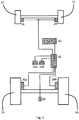
- an agricultural tractor is indicated at 10.
- the tractor 10 comprises front wheels 12, rear wheels 14, an engine section 16 and a cab section 18.
- a steering wheel 20 is provided in the cab 18, along with a pair of brake pedals 22.
- the brake pedals 22 are used to control the braking of the tractor 10, in particular to control the separate braking of the rear wheels 14.
- Fig. 2 provides an overview of the braking system layout for the tractor 10 of Fig. 1 .
- the front wheels 12 of the tractor 10 are provided with linked front wheel brakes 24, while the rear wheels 14 are provided with separate left and right rear wheel brakes 26a,26b.
- the tractor 10 further comprises a trailer brake component 28, which is arranged at the rear of the tractor 10 for connection to the braking system of a linked trailer implement (not shown). While the embodiment of Fig. 2 shows a tractor having a pair of front wheel brakes 24, it will be understood that the invention may also apply to embodiments having a single front wheel brake, to brake both of the front wheels of the tractor.
- the braking system comprises a brake control module 30 which is coupled with the brake pedals 22, the respective front wheel brakes 24 and rear wheel brakes 26a,26b, and the trailer brake component 28.
- the brake control module 30 is further coupled with a supply of brake fluid 32, preferably provided as a pressurised brake fluid supply from an accumulator and/or a pumped brake fluid reservoir.
- the brake pedals 22 are arranged such that a left brake pedal 22a is arranged to control the left rear wheel brake 26a, while a right brake pedal 22b is arranged to control the right rear wheel brake 26b.
- the actuation of the front brakes 24 is linked to the actuation of the left and right pedals 22a,22b together, while the actuation of the trailer brake component 28 is linked to the actuation of the left brake pedal 22a and/or the right brake pedal 22b to a level which requires braking of a connected trailer.
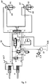
- FIG. 3 A schematic of a braking system according to an embodiment of the invention is illustrated in Fig. 3 .
- the braking system is provided as a hydraulic system.
- the brake pedals 22 shown in Figs. 1 and 2 are coupled to respective hydraulic master cylinders, the left brake pedal 22a acting to drive a first master cylinder A1, and the right brake pedal 22b acting to drive a second master cylinder A2.
- the fluid output of the first master cylinder A1 is provided in hydraulic line PL
- the fluid output of the second master cylinder A2 is provided in hydraulic line PR.
- the separate left and right wheel brakes 26a,26b of Figs. 1 and 2 are driven by respective hydraulic slave cylinders, the left wheel brake 26a driven by a first hydraulic slave cylinder B1, and the right wheel brake 26b driven by a second hydraulic slave cylinder B2.
- the first and second slave cylinders B1,B2 each comprise a primary piston PP and an auxiliary piston AP.
- the primary piston PP of each slave B1,B2 is configured to generate a relatively large breaking force at the respective rear wheel brakes 26a,26b.
- the auxiliary piston AP of each slave B1,B2 is connected to and moves with the respective primary piston PP of the slave.
- the auxiliary piston AP of the first slave cylinder B1 is driven by the hydraulic line L1, and the auxiliary piston PP of the second slave cylinder B2 is driven by the hydraulic line R1.
- the primary piston PP of the first slave cylinder B1 is driven by the hydraulic line L2, and the primary piston PP of the second slave cylinder B2 is driven by the hydraulic line R2.
- the external brake fluid supply 32 of Fig. 2 is provided in the form of a brake fluid tank or reservoir RVR, which is coupled with a supply pump SP, which is arranged to supply a pumped brake fluid supply along hydraulic line P.
- the external brake fluid supply 32 further comprises a brake fluid accumulator ACC, coupled with the pumped supply P via a non-return valve F.
- the use of the supply pump SP combined with the accumulator ACC ensures the provision of a pressurised brake fluid supply for the braking system, but it will be understood that any combination of suitable supply components may be utilised to provide brake fluid supply.
- the system comprises a switch coupled to the pumped brake fluid supply line P, where the switch S is operable to detect a fault in the brake fluid supply.
- the switch S can be arranged to generate a warning signal for a vehicle Engine Control Unit (ECU), and/or to display a warning indicator in a vehicle cabin, displaying a fault in the supply.
- ECU vehicle Engine Control Unit
- the supply pump SP is coupled with a safety or relief valve RF, arranged to provide suitable pressure relief in the brake fluid supply when needed.
- the first and second master cylinders A1,A2 are supplied from a master cylinder tank MCT, to ensure that sufficient hydraulic fluid is provided in the cylinders A1,A2.
- the first master cylinder A1 is connected to hydraulic line PL, and the second master cylinder A2 is connected to hydraulic line PR.
- PL and PR are used as inputs to an "AND gate” valve B, where the output of the "AND gate” valve B is used as the input for a suitable front brake system FB, such as the front brakes 24 shown in Fig. 2 , or a single front wheel brake. Accordingly, when pressure is applied to both the first and second master cylinders A1,A2, which is indicative of an operator actuating both brake pedals 22a,22b, the "AND gate” valve B is actuated, and pressure applied to the front brake system FB to brake the vehicle.
- PL and PR are used as inputs to a shuttle valve C, where the output of the shuttle valve C is used as the input for a suitable trailer brake system TB, such as the trailer brake component 28 shown in Fig. 2 .
- the shuttle valve C acts as an "OR gate", based on the output of the master cylinders A1,A2. Accordingly, when pressure is applied to the first master cylinder A1 and/or to the second master cylinder A2, the shuttle valve C allows for pressure to be supplied to the trailer brake system TB, to generate a braking force for an attached trailer, if present.
- the system further comprises a central proportional valve D, and a central selection valve E. It will be understood that the term “central” is not reflective of a positional limitation of the valves.
- the central proportional valve D is a directional control valve having a valve inlet, a pair of valve outlets, and a central transitory position.
- the valve is biased, preferably spring biased, to an at-rest position wherein the outlets may be drained to the brake fluid reservoir RVR via hydraulic line T.
- the central proportional valve D is actuated by the output of the shuttle valve C, such that an actuation of the first master cylinder A1, or the second master cylinder A2, or both A1 and A2, will result in a corresponding actuation of the central proportional valve D.
- the central proportional valve D is configured to take as input the pressurised brake fluid supply at P and/or the output of the accumulator ACC, and to output the brake fluid to the central selection valve E.
- the central selection valve E is a further directional control valve, having an inlet and a plurality of outlets. Valve E is configured to selectively supply brake fluid from the output of the central proportional valve D to the line L2 to control the primary piston PP of the first slave cylinder B1, or to supply brake fluid to the line R2 to control the primary piston PP of the second slave cylinder B2, or to supply brake fluid to both L2 and R2.
- the central selection valve E is a three-position directional control valve, which is actuated by both the hydraulic line PL at one side of the valve E and the hydraulic line PR at the opposite side of the valve E. Accordingly, the central selection valve E is controlled by the pressure differential between PR and PL, which translates to the difference in pressure between the first master cylinder A1 and the second master cylinder A2.
- the central selection valve E is configured such that:
- the central selection valve E is biased, preferably spring biased, towards a central location wherein an input of valve E from the central proportional valve D is connected to both of the outputs of the valve E, the outputs connected to lines L2 and R2.
- the spring biasing strength of the valves D and E may be selected to provide for appropriate response levels of the braking system.
- the biasing strength of the central proportional valve D may be selected to be a relatively low stiffness, to provide for a relatively fast response time, due to the ease of actuation of the valve D.
- the biasing strength, in combination with the use of central transitory positions of the valves may provide for a hysteresis effect in the actuation of the braking system, which can translate into an improved pedal feeling for an operator.
- braking system of the invention is illustrated in an at-rest state, where no pressure is applied to the brake pedals 22a,22b.
- Figs. 4 and 5 braking system of Fig. 3 is shown for two different operating states.
- both of the brake pedals 22a,22b are actuated. Accordingly, both the first and second master cylinders A1,A2 are also actuated, resulting in a relatively high pressure in both lines PL and PR.
- the "AND gate" valve B is actuated, resulting in an activation of the front brake system FB.
- pressure at both inputs to the shuttle valve C results in an activation of the trailer brake system TB, as well as actuation of the central proportional valve D.
- the central proportional valve D is moved to the state wherein brake fluid from the pressurised brake fluid supply P and/or from the accumulator ACC is supplied to the input of the central selection valve E.
- the valve E As the pressure in PL is greater than the pressure in PR, accordingly the valve E is moved to the position where brake fluid is supplied from the central proportional valve D to only the first slave cylinder B1, via line L2.
- the supplied brake fluid actuates the primary piston PP of the first slave cylinder B1, such that a braking force is applied to the left wheel brake 26a only, e.g. for a vehicle turning operation.
- Fig. 5 illustrates the operation of the braking system during actuation of the left brake pedal 22a only, it will be understood that actuation of the right brake pedal 22b only results in a similar configuration to the schematic of Fig. 5 , but wherein the selection valve E is actuated by the pressure differential between PR and PL to supply brake fluid to the second slave cylinder B2.
- an external pressurised brake fluid supply provides for a fast braking response time.
- the master cylinders may be of reduced volume.
- the external supply e.g. the fluid reservoir, the accumulator, can be located elsewhere in the tractor construction as opposed to in the tractor cabin itself, this allows for a reduction in the cabin space requirements for the braking system.
- the use of a braking system wherein brake fluid supply is controlled based on a pressure differential between different master cylinders results in a pressure harmonisation between the left- and right-side braking systems.
- a safety valve (not shown) may be provided as part of the braking system, the safety valve arranged to connect the lines L2 and R2.
- the safety valve is preferably an ON/OFF valve, which is arranged to fluidly connect lines L2 and R2 in the event of a failure of the braking system, e.g. a failure in selection valve E.
- the safety valve would act to balance the pressures between L2 and R2, and may be activated if a failure in the braking system is detected by a vehicle ECU.
- the safety valve may be controlled as a solenoid valve, having a normally-open operational state.
- the lines PL and PR are respectively connected to lines L1 and R1, such that the first and second master cylinders A1,A2 are fluidly connected with the auxiliary pistons AP of the respective first and second slave cylinders B1,B2.
- this allows for a backup control of the braking system in case of failure of a braking system component, as a limited direct control of the slave cylinders B1,B2 can be achieved by actuation of the respective master cylinders A1,A2, due to the direct connection to the auxiliary pistons AP.
- the auxiliary pistons AP of the slaves are also actuated.
- This generates a draw on the respective lines L1 and/or R1, which leads to a fall in pressure in the respective connected lines PL and/or PR.
- PL and PR are effectively used to control the central proportional valve D, being used as inputs to shuttle valve C, a fall in the pressure of PL and/or PR will result in the central proportional valve D moving back from the fully actuated position, where brake fluid is supplied to selection valve E.
- the biasing of central proportional valve D is configured such that if the master cylinders A1,A2 are released, for example due to pressure no longer being applied to the brake pedals 22a,22b, the central proportional valve D is returned to the at-rest position shown in Fig. 3 . In this position, brake fluid is not supplied to the selection valve E, rather any brake fluid in the valve E is allowed to drain through valve D to the reservoir RVR.
- valve D will return to the central transitory position, thereby preventing the supply of brake fluid to, or the draining of brake fluid from, the central selection valve E. Accordingly, while the pressure in lines PL and/or PR may fall due to the actuation of the auxiliary pistons AP, the slave cylinders B1,B2 will be retained in the position to which they were actuated to, by the initial actuation of the master cylinders A1,A2.
- Threshold pressure values for the actuation of the central proportional valve D into the different valve states may be defined by the selection of appropriate biasing strengths of biasing springs used in the braking system.
- the brake system module 30 shown in Fig. 2 is indicated by the dashed-line box of Fig. 3 .
- the brake system module 30 may be provided as a self-contained component suitable for installation to or removal from a tractor 10, the module 30 having appropriate inlet and outlet ports for connection with the components of the brake system shown outside of the box.
- the brake system module 30 is particularly suitable for retrofitting to an existing tractor 10, and/or for removal as part of a service repair or replacement operation.
- the hydraulic lines PL,PR,TB,FB,S,P,ACC,T,R1,R2,L1,L2 may be arranged as separate inlet/outlet ports for a self-contained brake system module 30. It will be understood that such an arrangement is provided by way of example, and alternative configurations of inlet/outlet ports may be used.
- the accumulator ACC and the fluid supply line P may be connected in parallel to a single inlet/outlet port, wherein non-return valve F is arranged external to the self-contained brake system module 30 as part of a separate external brake fluid supply 32.
- the brake system module 30 may be provided as a distributed system, incorporated into the general tractor construction.
- the outline 30 of Fig. 3 will be understood to be in no way limiting as to the location of the system components in the tractor construction.
Landscapes
- Engineering & Computer Science (AREA)
- Transportation (AREA)
- Mechanical Engineering (AREA)
- Chemical & Material Sciences (AREA)
- Combustion & Propulsion (AREA)
- Transmission Of Braking Force In Braking Systems (AREA)
- Regulating Braking Force (AREA)
Claims (13)
- Dispositif de freinage destiné à un véhicule agricole (10), le dispositif de freinage comprenant :un premier maître-cylindre (A1) associé à une première pédale de frein (22a) afin de commander un frein de roue gauche (26a), etun second maître-cylindre (A2) associé à une seconde pédale de frein (22b) afin de commander un frein de roue droite (26b),dans lequel le dispositif comprend une vanne de sélection centrale (E) destinée à appliquer de manière sélective du fluide de frein à partir d'une source de fluide de frein sur le frein de roue gauche (26a), sur le frein de roue droite (26b), ou à la fois sur les freins de roues gauche et droite (26a, 26b), dans lequel le fonctionnement de la vanne de sélection centrale (E) est basé sur la différence entre la pression du premier maître-cylindre (A1) et la pression du second maître-cylindre (A2),caractérisé en ce que le dispositif comprend, en outre, une vanne proportionnelle centrale (D) destinée à délivrer du liquide de frein à partir de la source de fluide de frein vers la vanne de sélection centrale (E), dans lequel le fonctionnement de la vanne proportionnelle centrale (D) est configuré de telle sorte que :lorsque la pression des premier et second maîtres-cylindres (Al, A2) est supérieure à une valeur de seuil supérieure, le fluide de frein est délivré par l'intermédiaire de la vanne proportionnelle centrale (D) à la vanne de sélection centrale (E) ; etlorsque la pression des premier et second maîtres-cylindres (Al, A2) est inférieure à la valeur de seuil supérieure, le fluide de frein n'est pas délivré par l'intermédiaire de la vanne proportionnelle centrale (D) à la vanne de sélection centrale (E).
- Dispositif de freinage selon la revendication 1, dans lequel la pression du premier maître-cylindre (A1) est utilisée afin d'entraîner un premier côté de la vanne de sélection centrale (E), et la pression du second maître-cylindre (A2) est utilisée afin d'entraîner un second côté opposé de la vanne de sélection centrale (E).
- Dispositif de freinage selon la revendication 1 ou 2, dans lequel la vanne de sélection centrale (E) est configurée de telle sorte que :lorsque la pression du premier maître-cylindre (A1) est sensiblement supérieure à la pression du second maître-cylindre (A2), du fluide de frein est délivré au frein de roue gauche (26a),lorsque la pression du premier maître-cylindre (A1) est sensiblement inférieure à la pression du second maître-cylindre (A2), du fluide de frein est délivré au frein de roue droite (26b), etlorsque la pression du premier maître-cylindre (A1) est sensiblement égale à la pression du second maître-cylindre (A2), du fluide de frein est délivré à la fois au frein de roue gauche (26a) et au frein de roue droite (26b).
- Dispositif de freinage selon l'une quelconque des revendications 1 à 3, dans lequel le dispositif comprend, en outre, un réservoir ou cuve de fluide de frein (RVR), dans lequel la vanne de sélection centrale (E) est configurée de telle sorte que :lorsque la pression du premier maître-cylindre (A1) est sensiblement supérieure à la pression du second maître-cylindre (A2), le frein de roue droite (26b) est sensiblement drainé vers le réservoir de fluide de frein (RVR), etlorsque la pression du premier maître-cylindre (A1) est sensiblement inférieure à la pression du second maître-cylindre (A2), le frein de roue gauche (26a) est sensiblement drainé vers le réservoir de fluide de frein (RVR).
- Dispositif de freinage selon l'une quelconque des revendications 1 à 4, dans lequel le dispositif est agencé de telle sorte que du fluide de frein provenant de la source de fluide de frein est délivré à la vanne de sélection centrale (E) lorsque la pression des premier et second maîtres-cylindres (Al, A2) est supérieure à une valeur de seuil.
- Dispositif de freinage selon l'une quelconque des revendications 1 à 5, dans lequel le premier maître-cylindre (A1) est couplé de manière fluidique au frein de roue gauche (26a), de préférence, à un premier cylindre esclave (B1) couplé au frein de roue gauche, et le second maître-cylindre (A2) est couplé de manière fluidique au frein de roue droite (26b), de préférence, à un second cylindre esclave (B2) couplé au frein de roue droite.
- Dispositif de freinage selon l'une quelconque des revendications 1 à 6, dans lequel la vanne proportionnelle centrale (D) est configurée de telle sorte que :lorsque la pression des premier et second maîtres-cylindres (Al, A2) est inférieure à la valeur de seuil supérieure et supérieure à une valeur de seuil inférieure, l'écoulement du fluide de frein à travers la vanne proportionnelle centrale (D) est empêché ; etlorsque la pression des premier et second maîtres-cylindres (Al, A2) est inférieure à la valeur de seuil inférieure, du fluide de frein est amené à s'écouler à travers la vanne proportionnelle centrale (D) vers un réservoir de fluide de frein (RVR).
- Dispositif de freinage selon l'une quelconque des revendications 1 à 7, dans lequel le dispositif comprend, en outre, un distributeur (C) commandé par la pression du premier maître-cylindre (A1) et la pression du second maître-cylindre (A2), dans lequel la vanne proportionnelle centrale (D) est commandée par la sortie du distributeur (C).
- Dispositif de freinage selon la revendication 8, dans lequel la sortie du distributeur (C) est utilisée comme l'entrée destinée à un dispositif de freinage de remorque (TB).
- Dispositif de freinage selon l'une quelconque des revendications précédentes, dans lequel le dispositif comprend une vanne (B) agencée afin de produire une sortie destinée à un dispositif de freinage avant (FB), lorsque la vanne (B) est commandée par une pression à la fois au niveau du premier maître-cylindre (A1) et du second maître-cylindre (A2).
- Véhicule agricole (10) comprenant un dispositif de freinage selon l'une quelconque des revendications 1 à 10.
- Module de commande de frein (30) destiné à être installé sur un dispositif de freinage de véhicule selon la revendication 1,
le module de commande de frein (30) comprenant :des premier (PL) et second (PR) orifices d'entrée destinés à recevoir des entrées à partir des premier et second maîtres-cylindres (Al, A2) ;un orifice d'entrée de fluide de frein destiné à recevoir du fluide de frein ; etdes premier (L2) et second (R2) orifices de sortie destinés à délivrer du fluide de frein respectivement aux freins de roues gauche et droite (26a, 26b),dans lequel le module (30) comprend, en outre, la vanne de sélection centrale (E) destinée à délivrer de manière sélective du fluide de frein au frein de roue gauche (26a), au frein de roue droite (26b), ou à la fois aux freins de roues gauche et droite (26a, 26b), le fonctionnement de la vanne de sélection centrale (E) étant basé sur la différence de pression entre les entrées reçues du premier maître-cylindre (A1) et du second maître-cylindre (A2),dans lequel le module comprend, en outre, la vanne proportionnelle centrale (D) destinée à délivrer du fluide de frein à partir de la source de fluide de frein (RVR) vers la vanne de sélection centrale (E), dans lequel le fonctionnement de la vanne proportionnelle centrale (D) est configuré de telle sorte que :lorsque la pression des premier et second maîtres-cylindres (Al, A2) est supérieure à une valeur de seuil supérieure, le fluide de frein est délivré par l'intermédiaire de la vanne proportionnelle centrale (D) à la vanne de sélection centrale (E) ; etlorsque la pression des premier et second maîtres-cylindres (Al, A2) est inférieure à la valeur de seuil supérieure, du fluide de frein n'est pas délivré par l'intermédiaire de la vanne proportionnelle centrale (D) à la vanne de sélection centrale (E). - Procédé de commande d'un dispositif de freinage destiné à un véhicule agricole (10) selon la revendication 1, dans lequel le procédé comprend les étapes de :fourniture d'une pression de premier maître-cylindre (A1) représentative d'une action de frein de roue gauche (26a) désirée ;fourniture d'une pression de second maître-cylindre (A2) représentative d'une action de frein de roue droite (26b) désirée ;fourniture d'un fluide de frein à partir d'une source de fluide de frein (RVR) à délivrer à un frein de roues gauche et droite (26a, 26b) ; etfourniture du fluide de frein au frein de roue gauche (26a), au frein de roue droite (26b), ou à la fois aux freins de roues gauche et droite (26a, 26b), sur la base de la pression différentielle entre la pression de premier maître-cylindre (A1) et la pression de second maître-cylindre (A2), dans lequel le procédé comprend, en outre, les étapes de :surveillance de la pression des premier et second maîtres-cylindres (Al, A2), etlorsque pression des premier et second maîtres-cylindres est supérieure à une valeur de seuil supérieure, fourniture du fluide de frein à partir de la source de fluide de frein (RVR) ; etlorsque la pression des premier et second maîtres-cylindres est inférieure à la valeur de seuil supérieure, interruption de la fourniture de fluide de frein à partir de la source de fluide de frein (RVR).
Applications Claiming Priority (2)
| Application Number | Priority Date | Filing Date | Title |
|---|---|---|---|
| EP15290058 | 2015-03-04 | ||
| PCT/EP2016/054246 WO2016139182A1 (fr) | 2015-03-04 | 2016-02-29 | Système de freinage |
Publications (2)
| Publication Number | Publication Date |
|---|---|
| EP3265349A1 EP3265349A1 (fr) | 2018-01-10 |
| EP3265349B1 true EP3265349B1 (fr) | 2021-03-31 |
Family
ID=52697339
Family Applications (1)
| Application Number | Title | Priority Date | Filing Date |
|---|---|---|---|
| EP16706881.6A Active EP3265349B1 (fr) | 2015-03-04 | 2016-02-29 | Système de freinage |
Country Status (3)
| Country | Link |
|---|---|
| US (1) | US10556575B2 (fr) |
| EP (1) | EP3265349B1 (fr) |
| WO (1) | WO2016139182A1 (fr) |
Families Citing this family (4)
| Publication number | Priority date | Publication date | Assignee | Title |
|---|---|---|---|---|
| KR102030842B1 (ko) * | 2017-09-29 | 2019-10-10 | 주식회사 만도 | 제동 제어 장치 및 그 제어 방법 |
| IT201900013680A1 (it) * | 2019-08-01 | 2021-02-01 | Cnh Ind Italia Spa | Disposizione idraulica di freno migliorata per un veicolo fuoristrada |
| IT202000012430A1 (it) * | 2020-05-26 | 2021-11-26 | Cnh Ind Italia Spa | Disposizione idraulica migliorata di controllo di un servofreno per veicoli da lavoro |
| DE102020125639A1 (de) * | 2020-10-01 | 2022-04-07 | Zf Cv Systems Global Gmbh | Fremdkraftbremsanlage eines Fahrzeugs und Verfahren zu deren Steuerung |
Family Cites Families (18)
| Publication number | Priority date | Publication date | Assignee | Title |
|---|---|---|---|---|
| US3120244A (en) | 1961-05-05 | 1964-02-04 | Lambert & Brake Corp | Control valve unit |
| GB1301111A (en) * | 1969-05-08 | 1972-12-29 | Girling Ltd | Two pedal hydraulic braking system |
| US4236759A (en) * | 1979-04-04 | 1980-12-02 | Deere & Company | Hydraulic safety valve |
| FR2478020A1 (fr) * | 1980-03-11 | 1981-09-18 | Aerospatiale | Procede et dispositif pour le freinage d'aeronefs a large voie roulant sur le sol |
| DE3208393A1 (de) * | 1982-03-09 | 1983-09-22 | Wabco Westinghouse Fahrzeugbremsen GmbH, 3000 Hannover | Lenkbremseinrichtung fuer eine druckmittelbetaetigte fahrzeugbremsanlage |
| DE3242982A1 (de) | 1982-11-20 | 1984-05-24 | Alfred Teves Gmbh, 6000 Frankfurt | Hydraulische brems- und lenkbremsanlage |
| DE3317611A1 (de) | 1983-05-14 | 1984-11-15 | Alfred Teves Gmbh, 6000 Frankfurt | Hydraulische brems- und lenkbremsanlage |
| US4898078A (en) * | 1987-09-11 | 1990-02-06 | Deere & Company | Hydraulic system for a work vehicle |
| DE3801228A1 (de) | 1988-01-18 | 1989-08-03 | Rexroth Mannesmann Gmbh | Lenkbremsanlage |
| DE4421831C2 (de) * | 1994-06-22 | 1998-02-19 | Deere & Co | Bremsanlage für ein Motorfahrzeug |
| US6592190B2 (en) * | 2001-07-11 | 2003-07-15 | Deere & Company | Secondary brake system with electrohydraulic proportional valve |
| GB2389157A (en) * | 2002-06-01 | 2003-12-03 | New Holland Belgium | Preventing toppling forward of an agricultural vehicle with a raised weight elevating the centre of gravity by limiting brake force |
| ITTO20050206A1 (it) * | 2005-03-30 | 2006-09-30 | Vhit Spa | Impianto di frenatura per un veicolo, con funzione di sicurezza |
| US8292051B2 (en) | 2006-05-16 | 2012-10-23 | Vhit S.P.A. | Valve for disconnecting the front braking and/or the trailer braking, for a farm tractor or a similar vehicle |
| ATE487648T1 (de) | 2006-06-28 | 2010-11-15 | Studio Tecnico 6M Srl | Betriebsvorrichtung |
| ITTO20080032A1 (it) * | 2008-01-16 | 2009-07-17 | Vhit Spa | Dispositivo idraulico di frenatura con disposizioni di sicurezza, per un trattore agricolo o veicolo similare |
| IT1395256B1 (it) | 2009-07-22 | 2012-09-05 | Vhit Spa | Insieme di cilindri maestri, in particolare per il bilanciamento di un sistema di frenatura di un veicolo agricolo |
| GB2476036A (en) | 2009-12-08 | 2011-06-15 | Agco Gmbh | Power braking system with steering assist |
-
2016
- 2016-02-29 EP EP16706881.6A patent/EP3265349B1/fr active Active
- 2016-02-29 US US15/552,086 patent/US10556575B2/en active Active
- 2016-02-29 WO PCT/EP2016/054246 patent/WO2016139182A1/fr active Application Filing
Non-Patent Citations (1)
| Title |
|---|
| None * |
Also Published As
| Publication number | Publication date |
|---|---|
| US20180029578A1 (en) | 2018-02-01 |
| WO2016139182A1 (fr) | 2016-09-09 |
| US10556575B2 (en) | 2020-02-11 |
| EP3265349A1 (fr) | 2018-01-10 |
Similar Documents
| Publication | Publication Date | Title |
|---|---|---|
| CN107000718B (zh) | 用于机动车的制动系统 | |
| EP3265349B1 (fr) | Système de freinage | |
| KR101950616B1 (ko) | 유압식 안전 시스템, 브레이크 시스템 및 작동 방법 | |
| US10933854B2 (en) | Brake module for a hydraulically braked tractor vehicle which can be coupled to a pneumatically braked trailer vehicle | |
| EP2334525B1 (fr) | Procédé pour actionner un système de frein d'une machine de travail et système de frein pour machine de travail | |
| EP2509834B1 (fr) | Systeme de servofreinage avec assistance de conduite | |
| EP3365207B1 (fr) | Véhicule entrainé avec frein à ressort de desserrage hydraulique | |
| EP2337721B1 (fr) | Tracteur agricole | |
| US20180118180A1 (en) | Electronically slip-controllable braking system | |
| US6592190B2 (en) | Secondary brake system with electrohydraulic proportional valve | |
| GB2509806B (en) | Electrohydraulic antilock brake system with isolation valve | |
| US9469285B2 (en) | Brake arrangement | |
| EP2894069B1 (fr) | Agencement de direction et de freinage | |
| CN113165624B (zh) | 用于非道路车辆的液压制动装置 | |
| US6474749B2 (en) | Hydraulic system for actuating at least two operating systems of a motor vehicle | |
| EP3183144B1 (fr) | Système de freinage pour véhicules agricoles ou similaires et procédé de fabrication associé | |
| KR102314542B1 (ko) | 유압식 차량 브레이크 시스템 | |
| EP4188763B1 (fr) | Agencement amelioré de freins hydrauliques pour véhicule tout-terrain | |
| RU205867U1 (ru) | Тормозная система лесозаготовительной машины | |
| US20240092329A1 (en) | Trailer Brake Control System | |
| EP3397535B1 (fr) | Systeme de freinage pour vehicule agricole avec fonctions de securite et auxiliaires, et methode de controle du systeme |
Legal Events
| Date | Code | Title | Description |
|---|---|---|---|
| STAA | Information on the status of an ep patent application or granted ep patent |
Free format text: STATUS: THE INTERNATIONAL PUBLICATION HAS BEEN MADE |
|
| PUAI | Public reference made under article 153(3) epc to a published international application that has entered the european phase |
Free format text: ORIGINAL CODE: 0009012 |
|
| STAA | Information on the status of an ep patent application or granted ep patent |
Free format text: STATUS: REQUEST FOR EXAMINATION WAS MADE |
|
| 17P | Request for examination filed |
Effective date: 20171004 |
|
| AK | Designated contracting states |
Kind code of ref document: A1 Designated state(s): AL AT BE BG CH CY CZ DE DK EE ES FI FR GB GR HR HU IE IS IT LI LT LU LV MC MK MT NL NO PL PT RO RS SE SI SK SM TR |
|
| AX | Request for extension of the european patent |
Extension state: BA ME |
|
| DAV | Request for validation of the european patent (deleted) | ||
| DAX | Request for extension of the european patent (deleted) | ||
| STAA | Information on the status of an ep patent application or granted ep patent |
Free format text: STATUS: EXAMINATION IS IN PROGRESS |
|
| 17Q | First examination report despatched |
Effective date: 20200319 |
|
| GRAP | Despatch of communication of intention to grant a patent |
Free format text: ORIGINAL CODE: EPIDOSNIGR1 |
|
| STAA | Information on the status of an ep patent application or granted ep patent |
Free format text: STATUS: GRANT OF PATENT IS INTENDED |
|
| INTG | Intention to grant announced |
Effective date: 20201021 |
|
| GRAS | Grant fee paid |
Free format text: ORIGINAL CODE: EPIDOSNIGR3 |
|
| STAA | Information on the status of an ep patent application or granted ep patent |
Free format text: STATUS: GRANT OF PATENT IS INTENDED |
|
| GRAA | (expected) grant |
Free format text: ORIGINAL CODE: 0009210 |
|
| STAA | Information on the status of an ep patent application or granted ep patent |
Free format text: STATUS: THE PATENT HAS BEEN GRANTED |
|
| AK | Designated contracting states |
Kind code of ref document: B1 Designated state(s): AL AT BE BG CH CY CZ DE DK EE ES FI FR GB GR HR HU IE IS IT LI LT LU LV MC MK MT NL NO PL PT RO RS SE SI SK SM TR |
|
| REG | Reference to a national code |
Ref country code: GB Ref legal event code: FG4D Ref country code: CH Ref legal event code: EP |
|
| REG | Reference to a national code |
Ref country code: AT Ref legal event code: REF Ref document number: 1376596 Country of ref document: AT Kind code of ref document: T Effective date: 20210415 |
|
| REG | Reference to a national code |
Ref country code: DE Ref legal event code: R096 Ref document number: 602016055181 Country of ref document: DE |
|
| REG | Reference to a national code |
Ref country code: IE Ref legal event code: FG4D |
|
| REG | Reference to a national code |
Ref country code: LT Ref legal event code: MG9D |
|
| PG25 | Lapsed in a contracting state [announced via postgrant information from national office to epo] |
Ref country code: BG Free format text: LAPSE BECAUSE OF FAILURE TO SUBMIT A TRANSLATION OF THE DESCRIPTION OR TO PAY THE FEE WITHIN THE PRESCRIBED TIME-LIMIT Effective date: 20210630 Ref country code: NO Free format text: LAPSE BECAUSE OF FAILURE TO SUBMIT A TRANSLATION OF THE DESCRIPTION OR TO PAY THE FEE WITHIN THE PRESCRIBED TIME-LIMIT Effective date: 20210630 Ref country code: FI Free format text: LAPSE BECAUSE OF FAILURE TO SUBMIT A TRANSLATION OF THE DESCRIPTION OR TO PAY THE FEE WITHIN THE PRESCRIBED TIME-LIMIT Effective date: 20210331 Ref country code: HR Free format text: LAPSE BECAUSE OF FAILURE TO SUBMIT A TRANSLATION OF THE DESCRIPTION OR TO PAY THE FEE WITHIN THE PRESCRIBED TIME-LIMIT Effective date: 20210331 |
|
| PG25 | Lapsed in a contracting state [announced via postgrant information from national office to epo] |
Ref country code: SE Free format text: LAPSE BECAUSE OF FAILURE TO SUBMIT A TRANSLATION OF THE DESCRIPTION OR TO PAY THE FEE WITHIN THE PRESCRIBED TIME-LIMIT Effective date: 20210331 Ref country code: LV Free format text: LAPSE BECAUSE OF FAILURE TO SUBMIT A TRANSLATION OF THE DESCRIPTION OR TO PAY THE FEE WITHIN THE PRESCRIBED TIME-LIMIT Effective date: 20210331 Ref country code: RS Free format text: LAPSE BECAUSE OF FAILURE TO SUBMIT A TRANSLATION OF THE DESCRIPTION OR TO PAY THE FEE WITHIN THE PRESCRIBED TIME-LIMIT Effective date: 20210331 |
|
| REG | Reference to a national code |
Ref country code: NL Ref legal event code: MP Effective date: 20210331 |
|
| REG | Reference to a national code |
Ref country code: AT Ref legal event code: MK05 Ref document number: 1376596 Country of ref document: AT Kind code of ref document: T Effective date: 20210331 |
|
| PG25 | Lapsed in a contracting state [announced via postgrant information from national office to epo] |
Ref country code: CZ Free format text: LAPSE BECAUSE OF FAILURE TO SUBMIT A TRANSLATION OF THE DESCRIPTION OR TO PAY THE FEE WITHIN THE PRESCRIBED TIME-LIMIT Effective date: 20210331 Ref country code: EE Free format text: LAPSE BECAUSE OF FAILURE TO SUBMIT A TRANSLATION OF THE DESCRIPTION OR TO PAY THE FEE WITHIN THE PRESCRIBED TIME-LIMIT Effective date: 20210331 Ref country code: NL Free format text: LAPSE BECAUSE OF FAILURE TO SUBMIT A TRANSLATION OF THE DESCRIPTION OR TO PAY THE FEE WITHIN THE PRESCRIBED TIME-LIMIT Effective date: 20210331 Ref country code: LT Free format text: LAPSE BECAUSE OF FAILURE TO SUBMIT A TRANSLATION OF THE DESCRIPTION OR TO PAY THE FEE WITHIN THE PRESCRIBED TIME-LIMIT Effective date: 20210331 Ref country code: AT Free format text: LAPSE BECAUSE OF FAILURE TO SUBMIT A TRANSLATION OF THE DESCRIPTION OR TO PAY THE FEE WITHIN THE PRESCRIBED TIME-LIMIT Effective date: 20210331 Ref country code: SM Free format text: LAPSE BECAUSE OF FAILURE TO SUBMIT A TRANSLATION OF THE DESCRIPTION OR TO PAY THE FEE WITHIN THE PRESCRIBED TIME-LIMIT Effective date: 20210331 |
|
| PG25 | Lapsed in a contracting state [announced via postgrant information from national office to epo] |
Ref country code: IS Free format text: LAPSE BECAUSE OF FAILURE TO SUBMIT A TRANSLATION OF THE DESCRIPTION OR TO PAY THE FEE WITHIN THE PRESCRIBED TIME-LIMIT Effective date: 20210731 Ref country code: PT Free format text: LAPSE BECAUSE OF FAILURE TO SUBMIT A TRANSLATION OF THE DESCRIPTION OR TO PAY THE FEE WITHIN THE PRESCRIBED TIME-LIMIT Effective date: 20210802 Ref country code: PL Free format text: LAPSE BECAUSE OF FAILURE TO SUBMIT A TRANSLATION OF THE DESCRIPTION OR TO PAY THE FEE WITHIN THE PRESCRIBED TIME-LIMIT Effective date: 20210331 Ref country code: SK Free format text: LAPSE BECAUSE OF FAILURE TO SUBMIT A TRANSLATION OF THE DESCRIPTION OR TO PAY THE FEE WITHIN THE PRESCRIBED TIME-LIMIT Effective date: 20210331 Ref country code: RO Free format text: LAPSE BECAUSE OF FAILURE TO SUBMIT A TRANSLATION OF THE DESCRIPTION OR TO PAY THE FEE WITHIN THE PRESCRIBED TIME-LIMIT Effective date: 20210331 |
|
| REG | Reference to a national code |
Ref country code: DE Ref legal event code: R097 Ref document number: 602016055181 Country of ref document: DE |
|
| PG25 | Lapsed in a contracting state [announced via postgrant information from national office to epo] |
Ref country code: DK Free format text: LAPSE BECAUSE OF FAILURE TO SUBMIT A TRANSLATION OF THE DESCRIPTION OR TO PAY THE FEE WITHIN THE PRESCRIBED TIME-LIMIT Effective date: 20210331 Ref country code: AL Free format text: LAPSE BECAUSE OF FAILURE TO SUBMIT A TRANSLATION OF THE DESCRIPTION OR TO PAY THE FEE WITHIN THE PRESCRIBED TIME-LIMIT Effective date: 20210331 Ref country code: ES Free format text: LAPSE BECAUSE OF FAILURE TO SUBMIT A TRANSLATION OF THE DESCRIPTION OR TO PAY THE FEE WITHIN THE PRESCRIBED TIME-LIMIT Effective date: 20210331 |
|
| PLBE | No opposition filed within time limit |
Free format text: ORIGINAL CODE: 0009261 |
|
| STAA | Information on the status of an ep patent application or granted ep patent |
Free format text: STATUS: NO OPPOSITION FILED WITHIN TIME LIMIT |
|
| 26N | No opposition filed |
Effective date: 20220104 |
|
| PG25 | Lapsed in a contracting state [announced via postgrant information from national office to epo] |
Ref country code: IS Free format text: LAPSE BECAUSE OF FAILURE TO SUBMIT A TRANSLATION OF THE DESCRIPTION OR TO PAY THE FEE WITHIN THE PRESCRIBED TIME-LIMIT Effective date: 20210731 |
|
| REG | Reference to a national code |
Ref country code: DE Ref legal event code: R084 Ref document number: 602016055181 Country of ref document: DE |
|
| PG25 | Lapsed in a contracting state [announced via postgrant information from national office to epo] |
Ref country code: MC Free format text: LAPSE BECAUSE OF FAILURE TO SUBMIT A TRANSLATION OF THE DESCRIPTION OR TO PAY THE FEE WITHIN THE PRESCRIBED TIME-LIMIT Effective date: 20210331 |
|
| REG | Reference to a national code |
Ref country code: CH Ref legal event code: PL |
|
| REG | Reference to a national code |
Ref country code: BE Ref legal event code: MM Effective date: 20220228 |
|
| PG25 | Lapsed in a contracting state [announced via postgrant information from national office to epo] |
Ref country code: LU Free format text: LAPSE BECAUSE OF NON-PAYMENT OF DUE FEES Effective date: 20220228 |
|
| PG25 | Lapsed in a contracting state [announced via postgrant information from national office to epo] |
Ref country code: LI Free format text: LAPSE BECAUSE OF NON-PAYMENT OF DUE FEES Effective date: 20220228 Ref country code: IE Free format text: LAPSE BECAUSE OF NON-PAYMENT OF DUE FEES Effective date: 20220228 Ref country code: CH Free format text: LAPSE BECAUSE OF NON-PAYMENT OF DUE FEES Effective date: 20220228 |
|
| PG25 | Lapsed in a contracting state [announced via postgrant information from national office to epo] |
Ref country code: BE Free format text: LAPSE BECAUSE OF NON-PAYMENT OF DUE FEES Effective date: 20220228 |
|
| PG25 | Lapsed in a contracting state [announced via postgrant information from national office to epo] |
Ref country code: IT Free format text: LAPSE BECAUSE OF NON-PAYMENT OF DUE FEES Effective date: 20220301 |
|
| P01 | Opt-out of the competence of the unified patent court (upc) registered |
Effective date: 20230518 |
|
| PG25 | Lapsed in a contracting state [announced via postgrant information from national office to epo] |
Ref country code: HU Free format text: LAPSE BECAUSE OF FAILURE TO SUBMIT A TRANSLATION OF THE DESCRIPTION OR TO PAY THE FEE WITHIN THE PRESCRIBED TIME-LIMIT; INVALID AB INITIO Effective date: 20160229 |
|
| PG25 | Lapsed in a contracting state [announced via postgrant information from national office to epo] |
Ref country code: MK Free format text: LAPSE BECAUSE OF FAILURE TO SUBMIT A TRANSLATION OF THE DESCRIPTION OR TO PAY THE FEE WITHIN THE PRESCRIBED TIME-LIMIT Effective date: 20210331 Ref country code: CY Free format text: LAPSE BECAUSE OF FAILURE TO SUBMIT A TRANSLATION OF THE DESCRIPTION OR TO PAY THE FEE WITHIN THE PRESCRIBED TIME-LIMIT Effective date: 20210331 |
|
| PGFP | Annual fee paid to national office [announced via postgrant information from national office to epo] |
Ref country code: DE Payment date: 20240219 Year of fee payment: 9 Ref country code: GB Payment date: 20240219 Year of fee payment: 9 |
|
| PGFP | Annual fee paid to national office [announced via postgrant information from national office to epo] |
Ref country code: FR Payment date: 20240221 Year of fee payment: 9 |