EP2336422A1 - Dampfbügeltisch - Google Patents
Dampfbügeltisch Download PDFInfo
- Publication number
- EP2336422A1 EP2336422A1 EP10195825A EP10195825A EP2336422A1 EP 2336422 A1 EP2336422 A1 EP 2336422A1 EP 10195825 A EP10195825 A EP 10195825A EP 10195825 A EP10195825 A EP 10195825A EP 2336422 A1 EP2336422 A1 EP 2336422A1
- Authority
- EP
- European Patent Office
- Prior art keywords
- ironing
- steam
- upper shell
- steam ironing
- ironing table
- Prior art date
- Legal status (The legal status is an assumption and is not a legal conclusion. Google has not performed a legal analysis and makes no representation as to the accuracy of the status listed.)
- Granted
Links
Images


Classifications
-
- D—TEXTILES; PAPER
- D06—TREATMENT OF TEXTILES OR THE LIKE; LAUNDERING; FLEXIBLE MATERIALS NOT OTHERWISE PROVIDED FOR
- D06F—LAUNDERING, DRYING, IRONING, PRESSING OR FOLDING TEXTILE ARTICLES
- D06F81/00—Ironing boards
- D06F81/10—Top board elements
-
- D—TEXTILES; PAPER
- D06—TREATMENT OF TEXTILES OR THE LIKE; LAUNDERING; FLEXIBLE MATERIALS NOT OTHERWISE PROVIDED FOR
- D06F—LAUNDERING, DRYING, IRONING, PRESSING OR FOLDING TEXTILE ARTICLES
- D06F81/00—Ironing boards
- D06F81/08—Ironing boards incorporating heating, steaming, or forced ventilation means
Definitions
- the invention relates to a steam ironing table with a, a hollow chamber enclosing ironing pad having on its upper side a ironing plate with fluid-permeable areas and fluid-impermeable areas and underneath the hollow chamber, and with a means for generating an air flow within the hollow chamber, wherein the fluid-permeable part by a plurality is formed by holes whose diameter is smaller than the thickness of the ironing plate.
- steam ironing tables are already known from the prior art. These steam ironing tables have a trough within which a means for generating an air flow, such as a fan, is arranged.
- the tub is covered with an expanded metal mesh, forming a cavity between the tub and the expanded metal mesh.
- a coating which includes, for example, a padding and serves as an ironing surface attached. More specifically, the clothing of the user is placed on the ironing surface during the ironing operation.
- a trained steam ironing table is for example from the EP 1 705 284 A1 known.
- the steam ironing tables known from the prior art have the disadvantage that the openings of the expanded metal grate are sucked in via the steam or air is discharged. Large openings cause the fan inside the cavity to generate a large negative pressure compared to the ambient pressure to a predetermined fluid flow, such as a vapor stream or a Airflow to produce. To generate a large negative pressure, a large fan is needed, which is noisy during operation and thus disturbing the user of the steam ironing table.
- a steam iron which according to the invention is characterized in that the ironing pad has an upper shell and a lower shell, wherein the upper shell and the lower shell enclose the cavity between them and at least the upper shell of expanded, in particular expanded polypropylene (EPP) is made ,
- EPP expanded polypropylene
- the invention has the advantage that a shackle plate, which is formed exclusively of plastic, is lighter than a shackle plate having a plug metal mesh or metallic reinforcements. As a result, the entire steam ironing table becomes lighter, which simplifies handling of the steam ironing table to the user. Furthermore, another advantage of using a plastic-formed ironing plate is that it conducts heat inferior to metal, but uniformly poorly conducts compared to reinforced plastic sheets. As a result, when using a made of plastic ironing plate heat losses of the ironing device.
- plastic as a material for the ironing plate that plastic absorbs sound better than the metal of the metal plug grid.
- the user perceived volume produced by the airflow adjustment means reduces what the users find comfortable.
- plastic unlike metal, does not corrode, thereby increasing the life of the steam ironing table.
- an expanded polypropylene (EPP) is used according to the invention, but it is also possible to use a radiation-crosslinked polypropylene whose mechanical properties have been improved by irradiation with gamma radiation so that additional crosslinking of the macromolecules results lead to higher toughness and heat resistance.
- EPP expanded polypropylene
- Both materials are foamed according to the invention, wherein the foam can be integrally formed, so that a soft surface and a harder underlayer with a higher volume weight for receiving the bending load result.
- the steam ironing table has a hollow ironing pad with a ironing plate having a plurality of holes through which steam or air flows.
- the hollow ironing pad is formed by the upper shell and the lower shell, which may be connected directly or indirectly via intermediate elements. Both elements can also be formed by a common component.
- the diameter of the holes in the upper shell is smaller than the thickness of the ironing plate.
- a further advantageous embodiment of the invention is that a fluid-permeable flow area of the ironing plate, which corresponds to the sum of the flow cross-section of all holes in a ironing plate surface, is smaller than a fluid-impermeable surface of the ironing plate surface.
- an advantageous embodiment of the invention is that the fluid-impermeable part of the ironing plate is formed of plastic.
- the use of plastic for the ironing plate has the advantage that the production of the ironing plate and the ironing pad can be done much easier and cheaper than the production of the metal plug grid.
- Another advantage of a shackle plate that is made of plastic is that it is lighter than a plug-in metal grid. As a result, the entire steam ironing table becomes lighter, which simplifies handling of the steam ironing table to the user.
- Another advantage of using a plasticized ironing plate is that it conducts heat less than metal. As a result, when using a made of plastic ironing plate heat losses of the ironing pad. Furthermore, there is an advantage in using plastic as a material for the ironing plate that plastic absorbs sound better than the metal of the metal plug grid. Thus, the user perceived volume produced by the airflow adjustment means reduces what the users find comfortable. Another advantage of the invention is that plastic, unlike metal, does not corrode, thereby increasing the life of the steam ironing table.
- the holes have a variable over the thickness of the ironing plate flow area.
- the holes may be conical. Such formation of the holes causes a further increase in the flow rate of the sucked-in steam. As a result, a smaller means of generating an airflow may be used to increase the flow rate of the aspirated vapor.
- Fig. 1 a perspective view of a steam ironing table
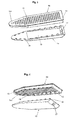
- Fig. 2 a perspective view of a hanger pad without a coating in the assembled state
- Fig. 3 an exploded view of the ironing pad without a coating obliquely from above
- Fig. 4 an exploded view of the ironing pad without a slant from below
- Fig. 5 a simplified sectional view taken along the line AA Fig. 2 ,
- the in FIG. 1 shown folding steam ironing table 1 has an ironing pad 10 and a stand device 20, wherein a coating 11 is mounted over the entire ironing pad 10.
- the stand device 20 is connected to the hanger pad 10 and comprises a scissor-type collapsible base with intersecting hingedly connected legs 21. At the remote from the ironing pad 10 end of the legs 21, these are fixed with feet 22, which allow the steam ironing table a stable position and prevent overturning of the steam ironing table.
- By changing a setting between the crossing legs 21 angle of the steam ironing table 1 can be adjusted in height and folded into a flat transport position.
- FIG. 2 shows a perspective view of the ironing pad 10 without a coating in an assembled state.
- the ironing pad 10 has a flat ironing plate 13, to which the in FIG. 1 shown cover 11 is attached. More specifically, the cover 11 is mounted on a ironing plate surface 131.
- the ironing plate 13 has a fluid-permeable part in the form of a plurality of holes 12 and a fluid-impermeable part formed of a plastic such as polypropylene, in particular expanded polypropylene (EPP). But there are also other plastic materials for the formation of the ironing plate 13 conceivable. Through the fluid-permeable part of the ironing plate 13, the fluid can flow water or steam.
- the fluid-permeable flow area of the ironing plate 13 which corresponds to the sum of the flow cross-section of all holes 12 in the ironing plate surface 131, smaller than the fluid-impermeable surface of the ironing plate surface 131.
- the holes 12 are arranged in a matrix on the ironing plate 13. In this case, depending on the size of the ironing plate 13, approximately 800 to 1200 holes may be provided on the ironing plate 13.
- FIG. 3 showing an exploded view of the ironing pad 10 without one Cover 11 shows obliquely from above, it can be seen that the ironing pad 10 composed of an upper shell 14 and a lower shell 15. Between the upper shell 14 and the lower shell 15, a cavity is formed.
- the upper shell 14 has the ironing plate 13 and one around the entire edge of the ironing plate 13 in the direction of the lower shell 15 projecting portion which is integrally connected to the ironing plate 13.
- the ironing plate surface 131 is arranged at the end remote from the projecting portion of the ironing plate 13.
- the upper shell 14 and the lower shell 15 are formed as a single trough and the ironing plate 13 is formed integrally with this trough.
- such a trained ironing pad is a single component.
- the force applied to the ironing plate 13 during ironing is transmitted through the lower shell 15 or the trough to the standing device 20.
- no reinforcing elements for stabilizing the ironing plate 13 are necessary, since the ironing plate 13 is supported by the pan or the lower shell and thus an inadmissible bending of the ironing plate 13 is prevented during the ironing process.
- the ironing pads 10 of the aforementioned embodiments or parts of the ironing pad 10 can be produced, for example, by an injection molding process.
- the continuous through the ironing plate 13 holes 12 are connected to the resulting between the lower shell 15 and upper shell 14 cavity.
- the lower shell 15 has a channel 16 extending over a part of the lower shell 15 in which the means for adjusting an air flow, such as a fan, not shown in the figures, is arranged.
- the lower shell 15 has an opening 17, through which through the fan air from the Sucked in the environment or on the sucked in by the fan steam in the environment. It should be noted that, for the above embodiment, in which the ironing plate 13 is integrally formed with the trough, the opening must be formed so that the fan can be inserted into the ironing base.
- the lower shell 15 has a plurality of projections 18 which are provided in the upper shell 14 recesses 19, which in the FIG. 4 are visible, can be introduced to connect the lower shell 15 with the upper shell 14.
- the recesses 19 are provided in the protruding from the edge of the ironing plate 13 section.
- mounting the lower shell 15 with the upper shell 14 conceivable.
- they are welded, clamped, glued or pressed together as an alternative to the aforementioned fastening.
- the upper shell 14 and the lower shell 15 must be tightly connected to each other, so that the fluid is sucked or discharged only through the holes 12 of the ironing plate 13 and / or the opening 17.
- retaining elements for holding the fan are provided on the lower shell 15 and / or upper shell 14. It is also conceivable that air guide elements are provided on the lower shell 15 and / or the upper shell to direct the sucked by the fan in the cavity fluid in the desired direction to the opening 17 and / or the holes 12 of the ironing plate.
- FIG. 5 shows a simplified sectional view of the assembled ironing pad 10 along the line AA FIG. 1 , How out FIG. 5 it can be seen, a plurality of holes 12 are provided in the ironing plate 12.
- the thickness of the ironing plate 13 corresponds to the distance between the ironing plate surface 131 and a ironing plate surface 141 which corresponds to the surface of the ironing plate 13 facing the lower casing 15.
- the holes 12 are in the in Fig. 5 illustrated embodiment, a flow cross-section, which increases starting from the ironing plate surface 141 to the ironing plate surface 131. in the As a result, the holes 12 have a conical shape. There are also other embodiments conceivable in which the holes 12 can take a different shape.
- the diameter in this application is understood to mean the diameter which is present in a flow cross-sectional area that is in one plane with the ironing plate surface 131.
- This embodiment has the advantage that this ironing pad 10 is particularly light because plastic is a poor conductor of heat, it is ensured that the heat loss from the cavity of the ironing pad 10 is low.
- the upper shell 14 is made of plastic and the lower shell of another material, such as metal.
Landscapes
- Engineering & Computer Science (AREA)
- Textile Engineering (AREA)
- Irons (AREA)
Abstract
Description
- Die Erfindung betrifft einen Dampfbügeltisch mit einer, eine Hohlkammer umschließenden Bügelunterlage, die an ihrer Oberseite eine Bügelplatte mit fluiddurchlässigen Bereichen und fluidundurchlässigen Bereichen und darunter die Hohlkammer aufweist, und mit einem Mittel zum Erzeugen einer Luftströmung innerhalb der Hohlkammer, wobei der fluiddurchlässige Teil durch eine Vielzahl von Löchern gebildet ist, deren Durchmesser jeweils kleiner ist als die Dicke der Bügelplatte.
- Aus dem Stand der Technik ist bereits eine Vielzahl von Dampfbügeltischen bekannt. Diese Dampfbügeltische besitzen eine Wanne, innerhalb der ein Mittel zum Erzeugen einer Luftströmung, wie beispielsweise ein Lüfter, angeordnet ist. Die Wanne wird mit einem Streckmetallgitter abgedeckt, wobei sich zwischen der Wanne und dem Streckmetallgitter ein Hohlraum ausbildet. Auf das Streckmetallgitter wird ein Überzug, der beispielsweise eine Polsterung beinhaltet und als Bügelfläche dient, angebracht. Genauer gesagt wird auf die Bügelfläche die Kleidung des Benutzers während des Bügelvorgangs gelegt. Ein derartig ausgebildeter Dampfbügeltisch ist beispielsweise aus der
EP 1 705 284 A1 bekannt. - Dabei ist aus dem Stand der Technik bekannt, dass der Lüfter innerhalb der Dampfbügeltische derart betrieben wird, dass sich innerhalb des durch das Streckmetallgitter und die Wanne begrenzten Hohlraums ein Überdruck oder ein Unterdruck relativ zum Umgebungsdruck ausbilden kann.
- Die aus dem Stand der Technik bekannten Dampfbügeltische weisen den Nachteil auf, dass die Öffnungen des Streckmetallgitters über die Dampf angesaugt bzw. Luft abgegeben wird groß sind. Große Öffnungen bewirken, dass der Lüfter innerhalb des Hohlraums einen im Vergleich zu dem Umgebungsdruck großen Unterdruck erzeugen muss, um einen vorgegebenen Fluidstrom, wie z.B. einen Dampfstrom oder einen Luftstrom, zu erzeugen. Zur Erzeugung eines großen Unterdrucks wird ein großer Lüfter benötigt, der im Betrieb laut und somit für den Benutzer des Dampfbügeltisches störend ist.
- Ferner sind aus der
WO 2007/121758 A1 Bügelunterlagen bekannt, die eine Vielzahl von matrixförmig angeordneten Strömungskanälen zum Durchlass von Dampfströmungen aufweisen. Auch dieEP0843040 A1 beschreibt eine derartige Bügelunterlage. Diese Bügelunterlagen haben allerdings den Nachteil, dass sie entweder aus Metall gefertigt sind oder zumindest metallische Verstärkungselemente benötigen, damit sie die mechanischen Belastungen durch das heiße, mit Druck gegen die Bügelunterlage angestellte Bügeleisen ertragen können. Aus diesem Grund sind diese Bügelunterlagen vergleichsweise teuer in der Herstellung und weisen ein vergleichsweise hohes Gewicht auf. - Es ist die Aufgabe der vorliegenden Erfindung, einen Dampfbügeltisch bereitzustellen, der bei geringem Gewicht kostengünstig herstellbar ist und dennoch im Betrieb einen ausreichenden Fluidstrom ansaugen kann.
- Diese Aufgabe wird durch einen Dampfbügel gelöst, der erfindungsgemäß dadurch gekennzeichnet ist, dass die Bügelunterlage eine Oberschale und eine Unterschale aufweist, wobei die Oberschale und die Unterschale den Hohlraum zwischen sich einschließen und zumindest die Oberschale aus expandiertem, insbesondere expandiertem Polypropylen (EPP) gefertigt ist. Vorteilhafte Ausgestaltungen der Erfindung werden in den Unteransprüchen genannt.
- Die Erfindung weist den Vorteil auf, dass eine Bügelplatte, die ausschließlich aus Kunststoff ausgebildet ist, leichter ist als eine Bügelplatte, die ein Steckmetallgitter oder metallische Verstärkungen aufweist. Im Ergebnis wird der gesamte Dampfbügeltisch leichter, was die Handhabung des Dampfbügeltisches für den Benutzer vereinfacht. Des Weiteren besteht ein weiterer Vorteil in der Verwendung einer aus Kunststoff ausgebildeten Bügelplatte darin, dass sie Wärme schlechter als Metall, im Vergleich zu verstärkten Kunststoffplatten aber gleichmäßig schlecht leitet. Im Ergebnis reduzieren sich bei einer Verwendung einer aus Kunststoff bestehenden Bügelplatte die Wärmeverluste der Bügelvorrichtung.
- Ferner besteht ein Vorteil bei einer Verwendung von Kunststoff als Material für die Bügelplatte, dass Kunststoff Schall besser absorbiert als das Metall des Steckmetallgitters. Somit reduziert sich die von dem Benutzer wahrgenommene Lautstärke, die durch das Mittel zum Einstellen der Luftströmung erzeugt wird, was die Benutzer als angenehm empfinden. Ein weiterer Vorteil der Erfindung besteht darin, dass Kunststoff im Gegensatz zu Metall nicht korrodiert, wodurch sich die Lebenszeit des Dampfbügeltisches erhöht.
- Damit die mechanischen Belastungen dauerhaft ertragen werden können, wird erfindungsgemäß insbesondere ein expandiertes Polypropylen (EPP) verwendet, es kann aber auch ein strahlenvernetzter Polypropylen Verwendung finden, dessen mechanische Eigenschaften durch Bestrahlung mit Gammastrahlung verbessert wurden, so dass sich zusätzliche Vernetzungen der Makromoleküle ergeben, die zu einer höheren Zähigkeit und Wärmebeständigkeit führen. Beide Materialien sind erfindungsgemäß geschäumt, wobei der Schaum integral ausgebildet sein kann, so dass sich eine weiche Oberfläche und eine härtere Unterschicht mit einem höheren Volumengewicht zum Aufnehmen der Biegebelastung ergeben.
- Der Dampfbügeltisch weist eine hohle Bügelunterlage mit einer Bügelplatte mit einer Vielzahl von Löchern, durch die Dampf bzw. Luft strömt, auf. Die hohle Bügelunterlage ist dabei von der Oberschale und der Unterschale gebildet, die unmittelbar oder mittelbar über Zwischenelemente miteinander verbunden sein können. Beide Elemente können auch von einem gemeinsamen Bauteil gebildet sein.
- Der Durchmesser der Löcher in der Oberschale ist dabei kleiner als die Dicke der Bügelplatte. Durch derart dimensionierte Löcher wird im Vergleich zu den Öffnungen des Steckmetallgitters, die einen Durchmesser aufweisen, der deutlich größer ist als die Dicke des Streckmetallgitters, erreicht, dass sich die Strömungsgeschwindigkeit des durch die Löcher strömenden Fluids erhöht. Folglich kann der Lüfter im Vergleich zu einem Lüfter bei der Verwendung des Streckmetallgitters kleiner sein, um den gleichen Fluidstrom anzusaugen. Im Ergebnis wird weniger Bauraum innerhalb der Bügelunterlage für den Lüfter benötigt und die im Betrieb des Lüfters erzeugte Lautstärke verringert sich. Des Weiteren wird durch die kleinen Löcher sichergestellt, dass insbesondere der über die Löcher angesaugte Fluidstrom gerichtet in den Hohlraum der Bügelunterlage einströmt. Im Ergebnis verringern sich dadurch die Strömungsverluste des Fluidstroms.
- Eine weitere vorteilhafte Ausgestaltung der Erfindung besteht darin, dass eine fluiddurchlässige Strömungsfläche der Bügelplatte, die der Summe des Strömungsquerschnitts aller Löcher in einer Bügelplattenoberfläche entspricht, kleiner ist als eine fluidundurchlässige Fläche der Bügelplattenoberfläche. Dadurch verringert sich im Vergleich zum Streckmetallgitter der Wärmeverlust des Dampfbügeltisches, da in der Erfindung die Wärmeaustauschfläche des in einem Hohlraum befindlichen Dampfs mit der Umgebungsluft aufgrund der zuvor genannten Ausbildung der Löcher klein ist. Da die Öffnungen des Streckmetallgitters im Vergleich zu dessen Dicke einen großen Durchmesser aufweisen, ist bei einem Streckmetallgitter die Wärmeaustauschfläche für einen Wärmeaustausch zwischen dem im Hohlraum befindlichen erhitzten Dampf und der Umgebungstemperatur und damit der Wärmeverlust groß.
- Ferner besteht eine vorteilhafte Ausgestaltung der Erfindung darin, dass der fluidundurchlässige Teil der Bügelplatte aus Kunststoff ausgebildet ist. Die Verwendung von Kunststoff für die Bügelplatte bietet den Vorteil, dass die Herstellung der Bügelplatte und der Bügelunterlage deutlich einfacher und günstiger erfolgen kann als die Herstellung des Steckmetallgitters. Ein weiterer Vorteil einer Bügelplatte, die aus Kunststoff ausgebildet ist, besteht darin, dass sie leichter ist als ein Steckmetallgitter. Im Ergebnis wird der gesamte Dampfbügeltisch leichter, was die Handhabung des Dampfbügeltisches für den Benutzer vereinfacht.
- Des Weiteren besteht ein weiterer Vorteil in der Verwendung einer aus Kunststoff ausgebildeten Bügelplatte darin, dass sie Wärme schlechter leitet als Metall. Im Ergebnis reduzieren sich bei einer Verwendung einer aus Kunststoff bestehenden Bügelplatte die Wärmeverluste der Bügelunterlage. Ferner besteht ein Vorteil bei einer Verwendung von Kunststoff als Material für die Bügelplatte, dass Kunststoff Schall besser absorbiert als das Metall des Steckmetallgitters. Somit reduziert sich die von dem Benutzer wahrgenommene Lautstärke, die durch das Mittel zum Einstellen der Luftströmung erzeugt wird, was die Benutzer als angenehm empfinden. Ein weiterer Vorteil der Erfindung besteht darin, dass Kunststoff im Gegensatz zu Metall nicht korrodiert, wodurch sich die Lebenszeit des Dampfbügeltisches erhöht.
- Des Weiteren besteht eine weitere vorteilhafte Ausgestaltung der Erfindung darin, dass die Löcher einen sich über die Dicke der Bügelplatte veränderliche Strömungsfläche aufweisen. So können die Löcher beispielsweise konisch ausgebildet sein. Eine derartige Ausbildung der Löcher bewirkt eine weitere Erhöhung der Strömungsgeschwindigkeit des angesaugten Dampfs. Im Ergebnis kann ein kleineres Mittel zum Erzeugen einer Luftströmung verwendet werden, um die Strömungsgeschwindigkeit des angesaugten Dampfs zu erhöhen.
- Weitere Merkmale der Erfindung ergeben sich aus den Unteransprüchen und der nachfolgenden Beschreibung, eines Ausführungsbeispiels.
- In den Zeichnungen ist der Erfindungsgegenstand schematisch dargestellt und wird anhand der Figuren nachfolgend beschrieben, wobei gleich wirkende Elemente mit denselben Bezugszeichen versehen sind. Dabei zeigen:
-
Fig. 1 eine perspektivische Ansicht eines Dampfbügeltisches, -
Fig. 2 eine perspektivische Ansicht einer Bügelunterlage ohne einen Überzug im zusammengebauten Zustand, -
Fig. 3 eine Explosionsansicht der Bügelunterlage ohne einen Überzug von schräg oben, -
Fig. 4 eine Explosionsansicht der Bügelunterlage ohne einen Überzug von schräg unten, -
Fig. 5 eine vereinfachte Schnittansicht entlang der Linie A-A ausFig. 2 . - Der in
Figur 1 gezeigte zusammenklappbare Dampfbügeltisch 1 weist eine Bügelunterlage 10 und eine Standvorrichtung 20 auf, wobei ein Überzug 11 über die gesamte Bügelunterlage 10 angebracht ist. Die Standvorrichtung 20 ist mit der Bügelunterlage 10 verbunden und umfasst ein scherenarmartiges zusammenklappbares Untergestell mit sich kreuzenden gelenkig miteinander verbundenen Standbeinen 21. An dem von der Bügelunterlage 10 entfernten Ende der Standbeine 21 sind diese mit Standfüßen 22 befestigt, die dem Dampfbügeltisch eine stabile Position ermöglichen und ein Umkippen des Dampfbügeltisches verhindern. Durch eine Änderung eines sich zwischen den sich kreuzenden Standbeinen 21 einstellenden Winkels kann der Dampfbügeltisch 1 höhenverstellt und in eine flache Transportstellung zusammengeklappt werden. -
Figur 2 zeigt eine perspektivische Ansicht der Bügelunterlage 10 ohne einen Überzug in einem zusammengebauten Zustand. Die Bügelunterlage 10 weist eine flache Bügelplatte 13 auf, auf die der inFigur 1 gezeigte Überzug 11 angebracht wird. Genauer gesagt wird der Überzug 11 auf eine Bügelplattenoberfläche 131 angebracht. Die Bügelplatte 13 weist einen fluiddurchlässigen Teil in Form einer Vielzahl von Löchern 12 und einen fluidundurchlässigen Teil auf, der aus einem Kunststoff, wie beispielsweise Polypropylen, insbesondere expandiertem Polypropylen (EPP), ausgebildet ist. Es sind aber auch noch andere Kunststoffmaterialien für die Ausbildung der Bügelplatte 13 denkbar. Durch den fluiddurchlässigen Teil der Bügelplatte 13 kann das Fluid Wasser oder Dampf strömen. - Dabei ist die fluiddurchlässige Strömungsfläche der Bügelplatte 13, die der Summe des Strömungsquerschnitts aller Löcher 12 in der Bügelplattenoberfläche 131 entspricht, kleiner als die fluidundurchlässige Fläche der Bügelplattenoberfläche 131. Die Löcher 12 sind matrixförmig auf der Bügelplatte 13 angeordnet. Dabei können abhängig von der Abmessung der Bügelplatte 13 ungefähr 800 bis 1200 Löcher auf der Bügelplatte 13 vorgesehen sein.
- Aus
Fig. 3 , die eine Explosionsansicht der Bügelunterlage 10 ohne einen Überzug 11 von schräg oben zeigt, ist ersichtlich, dass sich die Bügelunterlage 10 aus einer Oberschale 14 und einer Unterschale 15 zusammensetzt. Zwischen der Oberschale 14 und der Unterschale 15 bildet sich ein Hohlraum aus. Die Oberschale 14 weist die Bügelplatte 13 und einen um den gesamten Rand der Bügelplatte 13 in Richtung zu der Unterschale 15 vorstehenden Abschnitt auf, der mit der Bügelplatte 13 einstückig verbunden ist. Die Bügelplattenoberfläche 131 ist dabei an dem dem vorstehenden Abschnitt entfernten Ende der Bügelplatte 13 angeordnet. - In dieser Ausführungsform ist die in
Figur 1 gezeigte Standvorrichtung 20 mit der Unterschale 15 verbunden. Es sind aber auch noch eine in den Figuren nicht gezeigte Ausführungsform vorstellbar, in der die Oberschale 14 und die Unterschale 15 als eine einzige Wanne ausgebildet sind und die Bügelplatte 13 mit dieser Wanne einstückig ausgebildet ist. Im Ergebnis ist eine derartig ausgebildete Bügelunterlage ein einziges Bauteil. In einer derartigen Ausführungsform ist die inFigur 1 gezeigte Standvorrichtung 20 mit der Wanne verbunden. - In beiden zuvor genannten Ausführungsformen wird die beim Bügeln auf die Bügelplatte 13 aufgebrachte Kraft durch die Unterschale 15 bzw. die Wanne auf die Standvorrichtung 20 übertragen. Somit sind keine Verstärkungselemente zur Stabilisierung der Bügelplatte 13 nötig, da die Bügelplatte 13 durch die Wanne bzw. die Unterschale getragen wird und somit ein unzulässiges Durchbiegen der Bügelplatte 13 während des Bügelvorgangs verhindert wird. Die Bügelunterlageen 10 der zuvor genannten Ausführungsformen oder Teile der Bügelunterlage 10 können beispielsweise durch ein Spritzgussverfahren hergestellt werden.
- Die durch die Bügelplatte 13 durchgehenden Löcher 12 sind mit dem sich zwischen der Unterschale 15 und Oberschale 14 entstehenden Hohlraum verbunden. Die Unterschale 15 weist einen sich über einen Teil der Unterschale 15 erstreckenden Kanal 16 auf, in dem das in den Figuren nicht dargestellte Mittel zum Einstellen einer Luftströmung, wie beispielsweise ein Lüfter, angeordnet ist. Des Weiteren weist die Unterschale 15 eine Öffnung 17 auf, über die durch den Lüfter Luft aus der Umgebung angesaugt bzw. über die der durch den Lüfter angesaugte Dampf in die Umgebung abgegeben wird. Es ist anzumerken, dass für die oben genannte Ausführungsform, in der die Bügelplatte 13 mit der Wanne einstückig ausgebildet ist, die Öffnung derart geformt werden muss, dass der Lüfter in die Bügelunterlage eingebracht werden kann.
- Ferner weist die Unterschale 15 eine Vielzahl von Vorsprüngen 18 auf, die in in der Oberschale 14 vorgesehene Aussparungen 19, die in der
Figur 4 ersichtlich sind, eingeführt werden können, um die Unterschale 15 mit der Oberschale 14 zu verbinden. Dabei sind die Aussparungen 19 in dem von dem Rand der Bügelplatte 13 vorstehenden Abschnitt vorgesehen. Es sind auch noch weitere Befestigungsmöglichkeiten der Unterschale 15 mit der Oberschale 14 vorstellbar. So ist es vorstellbar, dass diese alternativ zu der zuvor genannten Befestigungsart miteinander verschweißt, verklemmt, verklebt oder verpresst werden. Die Oberschale 14 und die Unterschale 15 müssen dicht miteinander verbunden werden, so dass das Fluid nur durch die Löcher 12 der Bügelplatte 13 und/ oder die Öffnung 17 angesaugt bzw. abgegeben wird. - Des Weiteren ist es vorstellbar, dass an der Unterschale 15 und/ oder Oberschale 14 in den Zeichnungen nicht dargestellte Haltelemente zum Halten des Lüfters vorgesehen sind. Auch ist es vorstellbar, dass Luftleitelemente auf der Unterschale 15 und/ oder der Oberschale vorgesehen sind, um das durch den Lüfter in den Hohlraum angesaugte Fluid, in die gewünschte Richtung zu der Öffnung 17 und/ oder den Löchern 12 der Bügelplatte zu lenken.
-
Figur 5 zeigt eine vereinfachte Schnittansicht der zusammengebauten Bügelunterlage 10 entlang der Linie A-A ausFigur 1 . Wie ausFigur 5 ersichtlich ist, sind in der Bügelplatte 12 eine Vielzahl von Löchern 12 vorgesehen. Die Dicke der Bügelplatte 13 entspricht dem Abstand zwischen der Bügelplattenoberfläche 131 und einer Bügelplattenfläche 141 die der zur Unterschale 15 zeigenden Fläche der Bügelplatte 13 entspricht. Die Löcher 12 weisen in der inFig. 5 dargestellten Ausführungsform einen Strömungsquerschnitt auf, der sich beginnend von der Bügelplattenfläche 141 zu der Bügelplattenoberfläche 131 erhöht. Im Ergebnis weisen die Löcher 12 eine konische Form auf. Es sind auch noch andere Ausführungsformen vorstellbar, in denen die Löcher 12 eine andere Form einnehmen können. Als Durchmesser wird in dieser Anmeldung der Durchmesser verstanden, der in einer Strömungsquerschnittsfläche vorliegt, die mit der Bügelplattenoberfläche 131 in einer Ebene ist. - In der in den
Figuren 2 bis 5 gezeigten Bügelunterlage 10 ist sowohl die Oberschale 14 mit der Bügelplatte 13 als auch die Unterschale 15 aus einem Kunststoff, wie beispielsweise einem geschäumten Polypropylen gefertigt. Diese Ausführungsform weist den Vorteil auf, dass diese Bügelunterlage 10 besonders leicht ist Da Kunststoff ein schlechter Wärmeleiter ist, ist sichergestellt, dass der Wärmeverlust aus dem Hohlraum der Bügelunterlage 10 gering ist. Es sind aber auch Ausführungsformen vorstellbar, in denen die Oberschale 14 aus Kunststoff und die Unterschale aus einem anderen Material, wie beispielsweise Metall gefertigt ist. - Im Folgenden wird kurz der Betrieb des Dampfbügeltisches erläutert. Abhängig davon wie der Lüfter betrieben wird, bildet sich innerhalb des Hohlraums bezüglich des Umgebungsdrucks ein Unterdruck oder ein Überdruck aus. Für den Fall, dass sich ein Unterdruck innerhalb des Hohlraums ausbildet wird der durch ein Bügeleisen erzeugte Dampf über die zu bügelnde Kleidung, den Überzug und die Löcher 12 der Bügelplatte 13 in den Hohlraum angesaugt. Bei einem Durchströmen der konisch ausgebildeten Löcher 12 erhöht sich die Geschwindigkeit des Dampfstroms. Innerhalb des Hohlraums wird der Dampf durch Luftleitelemente zu dem Lüfter umgelenkt und verlässt den Hohlraum der Bügelunterlage über die Öffnung 17.
- Für den Fall, dass sich ein Überdruck innerhalb des Hohlraums ausbildet, wird durch den Lüfter über die Öffnung 17 Umgebungsluft angesaugt. Die angesaugte Luft wird innerhalb des Hohlraums durch die Luftleitelemente zu der Bügelplatte 13 umgeleitet. Im Ergebnis verlässt ein Teil der angesaugten Luft den Hohlraum durch die Löcher 12 der Bügelplatte 13. Der andere Teil der angesaugten Luft bleibt im Hohlraum, wodurch sich im Hohlraum bezüglich dem Umgebungsdruck ein Überdruck einstellt. Der Überdruck innerhalb des Hohlraums bewirkt, dass auf den fluidundurchlässigen Teil der Bügelplatte 13 eine Kraft ausgeübt, die ein Spannen der Bügelplatte 13 verursacht. Ein derartiges Spannen der Bügelplatte 13 ermöglicht ein für den Benutzer einfacheres Bügeln.
- 1 Dampfbügeltisch
- 10 Bügelunterlage
- 11 Überzug
- 12 Löcher
- 13 Bügelplatte
- 14 Oberschale
- 15 Unterschale
- 16 Kanal
- 17 Öffnung
- 18 Vorsprung
- 19 Aussparung
- 20 Standvorrichtung
- 21 Standbein
- 22 Standfuß
- 131 Bügelplattenoberfläche
- 141 Bügelplattenfläche
Claims (11)
- Dampfbügeltisch (1) mit einer, eine Hohlkammer umschließenden Bügelunterlage (10), die an ihrer Oberseite eine Bügelplatte (13) mit fluiddurchlässigen Bereichen und fluidundurchlässigen Bereichen und darunter die Hohlkammer aufweist, und mit einem Mittel zum Erzeugen einer Luftströmung innerhalb der Hohlkammer, wobei der fluiddurchlässige Teil durch eine Vielzahl von Löchern (12) gebildet ist, deren Durchmesser jeweils kleiner ist als die Dicke der Bügelplatte (13), dadurch gekennzeichnet, dass die Bügelunterlage (10) eine Oberschale (14) und eine Unterschale (15) aufweist, wobei die Oberschale (14) und die Unterschale (15) den Hohlraum zwischen sich einschließen und zumindest die Oberschale (14) aus expandiertem, insbesondere expandiertem Polypropylen (EPP) gefertigt ist.
- Dampfbügeltisch (1) nach Anspruch 1, dadurch gekennzeichnet, dass die fluiddurchlässige Bereiche der Oberfläche (131) der Bügelplatte (13) in der Summe kleiner sind als die fluidundurchlässigen Bereiche der Oberfläche (131) der Bügelplatte.
- Dampfbügeltisch (1) nach einem der beiden vorhergehenden Ansprüche, dadurch gekennzeichnet, dass die Löcher (12) einen sich über die Dicke der Bügelplatte (13) veränderlichen Strömungskanaldurchmesser, insbesondere einen konischen Strömungskanal aufweisen.
- Dampfbügeltisch (1) nach einem der vorhergehenden Ansprüche, dadurch gekennzeichnet, dass 800 bis 1200 Löcher (12) vorgesehen sind, die einen Durchmesser zwischen 4 und 10 mm, insbesondere zwischen 6 und 8 mm aufweisen und matrixförmig angeordnet sind..
- Dampfbügeltisch (1) nach einem der vorhergehenden Ansprüche, dadurch gekennzeichnet, dass die Dicke der Bügelplatte 9 bis 12 mm beträgt.
- Dampfbügeltisch (1) nach einem der vorhergehenden Ansprüche, dadurch gekennzeichnet, dass die Oberschale (13) aus einem integral geschäumten Kunststoff besteht, wobei die Porengröße des Kunststoffschaums auf der Oberseite größer als auf der Unterseite ist, so dass sich eine weiche Oberfläche und eine härtere Unterseite mit im Vergleich zur Oberfläche größeren Volumengewicht ergibt.
- Dampfbügeltisch (1) nach einem der vorhergehenden Ansprüche, dadurch gekennzeichnet, dass der Dampfbügeltisch (1) eine Standvorrichtung (20) aufweist, wobei die Standvorrichtung (20) mit der Bügelvorrichtung (10) fest oder lösbar verbunden ist.
- Dampfbügeltisch (1) nach einem der vorhergehenden Ansprüche, dadurch gekennzeichnet, dass die Unterschale (15) einstückig mit der Oberschale (14) ausgebildet ist.
- Dampfbügeltisch (1) nach einem der Ansprüche 1 bis 7, dadurch gekennzeichnet, dass die Unterschale (15) über längst des Randes angeordnete Klemmelemente mit der Oberschale (14) verbunden ist.
- Dampfbügeltisch (1) nach dem vorhergehenden Anspruch, dadurch gekennzeichnet, dass die Unterschale (15) aus Metall gefertigt ist.
- Dampfbügeltisch (1) nach einem der Ansprüche 1 bis 9, dadurch gekennzeichnet, dass die Unterschale (15) aus Kunststoff, insbesondere aus dem gleichen Kunststoff wie die Oberschale (13) gefertigt ist.
Applications Claiming Priority (2)
| Application Number | Priority Date | Filing Date | Title |
|---|---|---|---|
| DE200910058924 DE102009058924A1 (de) | 2009-12-17 | 2009-12-17 | Dampfbügeltisch |
| DE200910058909 DE102009058909A1 (de) | 2009-12-17 | 2009-12-17 | Dampfbügeltisch |
Publications (2)
| Publication Number | Publication Date |
|---|---|
| EP2336422A1 true EP2336422A1 (de) | 2011-06-22 |
| EP2336422B1 EP2336422B1 (de) | 2019-10-23 |
Family
ID=43728804
Family Applications (1)
| Application Number | Title | Priority Date | Filing Date |
|---|---|---|---|
| EP10195825.4A Not-in-force EP2336422B1 (de) | 2009-12-17 | 2010-12-17 | Dampfbügeltisch |
Country Status (1)
| Country | Link |
|---|---|
| EP (1) | EP2336422B1 (de) |
Citations (5)
| Publication number | Priority date | Publication date | Assignee | Title |
|---|---|---|---|---|
| DE8914772U1 (de) * | 1989-01-09 | 1990-02-15 | N.V. Philips' Gloeilampenfabrieken, Eindhoven | Bügeltisch |
| DE4105888A1 (de) * | 1991-02-25 | 1992-08-27 | Veit Gmbh & Co | Buegel- oder finisherpuppen-oberflaeche aus einem formteil und verfahren zum herstellen eines formteiles |
| EP0843040A1 (de) | 1996-11-15 | 1998-05-20 | ESSE85 S.r.l. | Bügeltisch mit Saugvorrichtung |
| EP1705284A1 (de) | 2005-03-22 | 2006-09-27 | Hailo-Werk Rudolf Loh GmbH & Co. KG | Dampfbügeltisch mit Mittel zum Erzeugen einer Luftströmung |
| WO2007121758A1 (de) | 2006-04-18 | 2007-11-01 | Veit Gmbh | Bügeltisch |
Family Cites Families (2)
| Publication number | Priority date | Publication date | Assignee | Title |
|---|---|---|---|---|
| DE10162734B4 (de) * | 2001-12-20 | 2007-11-08 | Leifheit Ag | Bügeltischplatte und Bügeltisch |
| US20070044350A1 (en) * | 2005-08-31 | 2007-03-01 | Ching-Song Tang | Ironing board |
-
2010
- 2010-12-17 EP EP10195825.4A patent/EP2336422B1/de not_active Not-in-force
Patent Citations (5)
| Publication number | Priority date | Publication date | Assignee | Title |
|---|---|---|---|---|
| DE8914772U1 (de) * | 1989-01-09 | 1990-02-15 | N.V. Philips' Gloeilampenfabrieken, Eindhoven | Bügeltisch |
| DE4105888A1 (de) * | 1991-02-25 | 1992-08-27 | Veit Gmbh & Co | Buegel- oder finisherpuppen-oberflaeche aus einem formteil und verfahren zum herstellen eines formteiles |
| EP0843040A1 (de) | 1996-11-15 | 1998-05-20 | ESSE85 S.r.l. | Bügeltisch mit Saugvorrichtung |
| EP1705284A1 (de) | 2005-03-22 | 2006-09-27 | Hailo-Werk Rudolf Loh GmbH & Co. KG | Dampfbügeltisch mit Mittel zum Erzeugen einer Luftströmung |
| WO2007121758A1 (de) | 2006-04-18 | 2007-11-01 | Veit Gmbh | Bügeltisch |
Also Published As
| Publication number | Publication date |
|---|---|
| EP2336422B1 (de) | 2019-10-23 |
Similar Documents
| Publication | Publication Date | Title |
|---|---|---|
| DE10243315B4 (de) | Polster für einen Fahrzeugsitz | |
| DE3609095C2 (de) | ||
| EP0662297B1 (de) | Vorrichtung zur Zubereitung von Milchschaum für Cappuccino | |
| DE102021101862A1 (de) | Sitzbaugruppe mit gepolsterten komponenten mit integriertem luftführungssystem | |
| DE202015106699U1 (de) | Luftventil für eine aufblasbare Luftmatratze oder Luftmatte | |
| DE202010005241U1 (de) | Lufttisch | |
| EP2336422B1 (de) | Dampfbügeltisch | |
| DE102008007573B4 (de) | Bügeltisch | |
| EP1793714B1 (de) | Kaffeemaschine mit flächigem ablageelement | |
| DE102005003849B3 (de) | Fahrzeugsitz mit Belüftungsvorrichtung | |
| DE102009058909A1 (de) | Dampfbügeltisch | |
| DE202010013863U1 (de) | Luftdurchlässiger Helm | |
| DE102009058924A1 (de) | Dampfbügeltisch | |
| DE102005049244A1 (de) | Padhalter | |
| DE29802756U1 (de) | Sitzbelüftung | |
| DE9307066U1 (de) | Wärmeschrank | |
| DE102004004196B4 (de) | Steppdecke | |
| DE1256044B (de) | Luftdurchlaessige Bodenplatte fuer pneumatische Einrichtungen | |
| DE20104815U1 (de) | Kanne mit Filtereinrichtung | |
| DE10235655B4 (de) | Bügeltisch | |
| EP1705284A1 (de) | Dampfbügeltisch mit Mittel zum Erzeugen einer Luftströmung | |
| DE60007582T2 (de) | Bett mit Luftstrom | |
| DE19846795A1 (de) | Polsterteil, insbesondere für Kraftfahrzeugsitze | |
| DE3240147A1 (de) | Kaffeeaufguss-perkolator | |
| DE2856498C2 (de) | Elektrische Kaffeemaschine |
Legal Events
| Date | Code | Title | Description |
|---|---|---|---|
| PUAI | Public reference made under article 153(3) epc to a published international application that has entered the european phase |
Free format text: ORIGINAL CODE: 0009012 |
|
| AK | Designated contracting states |
Kind code of ref document: A1 Designated state(s): AL AT BE BG CH CY CZ DE DK EE ES FI FR GB GR HR HU IE IS IT LI LT LU LV MC MK MT NL NO PL PT RO RS SE SI SK SM TR |
|
| AX | Request for extension of the european patent |
Extension state: BA ME |
|
| 17P | Request for examination filed |
Effective date: 20110614 |
|
| STAA | Information on the status of an ep patent application or granted ep patent |
Free format text: STATUS: EXAMINATION IS IN PROGRESS |
|
| 17Q | First examination report despatched |
Effective date: 20170328 |
|
| GRAP | Despatch of communication of intention to grant a patent |
Free format text: ORIGINAL CODE: EPIDOSNIGR1 |
|
| STAA | Information on the status of an ep patent application or granted ep patent |
Free format text: STATUS: GRANT OF PATENT IS INTENDED |
|
| INTG | Intention to grant announced |
Effective date: 20190426 |
|
| RIN1 | Information on inventor provided before grant (corrected) |
Inventor name: GAFERT, JAN Inventor name: FISCHER, KLAUS-JUERGEN Inventor name: SCHRAMM, BENJAMIN Inventor name: PAKUSA, NORBERT |
|
| GRAS | Grant fee paid |
Free format text: ORIGINAL CODE: EPIDOSNIGR3 |
|
| GRAJ | Information related to disapproval of communication of intention to grant by the applicant or resumption of examination proceedings by the epo deleted |
Free format text: ORIGINAL CODE: EPIDOSDIGR1 |
|
| GRAL | Information related to payment of fee for publishing/printing deleted |
Free format text: ORIGINAL CODE: EPIDOSDIGR3 |
|
| STAA | Information on the status of an ep patent application or granted ep patent |
Free format text: STATUS: EXAMINATION IS IN PROGRESS |
|
| GRAR | Information related to intention to grant a patent recorded |
Free format text: ORIGINAL CODE: EPIDOSNIGR71 |
|
| STAA | Information on the status of an ep patent application or granted ep patent |
Free format text: STATUS: GRANT OF PATENT IS INTENDED |
|
| GRAA | (expected) grant |
Free format text: ORIGINAL CODE: 0009210 |
|
| STAA | Information on the status of an ep patent application or granted ep patent |
Free format text: STATUS: THE PATENT HAS BEEN GRANTED |
|
| INTC | Intention to grant announced (deleted) | ||
| AK | Designated contracting states |
Kind code of ref document: B1 Designated state(s): AL AT BE BG CH CY CZ DE DK EE ES FI FR GB GR HR HU IE IS IT LI LT LU LV MC MK MT NL NO PL PT RO RS SE SI SK SM TR |
|
| INTG | Intention to grant announced |
Effective date: 20190913 |
|
| REG | Reference to a national code |
Ref country code: GB Ref legal event code: FG4D Free format text: NOT ENGLISH |
|
| REG | Reference to a national code |
Ref country code: CH Ref legal event code: EP |
|
| REG | Reference to a national code |
Ref country code: IE Ref legal event code: FG4D Free format text: LANGUAGE OF EP DOCUMENT: GERMAN |
|
| REG | Reference to a national code |
Ref country code: DE Ref legal event code: R096 Ref document number: 502010016320 Country of ref document: DE |
|
| REG | Reference to a national code |
Ref country code: AT Ref legal event code: REF Ref document number: 1193733 Country of ref document: AT Kind code of ref document: T Effective date: 20191115 |
|
| REG | Reference to a national code |
Ref country code: NL Ref legal event code: MP Effective date: 20191023 |
|
| REG | Reference to a national code |
Ref country code: LT Ref legal event code: MG4D |
|
| PG25 | Lapsed in a contracting state [announced via postgrant information from national office to epo] |
Ref country code: ES Free format text: LAPSE BECAUSE OF FAILURE TO SUBMIT A TRANSLATION OF THE DESCRIPTION OR TO PAY THE FEE WITHIN THE PRESCRIBED TIME-LIMIT Effective date: 20191023 Ref country code: PT Free format text: LAPSE BECAUSE OF FAILURE TO SUBMIT A TRANSLATION OF THE DESCRIPTION OR TO PAY THE FEE WITHIN THE PRESCRIBED TIME-LIMIT Effective date: 20200224 Ref country code: LT Free format text: LAPSE BECAUSE OF FAILURE TO SUBMIT A TRANSLATION OF THE DESCRIPTION OR TO PAY THE FEE WITHIN THE PRESCRIBED TIME-LIMIT Effective date: 20191023 Ref country code: BG Free format text: LAPSE BECAUSE OF FAILURE TO SUBMIT A TRANSLATION OF THE DESCRIPTION OR TO PAY THE FEE WITHIN THE PRESCRIBED TIME-LIMIT Effective date: 20200123 Ref country code: FI Free format text: LAPSE BECAUSE OF FAILURE TO SUBMIT A TRANSLATION OF THE DESCRIPTION OR TO PAY THE FEE WITHIN THE PRESCRIBED TIME-LIMIT Effective date: 20191023 Ref country code: NL Free format text: LAPSE BECAUSE OF FAILURE TO SUBMIT A TRANSLATION OF THE DESCRIPTION OR TO PAY THE FEE WITHIN THE PRESCRIBED TIME-LIMIT Effective date: 20191023 Ref country code: SE Free format text: LAPSE BECAUSE OF FAILURE TO SUBMIT A TRANSLATION OF THE DESCRIPTION OR TO PAY THE FEE WITHIN THE PRESCRIBED TIME-LIMIT Effective date: 20191023 Ref country code: LV Free format text: LAPSE BECAUSE OF FAILURE TO SUBMIT A TRANSLATION OF THE DESCRIPTION OR TO PAY THE FEE WITHIN THE PRESCRIBED TIME-LIMIT Effective date: 20191023 Ref country code: GR Free format text: LAPSE BECAUSE OF FAILURE TO SUBMIT A TRANSLATION OF THE DESCRIPTION OR TO PAY THE FEE WITHIN THE PRESCRIBED TIME-LIMIT Effective date: 20200124 Ref country code: NO Free format text: LAPSE BECAUSE OF FAILURE TO SUBMIT A TRANSLATION OF THE DESCRIPTION OR TO PAY THE FEE WITHIN THE PRESCRIBED TIME-LIMIT Effective date: 20200123 Ref country code: PL Free format text: LAPSE BECAUSE OF FAILURE TO SUBMIT A TRANSLATION OF THE DESCRIPTION OR TO PAY THE FEE WITHIN THE PRESCRIBED TIME-LIMIT Effective date: 20191023 |
|
| PG25 | Lapsed in a contracting state [announced via postgrant information from national office to epo] |
Ref country code: RS Free format text: LAPSE BECAUSE OF FAILURE TO SUBMIT A TRANSLATION OF THE DESCRIPTION OR TO PAY THE FEE WITHIN THE PRESCRIBED TIME-LIMIT Effective date: 20191023 Ref country code: IS Free format text: LAPSE BECAUSE OF FAILURE TO SUBMIT A TRANSLATION OF THE DESCRIPTION OR TO PAY THE FEE WITHIN THE PRESCRIBED TIME-LIMIT Effective date: 20200224 Ref country code: HR Free format text: LAPSE BECAUSE OF FAILURE TO SUBMIT A TRANSLATION OF THE DESCRIPTION OR TO PAY THE FEE WITHIN THE PRESCRIBED TIME-LIMIT Effective date: 20191023 |
|
| PG25 | Lapsed in a contracting state [announced via postgrant information from national office to epo] |
Ref country code: AL Free format text: LAPSE BECAUSE OF FAILURE TO SUBMIT A TRANSLATION OF THE DESCRIPTION OR TO PAY THE FEE WITHIN THE PRESCRIBED TIME-LIMIT Effective date: 20191023 |
|
| REG | Reference to a national code |
Ref country code: DE Ref legal event code: R097 Ref document number: 502010016320 Country of ref document: DE |
|
| PG2D | Information on lapse in contracting state deleted |
Ref country code: IS |
|
| PG25 | Lapsed in a contracting state [announced via postgrant information from national office to epo] |
Ref country code: EE Free format text: LAPSE BECAUSE OF FAILURE TO SUBMIT A TRANSLATION OF THE DESCRIPTION OR TO PAY THE FEE WITHIN THE PRESCRIBED TIME-LIMIT Effective date: 20191023 Ref country code: RO Free format text: LAPSE BECAUSE OF FAILURE TO SUBMIT A TRANSLATION OF THE DESCRIPTION OR TO PAY THE FEE WITHIN THE PRESCRIBED TIME-LIMIT Effective date: 20191023 Ref country code: CZ Free format text: LAPSE BECAUSE OF FAILURE TO SUBMIT A TRANSLATION OF THE DESCRIPTION OR TO PAY THE FEE WITHIN THE PRESCRIBED TIME-LIMIT Effective date: 20191023 Ref country code: DK Free format text: LAPSE BECAUSE OF FAILURE TO SUBMIT A TRANSLATION OF THE DESCRIPTION OR TO PAY THE FEE WITHIN THE PRESCRIBED TIME-LIMIT Effective date: 20191023 Ref country code: IS Free format text: LAPSE BECAUSE OF FAILURE TO SUBMIT A TRANSLATION OF THE DESCRIPTION OR TO PAY THE FEE WITHIN THE PRESCRIBED TIME-LIMIT Effective date: 20200223 |
|
| REG | Reference to a national code |
Ref country code: CH Ref legal event code: PL |
|
| REG | Reference to a national code |
Ref country code: BE Ref legal event code: MM Effective date: 20191231 |
|
| PLBE | No opposition filed within time limit |
Free format text: ORIGINAL CODE: 0009261 |
|
| STAA | Information on the status of an ep patent application or granted ep patent |
Free format text: STATUS: NO OPPOSITION FILED WITHIN TIME LIMIT |
|
| PG25 | Lapsed in a contracting state [announced via postgrant information from national office to epo] |
Ref country code: SM Free format text: LAPSE BECAUSE OF FAILURE TO SUBMIT A TRANSLATION OF THE DESCRIPTION OR TO PAY THE FEE WITHIN THE PRESCRIBED TIME-LIMIT Effective date: 20191023 Ref country code: MC Free format text: LAPSE BECAUSE OF FAILURE TO SUBMIT A TRANSLATION OF THE DESCRIPTION OR TO PAY THE FEE WITHIN THE PRESCRIBED TIME-LIMIT Effective date: 20191023 Ref country code: SK Free format text: LAPSE BECAUSE OF FAILURE TO SUBMIT A TRANSLATION OF THE DESCRIPTION OR TO PAY THE FEE WITHIN THE PRESCRIBED TIME-LIMIT Effective date: 20191023 Ref country code: IT Free format text: LAPSE BECAUSE OF FAILURE TO SUBMIT A TRANSLATION OF THE DESCRIPTION OR TO PAY THE FEE WITHIN THE PRESCRIBED TIME-LIMIT Effective date: 20191023 |
|
| GBPC | Gb: european patent ceased through non-payment of renewal fee |
Effective date: 20200123 |
|
| 26N | No opposition filed |
Effective date: 20200724 |
|
| PG25 | Lapsed in a contracting state [announced via postgrant information from national office to epo] |
Ref country code: FR Free format text: LAPSE BECAUSE OF NON-PAYMENT OF DUE FEES Effective date: 20191223 Ref country code: GB Free format text: LAPSE BECAUSE OF NON-PAYMENT OF DUE FEES Effective date: 20200123 Ref country code: LU Free format text: LAPSE BECAUSE OF NON-PAYMENT OF DUE FEES Effective date: 20191217 Ref country code: IE Free format text: LAPSE BECAUSE OF NON-PAYMENT OF DUE FEES Effective date: 20191217 |
|
| PG25 | Lapsed in a contracting state [announced via postgrant information from national office to epo] |
Ref country code: SI Free format text: LAPSE BECAUSE OF FAILURE TO SUBMIT A TRANSLATION OF THE DESCRIPTION OR TO PAY THE FEE WITHIN THE PRESCRIBED TIME-LIMIT Effective date: 20191023 Ref country code: LI Free format text: LAPSE BECAUSE OF NON-PAYMENT OF DUE FEES Effective date: 20191231 Ref country code: CH Free format text: LAPSE BECAUSE OF NON-PAYMENT OF DUE FEES Effective date: 20191231 Ref country code: BE Free format text: LAPSE BECAUSE OF NON-PAYMENT OF DUE FEES Effective date: 20191231 |
|
| REG | Reference to a national code |
Ref country code: AT Ref legal event code: MM01 Ref document number: 1193733 Country of ref document: AT Kind code of ref document: T Effective date: 20191217 |
|
| PG25 | Lapsed in a contracting state [announced via postgrant information from national office to epo] |
Ref country code: CY Free format text: LAPSE BECAUSE OF FAILURE TO SUBMIT A TRANSLATION OF THE DESCRIPTION OR TO PAY THE FEE WITHIN THE PRESCRIBED TIME-LIMIT Effective date: 20191023 Ref country code: AT Free format text: LAPSE BECAUSE OF NON-PAYMENT OF DUE FEES Effective date: 20191217 |
|
| PG25 | Lapsed in a contracting state [announced via postgrant information from national office to epo] |
Ref country code: HU Free format text: LAPSE BECAUSE OF FAILURE TO SUBMIT A TRANSLATION OF THE DESCRIPTION OR TO PAY THE FEE WITHIN THE PRESCRIBED TIME-LIMIT; INVALID AB INITIO Effective date: 20101217 Ref country code: MT Free format text: LAPSE BECAUSE OF FAILURE TO SUBMIT A TRANSLATION OF THE DESCRIPTION OR TO PAY THE FEE WITHIN THE PRESCRIBED TIME-LIMIT Effective date: 20191023 |
|
| PG25 | Lapsed in a contracting state [announced via postgrant information from national office to epo] |
Ref country code: TR Free format text: LAPSE BECAUSE OF FAILURE TO SUBMIT A TRANSLATION OF THE DESCRIPTION OR TO PAY THE FEE WITHIN THE PRESCRIBED TIME-LIMIT Effective date: 20191023 |
|
| PG25 | Lapsed in a contracting state [announced via postgrant information from national office to epo] |
Ref country code: MK Free format text: LAPSE BECAUSE OF FAILURE TO SUBMIT A TRANSLATION OF THE DESCRIPTION OR TO PAY THE FEE WITHIN THE PRESCRIBED TIME-LIMIT Effective date: 20191023 |
|
| PGFP | Annual fee paid to national office [announced via postgrant information from national office to epo] |
Ref country code: DE Payment date: 20231017 Year of fee payment: 14 |
|
| REG | Reference to a national code |
Ref country code: DE Ref legal event code: R082 Ref document number: 502010016320 Country of ref document: DE Representative=s name: KBN IP PATENTANWAELTE PARTNERSCHAFT MBB, DE |
|
| REG | Reference to a national code |
Ref country code: DE Ref legal event code: R119 Ref document number: 502010016320 Country of ref document: DE |
|
| PG25 | Lapsed in a contracting state [announced via postgrant information from national office to epo] |
Ref country code: DE Free format text: LAPSE BECAUSE OF NON-PAYMENT OF DUE FEES Effective date: 20250701 |