EP2335850A1 - Bohrhilfe mit einer Auffangeinrichtung für eine Flüssigkeit - Google Patents
Bohrhilfe mit einer Auffangeinrichtung für eine Flüssigkeit Download PDFInfo
- Publication number
- EP2335850A1 EP2335850A1 EP10193236A EP10193236A EP2335850A1 EP 2335850 A1 EP2335850 A1 EP 2335850A1 EP 10193236 A EP10193236 A EP 10193236A EP 10193236 A EP10193236 A EP 10193236A EP 2335850 A1 EP2335850 A1 EP 2335850A1
- Authority
- EP
- European Patent Office
- Prior art keywords
- drilling
- collecting device
- drilling aid
- aid according
- aid
- Prior art date
- Legal status (The legal status is an assumption and is not a legal conclusion. Google has not performed a legal analysis and makes no representation as to the accuracy of the status listed.)
- Withdrawn
Links
- 239000007788 liquid Substances 0.000 title claims abstract description 46
- 238000005553 drilling Methods 0.000 claims abstract description 107
- 239000000463 material Substances 0.000 claims description 23
- 239000000758 substrate Substances 0.000 claims description 19
- 229920000058 polyacrylate Polymers 0.000 claims description 6
- 229920000642 polymer Polymers 0.000 claims description 6
- 229920001875 Ebonite Polymers 0.000 claims description 4
- 239000002184 metal Substances 0.000 claims description 4
- 239000004033 plastic Substances 0.000 claims description 4
- 230000009969 flowable effect Effects 0.000 claims description 2
- MOVRNJGDXREIBM-UHFFFAOYSA-N aid-1 Chemical compound O=C1NC(=O)C(C)=CN1C1OC(COP(O)(=O)OC2C(OC(C2)N2C3=C(C(NC(N)=N3)=O)N=C2)COP(O)(=O)OC2C(OC(C2)N2C3=C(C(NC(N)=N3)=O)N=C2)COP(O)(=O)OC2C(OC(C2)N2C3=C(C(NC(N)=N3)=O)N=C2)COP(O)(=O)OC2C(OC(C2)N2C(NC(=O)C(C)=C2)=O)COP(O)(=O)OC2C(OC(C2)N2C3=C(C(NC(N)=N3)=O)N=C2)COP(O)(=O)OC2C(OC(C2)N2C3=C(C(NC(N)=N3)=O)N=C2)COP(O)(=O)OC2C(OC(C2)N2C3=C(C(NC(N)=N3)=O)N=C2)COP(O)(=O)OC2C(OC(C2)N2C(NC(=O)C(C)=C2)=O)COP(O)(=O)OC2C(OC(C2)N2C3=C(C(NC(N)=N3)=O)N=C2)COP(O)(=O)OC2C(OC(C2)N2C3=C(C(NC(N)=N3)=O)N=C2)COP(O)(=O)OC2C(OC(C2)N2C3=C(C(NC(N)=N3)=O)N=C2)COP(O)(=O)OC2C(OC(C2)N2C(NC(=O)C(C)=C2)=O)COP(O)(=O)OC2C(OC(C2)N2C3=C(C(NC(N)=N3)=O)N=C2)COP(O)(=O)OC2C(OC(C2)N2C3=C(C(NC(N)=N3)=O)N=C2)COP(O)(=O)OC2C(OC(C2)N2C3=C(C(NC(N)=N3)=O)N=C2)CO)C(O)C1 MOVRNJGDXREIBM-UHFFFAOYSA-N 0.000 description 13
- 238000001816 cooling Methods 0.000 description 11
- 239000000853 adhesive Substances 0.000 description 10
- 238000003754 machining Methods 0.000 description 9
- XLYOFNOQVPJJNP-UHFFFAOYSA-N water Substances O XLYOFNOQVPJJNP-UHFFFAOYSA-N 0.000 description 9
- 230000001070 adhesive effect Effects 0.000 description 8
- 229910003460 diamond Inorganic materials 0.000 description 6
- 239000010432 diamond Substances 0.000 description 6
- 239000012790 adhesive layer Substances 0.000 description 3
- 239000011248 coating agent Substances 0.000 description 3
- 238000000576 coating method Methods 0.000 description 3
- 239000002390 adhesive tape Substances 0.000 description 2
- 239000012530 fluid Substances 0.000 description 2
- 239000007787 solid Substances 0.000 description 2
- 101100390736 Danio rerio fign gene Proteins 0.000 description 1
- 101100390738 Mus musculus Fign gene Proteins 0.000 description 1
- 239000000110 cooling liquid Substances 0.000 description 1
- 230000001419 dependent effect Effects 0.000 description 1
- 238000013021 overheating Methods 0.000 description 1
- 230000008929 regeneration Effects 0.000 description 1
- 238000011069 regeneration method Methods 0.000 description 1
- 239000002699 waste material Substances 0.000 description 1
Images


Classifications
-
- B—PERFORMING OPERATIONS; TRANSPORTING
- B23—MACHINE TOOLS; METAL-WORKING NOT OTHERWISE PROVIDED FOR
- B23B—TURNING; BORING
- B23B49/00—Measuring or gauging equipment on boring machines for positioning or guiding the drill; Devices for indicating failure of drills during boring; Centering devices for holes to be bored
- B23B49/02—Boring templates or bushings
- B23B49/026—Boring bushing carriers attached to the workpiece by glue, magnets, suction devices or the like
-
- B—PERFORMING OPERATIONS; TRANSPORTING
- B23—MACHINE TOOLS; METAL-WORKING NOT OTHERWISE PROVIDED FOR
- B23B—TURNING; BORING
- B23B2226/00—Materials of tools or workpieces not comprising a metal
- B23B2226/39—Foam
-
- B—PERFORMING OPERATIONS; TRANSPORTING
- B23—MACHINE TOOLS; METAL-WORKING NOT OTHERWISE PROVIDED FOR
- B23B—TURNING; BORING
- B23B2250/00—Compensating adverse effects during turning, boring or drilling
- B23B2250/12—Cooling and lubrication
Definitions
- the present invention relates to a drilling aid with the features according to the preamble of claim 1.
- abrasive machining with diamond tools for example in the form of diamond drill bits
- the cutting segments of the diamond tool are cooled during the machining process by means of a cooling liquid in order to assist the machining process and to increase the life of the cutting segments.
- the liquid also serves to remove the solids removed by the diamond tool from the processing site.
- the supplied liquid is referred to as cooling and rinsing liquid and the liquid mixed with solids as dirty liquid.
- DE 198 16 733 C2 discloses a drilling aid for drilling in tiles with a mark indicating the center of the drill, ie the center of the future wellbore.
- the drilling aid is attached by means of an adhesive layer on the substrate to be processed, such as a tile.
- the known drilling aid has the disadvantage that no feeding device for the cooling and rinsing liquid and no collecting device for the dirty liquid are present.
- the cooling and rinsing liquid can be transported to the processing site via the drilling device and the drilling tool.
- a special drill with feeder is required.
- the dirty liquid is not collected, but pollutes the environment of the processing site.
- a drilling aid consisting of a base plate which can be fastened by means of an adhesive on the substrate to be processed, and a guide device for guiding a drilling tool.
- the drilling aid also has an inlet nozzle for supplying the cooling and rinsing liquid and an outlet nozzle for removing the dirty liquid.
- the outlet nozzle of the drilling aid In order to prevent the dirty liquid escaping from the outlet nozzle and splashed around, the outlet nozzle of the drilling aid must be connected to a collecting device, for example in the form of a wet vacuum cleaner. This has the disadvantage that a high expenditure on equipment is required to collect the dirty liquid.
- the object of the present invention is in contrast to further develop a drilling aid of the type mentioned in that the dirty liquid is collected by the drilling aid.
- a drilling aid with a fastening device for fastening the drilling aid to a substrate to be processed a guide device for guiding a drilling tool along a drilling direction and a collecting device for collecting and storing a dirty liquid.
- the drilling tool is at least partially surrounded by the collecting device during the guidance along the drilling direction.
- the collecting device is arranged on an inner surface of the guide device facing the drilling tool.
- the collecting device is designed in the form of a cylinder or a truncated cone with a cylindrical bore.
- the catcher is easily replaceable.
- the collecting device is formed exchangeable. This has the advantage that only the catcher must be renewed when the water storage capacity of the catcher is exhausted, and the drill can continue to be used.
- the collecting device is arranged on an end face of the guide device.
- the collecting device is particularly preferably arranged on the side of the guide device facing away from the substrate to be processed.
- the guide device and the collecting device are integrated in a common cylinder body.
- the cylinder body is made of a material to which a water-storing material is mixed or made of a water-storing material.
- the collecting device is preferably made of a flowable material, cord, sponge or a material containing polymers or polyacrylates. These materials ensure that the dirty liquid is collected and stored by the catcher.
- the use of polymers and polyacrylates has the advantage that they have a high hygroscopic property with a high water storage capacity.
- the guide device is formed of metal, plastic or a hard rubber. These materials ensure safe guidance of the drilling tool during machining and are subject to little wear by the drilling tool.
- the fastening device is integrated into the guide device at the end facing the base.
- FIGS. 1a, b show a first embodiment of a drilling aid 1 according to the invention in a perspective view ( Fig. 1a ) and a sectional view along the line AA ( Fig. 1 b) ,
- the drilling aid 1 consists of a fastening device in the form of a base plate 2, a guide device 3 and a collecting device 4.
- the base plate 2 has an adhesive 6 on a side facing a substrate 5 to be processed.
- the drilling aid 1 can be fastened by means of the adhesive 6 on the substrate 5 to be processed in a detachable manner.
- the adhesive 6 is formed, for example, as a double-sided adhesive tape or as a releasable adhesive layer.
- auxiliary lines 7, 8 which intersect at a crossing point.
- the crossing point corresponds to the center of the drill, ie the center of the future borehole.
- the Bohrmitte can be displayed on elevations or depressions which are arranged on the base plate 2 and are formed, for example, linear or arrow-shaped.
- the drilling aid 1 has a cylinder body 9 with a bore 10 , which essentially corresponds to the diameter of a drilling tool 11 .
- the drilling tool 11 is driven by rotation about a rotation axis 12 in the direction of an arrow 13 and moved along a drilling direction 14 .
- the cylinder body 9 is formed in two parts from an outer sleeve, which forms the guide device 3, and an inner coating which forms the collecting device 4.
- the guide device 3 and the collecting device 4 are arranged coaxially to the axis of rotation 12.
- the guide device 3 takes on the task of safely guiding the drilling tool 10 during machining and consists of a material with a high strength, such as metal, plastic or hard rubber.
- the collecting device 4 for the dirty liquid is constructed of a water-storing material.
- water-storing materials are, for example, flow, cord, sponge or materials that Contain polymers or polyacrylates.
- the use of polymers and polyacrylates has the advantage that they have a high hygroscopic property with a high water storage capacity. The greater the water storage capacity of the collecting device 4, the thinner the coating can be formed or the more dirty liquid can be absorbed.
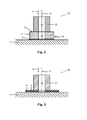
- Fig. 2 shows a second embodiment of a drilling aid 20 according to the invention with a guide device 21 for guiding the drilling tool 11 during processing and a collecting device 22 for collecting and storing the dirty liquid during processing.
- the guide device 21 is designed as a circular cylinder with a cylindrical bore 23 .
- the guide means 21 and the bore 23 are arranged coaxially with the axis of rotation 12.
- the fastening device for fastening the drilling aid 20 to the substrate 5 to be processed is integrated into the guide device 21.
- the adhesive 6, with which the drilling aid 20 can be detachably fastened to the substrate 5, is mounted on the side of the guide device 21 facing the substrate 5.
- the collecting device 22 is likewise designed as a circular cylinder with a cylindrical opening 24 .
- the collecting device 22 and the opening 24 are arranged coaxially with the axis of rotation 12.
- the collecting device 22 is arranged on the side facing away from the substrate 5 side of the guide device 21 and connected to an end face 25 of the guide device 21 with the guide device 21.
- the guide device 21 is made of a material, such as metal, plastic or hard rubber, which ensures a safe guidance of the drilling tool 11 during machining and is subject to only a small amount of wear by the drilling tool 11.
- the dirty liquid collecting means 22 is made of a water-storing material. Suitable water-storing materials are, for example, fluid, cord, sponge or materials containing polymers or polyacrylates, as well as all other materials having a water storage capacity.
- the guide device 21 and the collecting device 22 are formed in the drilling direction 14 in a stepped shape.
- the height and thickness of the guide means 21 and the catcher 22 are adapted to the different tasks.
- the guide means 21 and the catcher 22 may be configured in a flush shape.
- the bore 23 of the guide means 21 and the opening 24 of the catcher 22 must be so large that the drilling tool 11 passes through.
- the diameter of the bore 23 is slightly larger than the diameter of the drilling tool 11.
- the collecting device 22 is used only for collecting and storing the dirty liquid and not for guiding the drilling tool 11.
- the diameter of the opening 24 is selected so that the collecting device 22 during the movement of the drilling tool 11 in the drilling direction 14 is subject to low wear and can collect and store as much contaminated liquid. If the diameter of the opening 24 of the collecting device 22 is as small as possible, the dirty liquid can be collected particularly well, since there is only a small gap between the drilling tool 11 and the collecting device 22, could escape through the dirty liquid.
- the drilling aid 20 also has a supply line 26 for the cooling and rinsing liquid.
- the supply line 26 penetrates the guide device 21, guides the cooling and rinsing liquid through the guide device 21 and opens into the bore 23.
- the cooling and rinsing liquid is used, inter alia, to cool the drilling tool 11 in the region of the processing point.
- the supply line 26 should be arranged at a distance from the collecting device 22 of the drilling aid 20, so that the supplied cooling and rinsing liquid reaches the processing point and is not collected and stored by the collecting device 22.
- the cooling and rinsing liquid can be supplied via the drilling tool 11.
- Fig. 3 3 shows a third embodiment of a drilling aid 30 according to the invention.
- the drilling aid 30 has the base plate 2 for fastening the drilling aid 30 to the substrate 5 to be processed and a cylinder body 31 arranged on the base plate 2 with a bore 32 .
- the cylinder body 31 and the bore 32 are arranged coaxially with the axis of rotation 12.
- the guide device for guiding the drilling tool 11 during machining is integrated into the cylinder body 31.
- the diameter of the bore 32 substantially corresponds to the diameter of the drilling tool 11 in order to ensure reliable guidance of the drilling tool 11 during machining.
- the cylinder body 31 is made of a material to which a water-storing material is attached, or the cylinder body 31 is made entirely of a water-storing material.
- the collecting device for collecting and storing the dirty liquid is also integrated in the cylinder body 31. Suitable materials for the cylinder body 31 on the one hand ensure a guidance of the drilling tool 11 in the region of the processing site and, on the other hand, have a water storage capacity such that at least the dirty liquid produced when drilling a borehole can be received by the cylinder body 31.
- drilling aids 1, 20, 30 are designed as disposable or reusable aids and among other things intended for users who drill only occasionally with cooling and rinsing fluid and have no catcher in the form of a wet vacuum available.
- the drilling aid 1, 20, 30 is for a single use, i. designed for creating a borehole. After creating the wellbore, the drilling aid 1, 20, 30 is removed from the substrate 5 and disposed of over the waste.
- the drilling aid 1, 20, 30 is designed for a multiple application.
- the drilling aid 1, 20, 30 has a releasable, self-adhesive adhesive 6 and the collecting device 4, 22, 31 has a water storage capacity for the dirty liquid of several wells. After drilling a borehole, the drilling aid 1, 20, 30 removed from the substrate 5 and stored safely. The drilling aid 1, 20, 30 can be used until the water storage capacity of the collecting device 4, 22, 31 is exhausted.
- the drilling aid 1, 20, 30 is designed to be reusable for multiple applications.
- the drilling aid 1, 20, 30 is releasably attachable via a self-adhesive adhesive 6.
- the collecting device 4, 22, 31 releases the stored dirty liquid, for example, to pressure, so that at least part of the stored dirty liquid is released again.
- the drilling aid 1, 20, 30 can be used until the regeneration capability of the water-storing material of the collecting device 4, 22, 31 is exhausted.
- Fig. 4 shows a fourth embodiment of a drilling aid 40 according to the invention with a guide device 41 for guiding the drilling tool 11 during processing and a collecting device 42 for collecting and storing the dirty liquid.
- the guide device 41 is formed as a cylinder body with a bore 43 which is formed in the shape of a truncated cone portion and tapers in the drilling direction 14. At the end of the bore 43 facing the base 5, the diameter substantially corresponds to the diameter of the drilling tool 11, so that the drilling tool 11 is securely guided in the region of the machining point.
- the collecting device 42 is like the bore 43 of the guide means 41 also formed in the form of a truncated cone portion and arranged in the bore 43 of the guide means 41.
- the collecting device 42 has a central opening 44 , which in the embodiment of Fig. 4 is designed as a circular cylinder.
- the diameter of the circular cylinder 44 substantially corresponds to the diameter of the drilling tool eleventh
- the guide means 41 is either as in the embodiment of Fig. 4 shown arranged on the base plate 2 and fixedly connected to the base plate 2 or by means of the adhesive 6 directly to the substrate 5 fastened.
- the catcher 42 is easily replaceable. If the water storage capacity of the collecting device 42 is exhausted, the collecting device 42 is removed from the bore 43.
- drilling aid 40 according to the invention is not designed for single or multiple use, but for regular use. Only the collecting device 42 must be regularly replaced or processed, the other components of the drilling aid 40 are suitable for regular use.
- the fastening device may alternatively be designed as a suction cup.
- a suction cup generates in comparison to a double-sided adhesive tape or a releasable adhesive layer a higher holding force on the substrate to be processed 5.
- the suction cup also has the advantage that the holding force on the substrate 5 does not deteriorate even after repeated fixing, so that the drilling aid safely on the ground. 5 is attached.
Landscapes
- Engineering & Computer Science (AREA)
- Mechanical Engineering (AREA)
- Processing Of Stones Or Stones Resemblance Materials (AREA)
Abstract
Bohrhilfe (1) mit einer Befestigungseinrichtung (2) zur Befestigung der Bohrhilfe (1) an einem zu bearbeitenden Untergrund (5), einer Führungseinrichtung (3) zur Führung eines Bohrwerkzeuges (11) entlang einer Bohrrichtung (14) und einer Auffangeinrichtung (4) zum Auffangen und Speichern einer Schmutzflüssigkeit, wobei das Bohrwerkzeug (11) bei der Führung entlang der Bohrrichtung (14) von der Auffangeinrichtung (4) zumindest teilweise umgeben ist.
Description
- Die vorliegende Erfindung betrifft eine Bohrhilfe mit den Merkmalen gemäß dem Oberbegriff des Anspruchs 1.
- Bei der abrasiv abtragenden Bearbeitung mit Diamantwerkzeugen, beispielsweise in Form von Diamantbohrkronen, ist es erforderlich, das Diamantwerkzeug im Bereich der Bearbeitungsstelle zu kühlen, um eine Beschädigung des Diamantwerkzeuges durch eine Überhitzung zu vermeiden. Die Schneidsegmente des Diamantwerkzeuges werden während des Bearbeitungsvorgangs mittels einer Kühlflüssigkeit gekühlt, um den Bearbeitungsvorgang zu unterstützen und die Lebensdauer der Schneidsegmente zu erhöhen. Die Flüssigkeit dient außerdem dazu, die von dem Diamantwerkzeug abgetragenen Feststoffe von der Bearbeitungsstelle zu entfernen. Die zugeführte Flüssigkeit wird als Kühl- und Spülflüssigkeit und die mit Feststoffen versetzte Flüssigkeit als Schmutzflüssigkeit bezeichnet.
-
DE 198 16 733 C2 offenbart eine Bohrhilfe zum Bohren in Fliesen mit einer Markierung zur Kennzeichnung der Bohrmitte, d.h. des Mittelpunktes des künftigen Bohrloches. Die Bohrhilfe wird mittels einer Klebeschicht auf dem zu bearbeitenden Untergrund, beispielsweise einer Fliese, befestigt. Die bekannte Bohrhilfe hat den Nachteil, dass keine Zuführeinrichtung für die Kühl- und Spülflüssigkeit und keine Auffangeinrichtung für die Schmutzflüssigkeit vorhanden sind. Die Kühl- und Spülflüssigkeit kann über das Bohrgerät und das Bohrwerkzeug an die Bearbeitungsstelle transportiert werden. Allerdings ist ein spezielles Bohrgerät mit Zuführeinrichtung erforderlich. Die Schmutzflüssigkeit wird nicht aufgefangen, sondern verschmutzt die Umgebung der Bearbeitungsstelle. -
DE 20 2007 009 042 U1 offenbart eine Bohrhilfe bestehend aus einer Grundplatte, die mittels eines Haftmittels auf dem zu bearbeitenden Untergrund befestigbar ist, und einer Führungseinrichtung zur Führung eines Bohrwerkzeuges. Die Bohrhilfe weist außerdem einen Eingangsstutzen zur Zuführung der Kühl- und Spülflüssigkeit und einen Ausgangsstutzen zur Abführung der Schmutzflüssigkeit auf. Um zu verhindern, dass die Schmutzflüssigkeit aus dem Ausgangsstutzen austritt und umherspritzt, muss der Ausgangsstutzen der Bohrhilfe mit einer Auffangeinrichtung, beispielsweise in Form eines Nassstaubsaugers, verbunden sein. Dies hat den Nachteil, dass ein hoher apparativer Aufwand erforderlich ist, um die Schmutzflüssigkeit aufzufangen. - Die Aufgabe der vorliegenden Erfindung besteht demgegenüber darin, eine Bohrhilfe der eingangs genannten Art dahingehend weiterzuentwickeln, dass die Schmutzflüssigkeit von der Bohrhilfe aufgefangen wird.
- Diese Aufgabe wird bei der eingangs genannten Bohrhilfe erfindungsgemäß durch die Merkmale des unabhängigen Anspruchs 1 gelöst. Vorteilhafte Ausgestaltungen ergeben sich aus den abhängigen Ansprüchen.
- Es wird eine Bohrhilfe mit einer Befestigungseinrichtung zur Befestigung der Bohrhilfe an einem zu bearbeitenden Untergrund, einer Führungseinrichtung zur Führung eines Bohrwerkzeuges entlang einer Bohrrichtung und einer Auffangeinrichtung zum Auffangen und Speichern einer Schmutzflüssigkeit vorgeschlagen. Erfindungsgemäß ist das Bohrwerkzeug bei der Führung entlang der Bohrrichtung von der Auffangeinrichtung zumindest teilweise umgeben. Dies hat den Vorteil, dass die Schmutzflüssigkeit bei der Bearbeitung von der Bohrhilfe aufgenommen und gespeichert wird und keine zusätzliche Auffangeinrichtung für die Schmutzflüssigkeit erforderlich ist, so dass der apparative Aufwand reduziert ist.
- In einer bevorzugten Ausführung ist die Auffangeinrichtung auf einer dem Bohrwerkzeug zugewandten Innenfläche der Führungseinrichtung angeordnet. Diese Ausführung hat den Vorteil, dass die Schmutzflüssigkeit besonders gut aufgefangen werden kann, da zwischen der Auffangeinrichtung und dem Bohrwerkzeug nur ein geringer Spalt besteht, durch den Schmutzflüssigkeit entweichen kann.
- Besonders bevorzugt ist die Auffangeinrichtung in Form eines Zylinders oder eines Kegelstumpfes mit einer zylinderförmigen Bohrung ausgebildet. Durch die Ausbildung der Auffangeinrichtung als Zylinder oder Kegelstumpfabschnitt ist die Auffangeinrichtung leicht austauschbar.
- Besonders bevorzugt ist die Auffangeinrichtung austauschbar ausgebildet. Dies hat den Vorteil, dass nur die Auffangeinrichtung erneuert werden muss, wenn das Wasserspeichervermögen der Auffangeinrichtung erschöpft ist, und die Bohrhilfe weiter verwendet werden kann.
- In einer alternativen bevorzugten Ausführung ist die Auffangeinrichtung an einer Stirnfläche der Führungseinrichtung angeordnet. Dabei ist die Auffangeinrichtung besonders bevorzugt auf der dem zu bearbeitenden Untergrund abgewandten Seite der Führungseinrichtung angeordnet. Diese Ausführung hat den Vorteil, dass die Führungseinrichtung, die auf der dem zu bearbeitenden Untergrund zugewandten Seite angeordnet ist, eine sichere Führung des Bohrwerkzeuges im Bereich der Bearbeitungsstelle gewährleistet.
- In einer weiteren alternativen bevorzugten Ausführung sind die Führungseinrichtung und die Auffangeinrichtung in einen gemeinsamen Zylinderkörper integriert. Der Zylinderkörper ist aus einem Material, dem ein wasserspeicherndes Material beigemischt ist, oder aus einem wasserspeichernden Material hergestellt.
- Bevorzugt ist die Auffangeinrichtung aus Fliessstoff, Kordel, Schwamm oder einem Material, das Polymerisate oder Polyacrylate enthält, ausgebildet. Diese Materialien stellen sicher, dass die Schmutzflüssigkeit von der Auffangeinrichtung aufgefangen und gespeichert wird. Die Verwendung von Polymerisaten und Polyacrylaten hat den Vorteil, dass diese eine hohe hygroskopische Eigenschaft mit einem hohen Wasserspeichervermögen aufweisen.
- Bevorzugt ist die Führungseinrichtung aus Metall, Kunststoff oder einem Hartgummi ausgebildet. Diese Materialien stellen eine sichere Führung des Bohrwerkzeuges während der Bearbeitung sicher und unterliegen einem geringen Verschleiß durch das Bohrwerkzeug.
- In einer weiteren bevorzugten Ausführung ist die Befestigungseinrichtung an dem, dem Untergrund zugewandten Ende in die Führungseinrichtung integriert.
- Weitere Vorteile und vorteilhafte Ausgestaltungen des Gegenstands der Erfindung sind der Beschreibung, der Zeichnung und den Ansprüchen entnehmbar. Ebenso können die vorstehend genannten und die noch weiter aufgeführten Merkmale erfindungsgemäß jeweils einzeln für sich oder zu mehreren in beliebigen Kombinationen Verwendung finden. Die gezeigten und beschriebenen Ausführungsformen sind nicht als abschließende Aufzählung zu verstehen, sondern haben vielmehr beispielhaften Charakter für die Schilderung der Erfindung.
- Es zeigen:
- Fign. 1a,b
- eine erste Ausführungsform einer erfindungsgemäßen Bohrhilfe mit einer Füh- rungseinrichtung und einer als innere Beschichtung ausgebildeten Auffangein- richtung für eine Schmutzflüssigkeit in einer perspektivischen Darstellung (
Fig. 1a ) und einer Schnittansicht (Fig. 1 b) ; - Fig. 2
- eine zweite Ausführungsform einer erfindungsgemäßen Bohrhilfe mit einer an einer Stirnfläche der Führungseinrichtung angeordneten Auffangeinrichtung in einer Schnittansicht;
- Fig. 3
- eine dritte Ausführungsform einer erfindungsgemäßen Bohrhilfe mit einer in die Führungseinrichtung und einer Auffangeinrichtung für die Schmutzflüssig- keit, die als gemeinsamer Zylinderkörper ausgebildet sind, in einer Schnittan- sicht; und
- Fig. 4
- eine vierte Ausführungsform einer erfindungsgemäßen Bohrhilfe mit einer Führungseinrichtung und einer austauschbaren Auffangeinrichtung für die Schmutzflüssigkeit in einer Schnittansicht.
- Gleiche oder funktionsgleiche Elemente werden durch gleiche Bezugszeichen in den Figuren indiziert, soweit nicht anders angegeben.
-
Fign. 1a, b zeigen eine erste Ausführungsform einer erfindungsgemäßen Bohrhilfe 1 in einer perspektivischen Darstellung (Fig. 1a ) und einer Schnittansicht entlang der Linie A-A (Fig. 1 b) . - Die Bohrhilfe 1 besteht aus einer Befestigungseinrichtung in Form einer Grundplatte 2, einer Führungseinrichtung 3 und einer Auffangeinrichtung 4. Die Grundplatte 2 weist auf einer einem zu bearbeitenden Untergrund 5 zugewandten Seite ein Haftmittel 6 auf. Die Bohrhilfe 1 ist mittels des Haftmittels 6 auf dem zu bearbeitenden Untergrund 5 auf lösbare Weise befestigbar. Das Haftmittel 6 ist beispielsweise als doppelseitiges Klebeband oder als lösbare Klebeschicht ausgebildet.
- Auf der dem Untergrund 5 abgewandten Seite der Grundplatte 2 befinden sich senkrecht angeordnete Hilfslinien 7, 8, die sich in einem Kreuzungspunkt schneiden. Der Kreuzungspunkt entspricht der Bohrmitte, d.h. dem Mittelpunkt des künftigen Bohrloches. Alternativ kann die Bohrmitte über Erhebungen oder Vertiefungen, die auf der Grundplatte 2 angeordnet sind und beispielsweise linien- oder pfeilförmig ausgebildet sind, angezeigt werden.
- Die Bohrhilfe 1 weist einen Zylinderkörper 9 mit einer Bohrung 10 auf, die im Wesentlichen dem Durchmesser eines Bohrwerkzeuges 11 entspricht. Das Bohrwerkzeug 11 wird durch Drehung um eine Drehachse 12 in Richtung eines Pfeils 13 angetrieben und entlang einer Bohrrichtung 14 bewegt.
- Der Zylinderkörper 9 ist zweiteilig aus einer äußeren Hülse, die die Führungseinrichtung 3 bildet, und einer inneren Beschichtung, die die Auffangeinrichtung 4 bildet, ausgebildet. Die Führungseinrichtung 3 und die Auffangeinrichtung 4 sind koaxial zur Drehachse 12 angeordnet. Die Führungseinrichtung 3 übernimmt die Aufgabe, das Bohrwerkzeug 10 bei der Bearbeitung sicher zu führen und besteht aus einem Material mit einer hohen Festigkeit, wie beispielsweise Metall, Kunststoff oder Hartgummi. Die Auffangeinrichtung 4 für die Schmutzflüssigkeit ist aus einem wasserspeichernden Material aufgebaut. Als wasserspeichernde Materialien eignen sich beispielsweise Fliessstoff, Kordel, Schwamm oder Materialien, die Polymerisate oder Polyacrylate enthalten. Die Verwendung von Polymerisaten und Polyacrylaten hat den Vorteil, dass diese eine hohe hygroskopische Eigenschaft mit einem hohen Wasserspeichervermögen aufweisen. Je größer das Wasserspeichervermögen der Auffangeinrichtung 4 ist, umso dünner kann die Beschichtung ausgebildet sein bzw. umso mehr Schmutzflüssigkeit kann aufgenommen werden.
-
Fig. 2 zeigt eine zweite Ausführungsform einer erfindungsgemäßen Bohrhilfe 20 mit einer Führungseinrichtung 21 zur Führung des Bohrwerkzeuges 11 während der Bearbeitung und einer Auffangeinrichtung 22 zum Auffangen und Speichern der Schmutzflüssigkeit während der Bearbeitung. - Die Führungseinrichtung 21 ist als Kreiszylinder mit einer zylinderförmigen Bohrung 23 ausgebildet. Die Führungseinrichtung 21 und die Bohrung 23 sind koaxial zur Drehachse 12 angeordnet. Die Befestigungseinrichtung zur Befestigung der Bohrhilfe 20 am zu bearbeitenden Untergrund 5 ist in die Führungseinrichtung 21 integriert. Das Haftmittel 6, mit dem die Bohrhilfe 20 am Untergrund 5 lösbar befestigbar ist, ist auf der dem Untergrund 5 zugewandten Seite der Führungseinrichtung 21 angebracht.
- Die Auffangeinrichtung 22 ist ebenfalls als Kreiszylinder mit einer zylinderförmigen Öffnung 24 ausgebildet. Die Auffangeinrichtung 22 und die Öffnung 24 sind koaxial zur Drehachse 12 angeordnet. Die Auffangeinrichtung 22 ist auf der dem Untergrund 5 abgewandten Seite der Führungseinrichtung 21 angeordnet und an einer Stirnfläche 25 der Führungseinrichtung 21 mit der Führungseinrichtung 21 verbunden.
- Die Führungseinrichtung 21 besteht aus einem Material, wie beispielsweise Metall, Kunststoff oder Hartgummi, das eine sichere Führung des Bohrwerkzeuges 11 während der Bearbeitung sicherstellt und nur einem geringen Verschleiß durch das Bohrwerkzeug 11 unterliegt. Die Auffangeinrichtung 22 für die Schmutzflüssigkeit ist aus einem wasserspeichernden Material hergestellt. Als wasserspeichernde Materialien eignen sich beispielsweise Fliessstoff, Kordel, Schwamm oder Materialien, die Polymerisate oder Polyacrylate enthalten, sowie sämtliche anderen Materialien mit einem Wasserspeichervermögen.
- Bei der in
Fig. 2 gezeigten Bohrhilfe 20 sind die Führungseinrichtung 21 und die Auffangeinrichtung 22 in Bohrrichtung 14 in einer Stufenform ausgebildet. Die Höhe und Dicke der Führungseinrichtung 21 und der Auffangeinrichtung 22 sind an die unterschiedlichen Aufgaben angepasst. Alternativ können die Führungseinrichtung 21 und die Auffangeinrichtung 22 in einer bündigen Form ausgestaltet sein. - Die Bohrung 23 der Führungseinrichtung 21 und die Öffnung 24 der Auffangeinrichtung 22 müssen so groß sein, dass das Bohrwerkzeug 11 hindurchpasst. Zur sicheren Führung des Bohrwerkzeuges 11 mittels der Führungseinrichtung 21 ist der Durchmesser der Bohrung 23 geringfügig größer als der Durchmesser des Bohrwerkzeuges 11. Die Auffangeinrichtung 22 dient nur zum Auffangen und Speichern der Schmutzflüssigkeit und nicht zur Führung des Bohrwerkzeuges 11. Der Durchmesser der Öffnung 24 ist so gewählt, dass die Auffangeinrichtung 22 während der Bewegung des Bohrwerkzeuges 11 in Bohrrichtung 14 einem geringen Verschleiß unterliegt und möglichst viel Schmutzflüssigkeit auffangen und speichern kann. Ist der Durchmesser der Öffnung 24 der Auffangeinrichtung 22 möglichst klein, kann die Schmutzflüssigkeit besonders gut aufgefangen werden, da zwischen Bohrwerkzeug 11 und Auffangeinrichtung 22 nur ein geringer Spalt besteht, durch den Schmutzflüssigkeit entweichen könnte.
- Die Bohrhilfe 20 weist außerdem eine Zuführleitung 26 für die Kühl- und Spülflüssigkeit auf. Die Zuführleitung 26 durchdringt die Führungseinrichtung 21, führt die Kühl- und Spülflüssigkeit durch die Führungseinrichtung 21 und mündet in die Bohrung 23. Die Kühl- und Spülflüssigkeit dient unter anderem dazu, das Bohrwerkzeug 11 im Bereich der Bearbeitungsstelle zu kühlen. Die Zuführleitung 26 sollte in einem Abstand zur Auffangeinrichtung 22 der Bohrhilfe 20 angeordnet sein, damit die zugeführte Kühl- und Spülflüssigkeit an die Bearbeitungsstelle gelangt und nicht von der Auffangeinrichtung 22 aufgefangen und gespeichert wird.
- Alternativ zu der Zuführung der Kühl- und Spülflüssigkeit über die Bohrhilfe kann die Kühl- und Spülflüssigkeit über das Bohrwerkzeug 11 zugeführt werden.
-
Fig. 3 zeigt eine dritte Ausführungsform einer erfindungsgemäßen Bohrhilfe 30. Die Bohrhilfe 30 weist die Grundplatte 2 zur Befestigung der Bohrhilfe 30 am zu bearbeitenden Untergrund 5 und einen auf der Grundplatte 2 angeordneten Zylinderkörper 31 mit einer Bohrung 32 auf. Der Zylinderkörper 31 und die Bohrung 32 sind koaxial zur Drehachse 12 angeordnet. - Die Führungseinrichtung zur Führung des Bohrwerkzeuges 11 während der Bearbeitung ist in den Zylinderkörper 31 integriert. Der Durchmesser der Bohrung 32 entspricht im Wesentlichen dem Durchmesser des Bohrwerkzeuges 11, um eine sichere Führung des Bohrwerkzeuges 11 während der Bearbeitung zu gewährleisten. Der Zylinderkörper 31 ist aus einem Material hergestellt, dem ein wasserspeicherndes Material beigefügt ist, oder der Zylinderkörper 31 ist vollständig aus einem wasserspeichernden Material hergestellt. Die Auffangeinrichtung zum Auffangen und Speichern der Schmutzflüssigkeit ist ebenfalls in den Zylinderkörper 31 integriert. Geeignete Materialien für den Zylinderkörper 31 stellen einerseits eine Führung des Bohrwerkzeuges 11 im Bereich der Bearbeitungsstelle sicher und weisen anderseits ein Wasserspeichervermögen auf, dass zumindest die Schmutzflüssigkeit, die beim Bohren eines Bohrloches entsteht, vom Zylinderkörper 31 aufgenommen werden kann.
- Die in den
Fign. 1a, b, 2 und 3 gezeigten erfindungsgemäßen Bohrhilfen 1, 20, 30 sind als Einweg- oder Mehrweg-Hilfsmittel ausgebildet und unter anderem für Anwender gedacht, die nur gelegentlich mit Kühl- und Spülflüssigkeit bohren und die keine Auffangeinrichtung in Form eines Nasssaugers zur Verfügung haben. - In einer ersten, einfachen Ausführung ist die Bohrhilfe 1, 20, 30 für eine einmalige Anwendung, d.h. für das Erstellen eines Bohrloches ausgebildet. Nach Erstellen des Bohrloches wird die Bohrhilfe 1, 20, 30 vom Untergrund 5 entfernt und über den Abfall entsorgt.
- In einer zweiten, weiterentwickelten Ausführung ist die Bohrhilfe 1, 20, 30 für eine mehrmalige Anwendung ausgebildet. Die Bohrhilfe 1, 20, 30 weist ein lösbares, selbstklebendes Haftmittel 6 auf und die Auffangeinrichtung 4, 22, 31 besitzt ein Wasserspeichervermögen für die Schmutzflüssigkeit mehrerer Bohrlöcher. Nach dem Bohren eines Bohrloches wird die Bohrhilfe 1, 20, 30 vom Untergrund 5 entfernt und sicher aufbewahrt. Die Bohrhilfe 1, 20, 30 ist solange verwendbar, bis das Wasserspeichervermögen der Auffangeinrichtung 4, 22, 31 erschöpft ist.
- In einer dritten, weiterentwickelten Ausführung ist die Bohrhilfe 1, 20, 30 für mehrmalige Anwendungen wieder verwendbar ausgebildet. Die Bohrhilfe 1, 20, 30 ist über ein selbstklebendes Haftmittel 6 lösbar befestigbar. Die Auffangeinrichtung 4, 22, 31 gibt die gespeicherte Schmutzflüssigkeit beispielsweise auf Druck frei, so dass zumindest ein Teil der gespeicherten Schmutzflüssigkeit wieder freigegeben wird. Die Bohrhilfe 1, 20, 30 ist solange einsetzbar, bis die Regenerationsfähigkeit des wasserspeichernden Materials der Auffangeinrichtung 4, 22, 31 erschöpft ist.
-
Fig. 4 zeigt eine vierte Ausführungsform einer erfindungsgemäßen Bohrhilfe 40 mit einer Führungseinrichtung 41 zur Führung des Bohrwerkzeuges 11 während der Bearbeitung und einer Auffangeinrichtung 42 zum Auffangen und Speichern der Schmutzflüssigkeit. - Die Führungseinrichtung 41 ist als Zylinderkörper mit einer Bohrung 43, die in Form eines Kegelstumpfabschnittes ausgebildet ist und sich in Bohrrichtung 14 verjüngt, ausgebildet. An dem, dem Untergrund 5 zugewandten Ende der Bohrung 43 entspricht der Durchmesser im Wesentlichen dem Durchmesser des Bohrwerkzeuges 11, so dass das Bohrwerkzeug 11 im Bereich der Bearbeitungsstelle sicher geführt ist.
- Die Auffangeinrichtung 42 ist wie die Bohrung 43 der Führungseinrichtung 41 ebenfalls in Form eines Kegelstumpfabschnittes ausgebildet und in der Bohrung 43 der Führungseinrichtung 41 angeordnet. Die Auffangeinrichtung 42 weist eine zentrale Öffnung 44 auf, die in der Ausführung der
Fig. 4 als Kreiszylinder ausgebildet ist. Der Durchmesser des Kreiszylinders 44 entspricht im Wesentlichen dem Durchmesser des Bohrwerkzeuges 11. - Die Führungseinrichtung 41 ist entweder wie in der Ausführung von
Fig. 4 gezeigt auf der Grundplatte 2 angeordnet und mit der Grundplatte 2 fest verbunden oder mittels des Haftmittels 6 direkt am Untergrund 5 befestigbar. - Durch die Ausbildung der Bohrung 43 und der Auffangeinrichtung 42 als Kegelstumpfabschnitte ist die Auffangeinrichtung 42 leicht austauschbar. Ist das Wasserspeichervermögen der Auffangeinrichtung 42 erschöpft, wird die Auffangeinrichtung 42 aus der Bohrung 43 entnommen.
- Die in
Fig. 4 dargestellte erfindungsgemäße Bohrhilfe 40 ist nicht für den ein- oder mehrmaligen Gebrauch, sondern für den regelmäßigen Einsatz ausgebildet. Lediglich die Auffangeinrichtung 42 muss regelmäßig ausgetauscht oder aufbereitet werden, die übrigen Komponenten der Bohrhilfe 40 sind für den regelmäßigen Einsatz geeignet. - Die Befestigungseinrichtung kann alternativ als Saugnapf ausgebildet sein. Ein Saugnapf erzeugt im Vergleich zu einem doppelseitigen Klebeband oder einer lösbaren Klebeschicht eine höhere Haltekraft am zu bearbeitenden Untergrund 5. Der Saugnapf hat außerdem den Vorteil, dass die Haltekraft am Untergrund 5 auch nach mehrmaligem Befestigen nicht nachlässt, so dass die Bohrhilfe sicher am Untergrund 5 befestigt ist.
Claims (10)
- Bohrhilfe (1; 20; 30; 40) mit einer Befestigungseinrichtung (2) zur Befestigung der Bohrhilfe (1; 20; 30; 40) an einem zu bearbeitenden Untergrund (5), einer Führungseinrichtung (3; 21; 31; 41) zur Führung eines Bohrwerkzeuges (11) entlang einer Bohrrichtung (14) und einer Auffangeinrichtung (4; 22; 31; 42) zum Auffangen und Speichern einer Schmutzflüssigkeit,
dadurch gekennzeichnet, dass
das Bohrwerkzeug (11) bei der Führung entlang der Bohrrichtung (14) von der Auffangeinrichtung (4; 22; 31; 42) zumindest teilweise umgeben ist. - Bohrhilfe nach Anspruch 1, dadurch gekennzeichnet, dass die Auffangeinrichtung (4; 42) auf einer dem Bohrwerkzeug (11) zugewandten Innenfläche der Führungseinrichtung (3; 41) angeordnet ist.
- Bohrhilfe nach Anspruch 2, dadurch gekennzeichnet, dass die Auffangeinrichtung in Form eines Zylinders (4) oder eines Kegelstumpfes (42) mit einer zylinderförmigen Bohrung (10; 24) ausgebildet ist.
- Bohrhilfe nach einem der Ansprüche 2 bis 3, dadurch gekennzeichnet, dass die Auffangeinrichtung (42) austauschbar ausgebildet ist.
- Bohrhilfe nach Anspruch 1, dadurch gekennzeichnet, dass die Auffangeinrichtung (22) an einer Stirnfläche (25) der Führungseinrichtung (21) angeordnet ist.
- Bohrhilfe nach Anspruch 5, dadurch gekennzeichnet, dass die Auffangeinrichtung (22) auf der dem zu bearbeitenden Untergrund (5) abgewandten Seite der Führungseinrichtung (21) angeordnet ist.
- Bohrhilfe nach Anspruch 1, dadurch gekennzeichnet, dass die Führungseinrichtung und die Auffangeinrichtung in einen Zylinderkörper (31) integriert sind.
- Bohrhilfe nach einem der vorhergehenden Ansprüche, dadurch gekennzeichnet, dass die Auffangeinrichtung (4; 22; 31; 42) aus Fliessstoff, Kordel, Schwamm oder einem Material, das Polymerisate oder Polyacrylate enthält, ausgebildet ist.
- Bohrhilfe nach einem der vorhergehenden Ansprüche, dadurch gekennzeichnet, dass die Führungseinrichtung (3; 21; 31; 41) aus Metall, Kunststoff oder einem Hartgummi ausgebildet ist.
- Bohrhilfe nach einem der vorhergehenden Ansprüche, dadurch gekennzeichnet, dass die Befestigungseinrichtung (2) an dem, dem Untergrund (5) zugewandten Ende in die Führungseinrichtung (21) integriert ist.
Applications Claiming Priority (1)
| Application Number | Priority Date | Filing Date | Title |
|---|---|---|---|
| DE200910054779 DE102009054779A1 (de) | 2009-12-16 | 2009-12-16 | Bohrhilfe mit einer Auffangeinrichtung für eine Flüssigkeit |
Publications (1)
| Publication Number | Publication Date |
|---|---|
| EP2335850A1 true EP2335850A1 (de) | 2011-06-22 |
Family
ID=43735780
Family Applications (1)
| Application Number | Title | Priority Date | Filing Date |
|---|---|---|---|
| EP10193236A Withdrawn EP2335850A1 (de) | 2009-12-16 | 2010-12-01 | Bohrhilfe mit einer Auffangeinrichtung für eine Flüssigkeit |
Country Status (2)
| Country | Link |
|---|---|
| EP (1) | EP2335850A1 (de) |
| DE (1) | DE102009054779A1 (de) |
Cited By (1)
| Publication number | Priority date | Publication date | Assignee | Title |
|---|---|---|---|---|
| JP2014034098A (ja) * | 2012-08-10 | 2014-02-24 | Miyanaga:Kk | 位置決め装置 |
Families Citing this family (3)
| Publication number | Priority date | Publication date | Assignee | Title |
|---|---|---|---|---|
| US10016820B2 (en) * | 2016-02-09 | 2018-07-10 | The Boeing Company | Drill plate assemblies |
| DE102017200249A1 (de) * | 2017-01-10 | 2018-07-12 | Ali Özdemir | Bohrunterstützungsvorrichtung |
| DE102024105498A1 (de) * | 2024-02-27 | 2025-08-28 | Airbus Gmbh | Justierhilfe |
Citations (6)
| Publication number | Priority date | Publication date | Assignee | Title |
|---|---|---|---|---|
| US2184919A (en) * | 1938-04-05 | 1939-12-26 | Gottfried C Miller | Drilling apparatus |
| DE19816733C2 (de) | 1998-04-15 | 2001-08-23 | Ulrich Kuehnhold | Bohrhilfe |
| DE202007009042U1 (de) | 2007-06-28 | 2007-09-06 | Chen, Lung-Chih, Tanzih | Hilfsgerät zum Bohren |
| DE202009004053U1 (de) * | 2009-03-26 | 2009-06-04 | Chen, Lung-Chih, Tanzih | Kühlkörper für Bohrer unterschiedlicher Größe |
| FR2924959A1 (fr) * | 2007-12-14 | 2009-06-19 | Wolfcraft Gmbh | Dispositif de guidage pour foret diamante |
| DE202009013071U1 (de) * | 2009-09-29 | 2009-12-10 | Hilti Aktiengesellschaft | Bohrhilfe mit einer Reguliereinrichtung für eine Kühl- und Spülflüssigkeit |
-
2009
- 2009-12-16 DE DE200910054779 patent/DE102009054779A1/de not_active Ceased
-
2010
- 2010-12-01 EP EP10193236A patent/EP2335850A1/de not_active Withdrawn
Patent Citations (6)
| Publication number | Priority date | Publication date | Assignee | Title |
|---|---|---|---|---|
| US2184919A (en) * | 1938-04-05 | 1939-12-26 | Gottfried C Miller | Drilling apparatus |
| DE19816733C2 (de) | 1998-04-15 | 2001-08-23 | Ulrich Kuehnhold | Bohrhilfe |
| DE202007009042U1 (de) | 2007-06-28 | 2007-09-06 | Chen, Lung-Chih, Tanzih | Hilfsgerät zum Bohren |
| FR2924959A1 (fr) * | 2007-12-14 | 2009-06-19 | Wolfcraft Gmbh | Dispositif de guidage pour foret diamante |
| DE202009004053U1 (de) * | 2009-03-26 | 2009-06-04 | Chen, Lung-Chih, Tanzih | Kühlkörper für Bohrer unterschiedlicher Größe |
| DE202009013071U1 (de) * | 2009-09-29 | 2009-12-10 | Hilti Aktiengesellschaft | Bohrhilfe mit einer Reguliereinrichtung für eine Kühl- und Spülflüssigkeit |
Cited By (1)
| Publication number | Priority date | Publication date | Assignee | Title |
|---|---|---|---|---|
| JP2014034098A (ja) * | 2012-08-10 | 2014-02-24 | Miyanaga:Kk | 位置決め装置 |
Also Published As
| Publication number | Publication date |
|---|---|
| DE102009054779A1 (de) | 2011-06-22 |
Similar Documents
| Publication | Publication Date | Title |
|---|---|---|
| DE602005005578T2 (de) | Tiefbohrkopf und Tiefbohrverfahren zur Bohrung eines Werkstücks | |
| EP2542369B1 (de) | Führungsleiste | |
| CH678834A5 (de) | ||
| DE8134681U1 (de) | "drehend arbeitende bohrkrone" | |
| EP3181275B1 (de) | Schnellwechselvorrichtung für ein werkzeug | |
| DE19613772A1 (de) | Vorrichtung zum spanabhebenden Arbeiten | |
| DE102009054779A1 (de) | Bohrhilfe mit einer Auffangeinrichtung für eine Flüssigkeit | |
| WO2018114230A1 (de) | Drehbohrwerkzeug und verfahren zum erstellen einer bohrung | |
| EP3219440B1 (de) | Adaptersystem für eine bodenbearbeitungsmaschine, bodenbearbeitungsmaschine und werkzeug hierfür | |
| EP1362659B1 (de) | Werkzeug, Vorrichtung und Verfahren zum Entgraten von Bohrungen | |
| DE102011000844A1 (de) | Diamantlochsäge mit Zentrierbohrer und Anschlag | |
| DE102008061249A1 (de) | Ein chirurgisches Bohrverfahren, eine für chirurgische Zwecke bestimmte Bohrmaschine mit einem Aufsatz sowie ein Aufsatz für eine für chirurgische Zwecke bestimmte Bohrmaschine | |
| DE3125480A1 (de) | Bohrvorrichtung, insbesondere fuer das herstellen radialer abzweigbohrungen an roehren aus stahl, gusseisen, keramik etc. | |
| DE10125186B4 (de) | Schutzvorrichtung | |
| EP0168379A1 (de) | Bohrwerkzeug, insbesondere Bohrkrone | |
| DE102014111500A1 (de) | Kernbohrwerkzeug und Verfahren zum Gesteinsbohren | |
| DE2812202A1 (de) | Bohrfutter fuer eine glasbohrmaschine | |
| EP3307479A1 (de) | Aktive wasserkühlung von getrieben mittels geometrisch speziell geformten einsatz bei diamantbohrgeräten | |
| DE9417252U1 (de) | Adapter für eine Bohrhammermaschine | |
| CH665877A5 (de) | Bohrvorrichtung zur herstellung von bohrungen in gestein. | |
| WO1992012837A1 (de) | Hohlbohrer | |
| AT12096U1 (de) | Bohrkrone zum bohren, insbesondere schlag- oder drehschlagbohren von löchern in boden- oder gesteinsmaterial | |
| DE4433306C2 (de) | Verfahren und Anordnung zum dosierten Zuführen von Schmiermittel beim spanenden Bearbeiten von Werkstücken | |
| DE102017119040A1 (de) | Gewindeschneidvorrichtung mit Zentrierkörper | |
| DE29508898U1 (de) | Vorrichtung zum Kühlen und Spülen von Bohrlöchern mit Werkzeug-Schnellspanneinrichtung |
Legal Events
| Date | Code | Title | Description |
|---|---|---|---|
| PUAI | Public reference made under article 153(3) epc to a published international application that has entered the european phase |
Free format text: ORIGINAL CODE: 0009012 |
|
| AK | Designated contracting states |
Kind code of ref document: A1 Designated state(s): AL AT BE BG CH CY CZ DE DK EE ES FI FR GB GR HR HU IE IS IT LI LT LU LV MC MK MT NL NO PL PT RO RS SE SI SK SM TR |
|
| AX | Request for extension of the european patent |
Extension state: BA ME |
|
| STAA | Information on the status of an ep patent application or granted ep patent |
Free format text: STATUS: THE APPLICATION IS DEEMED TO BE WITHDRAWN |
|
| 18D | Application deemed to be withdrawn |
Effective date: 20111223 |