EP2335580A1 - Dispositif de mesure d'une lumière biologique et procédé d'affichage de position pour afficher une position d'irradiation de lumière et une position de détection de lumière, ou canal de mesure - Google Patents
Dispositif de mesure d'une lumière biologique et procédé d'affichage de position pour afficher une position d'irradiation de lumière et une position de détection de lumière, ou canal de mesure Download PDFInfo
- Publication number
- EP2335580A1 EP2335580A1 EP09817806A EP09817806A EP2335580A1 EP 2335580 A1 EP2335580 A1 EP 2335580A1 EP 09817806 A EP09817806 A EP 09817806A EP 09817806 A EP09817806 A EP 09817806A EP 2335580 A1 EP2335580 A1 EP 2335580A1
- Authority
- EP
- European Patent Office
- Prior art keywords
- dimensional
- light
- image
- probe
- coordinate
- Prior art date
- Legal status (The legal status is an assumption and is not a legal conclusion. Google has not performed a legal analysis and makes no representation as to the accuracy of the status listed.)
- Withdrawn
Links
Images


Classifications
-
- A—HUMAN NECESSITIES
- A61—MEDICAL OR VETERINARY SCIENCE; HYGIENE
- A61B—DIAGNOSIS; SURGERY; IDENTIFICATION
- A61B5/00—Measuring for diagnostic purposes; Identification of persons
- A61B5/0059—Measuring for diagnostic purposes; Identification of persons using light, e.g. diagnosis by transillumination, diascopy, fluorescence
-
- A—HUMAN NECESSITIES
- A61—MEDICAL OR VETERINARY SCIENCE; HYGIENE
- A61B—DIAGNOSIS; SURGERY; IDENTIFICATION
- A61B5/00—Measuring for diagnostic purposes; Identification of persons
- A61B5/145—Measuring characteristics of blood in vivo, e.g. gas concentration, pH value; Measuring characteristics of body fluids or tissues, e.g. interstitial fluid, cerebral tissue
- A61B5/1455—Measuring characteristics of blood in vivo, e.g. gas concentration, pH value; Measuring characteristics of body fluids or tissues, e.g. interstitial fluid, cerebral tissue using optical sensors, e.g. spectral photometrical oximeters
- A61B5/14551—Measuring characteristics of blood in vivo, e.g. gas concentration, pH value; Measuring characteristics of body fluids or tissues, e.g. interstitial fluid, cerebral tissue using optical sensors, e.g. spectral photometrical oximeters for measuring blood gases
- A61B5/14553—Measuring characteristics of blood in vivo, e.g. gas concentration, pH value; Measuring characteristics of body fluids or tissues, e.g. interstitial fluid, cerebral tissue using optical sensors, e.g. spectral photometrical oximeters for measuring blood gases specially adapted for cerebral tissue
-
- A—HUMAN NECESSITIES
- A61—MEDICAL OR VETERINARY SCIENCE; HYGIENE
- A61B—DIAGNOSIS; SURGERY; IDENTIFICATION
- A61B5/00—Measuring for diagnostic purposes; Identification of persons
- A61B5/68—Arrangements of detecting, measuring or recording means, e.g. sensors, in relation to patient
- A61B5/6801—Arrangements of detecting, measuring or recording means, e.g. sensors, in relation to patient specially adapted to be attached to or worn on the body surface
- A61B5/6813—Specially adapted to be attached to a specific body part
- A61B5/6814—Head
-
- A—HUMAN NECESSITIES
- A61—MEDICAL OR VETERINARY SCIENCE; HYGIENE
- A61B—DIAGNOSIS; SURGERY; IDENTIFICATION
- A61B5/00—Measuring for diagnostic purposes; Identification of persons
- A61B5/0059—Measuring for diagnostic purposes; Identification of persons using light, e.g. diagnosis by transillumination, diascopy, fluorescence
- A61B5/0075—Measuring for diagnostic purposes; Identification of persons using light, e.g. diagnosis by transillumination, diascopy, fluorescence by spectroscopy, i.e. measuring spectra, e.g. Raman spectroscopy, infrared absorption spectroscopy
-
- A—HUMAN NECESSITIES
- A61—MEDICAL OR VETERINARY SCIENCE; HYGIENE
- A61B—DIAGNOSIS; SURGERY; IDENTIFICATION
- A61B5/00—Measuring for diagnostic purposes; Identification of persons
- A61B5/24—Detecting, measuring or recording bioelectric or biomagnetic signals of the body or parts thereof
- A61B5/316—Modalities, i.e. specific diagnostic methods
- A61B5/369—Electroencephalography [EEG]
Definitions
- the present invention relates to a biological light measurement device and a position display method of a light irradiation position and a light detection position or a measurement channel and in particular, to a biological light measurement device which measures blood circulation, a blood motion state, and a change in the amount of hemoglobin inside the body by irradiating near-infrared light to the body and measuring the light, which is transmitted through the inside of the body or reflected in the body, and a position display method of a light irradiation position and a light detection position or a measurement channel.
- the biological light measurement device is a device capable of easily measuring blood circulation, a blood moving state, and a change in the amount of hemoglobin inside the body with low restraint and without doing damage to the subject body. In recent years, imaging of the measurement data using a multi-channel device has been realized, and its clinical application is expected.
- a device that irradiates visible-wavelength to near-infrared-wavelength light to the body and measures the inside of the body from the reflected light at the position distant by about 10 to 50 mm from the irradiation position, as a principle of the biological light measurement device, is known.
- a device with a function of easily displaying and setting the positional relationship between a measured part in an object to be measured and a light irradiation position and a light detection position on two dimensions is also known.
- Patent Document 1 discloses a biological light measurement device with a function of measuring a light irradiation position and a light detection position and displaying a body transmitted light intensity image, which is corrected on the basis of the measured light irradiation position and light detection position, and a shape image of an object to be measured as an indication of a measured part so as to overlap each other, in order to clarify the three-dimensional positional relationship among the measured parts in the object to be measured, the light irradiation position and the light detection position, and the body transmitted light intensity image.
- a shape image of an object to be measured a wireframe image, a tomographic image, a CT image, and an MRI image of the object to be measured may be mentioned.
- Patent Document 1 JP-A-2001-79008
- Measuring the light irradiation position and the light detection position necessarily results in a cost increase because a measuring person has to use a device having the measurement means.
- the work itself of measuring the light irradiation position and the light detection position at the time of biological light measurement requires time and effort. This causes a burden on the measuring person and the subject body.
- the number of light irradiation positions and light detection positions that should be measured is also increased. This causes a big burden.
- a biological light measurement device of the present invention is a biological light measurement device including a light source unit that irradiates near-infrared light, a light-measurement unit that measures a transmitted light intensity of the near-infrared light at a plurality of measurement points of a subject body and outputs a signal corresponding to the transmitted light intensity at each measurement point as measurement data for every measurement channel, a signal processing unit that processes the measurement data of the light measurement unit to be imaged, and a display unit that displays the imaged measurement data, and is characterized in that it includes: a storage unit that stores data regarding the head shape for display; and a control unit having a coordinate transformation section which performs coordinate transformation of positional information of the two-dimensional probe, which is set on a two-dimensional head image selected from the data regarding the head shape, in order to calculate a light irradiation position and a light detection position on a three-dimensional head image or the position of the measurement channel.
- the present invention it becomes possible to display a light irradiation position and a light detection position or a position of a measurement channel on a three-dimensional head image without measuring the three-dimensional positions of the light irradiation position and the light detection position by a measuring person.
- a biological light measurement device includes a probe position easy-input unit.
- a measuring person sets a light irradiation position and a light detection position on a head image displayed in a two-dimensional manner, and a control unit calculates three-dimensional light irradiation position and light detection position according to the set information. Accordingly, it becomes possible to display a body transmitted light intensity image and a shape image of an object to be measured as an indication of a measured part so as to overlap each other on a three-dimensional image without measuring the three-dimensional positions of a light irradiation position and a light detection position.
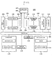
- the biological light measurement device of the present invention is a device that irradiates near-infrared light into the body, detects light reflected from the vicinity of the surface of the body or transmitted through the body (hereinafter, simply referred to as transmitted light), and generates an electric signal corresponding to the intensity of the light.
- this biological light measurement device 100 includes a light source unit 101 that irradiates near-infrared light, a light measurement unit 102 that measures transmitted light and converts it into an electric signal, and a control unit 103 that controls driving of the light source unit 101 and the light measurement unit 102.
- the light source unit 101 includes a semiconductor laser 104, which emits light with a predetermined wavelength, and a plurality of optical modules 105, which have a modulator for modulating the light generated by the semiconductor laser 104 to have a plurality of different frequencies.
- Output light of each optical module 105 is irradiated from a predetermined measurement region of a subject body 107, for example, a plurality of places of the head through an optical fiber 106.
- a probe holder 108 is fixed to the subject body 107, and the optical fiber 106 and an optical fiber for detection 109 are fixed to the probe holder 108.
- an approximate midpoint of the light irradiation position of the optical fiber 106 and the light detection position of the optical fiber for detection 109 in the probe holder 108 is defined as a measurement channel.
- the probe holder 108 has light irradiation positions and light detection positions, which are arrayed in a square matrix with predetermined distances therebetween according to the head shape of the subject body 107, and calculates a concentration change of oxygenated hemoglobin, a concentration change of deoxygenated hemoglobin, and a change in the total hemoglobin concentration when the brain of the subject body 107 is not stimulated and when the brain is stimulated in the measurement position (measurement channel) which is a middle position of the light irradiation position and the light detection position adjacent to each other.
- the light measurement unit 102 includes a photoelectric conversion element 110 such as a photodiode which converts each transmitted light beam, which is guided from a plurality of measurement places of the measurement region through the optical fiber for detection 109, into the amount of electricity corresponding to the amount of light, a lock-in amplifier 111 to which an electric signal from the photoelectric conversion element 110 is input and which selectively detects a modulation signal corresponding to the light irradiation position, and an A/D converter 112 which converts an output signal of the lock-in amplifier 111 into a digital signal.
- a photoelectric conversion element 110 such as a photodiode which converts each transmitted light beam, which is guided from a plurality of measurement places of the measurement region through the optical fiber for detection 109, into the amount of electricity corresponding to the amount of light
- a lock-in amplifier 111 to which an electric signal from the photoelectric conversion element 110 is input and which selectively detects a modulation signal corresponding to the light irradiation position
- the light source unit 101 includes "n" optical modules (n is a natural number). Although the wavelength of light depends on the spectral characteristic of an observed matter inside the body, one or a plurality of wavelengths are selected and used from light in a wavelength range of 600 nm to 1400 nm in the case of measuring the oxygen saturation or the amount of blood from the concentration of Hb and HbO 2 .
- the light source unit 101 is configured to generate light beams with two kinds of wavelengths, for example, wavelengths of 780 nm and 830 nm corresponding to two kinds of objects to be measured of oxygenated hemoglobin and deoxygenated hemoglobin, and the light beams with these two wavelengths are mixed and irradiated from one radiation position.
- the lock-in amplifier 111 selectively detects a modulation signal corresponding to the light irradiation position and these two wavelengths. Hemoglobin amount change signals corresponding to the number of channels, which is twice the number of points (measurement points) between the light irradiation positions and the detection positions, are acquired.
- a signal processing unit 113 a storage unit 115, and an input/output unit 116 including a display unit 114 or a mouse 117 are further connected to the control unit 103.
- a stimulus presenting unit 118 is provided near the subject body 107 so that a predetermined stimulus generated by the control unit 103 or the like is presented (displayed) on the subject body 107.
- the storage unit 115 stores data necessary for processing of the signal processing unit 113 or a processing result.
- data regarding the head shape for display for example, a plurality of "standard patterns of the head shape" for display corresponding to the age or sex of the subject body 107 is set as a table in a form, in which data of a two-dimensional plane figure and data of a three-dimensional shape (wireframe image) form a pair, and is stored in the storage unit 115.
- a standard pattern of the head shape or the shape of a probe is prepared beforehand as the positional information enough for a measuring person (user) to understand a specific measured part of a subject body, for example, measurement positions such as the frontal and occipital regions, according to measurement purposes of the subject body 107, on the basis of the past data examples of biological light measurement.
- data regarding the head shape for display data of each shape of a plurality of probe holders provided in the biological light measurement device or data of positional relationship of an optical fiber or an optical fiber for detection in each probe holder is formed as a set and formed as a table as data of a "probe" having a predetermined pattern and is stored in the storage unit 115.
- the control unit 103 or the signal processing unit 113 has various kinds of arithmetic processing functions or image processing display functions realized by a CPU, a memory, software, and the like.
- arithmetic processing function for example, a change signal of the amount of hemoglobin converted into a digital signal is processed.
- the signal processing unit 113 On the basis of the processed information, the signal processing unit 113 generates a graph showing a concentration change of oxygenated hemoglobin, a concentration change of deoxygenated hemoglobin, a change in the total hemoglobin concentration, and the like for every channel or an image obtained by plotting them on the two-dimensional image of the subject body.
- a processing result of the signal processing unit 113 is displayed on the display unit 114 of the input/output unit 116.
- the input/output unit 116 has a function for inputting various instructions required for an operation of the device or outputting a measurement result or a processing result by the measuring person.
- a display screen of the display unit 114 has a graphical user interface (GUI) function, and it functions as an input unit used when a user inputs instructions required for various kinds of measurements or processing or information, such as the coordinate information, by operating an icon, a "probe" position, and the like on the display screen with the mouse 117 or the like.
- GUI graphical user interface
- the display unit 114 for the input of two-dimensional position coordinates of the "probe” and a display unit, which displays a processing result of the signal processing unit 113 so as to overlap the position of a head shaped probe may be separately provided when necessary.
- Fig. 2 shows a main function of the control unit 103, the display unit 114, or the like in the biological light measurement device 100 of the present invention.
- the display unit 114 of the biological light measurement device 100 includes: a head shape data selecting section 201 for making a user select a "standard pattern of the head shape” or a "probe", which is optimal for a subject body, from the data of the storage unit 115, such as the "standard head shape”; a probe position easy-input section 202 for generation based on the selected standard pattern of the head shape and the like and for making the user input and set the probe position of the subject body on the screen image of the displayed "head shape”; and a display section 209 that displays a coordinate-converted image, the light irradiation position and the light detection position on the head shape, or an image in which a topographic image overlaps the calculation position of a measurement channel.
- the control unit 103 of the biological light measurement device 100 includes: a coordinate transformation section 203 that calculates the light irradiation position and the light detection position or the position of a measurement channel on a three-dimensional head image by performing coordinate transformation processing of the input probe position; a stimulus presenting section 206 that presents a stimulus to the subject body; a topographic image generating section 207 which generates a topographic image on the basis of the light irradiation position; and an overlap processing section 208 that generates a topographic image, on the basis of the input probe position, so as to overlap the light irradiation position and the light detection position on the head shape or the calculation position of a measurement channel.
- the coordinate transformation section 203 has a function of calculating the light irradiation position and the light detection position on the three-dimensional head image or the position of a measurement channel according to the two-dimensional position information set by the probe position easy-input section 202.
- the coordinate transformation section 203 includes a two-dimensional coordinate to three-dimensional coordinate transformation section 204, which performs transformation from two-dimensional coordinates to three-dimensional coordinates, and a three-dimensional coordinate to two-dimensional coordinate transformation section 205, which performs transformation from three-dimensional coordinates to two-dimensional coordinates.
- the coordinate transformation section 203 calculates the light irradiation position and the light detection position or the calculation position of a measurement channel by sequentially repeating the coordinate transformation processing between the shapes approximated on the way from the two-dimensional head image to the three-dimensional head image.
- the coordinate transformation section 203 can perform both two-dimensional display and three-dimensional display of a probe position so that the user information can be input or an operation result can be output and displayed.
- the above-described main functions that the biological light measurement device 100 of the present invention have are realized by all of the control unit 103, the display unit 114, and the like using software, and it is needless to say that they are not limited to the block configuration shown in Fig. 2 .
- the biological light measurement device 100 of the present invention has a function of easily displaying and setting the light irradiation position and the light detection position or the three-dimensional position of a measurement channel using a display unit with a GUI function. That is, it is possible to realize a function of easily setting the light irradiation position and the light detection position of a subject body on the two-dimensional head image of the display screen, estimating the light irradiation position and the light detection position on the three-dimensional head image by arithmetic processing, such as coordinate transformation, based on the information set in this way, and displaying the actually measured topographic image at the calculation position on the head image obtained by arithmetic processing so as to overlap each other, without measuring the actual light irradiation position and light detection position set in the subject body after a measuring person mounts the probe holder 108 at the head of the subject body 107. Accordingly, since time and effort when measuring the actual light irradiation position and light detection position set in the subject body at the time of biological
- a user selects a "standard pattern of the head shape” or a "probe", which is optimal for a subject body, using a display screen by the head shape data selecting section 201.
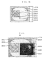
- Fig. 4 ( Figs. 4A , 4B , and 4C ) shows an example of the display screen in the present invention.
- an operation screen 2011 which gives a priority to ease of an operation is assumed. That is, the operation screen 2011 shown in Fig. 4A is displayed on the display screen of the display unit 114.
- a light irradiation position and a light detection position or a measurement channel that is, a two-dimensional head image 2012, one probe (two-dimensional probe) 2013 in which a plurality of light irradiation positions and a plurality of light detection positions are set as one group as a whole, a center coordinate position 2014 of a two-dimensional probe, and a center coordinate position 2015 of a two-dimensional head image are displayed on this operation screen 2011.
- 2019 is an operation input unit in which input columns of various kinds of instructions or data and icons, such as pull down type operation buttons, are disposed.
- a user may arbitrarily select or change and display the shapes, positions, and sizes of the two-dimensional head image 2012 and the two-dimensional probe 2013 on the operation screen 2011 according to the age of the subject body 107, measurement purposes, type of the probe holder 108 to be used, and the like by mouse operation or the like.
- the two-dimensional head image 2012 shown in Fig. 4A is a plane image when the head is viewed from above.
- a plurality of light irradiation positions and a plurality of light detection positions are regularly arrayed in one square probe corresponding to the shape of the probe holder 108 used, and the probe center is present at the center of the figure.
- distances between the light irradiation positions or the light detection positions may be set to be unequal by the installation position of the probe holder 108 so as to correspond to the top view of the probe holder 108 in a state mounted on the head, and the central position of the figure may also be shifted within the probe so that it is displayed on the two-dimensional head image.
- two-dimensional head image it is also possible to form a database so that images when the head is viewed from various directions according to measurement purposes, for example, two-dimensional head images of left and right temporal parts, the front, or the back of the head can be selected as two-dimensional images for positioning by the user.
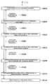
- the user sets the position of the probe 2013 on the selected two-dimensional head image 2012 on the software (S2010).
- a measuring person calculates a light irradiation position and a light detection position on the three-dimensional head image using the setting position information regarding the probe position on the two-dimensional head image set by a simple operation (S2110).
- the user performs coordinate transformation processing on the basis of the position of the probe 2013 on the two-dimensional head image set on the software.
- coordinate transformation processing coordinate transformation processing between the shapes approximated on the way from the two-dimensional head image to the three-dimensional head image is executed while being sequentially repeated, and the light irradiation position and the light detection position or the calculation position of a measurement channel is calculated. That is, by performing coordinate transformation processing A (S2020), coordinate transformation processing B (S2040), and coordinate transformation processing C (S2060) regarding the position of the probe center, the position of the probe center on the three-dimensional semi-ellipsoidal surface is calculated (S2060).
- processing of calculating the length of an ellipse arc and processing of calculating a light irradiation position and a light detection position from the coordinate position of the probe center on the three-dimensional semi-ellipsoidal surface are executed (S2080).
- a light irradiation position and a light detection position on the three-dimensional head image or a measurement channel that is, a light irradiation position and a light detection position are further calculated (S2110).
- types of the shape approximated on the way or the number of times of coordinate transformation processing is not limited to the example described above.
- the intermediate coordinate transformation processing C (S2060) described above may be omitted.
- a three-dimensional hemispherical image instead of the three-dimensional head image, as a final image by performing the coordinate transformation processing B and C on a two-dimensional head image and to calculate a light irradiation position, a light detection position, or a measurement channel from the coordinate position of the probe center on the three-dimensional hemispherical image.
- a three-dimensional head image (wireframe image) 3100 may be displayed simultaneously on the operation screen 2011 so as to overlap the two-dimensional head image 2012. This is based on a result in which a result of calculation processing is immediately reflected on the operation screen since the two-dimensional shape data and the three-dimensional shape data are set as a table as a pair and stored in a storage device or on the basis of a bidirectional processing function of coordinate transformation between two dimensions and three dimensions, which will be described in detail later.
- a shape frame image of the head of a subj ect body is used in the present embodiment.
- numeric values in circles and rectangular corners within the two-dimensional probe 2013 indicate irradiation positions and light detection positions in the left head of the subject body.
- the three-dimensional head image 3100 is displayed in a three-dimensional probe 2017.
- the position of a three-dimensional probe 2018 in the three-dimensional head image 3100 is a left head corresponding to the position of the two-dimensional probe 2013 in the two-dimensional head image 2012.
- Fig. 4C shows a state where a horizontally long rectangle is selected as a shape of the two-dimensional probe 2013 by a mouse operation and the position is also in a frontal part. At this time, the position of the three-dimensional probe 2018 in the three-dimensional head image 3100 is also in the frontal part.
- the bidirectional processing function of coordinate transformation processing the user can change the shape and position of the three-dimensional probe 2018 by a mouse operation or the like. Accordingly, it is possible to change the shape and position of the two-dimensional head image 2012.
- the position of a two-dimensional probe in a two-dimensional head image is in cooperation changed, moved, and displayed.
- a measuring person may operate the three-dimensional probe 2018 on the three-dimensional head image by a simple operation using a mouse or the like and input the three-dimensional position coordinates of the probe holder 108.
- a user sets the probe position 2010 on the two-dimensional head image 2012, which is displayed on the operation screen 2011 of Fig. 4A , by a mouse operation or the like.
- the case is assumed in which the two-dimensional head image 2012 is used to show the approximate positions of the light irradiation position and the light detection position and the accuracy of the positional information of the light irradiation position and the light detection position on the two-dimensional head image 2012 is low accordingly.
- the center coordinate position 2014 of a probe on the two-dimensional head image is used as setting position information of the user on the two-dimensional head image 2012.
- coordinate transformation processing A (S2020) is performed to calculate a coordinate position 2031 of the probe center on a two-dimensional circle image 2032, which is shown in Fig. 5 , from the center coordinate position 2014 of the probe on the two-dimensional head image 2012 (S2030).
- the center of the two-dimensional circle image 2032 matches the center coordinate position 2015 of the two-dimensional head image.
- coordinate transformation processing B (S2040) is performed to calculate a coordinate position 2051 of the probe center on a three-dimensional hemispherical surface 2052, which is shown in Fig. 6 , from the coordinate position 2031 of the probe center on the two-dimensional circle image 2012 (S2050).
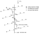
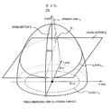
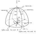
- coordinate transformation processing C (S2060) is performed to calculate a coordinate position 2071 of the probe center on a three-dimensional semi-ellipsoidal surface 2072, which is shown in Fig. 7 , from the coordinate position 2051 of the probe center on the three-dimensional hemispherical surface (S2070).
- a light irradiation position and light detection position 2091 on the three-dimensional semi-ellipsoidal surface 2072 shown in Fig. 8 is calculated from the coordinate position 2071 of the probe center on the three-dimensional semi-ellipsoidal surface (S2090). Details of the calculation processing A (S2080) will be described later.
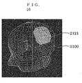
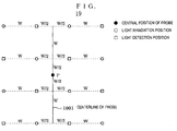
- a light irradiation position and light detection position 2111 on the three-dimensional head image 3100 shown in Fig. 9 is calculated from a light irradiation position and light detection position 2090 on the three-dimensional semi-ellipsoidal surface (S2110).
- Calculating the position on the three-dimensional semi-ellipsoidal surface 2072 in the course of coordinate transformation is performed because the three-dimensional shape of the three-dimensional semi-ellipsoidal surface 2072 is closer to the three-dimensional shape of the three-dimensional head image 3100 than to that of the three-dimensional hemispherical surface 2052 and accordingly, there is an advantage in that processing of coordinate transformation becomes easy.
- a body transmitted light intensity image 2121 and a shape image of an object to be measured as an indication of a measured part are displayed so as to overlap each other on three dimensions, as shown in Fig. 10 (S2120).
- the topographic image generating section 207 based on the light irradiation position calculates a distance d between a light irradiation position and a light detection position, which are adjacent to each other, in a three-dimensional space from the read light irradiation position and light detection position 2111 for every measurement position.
- the number of measurement positions is 16. Accordingly, the number of distances d between light irradiation positions and light detection positions in the three dimensional space calculated by the calculation is 24.
- the topographic image generating section 207 corrects a topographic image Hb data (original), which is based on the two-dimensional light irradiation position and light detection position that are topographic images before correction, according to the following expression (1), and generates a topographic image Hb data (new) based on the three-dimensional light irradiation position and light detection position that are topographic images after correction.
- the pixel value of each pixel of a topographic image obtained by cubic spline interpolation is corrected by the distance d of a measurement position closest to the pixel.
- the correction at this time is based on the following expression (1).
- the topographic image generating section 207 converts the topographic image after correction into a topographic image according to the wireframe image generated previously. Specifically, the topographic image generating section 207 converts the topographic image after correction into a three-dimensional topographic image by performing three-dimensional mapping interpolation of the pixel value of each pixel, which forms a topographic image, so as to match head wireframe coordinates.
- the topographic image generating section 207 generates a three-dimensional image in which a topographic image overlaps a wireframe image, converts the three-dimensional image into a two-dimensional image ("three-dimensional topographic image") seen from the viewing position instructed from an input means, and displays it on the display surface of the display means.
- the coordinate transformation processing A (S2020), the coordinate transformation processing B (S2040), the coordinate transformation processing C (S2060), and the coordinate transformation processing D (S2100) are reversible coordinate transformation processing. Therefore, it is also possible to calculate and display the probe position on a two-dimensional head image by setting the probe position on a three-dimensional head image on the three-dimensional head image by the user.
- a user sets the probe position 2017 on the three-dimensional head image on the software.
- the position equivalent to the central point of the probe 2111 on the three-dimensional head image 3100, which is shown in Fig. 9 is assumed to be set.
- the coordinate position 2071 of the probe center on the three-dimensional semi-ellipsoidal surface 2072 shown in Fig. 7 is calculated from the probe center on the three-dimensional head image.
- the coordinate position 2051 of the probe center on the three-dimensional hemispherical surface 2052 shown in Fig. 6 is calculated from a coordinate position 2070 of the probe center on the three-dimensional semi-ellipsoidal surface.
- the coordinate position 2031 of the probe center on the two-dimensional circle image 2032 shown in Fig. 5 is calculated from the coordinate position 2051 of the probe center on the three-dimensional hemispherical surface.
- the coordinate transformation processing B (S2020) the position of the probe 2013 on the two-dimensional head image is calculated from the coordinate position 2031 of the probe center on this two-dimensional circle image.
- the light irradiation position and light detection position 2091 on the three-dimensional semi-ellipsoidal surface 2072 and the light irradiation position and light detection position 2111 on the three-dimensional head image 3100 are calculated from the coordinate position 2071 of the probe center on the three-dimensional semi-ellipsoidal surface 2072.
- a body transmitted light intensity image and a shape image of an object to be measured as an indication of a measured part can be displayed so as to overlap each other on three dimensions, without measuring the three-dimensional coordinates of the light irradiation position and the light detection position, by realizing a function in which a measuring person sets a light irradiation position and a light detection position on the head image displayed on two dimensions and calculates a light irradiation position and a light detection position on three dimensions according to the set information.
- a body transmitted light intensity image of the subject body and a shape image of an object to be measured as an indication of a measured part can be displayed so as to overlap each other on the three-dimensional image. Since an accurate measurement result of the light irradiation position and the light detection position is not needed, a time of the whole biological light measurement can be shortened by omission of position measurement, and the cost and a burden on a measuring person can be reduced.
- the calculation procedure of making a point on a two-dimensional head image uniquely correspond to a point on a two-dimensional circle image by the coordinate transformation processing A (S2020) will be described.
- the two-dimensional circle image is assumed to be a circle with a radius Rc and the central point (0 0).
- the coordinate transformation processing B (S2040) will be described using Fig. 12 .
- the two-dimensional circle image is a circle with a radius Rc and a central point (0 0) and the three-dimensional hemispherical surface is a hemispherical surface with a radius Rs and a central point (0 0 0).
- the three-dimensional hemispherical surface is a hemispherical surface with a radius Rs and a central point (000). It is assumed that the three-dimensional semi-ellipsoidal surface is a semi-ellipsoidal surface with radii Rvx, Rvy, and Rvz and a central point (0 0 0).
- the calculation procedure of making a point on a three-dimensional semi-ellipsoidal surface uniquely correspond to a point on a three-dimensional hemispherical surface by the coordinate transformation processing C (S2060) will be described. It is assumed that the three-dimensional semi-ellipsoidal surface is a semi-ellipsoidal surface with radii Rvx, Rvy, and Rvz and a central point (0 0 0). It is assumed that the three-dimensional hemispherical surface is a hemispherical surface with a radius Rs and a central point (0 0 0). Each coordinate point is expressed as follows.
- Point Pv(Xv Yv Zv) point on a three-dimensional semi-ellipsoidal surface to be subjected to coordinate transformation processing C
- Point Ps(Xs Ys Zs) point on a three-dimensional hemispherical surface after coordinate transformation of the point Pv by the coordinate transformation processing C
- the calculation of coordinate transformation is performed as follows.
- Xs Ys Zs Rs Rvx ⁇ Xv Rs Rvy ⁇ Yv Rs Rvz ⁇ Zv
- the coordinate transformation processing D (S2100) will be described using Fig. 14 .
- a point on a three-dimensional semi-ellipsoidal surface is made to uniquely correspond to a point on a three-dimensional head image by the coordinate transformation processing D (S2100). It is assumed that the three-dimensional semi-ellipsoidal surface is a semi-ellipsoidal surface with radii Rvx, Rvy, and Rvz and a central point (0 0 0). It is assumed that the three-dimensional head image is formed by N polygons and its central point is (0 0 0). Although this calculation processing does not depend on the shape of a polygon, it is assumed that the three-dimensional head image is formed by triangle polygons in the present embodiment.
- Each coordinate point is expressed as follows.
- a point on a three-dimensional head image is made to uniquely correspond to a point on a three-dimensional semi-ellipsoidal surface by the coordinate transformation processing D (S2100). It is assumed that the three-dimensional semi-ellipsoidal surface is a semi-ellipsoidal surface with radii Rvx, Rvy, and Rvz and a central point (0 0 0). It is assumed that the central point of a three-dimensional head image is (0 0 0). Each coordinate point is expressed as follows.
- a three-dimensional head image is approximated using a three-dimensional semi-ellipsoid.
- three radii Rvx, Rvy, and Rvz of a three-dimensional semi-ellipsoid are simply calculated from a three-dimensional head image in the present embodiment.
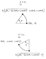
- the procedure of calculating three radii of a three-dimensional semi-ellipsoid using four points of a right ear P h.R , a left ear P h.L , the Nasion P h.N , and the crown P h.T in a three-dimensional head image will be described using Fig. 16.
- FIG. 16 is a view showing calculation processing of approximating a three-dimensional head image to a three-dimensional semi-ellipsoid.
- the midpoint O h of the right ear P h.R and the left ear P h.L is found, and O h P hR is set as Rvx.
- a perpendicular is drawn from Nasion P h.N to the straight line P h.R P h.L , a distance between a point of the foot and P h.N , and it is set as Rvy.
- a perpendicular is drawn from the crown P h.T to the plane including the midpoint O h of the right ear P h.R and the left ear P h.L , a distance between a point of the foot and P h.T , and it is set as Rvz.
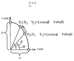
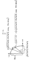
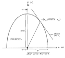
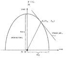
- Fig. 17 is a view showing an example of calculating the length of an ellipse arc.
- the problem of finding the length of an ellipse arc is known as a problem of calculating an elliptic integral. Since it cannot be calculated by an elementary function, it can be approximately calculated by numerical integration. Although several methods are proposed as numerical integration, the calculation is performed by mensuration by parts using the extended midpoint rule in the present embodiment.
- the radii of an ellipse are set to a and b and its center is set (0, 0), and the length L of an arc between two points P 1 (X 1 Y 1 ) and P 2 (X 2 Y 2 ) on the ellipse is calculated.
- ⁇ ⁇ ⁇ is assumed because the universalness is satisfied even if ⁇ ⁇ ⁇ .
- the length L of the arc of the ellipse is expressed by the following definite integral.
- a method of calculating the point coordinates which are away from a certain point on an ellipse by a designated distance will be described on the basis of Fig. 17 .
- the coordinates of the point P 2 at which the distance on the ellipse to the point P 1 is L are calculated.
- the point P 1 is expressed as follows using ⁇ .
- P 1 X 1 Y 1 acos ⁇ bsin ⁇
- the point P 2 is expressed as follows using the angle of deflection ⁇ .
- P 2 X 2 Y 2 acos ⁇ bsin ⁇
- the angle of deflection P is calculated.
- ⁇ ⁇ ⁇ and a ⁇ b are assumed because the universalness is satisfied even if ⁇ ⁇ P and a ⁇ b.
- the length of an ellipse arc is calculated for the candidate value of the angle of deflection ⁇ in a possible range and the angle of deflection which is closest to the designated distance is adopted. Specifically, the calculation is performed as follows.
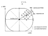
- Fig. 18 is a view explaining an example of setting the probe position on a two-dimensional head image
- Fig. 19 is a view explaining the shape information (before rotation) regarding a probe on a two-dimensional plane
- Fig. 20 is a view explaining the shape information (after rotation) regarding a probe on a two-dimensional plane.
- a light irradiation position and a light detection position on a three-dimensional semi-ellipsoidal surface are calculated from the coordinate position of the probe center on the three-dimensional semi-ellipsoidal surface.
- a probe on a two-dimensional head image is disposed as shown in Fig. 18 , for example.
- the inclination of a reference line (901) which connects the central point of a probe and the central point of a two-dimensional head image is set to ⁇ u
- the inclination of a centerline (902) of the probe with respect to the reference line (901) is set to ⁇ u .
- the information regarding the relationship between the probe center and the light irradiation position and the light detection position in the probe is used as known probe shape information.
- the probe shape information it is usually preferable to assume a sheet-like probe, in which a certain fixed number of light irradiation positions and light detection positions are mixed together, and to use the shape information.
- each light irradiation position and each light detection position are arrayed on the sheet shape on the two-dimensional plane as the probe shape information.
- the shape information shown in Fig. 19 is used as the probe shape information. All distances between the light irradiation positions and the light detection positions were set to W.
- the coordinates of the central position of the probe on the two-dimensional plane is set to (0 0).
- the coordinate points of N light irradiation positions and N light detection positions on the two-dimensional plane are set to M 1 (x 1 y 1 ), ⁇ ⁇ ⁇ , M i (x i y i ) ⁇ ⁇ ⁇ , M N (x N y N ).
- the coordinate points of the N light irradiation positions and the N light detection positions on the two-dimensional plane are as follows, as shown in Fig. 20 .
- Each foot of the perpendiculars is set as a reference point.
- a distance (expression 2) from the center of a probe to a reference point and a distance (expression 3) from the reference point to each light irradiation position and each light detection position are used from the shape information of the probe.
- P ⁇ K 1 , ⁇ P ⁇ K i ⁇ , P ⁇ K N K 1 ⁇ M 1 , ⁇ K i ⁇ M i ⁇ , K N ⁇ M N In order to calculate the position of M i on the three-dimensional semi-ellipsoid, the following two steps of calculation are performed.
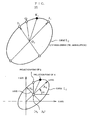
- Fig. 21 is a view explaining the calculation (three-dimensional semi-ellipsoid) of the coordinate position of a reference point
- Fig. 22 is a view explaining the calculation (cut ellipsoid S1) of the coordinate position of a reference point.
- the angle ⁇ between the Xv axis and a line segment, which is obtained by projecting the reference line to the XvYv coordinate plane, is calculated as follows.
- the point M i is calculated as a point, at which the distance from the reference point K i becomes (expression 5), on the curve (curve L 2 ) formed as a line of intersection of an ellipsoid and a cross section (cross section S 2 ) which is perpendicular to the "tangential plane at the point K i on the ellipsoid” and which is perpendicular to the "cross section (cross section S 1 ) perpendicular to the bottom surface of the ellipsoid passing through the point K i ".
- the calculation procedure is as follows.
- the cross section S 2 is calculated as follows.
- Cross section S 2 X - X Ki + h 2 ⁇ Y - Y Ki - h 3 ⁇ Z - Z Ki 0
- h 2 tan ⁇
- h 3 Rvz Rvx ⁇ 1 cos ⁇ v ⁇ tan ⁇ Ki
- the expression of the ellipsoid becomes as follows.
- X 2 Rvx 2 + Y 2 Rvy 2 + Z 2 Rvz 2 1
- Z X - X Ki h 3 + h 2 ⁇ Y - Y Ki h 3 + Z Ki
- This expression of the cross section S 2 is substituted into the expression of the ellipsoid to find a cross-sectional line formed by the line of intersection of the cross section S 2 and the ellipsoid.
- Fig. 25 is a view showing the relationship between the curve L2 on the three-dimensional semi-ellipsoid and the curve L3 on the XY plane in the condition 1.
- the cross section S 2 is calculated as follows.
- Cross section S 2 (X - X Ki ) - h 3 (Z - Z Ki ) 0
- h 3 Rv ⁇ z 2 ⁇ X Ki Rv ⁇ x 2 ⁇ Z Ki
- the following expression is obtained by changing the expression of the cross section S 2 .
- Z X - X Ki + h 3 ⁇ Z Ki h 3
- the expression of the cross section S 2 is substituted into the expression of the ellipsoid to find a cross-sectional line formed by the line of intersection of the cross section S 2 and the ellipsoid.
- the cross section S 2 is calculated as follows.
- Cross section S 2 Y - Y Ki - h 3 ⁇ Z - Z Ki 0
- h 3 Rv ⁇ z 2 ⁇ Y Ki Rv ⁇ y 2 ⁇ Z Ki
- the expression of the ellipsoid is as follows.
- X 2 Rv ⁇ x 2 + Y 2 Rv ⁇ y 2 + Z 2 Rv ⁇ z 2 1
- the following expression is obtained by changing the expression of the cross section S 2 .
- Z Y - Y Ki + h 3 ⁇ Z Ki h 3
- a cross-sectional line formed as a line of intersection of the cross section S 2 and the ellipsoid is calculated.
- the solution can be approximately calculated by mensuration by parts using the extended midpoint rule.
- the calculation is performed as follows using an appropriate division number N.
- the curve L 2 is an ellipse with radii of Rv ⁇ x 2 ⁇ cos 2 ⁇ ⁇ 2 + Rv ⁇ y 2 sin 2 ⁇ ⁇ 2 and Rvz on the cross section S 2 .
- the expression of the curve L 2 is as follows.
- X c 2 Rv ⁇ x 2 cos 2 ⁇ 2 + Rv ⁇ y 2 sin 2 ⁇ 2 + Y c 2 Rv ⁇ z 2 1
- the coordinates of the point Q on the curve L 2 is expressed as follows using the angle of deflection ⁇ c .
- Point Q on the curve L 2 Rv ⁇ x 2 cos 2 ⁇ 2 + Rv ⁇ y 2 sin 2 ⁇ 2 cos ⁇ c Rvz ⁇ sin ⁇ c
- the radius of a three-dimensional sphere is set to Rs.
- the central point of a probe is set to P (Rs 0 0) .
- P Rs 0 0
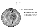
- a light irradiation position and a light detection position are disposed on the three-dimensional spherical surface with the x axis on three dimensions as the center.
- the coordinate points of light irradiation positions and light detection positions of N points on three dimensions are set to M 1 (x 1 y 1 z 1 ) , ⁇ ⁇ ⁇ , M i (x i y i z i ) ⁇ ⁇ ⁇ , M N (x N y N z N ).
- the rotation is assumed to be performed with the x axis on three dimensions as the center. (refer to Fig. 36 )
- the coordinate points of light irradiation positions and light detection positions of N points on three dimensions are set as follows, as shown in Fig. 36 .
- a point which becomes the foot onto the reference point of the probe is calculated.
- These are set as reference points K 1 , ⁇ ⁇ ⁇ K i , ⁇ ⁇ ⁇ , K N with respect to each point of the light irradiation position and the light detection position.
- the reference point K i is calculated as follows. K i ⁇ R S 2 - y i sin ⁇ u + z i cos ⁇ u 2 0 y i sin ⁇ u + z i cos ⁇ u
- an arc length (expression 2) between the central point of the probe and each reference point and an arc length (expression 3) between each reference point and each point of the light irradiation position and the light detection position are calculated.
- (expression 4) and (expression 5) found for M i and the reference point K i are as follows.
- the coordinate positions of the light irradiation position and the light detection position on the three-dimensional elliptical hemisphere can be calculated, similar to the case where the shape on the two-dimensional plane is used.
- Fig. 39 shows a flow chart of the display function of the electroencephalographic electrode position.
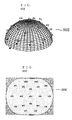
- a 10-20 electrode arrangement method is generally known. Details of the 10-20 electrode arrangement method are disclosed, for example, in Non-patent Document 1 ( new clinical examination technician lecture 7, clinical physiology (third edition), Igaku-Shoin Ltd. , pp. 174-176 ) and the like. In the present embodiment, this 10-20 electrode arrangement method is used. According to the defined arrangement method, the coordinate position (301) of each electrode on the three-dimensional hemisphere is calculated. The calculated result is like 302 of Fig. 40A .
- the coordinate position (303) of each electrode on a two-dimensional circle image can be obtained by performing the coordinate transformation processing B (S2040) on the coordinate position (301) of each electrode on the three-dimensional hemisphere.
- the coordinate position (305) of each electrode on a two-dimensional head image can be obtained by performing the coordinate transformation processing A (S2020) on the coordinate position (303) of each electrode on the two-dimensional circle image.
- an overlap image (306) with the two-dimensional head image 2012 can be obtained and presented as shown in Fig. 40B .
- the coordinate position (307) of each electrode on a three-dimensional semi-ellipsoid can be obtained by performing the coordinate transformation processing C (S2060) on the coordinate position (301) of each electrode on the three-dimensional hemisphere.
- the coordinate position (308) of each electrode on a three-dimensional head image 3100 can be obtained by performing the coordinate transformation processing D (S2080) on the coordinate position (307) of each electrode on the three-dimensional semi-ellipsoid.
- an overlap image (310) with the shape head can be obtained and presented as shown in Fig. 40C .
- the three-dimensional head image the three-dimensional semi-ellipsoidal image, the three-dimensional hemispherical image, the two-dimensional circle image, and the two-dimensional head image
Landscapes
- Health & Medical Sciences (AREA)
- Life Sciences & Earth Sciences (AREA)
- Physics & Mathematics (AREA)
- Surgery (AREA)
- General Health & Medical Sciences (AREA)
- Engineering & Computer Science (AREA)
- Biomedical Technology (AREA)
- Heart & Thoracic Surgery (AREA)
- Medical Informatics (AREA)
- Molecular Biology (AREA)
- Biophysics (AREA)
- Animal Behavior & Ethology (AREA)
- Pathology (AREA)
- Public Health (AREA)
- Veterinary Medicine (AREA)
- Neurology (AREA)
- Spectroscopy & Molecular Physics (AREA)
- Optics & Photonics (AREA)
- Measurement Of The Respiration, Hearing Ability, Form, And Blood Characteristics Of Living Organisms (AREA)
- Length Measuring Devices By Optical Means (AREA)
- Investigating Or Analysing Materials By Optical Means (AREA)
- Image Processing (AREA)
Applications Claiming Priority (2)
| Application Number | Priority Date | Filing Date | Title |
|---|---|---|---|
| JP2008256510 | 2008-10-01 | ||
| PCT/JP2009/067023 WO2010038774A1 (fr) | 2008-10-01 | 2009-09-30 | Dispositif de mesure d’une lumière biologique et procédé d’affichage de position pour afficher une position d’irradiation de lumière et une position de détection de lumière, ou canal de mesure |
Publications (2)
| Publication Number | Publication Date |
|---|---|
| EP2335580A1 true EP2335580A1 (fr) | 2011-06-22 |
| EP2335580A4 EP2335580A4 (fr) | 2015-03-04 |
Family
ID=42073534
Family Applications (1)
| Application Number | Title | Priority Date | Filing Date |
|---|---|---|---|
| EP09817806.4A Withdrawn EP2335580A4 (fr) | 2008-10-01 | 2009-09-30 | Dispositif de mesure d'une lumière biologique et procédé d'affichage de position pour afficher une position d'irradiation de lumière et une position de détection de lumière, ou canal de mesure |
Country Status (5)
| Country | Link |
|---|---|
| US (1) | US8565501B2 (fr) |
| EP (1) | EP2335580A4 (fr) |
| JP (1) | JP5159893B2 (fr) |
| CN (1) | CN102170826B (fr) |
| WO (1) | WO2010038774A1 (fr) |
Families Citing this family (7)
| Publication number | Priority date | Publication date | Assignee | Title |
|---|---|---|---|---|
| KR101661934B1 (ko) * | 2010-07-29 | 2016-10-04 | 삼성전자주식회사 | 영상 처리 장치 및 방법 |
| JP2014030621A (ja) * | 2012-08-03 | 2014-02-20 | Sony Corp | 情報処理装置、プログラム及び生体信号測定セット |
| US20150342461A1 (en) * | 2012-11-14 | 2015-12-03 | Shimadzu Corporation | Optical biometric device and position measuring device used therein |
| US9091628B2 (en) | 2012-12-21 | 2015-07-28 | L-3 Communications Security And Detection Systems, Inc. | 3D mapping with two orthogonal imaging views |
| JP7415856B2 (ja) | 2020-09-02 | 2024-01-17 | 株式会社デンソーウェーブ | 物体認識装置、物体認識方法及びプログラム |
| CN114246556B (zh) * | 2022-03-01 | 2022-05-24 | 慧创科仪(北京)科技有限公司 | 用于近红外脑功能成像装置的定位方法、设备和存储介质 |
| CN114246557A (zh) * | 2022-03-01 | 2022-03-29 | 慧创科仪(北京)科技有限公司 | 用于近红外脑功能成像装置的定位方法、设备及存储介质 |
Family Cites Families (20)
| Publication number | Priority date | Publication date | Assignee | Title |
|---|---|---|---|---|
| US5803909A (en) * | 1994-10-06 | 1998-09-08 | Hitachi, Ltd. | Optical system for measuring metabolism in a body and imaging method |
| JP3599426B2 (ja) * | 1995-07-05 | 2004-12-08 | 株式会社日立製作所 | 生体光計測装置 |
| US6240309B1 (en) * | 1995-10-06 | 2001-05-29 | Hitachi, Ltd. | Optical measurement instrument for living body |
| US20060184047A1 (en) * | 1995-11-17 | 2006-08-17 | Yuichi Yamashita | Optical measurement instrument for living body |
| JP4006826B2 (ja) * | 1998-04-28 | 2007-11-14 | 株式会社日立製作所 | 生体光計測装置 |
| JP4076003B2 (ja) * | 1999-02-19 | 2008-04-16 | 株式会社日立製作所 | 生体光計測装置 |
| US7228166B1 (en) * | 1999-09-14 | 2007-06-05 | Hitachi Medical Corporation | Biological light measuring instrument |
| JP4266453B2 (ja) * | 1999-09-14 | 2009-05-20 | 株式会社日立メディコ | 生体光計測装置 |
| JP3839202B2 (ja) * | 1999-10-28 | 2006-11-01 | 株式会社日立製作所 | 生体光計測装置及びこの装置を機能させるためのプログラム |
| JP2003088528A (ja) * | 2001-09-18 | 2003-03-25 | Hitachi Medical Corp | 生体光計測装置 |
| JP4071475B2 (ja) * | 2001-11-12 | 2008-04-02 | 株式会社日立メディコ | 生体光計測装置 |
| JP3635332B2 (ja) * | 2003-03-20 | 2005-04-06 | 独立行政法人情報通信研究機構 | 頭部装着具 |
| EP1665988A4 (fr) * | 2003-09-19 | 2011-06-22 | Hitachi Medical Corp | Systeme de traitement de signaux d'informations d'un organisme comprenant une combinaison d'un dispositif de mesure de la lumiere d'un organisme et d'un dispositif de mesure des ondes cerebrales et sonde utilisee dans ce systeme |
| JP4403453B2 (ja) * | 2003-11-13 | 2010-01-27 | 株式会社島津製作所 | 頭表座標を脳表座標に変換する方法と、その変換データを利用する経頭蓋的脳機能測定装置 |
| CN101001570A (zh) * | 2004-05-26 | 2007-07-18 | 松下电器产业株式会社 | 生物体信息测量用光学元件和使用了该生物体信息测量用光学元件的生物体信息测量装置 |
| JP4625809B2 (ja) * | 2004-07-20 | 2011-02-02 | 俊徳 加藤 | 生体機能診断装置、生体機能診断方法、生体用プローブ、生体用プローブ装着具、生体用プローブ支持具及び生体用プローブ装着支援具 |
| JP4590555B2 (ja) * | 2004-09-02 | 2010-12-01 | 国立大学法人長岡技術科学大学 | 感性状態判別方法及び装置 |
| JP2006122086A (ja) * | 2004-10-26 | 2006-05-18 | Hitachi Ltd | 生体光計測装置 |
| US8038625B2 (en) * | 2005-09-15 | 2011-10-18 | St. Jude Medical, Atrial Fibrillation Division, Inc. | System and method for three-dimensional mapping of electrophysiology information |
| JP4702107B2 (ja) * | 2006-03-03 | 2011-06-15 | 株式会社日立製作所 | 生体光計測装置 |
-
2009
- 2009-09-30 JP JP2010531878A patent/JP5159893B2/ja active Active
- 2009-09-30 US US13/121,309 patent/US8565501B2/en active Active
- 2009-09-30 CN CN2009801391048A patent/CN102170826B/zh active Active
- 2009-09-30 WO PCT/JP2009/067023 patent/WO2010038774A1/fr active Application Filing
- 2009-09-30 EP EP09817806.4A patent/EP2335580A4/fr not_active Withdrawn
Non-Patent Citations (1)
| Title |
|---|
| See references of WO2010038774A1 * |
Also Published As
| Publication number | Publication date |
|---|---|
| WO2010038774A1 (fr) | 2010-04-08 |
| EP2335580A4 (fr) | 2015-03-04 |
| US8565501B2 (en) | 2013-10-22 |
| JPWO2010038774A1 (ja) | 2012-03-01 |
| US20110176713A1 (en) | 2011-07-21 |
| CN102170826A (zh) | 2011-08-31 |
| CN102170826B (zh) | 2013-07-24 |
| JP5159893B2 (ja) | 2013-03-13 |
Similar Documents
| Publication | Publication Date | Title |
|---|---|---|
| EP2335580A1 (fr) | Dispositif de mesure d'une lumière biologique et procédé d'affichage de position pour afficher une position d'irradiation de lumière et une position de détection de lumière, ou canal de mesure | |
| US11190752B2 (en) | Optical imaging system and methods thereof | |
| US20190328462A1 (en) | System for facilitating medical treatment | |
| EP2136697B1 (fr) | Dispositif medical comprenant une unite faisceau de balayage pour l'imagerie et le traitement | |
| US9339254B2 (en) | Object information acquiring apparatus | |
| US20160139039A1 (en) | Imaging system and imaging method | |
| EP3508124A1 (fr) | Dispositif de mesure biologique et procédé de mesure biologique | |
| US20180344169A1 (en) | Photoacoustic apparatus, signal processing method of photoacoustic apparatus, and program | |
| US7228166B1 (en) | Biological light measuring instrument | |
| JP6598548B2 (ja) | 光音響装置 | |
| EP2911587B1 (fr) | Ciblage guidé d'images proche infrarouge | |
| JP5347448B2 (ja) | 生体測定装置 | |
| JP6273207B2 (ja) | 光生体計測装置及びそれに用いられる位置計測装置 | |
| JP4661688B2 (ja) | 光生体計測装置、光生体計測装置用プログラム及び光生体計測方法 | |
| JP5686738B2 (ja) | 生体光計測装置 | |
| JP4071475B2 (ja) | 生体光計測装置 | |
| US6907279B2 (en) | Optical system for measuring metabolism in a body | |
| JP4846181B2 (ja) | 生理学的媒体中の発色団に関する情報を与えるためのシステム及び方法 | |
| JP4266453B2 (ja) | 生体光計測装置 | |
| JP2018130367A (ja) | 光伝送装置、光伝送方法および被検体情報取得装置 | |
| CN116194050A (zh) | 乳腺癌诊断系统 | |
| JP6011636B2 (ja) | 光生体計測装置 | |
| Burke et al. | Bedside Diffuse Optical Tomography of Disrupted Brain Connectivity During Acute Stroke | |
| JP2013188308A (ja) | 光生体計測装置 | |
| US20140330109A1 (en) | Photobiomedical measurement apparatus |
Legal Events
| Date | Code | Title | Description |
|---|---|---|---|
| PUAI | Public reference made under article 153(3) epc to a published international application that has entered the european phase |
Free format text: ORIGINAL CODE: 0009012 |
|
| 17P | Request for examination filed |
Effective date: 20110428 |
|
| AK | Designated contracting states |
Kind code of ref document: A1 Designated state(s): AT BE BG CH CY CZ DE DK EE ES FI FR GB GR HR HU IE IS IT LI LT LU LV MC MK MT NL NO PL PT RO SE SI SK SM TR |
|
| AX | Request for extension of the european patent |
Extension state: AL BA RS |
|
| DAX | Request for extension of the european patent (deleted) | ||
| A4 | Supplementary search report drawn up and despatched |
Effective date: 20150204 |
|
| RIC1 | Information provided on ipc code assigned before grant |
Ipc: A61B 5/0408 20060101ALI20150129BHEP Ipc: A61B 5/0476 20060101ALI20150129BHEP Ipc: A61B 5/0492 20060101ALI20150129BHEP Ipc: A61B 5/00 20060101ALI20150129BHEP Ipc: A61B 5/06 20060101ALN20150129BHEP Ipc: A61B 5/1455 20060101AFI20150129BHEP Ipc: A61B 5/0478 20060101ALI20150129BHEP |
|
| RAP1 | Party data changed (applicant data changed or rights of an application transferred) |
Owner name: HITACHI, LTD. |
|
| 17Q | First examination report despatched |
Effective date: 20171205 |
|
| STAA | Information on the status of an ep patent application or granted ep patent |
Free format text: STATUS: THE APPLICATION HAS BEEN WITHDRAWN |
|
| 18W | Application withdrawn |
Effective date: 20180112 |