EP2333176A1 - Attachment rail - Google Patents
Attachment rail Download PDFInfo
- Publication number
- EP2333176A1 EP2333176A1 EP10014792A EP10014792A EP2333176A1 EP 2333176 A1 EP2333176 A1 EP 2333176A1 EP 10014792 A EP10014792 A EP 10014792A EP 10014792 A EP10014792 A EP 10014792A EP 2333176 A1 EP2333176 A1 EP 2333176A1
- Authority
- EP
- European Patent Office
- Prior art keywords
- rail
- armature
- shaped
- anchors
- mounting
- Prior art date
- Legal status (The legal status is an assumption and is not a legal conclusion. Google has not performed a legal analysis and makes no representation as to the accuracy of the status listed.)
- Granted
Links
- 239000007779 soft material Substances 0.000 claims abstract description 14
- 229910000831 Steel Inorganic materials 0.000 claims description 14
- 239000010959 steel Substances 0.000 claims description 14
- 229920006328 Styrofoam Polymers 0.000 claims description 7
- 239000008261 styrofoam Substances 0.000 claims description 7
- 229910001335 Galvanized steel Inorganic materials 0.000 claims description 6
- 239000008397 galvanized steel Substances 0.000 claims description 6
- 239000010935 stainless steel Substances 0.000 claims description 6
- 229910001220 stainless steel Inorganic materials 0.000 claims description 6
- 238000005452 bending Methods 0.000 abstract description 4
- 238000004519 manufacturing process Methods 0.000 description 19
- 238000005246 galvanizing Methods 0.000 description 10
- 239000002184 metal Substances 0.000 description 7
- 238000003466 welding Methods 0.000 description 7
- 238000005516 engineering process Methods 0.000 description 5
- 239000004793 Polystyrene Substances 0.000 description 3
- 238000004873 anchoring Methods 0.000 description 3
- 238000005260 corrosion Methods 0.000 description 3
- 230000007797 corrosion Effects 0.000 description 3
- 229920002223 polystyrene Polymers 0.000 description 3
- 239000006260 foam Substances 0.000 description 2
- 239000004033 plastic Substances 0.000 description 2
- 150000001875 compounds Chemical class 0.000 description 1
- 238000010276 construction Methods 0.000 description 1
- 238000002788 crimping Methods 0.000 description 1
- 230000001419 dependent effect Effects 0.000 description 1
- 238000005553 drilling Methods 0.000 description 1
- 238000007373 indentation Methods 0.000 description 1
- 238000003780 insertion Methods 0.000 description 1
- 230000037431 insertion Effects 0.000 description 1
- 238000012423 maintenance Methods 0.000 description 1
- 239000000463 material Substances 0.000 description 1
- 230000000149 penetrating effect Effects 0.000 description 1
- 238000010079 rubber tapping Methods 0.000 description 1
Images


Classifications
-
- E—FIXED CONSTRUCTIONS
- E04—BUILDING
- E04B—GENERAL BUILDING CONSTRUCTIONS; WALLS, e.g. PARTITIONS; ROOFS; FLOORS; CEILINGS; INSULATION OR OTHER PROTECTION OF BUILDINGS
- E04B1/00—Constructions in general; Structures which are not restricted either to walls, e.g. partitions, or floors or ceilings or roofs
- E04B1/38—Connections for building structures in general
- E04B1/41—Connecting devices specially adapted for embedding in concrete or masonry
- E04B1/4171—Nailable or non-threaded screwable elements
-
- E—FIXED CONSTRUCTIONS
- E04—BUILDING
- E04B—GENERAL BUILDING CONSTRUCTIONS; WALLS, e.g. PARTITIONS; ROOFS; FLOORS; CEILINGS; INSULATION OR OTHER PROTECTION OF BUILDINGS
- E04B1/00—Constructions in general; Structures which are not restricted either to walls, e.g. partitions, or floors or ceilings or roofs
- E04B1/38—Connections for building structures in general
- E04B1/41—Connecting devices specially adapted for embedding in concrete or masonry
- E04B1/4107—Longitudinal elements having an open profile, with the opening parallel to the concrete or masonry surface, i.e. anchoring rails
Definitions
- the present invention relates to a fastening rail which can be embedded in concrete, in particular in a concrete beam or the like, according to the preamble of claim 1.
- trapezoidal sheets or the like For attachment of trapezoidal sheets or the like on concrete beams or other parts of buildings mounting rails are known in particular steel, which are embedded in concrete parts.
- the mounting rail is preferably cast in flush with the surface edge of the concrete part in this.
- the attachment of trapezoidal sheets or the like can be done in a simple manner by means of self-drilling screws or setting bolts which are screwed into the sheet to be mounted and in the rail.
- it is mandatory that trapezoidal sheets are bolted to building parts in steel and not in concrete.
- the German utility model DE 75 24 212 describes such a mounting rail in the form of a U-shaped rail and arranged thereon at regular intervals, embedded in the concrete anchor.
- the U-shaped rail encloses an interior, which is filled with a soft material.
- This soft material for example Foamed plastic, keeps the concrete away from the interior of the profile so that screws or bolts can be inserted without the screws or bolts penetrating into the concrete.
- the anchor provided for anchoring the rail in concrete are designed as flat webs, which are welded to the longitudinal sides of the rail. From the German patent application DE 39 26 416 A1 Other such fastening rails are known in which V-shaped anchors are welded to both longitudinal sides of the rail.
- Such mounting rails must be corrosion resistant to ensure sufficient stability of the components over a long period of time. In addition to stainless steel therefore comes galvanized steel in the production of such mounting rails used.
- hot-dip galvanizing it should be noted that hot-dip galvanizing can only be carried out after the fastening rail has been welded. The production of the mounting rails is thus relatively expensive overall.
- German patent DE 39 12 169 C1 an attachment rail for trapezoidal sheets, in which the legs of the rail have longitudinal slots and wherein the anchors formed from metal strips are provided at the attachment end with two extending in the longitudinal direction of the metal strip, three tabs forming short incisions.
- the inner middle tab is bent perpendicular to the plane of the metal strip. This tab is inserted through the associated longitudinal slot of the leg of the rail and bent on the other side of the leg so that the two outer tabs rest on one side and the middle inner tab on the other side of the leg, the middle tab in the direction the two outer tabs and is bent parallel to these.
- the anchor with the rail can be dispensed with a welding in the attachment of the anchor to the rail.
- this does not always give the required stability of the mounting rail.
- the invention has for its object to provide a mounting rail, which is technically simple and can be produced with little effort and yet meets all requirements for a mounting rail in terms of stability, corrosion resistance, etc.
- the fastening rail according to the invention is intended for embedding in concrete, in particular in a concrete beam or the like. Trapezoidal sheets or other components can be fastened to a part of the building via the fastening rail in the concrete beam by screwing screws or bolts into the fastening rail.
- the mounting rail comprises a profile rail and a plurality of arranged on the rail, to be embedded in the concrete beam anchors.
- the profile rail has two lateral limbs which delimit an interior which is filled with a soft material.
- the two lateral legs of the profile rail preferably extend substantially parallel, so that the profile rail is U-shaped.
- the U-shape of the rail is down, ie in the direction of the concrete, open.
- the space filled with soft material interior points into the interior of the concrete beam.
- This layer of soft material keeps in the concreting of the mounting rail in a concrete beam the concrete away, so that a screw or a bolt that is screwed for fixing, for example, a trapezoidal sheet in the rail, does not hit the concrete.
- the anchors serve a firm anchoring of the Mounting rail in the concrete beam. This is necessary because the mounting rail is exposed as a carrier, for example, a trapezoidal sheet metal roof a considerable burden.
- the anchors are positively connected to the rail. According to the invention, it is provided that bends of the armature engage at their attachment end in openings of the lateral limbs of the profile rail.
- the openings may for example be designed as longitudinal slots.
- the bends on the attachment ends of the armature are bent in the direction of the armature, that an approximately J-shaped hook is formed, whose short end points in the direction of the opening of the U-shaped rail.
- a very secure and stable connection between the anchors and the rail is achieved, which also withstands considerable tensile loads, as they can quite occur in the attachment of trapezoidal sheets to cast-in concrete beams mounting rails.
- the positive secure connection between the anchors and the rail also has the particular advantage that welding in the production of the mounting rail is not required.
- a weld, as known from the prior art for such mounting rails requires a very high effort in the production of the mounting rail and is difficult to automate.
- the positive connection according to the invention between the anchors and the rail can be achieved with much less effort and in particular is much better accessible to automation.
- the production is technically much easier, so that the fastening rails according to the invention can be made significantly cheaper.
- the production of the mounting rail according to the invention is technically simpler, since no tabs on the mounting ends of the anchor by cuts in the ends of the armature forming metal strips are required. According to the invention, it is only necessary, the attachment end or the attachment ends of the armature to bend without making any further cuts or such.
- the simply bent open end of the armature is inserted into an opening, in particular a slot-shaped opening of the lateral legs of the U-shaped rail and the protruding end on the opposite side of the lateral leg in the direction of the armature or in the direction of the opening of the U-shaped Profile rail bent again.
- This production of the mounting rail according to the invention is technically simple and can be automated easily and thus allows a more cost-effective production than that of the DE 39 12 169 C1 known mounting rail.
- the stability of the connection between the armature and rail is significantly improved compared to the known from this document mounting rail.
- the bends of the armature are aligned so that the attachment end of the armature has in the same direction as an attacking tensile force. In this case, there is the danger that it comes through the attacking tensile force to a linearization of the attachment end of the armature, so that dissolves the connection.
- the fastening end of the armature is bent such that the approximately hook-shaped end of the armature is aligned against an acting tensile force. The anchor is hooked in a sense in the rail. In this arrangement would have to be spent in comparison with the known mounting rail much higher tensile forces to solve the connection, since that hook-like end would have to be bent.
- the armature bow-shaped wherein the open ends and the attachment ends of the bow-shaped armature form the bends, which are provided for engagement in the openings of the rail.
- the two ends a bow-shaped armature arranged at opposite points of the lateral legs of the mounting rail.
- the bow-shaped armature is substantially V-shaped.
- the bow-shaped armature may for example also be U-shaped or rectangular. It can for example be made of a flat steel.
- the anchor bracket can also be made with advantage of curved round steel.
- the openings in the lateral limbs of the profile rails are preferably adapted to the shape of the armature, for example to the dimensions of the flat steel or to the diameter of the bent round steel.
- the openings in the lateral limbs of the profile rails are preferably adapted to the shape of the armature, for example to the dimensions of the flat steel or to the diameter of the bent round steel.
- the armature band-shaped webs wherein an open end of the band-shaped webs forms the bend, which is provided for engagement in the rail.
- the other end of the band-shaped ridge protrudes freely into the concrete after the embedding of the fastening rail.
- two of the band-shaped webs are arranged opposite one another on the longitudinal sides of the profile rails.
- the anchors and in particular the band-shaped webs are equipped as anchors with means for improving the support within the concrete support.
- the bends of the armature can engage either from outside to inside or from the inside to the outside in the side legs of the rail, the intervention from the outside to the inside, where appropriate, manufacturing technology easier to implement and is therefore particularly preferred.
- the soft material may, for example, be foamed into the interior of the profile rail, for example as a foam.
- Particularly preferred is a styrofoam filling the interior, wherein a corresponding pre-cut Styrofoam strand can be glued into the interior.
- the mounting rail or the rail and the anchor made of steel, in particular of galvanized, preferably hot-dip galvanized steel.
- the hot-dip galvanizing of the steel ensures sufficient corrosion resistance of the fastening rail according to the invention.
- the mounting rail or the rail and the anchor are made of stainless steel.
- hot dip galvanized steel and stainless steel can be combined with each other, for example, by the profile rail made of stainless steel and the anchor made of hot-dip galvanized steel.
- a profiled rail with two lateral limbs in particular a U-shaped profiled rail
- the lateral legs of the rail are provided with openings which are provided for the positive fastening of the anchor.
- the openings are attached at regular intervals.
- the open ends of the anchors are bent or pre-bent and inserted into the openings.
- the open ends of the anchors become after the introduction into the Receptacles on the other side again bent in the direction of the anchor in a hook-like manner, for example folded over.
- An enclosed by the lateral limbs of the rail interior is filled with a soft material.
- Manufacturing technology particularly advantageous is the insertion of the bends of the anchor from outside to inside in the openings of the side legs of the rail.
- the lateral legs of a V-shaped or U-shaped pre-bent anchor can be slightly pulled apart and then inserted into the openings from the outside, respectively.
- the open ends are bent inwards.
- the bends of a V-shaped or U-shaped anchor can be made outwardly, respectively, so that the lateral legs of the anchors are slightly bent together and inserted into the interior of the rail, so that the bends from the inside to the outside in the openings lateral legs of the rail to be inserted.
- This embodiment may also be preferred, since the points of attack for the further folding of the bends are very easily accessible in this case.
- a styrofoam strand is pre-cut with particular advantage and glued into the interior of the rail with conventional Styoporklebern.
- the interior can be foamed with foams or similar.
- Hot dip galvanizing of the items before assembly This is manufacturing technology particularly advantageous because the hot dip galvanizing of the items with less effort is feasible than the hot dip galvanizing the complex mounting rail.
- FIG. 1 illustrates the use of a mounting rail 1, which is known from the prior art, in the attachment of a trapezoidal sheet metal 9.
- the mounting rail 1 is cast in a concrete beam 2.
- the mounting rail 1 comprises a rail 3 and arranged on the rail 3 anchor 4, which serve to anchor the mounting rail 1 in the concrete of the concrete beam 2.
- the mounting rail 1 is placed in the concrete beam such that the surface formed by the rail 3 is flush with a web side 5 of the concrete beam 2.
- the rail 3 has two lateral legs 6, which enclose an interior, which is filled with a soft material 7, for example Styrofoam.
- the V-shaped armature 4 are connected in this known from the prior art mounting rail by spot welds 8 with the side legs 6 of the rail 3.
- the trapezoidal sheet 9 is fastened by means of screws 10 to the mounting rail 1.
- the screws 10 do not engage directly in the material of the concrete beam 2, ie in the concrete, but protrude into the polystyrene layer 7.
- For fastening the trapezoidal sheet 9 on the concrete beam 2 or the mounting rail 1 are preferably self-tapping or thread-forming screws, Drill screws or setting bolts used.
- a disadvantage of such mounting rails from the prior art is that their production is complicated and therefore expensive.
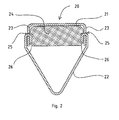
- FIG. 2 shows a mounting rail 20 according to the invention in cross section.
- the mounting rail 20 includes a U-shaped rail 21 and V-shaped armature 22. Over the entire length of the profile rail 21 shown here in section, a plurality of anchors 22 is provided.
- the mounting rail 20 may be three meters in length, for example, seven, eight or twenty anchors are distributed over the entire length of the rail 21.
- the arrangement of the anchor can be made at equal intervals.
- the distances can also be selected so that, for example, a rail with a length of three meters at a length of 1.5 meters is divisible.
- eight anchors may be distributed over a length of three meters such that the distance between the fourth and fifth anchors is less than the other distances, so that a division in the middle is possible, both sections four anchors in each case a suitable distance have the edge regions.
- the thickness of the rail can be selected depending on the intended applications. For example, the thickness of the profile rail can be 3 mm or 6 mm.
- the U-shaped profiled rail 21 comprises two lateral limbs 23, so that an interior space is bounded by the profiled rail 21.
- This interior is filled with a soft material 24, in particular with polystyrene.
- a styrofoam strand is preferably pre-cut with suitable dimensions and glued within the rail 21 with conventional Styoporklebern or comparable.
- the interior can be foamed, for example, with a plastic.
- a positive connection For connection or attachment of the armature 22 to the rail 21 a positive connection is provided.
- the open ends 26 of the armature 22 are bent twice for this purpose in the manner of a hook in the direction of the armature or in the direction of the opening of the U-shaped rail 21.
- the anchors 22 are fixedly and substantially permanently connected to the profiled rail 21, so that the fastening rail 20 is securely anchored when embedded in a concrete beam.
- the positive connection eliminates the need for conventional mounting railsberichtversch spaung the anchor with the rail.
- the fastening rail 20 realizes a hooking of the attachment end 26 of the armature 22 with the rail 21, wherein the bends are oriented in the opposite direction as the acting tensile force.
- To solve the inventive connection between the armature and rail therefore much higher forces would be required than is the case with the known mounting rail.
- a very stable connection between rail and armature is achieved with the mounting rail according to the invention, without a welding would be required.
- the armature 22 which is made for example of flat steel or round steel, initially bent in the region of the open ends 26 so that the ends are approximately at right angles to the inside, as in FIG. 3 is indicated by the dashed lines.
- the open ends 26 of the armature 22 are inserted into the openings 25 of the rail 21. Subsequently, the open ends 26 are bent once more in the direction of the armature, in particular by machine crimping, so that the armature 22 is fixedly connected to the rail 21.
- FIG. 4 an isometric view of the rail 21 is shown with an attached V-shaped anchor 22.
- the filling of the rail 21 with a soft material is not shown here for the sake of clarity.
- the fastening rail 20 according to the invention shown only as a section is continued in length, wherein a plurality of anchors 22 are arranged distributed over the entire length.
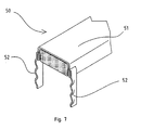
- FIG. 5 shows a further embodiment of the fastening rail 50 according to the invention.
- the armature 52 are designed in the form of band-shaped webs as a single anchor, which are arranged at opposite points on the longitudinal sides of the rail 51.
- the fastening anchors 52 are provided with a plurality of bulges 57, which further improve the anchoring and the maintenance of the mounting rail 50 in a concrete beam.
- openings 55 are provided on the side edges 53 of the rail, in each of which an open end 56 of the armature 52 are inserted.
- the open end 56 is first simply bent or pre-bent, here indicated by the dashed lines. This bend of the open end 56 is in the opening 55 of the rail introduced and then folded inside, so that the anchor 52 is connected in the manner of a hook with the rail 51.
- FIG. 7 shows an isometric view of the mounting rail 50.
- the mounting rail 50 is cut in the armature 52, wherein the individual anchors 52 are cut approximately along the center line.
- the rail 51 which is shown only in sections, continues in its length, with several anchors 52 are arranged at regular intervals.
- the anchor and the rail can be made either of stainless steel or steel, in particular of hot-dip galvanized steel.
- the advantage in the production of the fastening rail according to the invention is inter alia that the hot-dip galvanizing can be carried out before the assembly of the individual parts. In the known from the prior art mounting rails, this is not possible, since here the hot dip galvanizing can be made only after the welding of the anchor with the rail because the welding would damage a previously applied galvanizing.
Abstract
Description
Die vorliegende Erfindung betrifft eine Befestigungsschiene, die in Beton, insbesondere in einem Betonträger oder dergleichen einbettbar ist gemäß dem Oberbegriff des Anspruchs 1.The present invention relates to a fastening rail which can be embedded in concrete, in particular in a concrete beam or the like, according to the preamble of claim 1.
Zur Befestigung von Trapezblechen oder dergleichen auf Betonträgern oder anderen Gebäudeteilen sind Befestigungsschienen insbesondere aus Stahl bekannt, die in Betonteile eingebettet werden. Hierbei wird die Befestigungsschiene vorzugsweise bündig mit der Oberflächenkante des Betonteils in dieses einbetoniert. Die Befestigung von Trapezblechen oder dergleichen kann auf einfache Weise mittels selbstbohrender Schrauben oder Setzbolzen, die in das anzubringende Blech und in die Schiene eingedreht werden, vorgenommen werden. Aus baurechtlichen Gründen ist es vorgeschrieben, dass Trapezbleche auf Gebäudeteilen in Stahl und nicht in Beton verschraubt werden.For attachment of trapezoidal sheets or the like on concrete beams or other parts of buildings mounting rails are known in particular steel, which are embedded in concrete parts. Here, the mounting rail is preferably cast in flush with the surface edge of the concrete part in this. The attachment of trapezoidal sheets or the like can be done in a simple manner by means of self-drilling screws or setting bolts which are screwed into the sheet to be mounted and in the rail. For construction law reasons, it is mandatory that trapezoidal sheets are bolted to building parts in steel and not in concrete.
Das deutsche Gebrauchsmuster
Um die Herstellung von Befestigungsschienen herstellungstechnisch zu vereinfachen, schlägt die deutsche Patentschrift
Der Erfindung liegt die Aufgabe zugrunde, eine Befestigungsschiene bereitzustellen, die technisch einfach und mit wenig Aufwand herstellbar ist und dennoch allen Anforderungen an eine Befestigungsschiene im Hinblick auf Stabilität, Korrosionsbeständigkeit usw. genügt.The invention has for its object to provide a mounting rail, which is technically simple and can be produced with little effort and yet meets all requirements for a mounting rail in terms of stability, corrosion resistance, etc.
Diese Aufgabe wird durch eine Befestigungsschiene gelöst, wie es Gegenstand des Anspruchs 1 ist.This object is achieved by a mounting rail, as it is the subject of claim 1.
Die erfindungsgemäße Befestigungsschiene ist zur Einbettung in Beton, insbesondere in einen Betonträger oder dergleichen vorgesehen. Über die Befestigungsschiene in dem Betonträger können Trapezbleche oder andere Bauelemente auf einem Gebäudeteil befestigt werden, indem Schrauben oder Bolzen in die Befestigungsschiene eingedreht werden. Die Befestigungsschiene umfasst eine Profilschiene und eine Mehrzahl von an der Profilschiene angeordneten, in den Betonträger einzubettenden Ankern. Die Profilschiene weist zwei seitliche Schenkel auf, die einen Innenraum umgrenzen, der mit einem Weichstoffmaterial ausgefüllt ist. Die zwei seitlichen Schenkel der Profilschiene verlaufen vorzugsweise im Wesentlichen parallel, sodass die Profilschiene U-förmig ist. Hierbei ist die U-Form der Profilschiene nach unten, also in Richtung des Betons, offen. Der mit Weichstoffmaterial ausgefüllte Innenraum weist in das Innere des Betonträgers. Diese Schicht aus Weichstoffmaterial hält bei der Einbetonierung der Befestigungsschiene in einem Betonträger den Beton fern, sodass eine Schraube oder ein Bolzen, der zur Befestigung beispielsweise eines Trapezbleches in die Schiene eingedreht wird, nicht auf den Beton trifft. Die Anker dienen einer festen Verankerung der Befestigungsschiene im Betonträger. Dies ist erforderlich, da die Befestigungsschiene als Träger beispielsweise eines Trapezblechdaches einer erheblichen Belastung ausgesetzt ist. Die Anker sind formschlüssig mit der Profilschiene verbunden. Erfindungsgemäß ist hierbei vorgesehen, dass Umbiegungen der Anker an deren Befestigungsende in Öffnungen der seitlichen Schenkel der Profilschiene eingreifen. Die Öffnungen können beispielsweise als Längsschlitze ausgestaltet sein. Die Umbiegungen an den Befestigungsenden der Anker sind derart in Richtung des Ankers gebogen, dass ein etwa J-förmiger Haken gebildet wird, dessen kurzes Ende in Richtung der Öffnung der U-förmigen Profilschiene weist. Hierdurch wird eine sehr sichere und stabile Verbindung zwischen den Ankern und der Profilschiene erzielt, die auch erheblichen Zugbelastungen standhält, wie sie bei der Befestigung von Trapezblechen an in Betonträgern eingegossenen Befestigungsschienen durchaus auftreten können. Die formschlüssige sichere Verbindung zwischen den Ankern und der Profilschiene hat weiterhin den besonderen Vorteil, dass eine Verschweißung bei der Herstellung der Befestigungsschiene nicht erforderlich ist. Eine Verschweißung, wie sie aus dem Stand der Technik für derartige Befestigungsschienen bekannt ist, erfordert einen sehr hohen Aufwand bei der Herstellung der Befestigungsschiene und lässt sich nur schwer automatisieren. Der Formschluss gemäß der Erfindung zwischen den Ankern und der Profilschiene lässt sich hingegen mit wesentlich weniger Aufwand erreichen und ist insbesondere auch wesentlich besser einer Automatisierung zugänglich. Die Herstellung ist technisch wesentlich einfacher, sodass die erfindungsgemäßen Befestigungsschienen deutlich kostengünstiger hergestellt werden können. Auch im Vergleich mit der aus der Patentschrift bekannten
Bevorzugte Ausgestaltungen der erfindungsgemäßen Befestigungsschiene sind Gegenstand der abhängigen Ansprüche. So sind in einer besonders bevorzugten Ausführungsform der erfindungsgemäßen Befestigungsschiene die Anker bügelförmig, wobei die offenen Enden bzw. die Befestigungsenden der bügelförmigen Anker die Umbiegungen ausbilden, die zum Eingriff in die Öffnungen der Profilschiene vorgesehen sind. Hierbei sind die beiden Enden eines bügelförmigen Ankers an sich gegenüberliegenden Punkten der seitlichen Schenkel der Befestigungsschiene angeordnet. Vorzugsweise ist der bügelförmige Anker im Wesentlichen V-förmig. In anderen Ausführungsformen kann der bügelförmige Anker beispielsweise auch U-förmig oder rechteckförmig sein. Er kann beispielsweise aus einem Flachstahl hergestellt sein. Der Ankerbügel kann gleichfalls mit Vorteil aus gebogenem Rundstahl gefertigt sein. Die Öffnungen in den seitlichen Schenkeln der Profilschienen sind vorzugsweise an die Form des Ankers, beispielsweise an die Abmessungen des Flachstahls oder an den Durchmesser des gebogenen Rundstahls angepasst. So sind bei der Verwendung von Flachstahl für den Anker vorzugsweise schlitzförmige Öffnungen und bei der Verwendung von gebogenem Rundstahl für den Anker entsprechende kreisförmige Öffnungen vorgesehen.Preferred embodiments of the fastening rail according to the invention are the subject of the dependent claims. Thus, in a particularly preferred embodiment of the mounting rail according to the invention, the armature bow-shaped, wherein the open ends and the attachment ends of the bow-shaped armature form the bends, which are provided for engagement in the openings of the rail. Here are the two ends a bow-shaped armature arranged at opposite points of the lateral legs of the mounting rail. Preferably, the bow-shaped armature is substantially V-shaped. In other embodiments, the bow-shaped armature may for example also be U-shaped or rectangular. It can for example be made of a flat steel. The anchor bracket can also be made with advantage of curved round steel. The openings in the lateral limbs of the profile rails are preferably adapted to the shape of the armature, for example to the dimensions of the flat steel or to the diameter of the bent round steel. Thus, in the use of flat steel for the anchor preferably slot-shaped openings and in the use of curved round steel for the anchor corresponding circular openings are provided.
In einer anderen Ausführungsform der erfindungsgemäßen Befestigungsschiene sind die Anker bandförmige Stege, wobei ein offenes Ende der bandförmigen Stege die Umbiegung ausbildet, die zum Eingriff in die Profilschiene vorgesehen ist. Das andere Ende des bandförmigen Steges ragt nach der Einbettung der Befestigungsschiene frei in den Beton hinein. Vorzugsweise sind zwei der bandförmigen Stege einander gegenüberliegend an den Längsseiten der Profilschienen angeordnet.In another embodiment of the fastening rail according to the invention, the armature band-shaped webs, wherein an open end of the band-shaped webs forms the bend, which is provided for engagement in the rail. The other end of the band-shaped ridge protrudes freely into the concrete after the embedding of the fastening rail. Preferably, two of the band-shaped webs are arranged opposite one another on the longitudinal sides of the profile rails.
Gemäß einer bevorzugten Ausführungsform der erfindungsgemäßen Befestigungsschiene sind die Anker und insbesondere die bandförmigen Stege als Anker mit Mitteln zur Verbesserung des Halts innerhalb des Betonträgers ausgestattet. Beispielsweise weisen die bandförmigen Stege Ausbuchtungen, Einbuchtungen oder Aussparungen auf, die beim Einbetonieren der erfindungsgemäßen Befestigungsschiene in einem Betonträger in dem Beton eingeschlossen werden bzw. in die der Beton eindringt, sodass der Halt der Anker im Beton und damit die Stabilität der erfindungsgemäßen Befestigungsschiene weiter verbessert wird.According to a preferred embodiment of the fastening rail according to the invention, the anchors and in particular the band-shaped webs are equipped as anchors with means for improving the support within the concrete support. For example, the band-shaped webs on recesses, indentations or recesses, which are included in the concrete in the concrete when concrete railing of the invention in a concrete beam or in the concrete penetrates, so that the support of the anchor in the concrete and thus the stability of the mounting rail according to the invention further improved becomes.
Die Umbiegungen der Anker können entweder von außen nach innen oder von innen nach außen in die seitlichen Schenkel der Profilschiene eingreifen, wobei das Eingreifen von außen nach innen gegebenenfalls herstellungstechnisch einfacher zu realisieren ist und damit besonders bevorzugt ist.The bends of the armature can engage either from outside to inside or from the inside to the outside in the side legs of the rail, the intervention from the outside to the inside, where appropriate, manufacturing technology easier to implement and is therefore particularly preferred.
Das Weichstoffmaterial kann beispielsweise in den Innenraum der Profilschiene eingeschäumt sein, beispielsweise als Schaumstoff. Besonders bevorzugt ist eine Styroporfüllung des Innenraums, wobei ein entsprechend vorgeschnittener Styroporstrang in den Innenraum eingeklebt sein kann.The soft material may, for example, be foamed into the interior of the profile rail, for example as a foam. Particularly preferred is a styrofoam filling the interior, wherein a corresponding pre-cut Styrofoam strand can be glued into the interior.
Vorzugsweise bestehen die Befestigungsschiene bzw. die Profilschiene und die Anker aus Stahl, insbesondere aus verzinktem, vorzugsweise feuerverzinktem Stahl. Die Feuerverzinkung des Stahls gewährleistet eine ausreichende Korrosionsbeständigkeit der erfindungsgemäßen Befestigungsschiene. In einer anderen sehr hochwertigen Ausführungsform sind die Befestigungsschiene bzw. die Profilschiene und die Anker aus Edelstahl gefertigt. In anderen Ausführungsformen können auch feuerverzinkter Stahl und Edelstahl miteinander kombiniert sein, indem beispielsweise die Profilschiene aus Edelstahl und die Anker aus feuerverzinktem Stahl bestehen.Preferably, the mounting rail or the rail and the anchor made of steel, in particular of galvanized, preferably hot-dip galvanized steel. The hot-dip galvanizing of the steel ensures sufficient corrosion resistance of the fastening rail according to the invention. In another very high-quality embodiment, the mounting rail or the rail and the anchor are made of stainless steel. In other embodiments, hot dip galvanized steel and stainless steel can be combined with each other, for example, by the profile rail made of stainless steel and the anchor made of hot-dip galvanized steel.
Zur Herstellung der erfindungsgemäßen Befestigungsschiene wird zunächst eine Profilschiene mit zwei seitlichen Schenkeln, insbesondere eine U-förmige Profilschiene, bereitgestellt. Die seitlichen Schenkel der Profilschiene werden mit Öffnungen versehen, die zur formschlüssigen Befestigung der Anker vorgesehen sind. Vorzugsweise werden die Öffnungen in regelmäßigen Abständen angebracht. Hierbei können je nach Anwendungsfall die Anzahl der erforderlichen Anker pro Schiene und abhängig davon unterschiedliche Abstände gewählt werden. Die offenen Enden der Anker werden umgebogen bzw. vorgebogen und in die Öffnungen eingeführt. Die offenen Enden der Anker werden nach der Einführung in die Öffnungen auf der anderen Seite nochmals in Richtung des Ankers in hakenartiger Weise umgebogen, beispielsweise umgefalzt. Ein von den seitlichen Schenkeln der Profilschiene umgrenzter Innenraum wird mit einem Weichstoffmaterial ausgefüllt. Dieses Herstellungsverfahren ist technisch einfach ausführbar und kann mit besonderem Vorteil automatisiert werden, sodass die erfindungsgemäße Befestigungsschiene sehr kostengünstig herstellbar ist.To produce the fastening rail according to the invention, first of all a profiled rail with two lateral limbs, in particular a U-shaped profiled rail, is provided. The lateral legs of the rail are provided with openings which are provided for the positive fastening of the anchor. Preferably, the openings are attached at regular intervals. Here, depending on the application, the number of required anchors per rail and depending on different distances can be selected. The open ends of the anchors are bent or pre-bent and inserted into the openings. The open ends of the anchors become after the introduction into the Receptacles on the other side again bent in the direction of the anchor in a hook-like manner, for example folded over. An enclosed by the lateral limbs of the rail interior is filled with a soft material. This manufacturing method is technically easy to perform and can be automated with particular advantage, so that the mounting rail according to the invention is very inexpensive to produce.
Herstellungstechnisch besonders vorteilhaft ist die Einfügung der Umbiegungen der Anker von außen nach innen in die Öffnungen der seitlichen Schenkel der Profilschiene. Die seitlichen Schenkel eines V-förmig oder U-förmig vorgebogenen Ankers können beispielsweise leicht etwas auseinandergezogen werden und dann in die Öffnungen jeweils von außen eingefügt werden. Bei dem Vorbiegen der beispielsweise V-förmigen oder U-förmigen Anker werden die offenen Enden nach innen umgebogen. In einer anderen Ausführungsform können die Umbiegungen eines V-förmigen oder U-förmigen Ankers jeweils nach außen vorgenommen werden, sodass die seitlichen Schenkel der Anker etwas zusammengebogen und in das Innere der Profilschiene eingeführt werden, sodass die Umbiegungen von innen nach außen in die Öffnungen der seitlichen Schenkel der Profilschiene eingefügt werden. Auch diese Ausführungsform kann bevorzugt sein, da die Angriffspunkte für das weitere Umfalzen der Umbiegungen hierbei sehr gut zugänglich sind.Manufacturing technology particularly advantageous is the insertion of the bends of the anchor from outside to inside in the openings of the side legs of the rail. For example, the lateral legs of a V-shaped or U-shaped pre-bent anchor can be slightly pulled apart and then inserted into the openings from the outside, respectively. In the pre-bending of the example V-shaped or U-shaped anchors, the open ends are bent inwards. In another embodiment, the bends of a V-shaped or U-shaped anchor can be made outwardly, respectively, so that the lateral legs of the anchors are slightly bent together and inserted into the interior of the rail, so that the bends from the inside to the outside in the openings lateral legs of the rail to be inserted. This embodiment may also be preferred, since the points of attack for the further folding of the bends are very easily accessible in this case.
Zur Einbringung des Weichstoffmaterials in das Innere der Profilschiene wird mit besonderem Vorteil ein Styroporstrang vorgeschnitten und in den Innenraum der Profilschiene mit üblichen Styroporklebern eingeklebt. In anderen Ausführungsformen kann der Innenraum mit Schaumstoffen oder Vergleichbarem ausgeschäumt werden.For introducing the soft material into the interior of the rail, a styrofoam strand is pre-cut with particular advantage and glued into the interior of the rail with conventional Styoporklebern. In other embodiments, the interior can be foamed with foams or similar.
Gegenüber herkömmlichen Herstellungsverfahren für Befestigungsschienen erlaubt die Herstellung der erfindungsgemäßen Befestigungsschiene eine Feuerverzinkung der Einzelteile vor deren Montage. Dies ist herstellungstechnisch besonders vorteilhaft, da die Feuerverzinkung der Einzelteile mit weniger Aufwand durchführbar ist als die Feuerverzinkung der komplexen Befestigungsschiene. Bei aus dem Stand der Technik bekannten geschweißten Befestigungsschienen ist es erforderlich, die komplette Befestigungsschiene zu verzinken, da durch das Anschweißen der Anker an die Befestigungsschiene eine zuvor durchgeführte Verzinkung beschädigt werden würde.Compared to conventional manufacturing methods for mounting rails allows the production of the mounting rail according to the invention a Hot dip galvanizing of the items before assembly. This is manufacturing technology particularly advantageous because the hot dip galvanizing of the items with less effort is feasible than the hot dip galvanizing the complex mounting rail. In known from the prior art welded mounting rails, it is necessary to galvanize the entire mounting rail, as by welding the anchor to the mounting rail a previously performed galvanizing would be damaged.
Weitere Merkmale und Vorteile der Erfindung ergeben sich aus der nachfolgenden Beschreibung von Ausführungsbeispielen im Zusammenhang mit den Zeichnungen. Hierbei können die einzelnen Merkmale jeweils für sich oder in Kombination miteinander verwirklicht sein.Further features and advantages of the invention will become apparent from the following description of embodiments in conjunction with the drawings. In this case, the individual features can be implemented individually or in combination with each other.
In den Zeichnungen zeigen:
- Figur 1
- eine isometrische Darstellung einer Befestigungsschiene aus dem Stand der Technik, die in einem Betonträger eingebettet ist, mit einem an der Befestigungsschiene befestigten Trapezblech;
Figur 2- eine Schnittdarstellung einer ersten Ausführungsform der erfindungsgemäßen Befestigungsschiene;
Figur 3- eine Schnittdarstellung eines Befestigungsankers der Befestigungsschiene aus
Figur 2 ; - Figur 4
- eine isometrische Darstellung der Profilschiene und eines Befestigungsankers der ersten Ausführungsform der erfindungsgemäßen Befestigungsschiene;
Figur 5- eine Schnittdarstellung einer zweiten Ausführungsform der erfindungsgemäßen Befestigungsschiene;
Figur 6- eine Schnittdarstellung eines Ankers der erfindungsgemäßen Befestigungsschiene aus
Figur 5 und Figur 7- eine isometrische Darstellung der erfindungsgemäßen Befestigungsschiene aus
Figur 5 .
- FIG. 1
- an isometric view of a mounting rail of the prior art, which is embedded in a concrete beam, with a fixed to the mounting rail trapezoidal sheet metal;
- FIG. 2
- a sectional view of a first embodiment of the fastening rail according to the invention;
- FIG. 3
- a sectional view of a mounting anchor of the mounting rail
FIG. 2 ; - FIG. 4
- an isometric view of the rail and a mounting anchor of the first embodiment of the mounting rail according to the invention;
- FIG. 5
- a sectional view of a second embodiment of the fastening rail according to the invention;
- FIG. 6
- a sectional view of an anchor of the mounting rail according to the invention
FIG. 5 and - FIG. 7
- an isometric view of the mounting rail according to the invention
FIG. 5 ,
Die U-förmige Profilschiene 21 umfasst zwei seitliche Schenkel 23, sodass von der Profilschiene 21 ein Innenraum umgrenzt wird. Dieser Innenraum ist mit einem weichen Material 24, insbesondere mit Styropor ausgefüllt. Zur Einbringung des Styropors 24 in den Innenraum der Profilschiene 21 wird vorzugsweise ein Styroporstrang mit geeigneten Abmessungen vorgeschnitten und innerhalb der Profilschiene 21 mit üblichen Styroporklebern oder Vergleichbarem eingeklebt. In anderen Ausführungsformen kann der Innenraum beispielsweise mit einem Kunststoff ausgeschäumt werden.The U-shaped profiled
Zur Verbindung bzw. zur Befestigung des Ankers 22 an der Profilschiene 21 ist ein Formschluss vorgesehen. Hierfür weisen die seitlichen Schenkel 23 der Profilschiene 21 Öffnungen 25 auf, in die die offenen Enden 26 des Ankers eingreifen. Die offenen Enden 26 des Ankers 22 sind hierfür nach Art eines Hakens zweifach in Richtung des Ankers bzw. in Richtung der Öffnung der U-förmigen Profilschiene 21 umgebogen. Durch diesen Formschluss sind die Anker 22 fest und im Wesentlichen unlösbar mit der Profilschiene 21 verbunden, sodass die Befestigungsschiene 20 bei einer Einbettung in einem Betonträger sicher verankert ist. Durch den Formschluss entfällt die bei herkömmlichen Befestigungsschienen erforderliche Punktverschweißung der Anker mit der Profilschiene. Der Formschluss ist fertigungstechnisch wesentlich einfacher und kostengünstiger zu bewerkstelligen und erzielt im Ergebnis im Wesentlichen die gleiche Stabilität wie eine Punktverschweißung der Anker. Im Vergleich mit der aus der
Die erfindungsgemäße Befestigungsschiene 20 hingegen realisiert eine Verhakung des Befestigungsendes 26 des Ankers 22 mit der Profilschiene 21, wobei die Umbiegungen in entgegengesetzter Richtung wie die wirkende Zugkraft orientiert sind. Zur Lösung der erfindungsgemäßen Verbindung zwischen Anker und Profilschiene wären daher wesentlich höhere Kräfte erforderlich, als es bei der bekannten Befestigungsschiene der Fall ist. Insgesamt wird mit der erfindungsgemäßen Befestigungsschiene also eine sehr stabile Verbindung zwischen Profilschiene und Anker erreicht, ohne dass eine Verschweißung erforderlich wäre.The
Für die Montage der erfindungsgemäßen Befestigungsschiene 20 wird der Anker 22, der beispielsweise aus Flachstahl oder Rundstahl hergestellt ist, im Bereich der offenen Enden 26 zunächst so vorgebogen, dass die Enden etwa im rechten Winkel nach innen stehen, wie es in
In
Die Anker und die Profilschiene können entweder aus Edelstahl oder aus Stahl, insbesondere aus feuerverzinktem Stahl gefertigt sein. Der Vorteil bei der Herstellung der erfindungsgemäßen Befestigungsschiene ist unter anderem, dass die Feuerverzinkung vor der Montage der einzelnen Teile durchgeführt werden kann. Bei den aus dem Stand der Technik bekannten Befestigungsschienen ist dies nicht möglich, da hier die Feuerverzinkung erst nach der Verschweißung der Anker mit der Profilschiene vorgenommen werden kann, da die Verschweißung eine vorher aufgebrachte Verzinkung beschädigen würde.The anchor and the rail can be made either of stainless steel or steel, in particular of hot-dip galvanized steel. The advantage in the production of the fastening rail according to the invention is inter alia that the hot-dip galvanizing can be carried out before the assembly of the individual parts. In the known from the prior art mounting rails, this is not possible, since here the hot dip galvanizing can be made only after the welding of the anchor with the rail because the welding would damage a previously applied galvanizing.
Claims (9)
Applications Claiming Priority (1)
| Application Number | Priority Date | Filing Date | Title |
|---|---|---|---|
| DE200920015920 DE202009015920U1 (en) | 2009-11-23 | 2009-11-23 | mounting rail |
Publications (2)
| Publication Number | Publication Date |
|---|---|
| EP2333176A1 true EP2333176A1 (en) | 2011-06-15 |
| EP2333176B1 EP2333176B1 (en) | 2013-10-30 |
Family
ID=41821748
Family Applications (1)
| Application Number | Title | Priority Date | Filing Date |
|---|---|---|---|
| EP20100014792 Not-in-force EP2333176B1 (en) | 2009-11-23 | 2010-11-19 | Attachment rail |
Country Status (2)
| Country | Link |
|---|---|
| EP (1) | EP2333176B1 (en) |
| DE (1) | DE202009015920U1 (en) |
Families Citing this family (1)
| Publication number | Priority date | Publication date | Assignee | Title |
|---|---|---|---|---|
| EP3710644A1 (en) * | 2017-11-16 | 2020-09-23 | Chryso Italia S.R.L. | Anchoring device for structural profiles |
Citations (9)
| Publication number | Priority date | Publication date | Assignee | Title |
|---|---|---|---|---|
| DE455572C (en) * | 1928-02-01 | Hugo Bodemann | U-shaped anchor rail to be embedded in the concrete body | |
| US1768246A (en) * | 1928-01-23 | 1930-06-24 | Globe Machine & Stamping Co | Insert for concrete |
| DE7524212U (en) | 1975-12-04 | Halfeneisen Gmbh & Co Kg | Mounting rail for attaching trapezoidal sheets | |
| EP0340927A1 (en) * | 1988-04-14 | 1989-11-08 | Vantrunk Engineering Limited | Insert for a channel section member |
| DE3912169C1 (en) | 1989-04-13 | 1990-12-13 | Deutsche Kahneisen Gesellschaft West Mbh, 1000 Berlin, De | |
| DE3926416A1 (en) | 1989-08-10 | 1991-02-21 | Halfeneisen Gmbh & Co Kg | MOUNTING RAIL IN CONCRETE CARRIERS OR THE LIKE EMBEDDED |
| EP0436165A2 (en) * | 1990-01-05 | 1991-07-10 | Sergio Zambelli | Profiled anchor element structure for prefabricated concrete componets |
| WO1997022764A1 (en) * | 1995-12-19 | 1997-06-26 | Ancon Clark Limited | Channel |
| DE19725882A1 (en) * | 1997-06-18 | 1998-12-24 | Modersohn Gmbh & Co Kg Wilh | Anchor rail for hammer head screws, brick connection anchors or similar to concrete structural bodies |
-
2009
- 2009-11-23 DE DE200920015920 patent/DE202009015920U1/en not_active Expired - Lifetime
-
2010
- 2010-11-19 EP EP20100014792 patent/EP2333176B1/en not_active Not-in-force
Patent Citations (9)
| Publication number | Priority date | Publication date | Assignee | Title |
|---|---|---|---|---|
| DE455572C (en) * | 1928-02-01 | Hugo Bodemann | U-shaped anchor rail to be embedded in the concrete body | |
| DE7524212U (en) | 1975-12-04 | Halfeneisen Gmbh & Co Kg | Mounting rail for attaching trapezoidal sheets | |
| US1768246A (en) * | 1928-01-23 | 1930-06-24 | Globe Machine & Stamping Co | Insert for concrete |
| EP0340927A1 (en) * | 1988-04-14 | 1989-11-08 | Vantrunk Engineering Limited | Insert for a channel section member |
| DE3912169C1 (en) | 1989-04-13 | 1990-12-13 | Deutsche Kahneisen Gesellschaft West Mbh, 1000 Berlin, De | |
| DE3926416A1 (en) | 1989-08-10 | 1991-02-21 | Halfeneisen Gmbh & Co Kg | MOUNTING RAIL IN CONCRETE CARRIERS OR THE LIKE EMBEDDED |
| EP0436165A2 (en) * | 1990-01-05 | 1991-07-10 | Sergio Zambelli | Profiled anchor element structure for prefabricated concrete componets |
| WO1997022764A1 (en) * | 1995-12-19 | 1997-06-26 | Ancon Clark Limited | Channel |
| DE19725882A1 (en) * | 1997-06-18 | 1998-12-24 | Modersohn Gmbh & Co Kg Wilh | Anchor rail for hammer head screws, brick connection anchors or similar to concrete structural bodies |
Also Published As
| Publication number | Publication date |
|---|---|
| EP2333176B1 (en) | 2013-10-30 |
| DE202009015920U1 (en) | 2010-03-11 |
Similar Documents
| Publication | Publication Date | Title |
|---|---|---|
| DE3736553A1 (en) | WALL CONNECTOR | |
| EP3081708B1 (en) | Anchor rail for anchoring in concrete | |
| EP2163699B1 (en) | Connection profile | |
| EP2963205B1 (en) | Device for formwork | |
| EP2388382A2 (en) | Mounting rail | |
| EP1601842B1 (en) | Reinforcing elements and reinforced concrete or prestressed concrete parts produced by means of the same | |
| DE102006052648B4 (en) | Support anchor for fastening facade elements to a building wall, building wall construction and use of a support anchor | |
| DE102007005351A1 (en) | module | |
| EP2333176B1 (en) | Attachment rail | |
| DE102005005745C5 (en) | Profile plate for covering a building roof and building roof | |
| DE102010012537A1 (en) | Reinforcing bar for connecting two wall shells of prefabricated wall in building, has tooth-shaped notches arranged at end region and evenly arranged in longitudinal direction, and elongated body tapered at end region | |
| DE102016118491A1 (en) | Method for mounting insulation panels on a building wall and set of elements for mounting insulation panels on a building wall | |
| EP0692585B1 (en) | Form-element | |
| EP1703036B1 (en) | Construction element for shear and punching reinforcement | |
| EP0412445A2 (en) | Rail to be embedded in concrete girders or same | |
| EP1972734A1 (en) | Retaining body for an insulating board | |
| DE102017101509A1 (en) | Console for fixing facade elements | |
| DE202020100059U1 (en) | Formwork element | |
| EP0162063B1 (en) | Securing device | |
| EP3892789A1 (en) | Cladding system | |
| EP3091167A1 (en) | Fastening element for attaching a window frame to a ceiling of a structure, associated structure and method for fixing a frame of a window to a ceiling | |
| DE102011056105B4 (en) | Mounting accessory for mounting components, e.g. Basement light shafts on building walls | |
| DE4002001A1 (en) | Anchoring equipment for protruding portion of building - comprises latticework girder forming reinforcement | |
| EP2019173B1 (en) | Formwork element for lost formwork concrete construction and formwork made of such formwork elements | |
| EP0495186B1 (en) | Welded supporting anchor for anchoring façade-covering plates |
Legal Events
| Date | Code | Title | Description |
|---|---|---|---|
| PUAI | Public reference made under article 153(3) epc to a published international application that has entered the european phase |
Free format text: ORIGINAL CODE: 0009012 |
|
| AK | Designated contracting states |
Kind code of ref document: A1 Designated state(s): AL AT BE BG CH CY CZ DE DK EE ES FI FR GB GR HR HU IE IS IT LI LT LU LV MC MK MT NL NO PL PT RO RS SE SI SK SM TR |
|
| AX | Request for extension of the european patent |
Extension state: BA ME |
|
| 17P | Request for examination filed |
Effective date: 20110804 |
|
| RAP1 | Party data changed (applicant data changed or rights of an application transferred) |
Owner name: PROFILANKER GMBH |
|
| GRAP | Despatch of communication of intention to grant a patent |
Free format text: ORIGINAL CODE: EPIDOSNIGR1 |
|
| RIC1 | Information provided on ipc code assigned before grant |
Ipc: E04B 1/41 20060101AFI20130417BHEP |
|
| INTG | Intention to grant announced |
Effective date: 20130523 |
|
| GRAS | Grant fee paid |
Free format text: ORIGINAL CODE: EPIDOSNIGR3 |
|
| GRAA | (expected) grant |
Free format text: ORIGINAL CODE: 0009210 |
|
| AK | Designated contracting states |
Kind code of ref document: B1 Designated state(s): AL AT BE BG CH CY CZ DE DK EE ES FI FR GB GR HR HU IE IS IT LI LT LU LV MC MK MT NL NO PL PT RO RS SE SI SK SM TR |
|
| REG | Reference to a national code |
Ref country code: GB Ref legal event code: FG4D Free format text: NOT ENGLISH |
|
| REG | Reference to a national code |
Ref country code: CH Ref legal event code: EP |
|
| REG | Reference to a national code |
Ref country code: AT Ref legal event code: REF Ref document number: 638534 Country of ref document: AT Kind code of ref document: T Effective date: 20131115 |
|
| REG | Reference to a national code |
Ref country code: IE Ref legal event code: FG4D Free format text: LANGUAGE OF EP DOCUMENT: GERMAN |
|
| REG | Reference to a national code |
Ref country code: DE Ref legal event code: R096 Ref document number: 502010005205 Country of ref document: DE Effective date: 20131224 |
|
| REG | Reference to a national code |
Ref country code: NL Ref legal event code: VDEP Effective date: 20131030 |
|
| REG | Reference to a national code |
Ref country code: LT Ref legal event code: MG4D |
|
| PG25 | Lapsed in a contracting state [announced via postgrant information from national office to epo] |
Ref country code: NO Free format text: LAPSE BECAUSE OF FAILURE TO SUBMIT A TRANSLATION OF THE DESCRIPTION OR TO PAY THE FEE WITHIN THE PRESCRIBED TIME-LIMIT Effective date: 20140130 Ref country code: FI Free format text: LAPSE BECAUSE OF FAILURE TO SUBMIT A TRANSLATION OF THE DESCRIPTION OR TO PAY THE FEE WITHIN THE PRESCRIBED TIME-LIMIT Effective date: 20131030 Ref country code: LT Free format text: LAPSE BECAUSE OF FAILURE TO SUBMIT A TRANSLATION OF THE DESCRIPTION OR TO PAY THE FEE WITHIN THE PRESCRIBED TIME-LIMIT Effective date: 20131030 Ref country code: HR Free format text: LAPSE BECAUSE OF FAILURE TO SUBMIT A TRANSLATION OF THE DESCRIPTION OR TO PAY THE FEE WITHIN THE PRESCRIBED TIME-LIMIT Effective date: 20131030 Ref country code: SE Free format text: LAPSE BECAUSE OF FAILURE TO SUBMIT A TRANSLATION OF THE DESCRIPTION OR TO PAY THE FEE WITHIN THE PRESCRIBED TIME-LIMIT Effective date: 20131030 Ref country code: IS Free format text: LAPSE BECAUSE OF FAILURE TO SUBMIT A TRANSLATION OF THE DESCRIPTION OR TO PAY THE FEE WITHIN THE PRESCRIBED TIME-LIMIT Effective date: 20140228 Ref country code: NL Free format text: LAPSE BECAUSE OF FAILURE TO SUBMIT A TRANSLATION OF THE DESCRIPTION OR TO PAY THE FEE WITHIN THE PRESCRIBED TIME-LIMIT Effective date: 20131030 |
|
| PG25 | Lapsed in a contracting state [announced via postgrant information from national office to epo] |
Ref country code: RS Free format text: LAPSE BECAUSE OF FAILURE TO SUBMIT A TRANSLATION OF THE DESCRIPTION OR TO PAY THE FEE WITHIN THE PRESCRIBED TIME-LIMIT Effective date: 20131030 Ref country code: LV Free format text: LAPSE BECAUSE OF FAILURE TO SUBMIT A TRANSLATION OF THE DESCRIPTION OR TO PAY THE FEE WITHIN THE PRESCRIBED TIME-LIMIT Effective date: 20131030 Ref country code: ES Free format text: LAPSE BECAUSE OF FAILURE TO SUBMIT A TRANSLATION OF THE DESCRIPTION OR TO PAY THE FEE WITHIN THE PRESCRIBED TIME-LIMIT Effective date: 20131030 Ref country code: CY Free format text: LAPSE BECAUSE OF FAILURE TO SUBMIT A TRANSLATION OF THE DESCRIPTION OR TO PAY THE FEE WITHIN THE PRESCRIBED TIME-LIMIT Effective date: 20131030 |
|
| BERE | Be: lapsed |
Owner name: PROFILANKER G.M.B.H. Effective date: 20131130 |
|
| PG25 | Lapsed in a contracting state [announced via postgrant information from national office to epo] |
Ref country code: PT Free format text: LAPSE BECAUSE OF FAILURE TO SUBMIT A TRANSLATION OF THE DESCRIPTION OR TO PAY THE FEE WITHIN THE PRESCRIBED TIME-LIMIT Effective date: 20140228 |
|
| PG25 | Lapsed in a contracting state [announced via postgrant information from national office to epo] |
Ref country code: MC Free format text: LAPSE BECAUSE OF FAILURE TO SUBMIT A TRANSLATION OF THE DESCRIPTION OR TO PAY THE FEE WITHIN THE PRESCRIBED TIME-LIMIT Effective date: 20131030 Ref country code: EE Free format text: LAPSE BECAUSE OF FAILURE TO SUBMIT A TRANSLATION OF THE DESCRIPTION OR TO PAY THE FEE WITHIN THE PRESCRIBED TIME-LIMIT Effective date: 20131030 |
|
| REG | Reference to a national code |
Ref country code: DE Ref legal event code: R097 Ref document number: 502010005205 Country of ref document: DE |
|
| REG | Reference to a national code |
Ref country code: IE Ref legal event code: MM4A |
|
| PG25 | Lapsed in a contracting state [announced via postgrant information from national office to epo] |
Ref country code: IT Free format text: LAPSE BECAUSE OF FAILURE TO SUBMIT A TRANSLATION OF THE DESCRIPTION OR TO PAY THE FEE WITHIN THE PRESCRIBED TIME-LIMIT Effective date: 20131030 Ref country code: SK Free format text: LAPSE BECAUSE OF FAILURE TO SUBMIT A TRANSLATION OF THE DESCRIPTION OR TO PAY THE FEE WITHIN THE PRESCRIBED TIME-LIMIT Effective date: 20131030 Ref country code: RO Free format text: LAPSE BECAUSE OF FAILURE TO SUBMIT A TRANSLATION OF THE DESCRIPTION OR TO PAY THE FEE WITHIN THE PRESCRIBED TIME-LIMIT Effective date: 20131030 Ref country code: PL Free format text: LAPSE BECAUSE OF FAILURE TO SUBMIT A TRANSLATION OF THE DESCRIPTION OR TO PAY THE FEE WITHIN THE PRESCRIBED TIME-LIMIT Effective date: 20131030 Ref country code: CZ Free format text: LAPSE BECAUSE OF FAILURE TO SUBMIT A TRANSLATION OF THE DESCRIPTION OR TO PAY THE FEE WITHIN THE PRESCRIBED TIME-LIMIT Effective date: 20131030 |
|
| PLBE | No opposition filed within time limit |
Free format text: ORIGINAL CODE: 0009261 |
|
| STAA | Information on the status of an ep patent application or granted ep patent |
Free format text: STATUS: NO OPPOSITION FILED WITHIN TIME LIMIT |
|
| PG25 | Lapsed in a contracting state [announced via postgrant information from national office to epo] |
Ref country code: DK Free format text: LAPSE BECAUSE OF FAILURE TO SUBMIT A TRANSLATION OF THE DESCRIPTION OR TO PAY THE FEE WITHIN THE PRESCRIBED TIME-LIMIT Effective date: 20131030 Ref country code: BE Free format text: LAPSE BECAUSE OF NON-PAYMENT OF DUE FEES Effective date: 20131130 |
|
| 26N | No opposition filed |
Effective date: 20140731 |
|
| REG | Reference to a national code |
Ref country code: FR Ref legal event code: ST Effective date: 20140922 |
|
| PG25 | Lapsed in a contracting state [announced via postgrant information from national office to epo] |
Ref country code: IE Free format text: LAPSE BECAUSE OF NON-PAYMENT OF DUE FEES Effective date: 20131119 |
|
| REG | Reference to a national code |
Ref country code: DE Ref legal event code: R097 Ref document number: 502010005205 Country of ref document: DE Effective date: 20140731 |
|
| PG25 | Lapsed in a contracting state [announced via postgrant information from national office to epo] |
Ref country code: FR Free format text: LAPSE BECAUSE OF NON-PAYMENT OF DUE FEES Effective date: 20131230 |
|
| PG25 | Lapsed in a contracting state [announced via postgrant information from national office to epo] |
Ref country code: SI Free format text: LAPSE BECAUSE OF FAILURE TO SUBMIT A TRANSLATION OF THE DESCRIPTION OR TO PAY THE FEE WITHIN THE PRESCRIBED TIME-LIMIT Effective date: 20131030 |
|
| PG25 | Lapsed in a contracting state [announced via postgrant information from national office to epo] |
Ref country code: SM Free format text: LAPSE BECAUSE OF FAILURE TO SUBMIT A TRANSLATION OF THE DESCRIPTION OR TO PAY THE FEE WITHIN THE PRESCRIBED TIME-LIMIT Effective date: 20131030 |
|
| PG25 | Lapsed in a contracting state [announced via postgrant information from national office to epo] |
Ref country code: TR Free format text: LAPSE BECAUSE OF FAILURE TO SUBMIT A TRANSLATION OF THE DESCRIPTION OR TO PAY THE FEE WITHIN THE PRESCRIBED TIME-LIMIT Effective date: 20131030 |
|
| REG | Reference to a national code |
Ref country code: CH Ref legal event code: PL |
|
| GBPC | Gb: european patent ceased through non-payment of renewal fee |
Effective date: 20141119 |
|
| PG25 | Lapsed in a contracting state [announced via postgrant information from national office to epo] |
Ref country code: LU Free format text: LAPSE BECAUSE OF NON-PAYMENT OF DUE FEES Effective date: 20131119 Ref country code: MK Free format text: LAPSE BECAUSE OF FAILURE TO SUBMIT A TRANSLATION OF THE DESCRIPTION OR TO PAY THE FEE WITHIN THE PRESCRIBED TIME-LIMIT Effective date: 20131030 Ref country code: CH Free format text: LAPSE BECAUSE OF NON-PAYMENT OF DUE FEES Effective date: 20141130 Ref country code: LI Free format text: LAPSE BECAUSE OF NON-PAYMENT OF DUE FEES Effective date: 20141130 Ref country code: BG Free format text: LAPSE BECAUSE OF FAILURE TO SUBMIT A TRANSLATION OF THE DESCRIPTION OR TO PAY THE FEE WITHIN THE PRESCRIBED TIME-LIMIT Effective date: 20131030 Ref country code: HU Free format text: LAPSE BECAUSE OF FAILURE TO SUBMIT A TRANSLATION OF THE DESCRIPTION OR TO PAY THE FEE WITHIN THE PRESCRIBED TIME-LIMIT; INVALID AB INITIO Effective date: 20101119 |
|
| PG25 | Lapsed in a contracting state [announced via postgrant information from national office to epo] |
Ref country code: MT Free format text: LAPSE BECAUSE OF FAILURE TO SUBMIT A TRANSLATION OF THE DESCRIPTION OR TO PAY THE FEE WITHIN THE PRESCRIBED TIME-LIMIT Effective date: 20131030 Ref country code: GR Free format text: LAPSE BECAUSE OF NON-PAYMENT OF DUE FEES Effective date: 20131030 |
|
| PG25 | Lapsed in a contracting state [announced via postgrant information from national office to epo] |
Ref country code: GB Free format text: LAPSE BECAUSE OF NON-PAYMENT OF DUE FEES Effective date: 20141119 |
|
| PGFP | Annual fee paid to national office [announced via postgrant information from national office to epo] |
Ref country code: DE Payment date: 20151116 Year of fee payment: 6 |
|
| PG25 | Lapsed in a contracting state [announced via postgrant information from national office to epo] |
Ref country code: GR Free format text: LAPSE BECAUSE OF FAILURE TO SUBMIT A TRANSLATION OF THE DESCRIPTION OR TO PAY THE FEE WITHIN THE PRESCRIBED TIME-LIMIT Effective date: 20140131 |
|
| REG | Reference to a national code |
Ref country code: AT Ref legal event code: MM01 Ref document number: 638534 Country of ref document: AT Kind code of ref document: T Effective date: 20151119 |
|
| PG25 | Lapsed in a contracting state [announced via postgrant information from national office to epo] |
Ref country code: AT Free format text: LAPSE BECAUSE OF NON-PAYMENT OF DUE FEES Effective date: 20151119 |
|
| REG | Reference to a national code |
Ref country code: DE Ref legal event code: R119 Ref document number: 502010005205 Country of ref document: DE |
|
| PG25 | Lapsed in a contracting state [announced via postgrant information from national office to epo] |
Ref country code: DE Free format text: LAPSE BECAUSE OF NON-PAYMENT OF DUE FEES Effective date: 20170601 |
|
| PG25 | Lapsed in a contracting state [announced via postgrant information from national office to epo] |
Ref country code: AL Free format text: LAPSE BECAUSE OF FAILURE TO SUBMIT A TRANSLATION OF THE DESCRIPTION OR TO PAY THE FEE WITHIN THE PRESCRIBED TIME-LIMIT Effective date: 20131030 |