EP2332866A1 - Vorrichtung zum Sortieren von Gebinden - Google Patents
Vorrichtung zum Sortieren von Gebinden Download PDFInfo
- Publication number
- EP2332866A1 EP2332866A1 EP10401176A EP10401176A EP2332866A1 EP 2332866 A1 EP2332866 A1 EP 2332866A1 EP 10401176 A EP10401176 A EP 10401176A EP 10401176 A EP10401176 A EP 10401176A EP 2332866 A1 EP2332866 A1 EP 2332866A1
- Authority
- EP
- European Patent Office
- Prior art keywords
- guide surface
- actuating element
- sorting
- control
- guide
- Prior art date
- Legal status (The legal status is an assumption and is not a legal conclusion. Google has not performed a legal analysis and makes no representation as to the accuracy of the status listed.)
- Granted
Links
- 230000005540 biological transmission Effects 0.000 claims description 10
- 230000001105 regulatory effect Effects 0.000 abstract 1
- 230000001154 acute effect Effects 0.000 description 9
- 230000008878 coupling Effects 0.000 description 3
- 238000010168 coupling process Methods 0.000 description 3
- 238000005859 coupling reaction Methods 0.000 description 3
- 230000000712 assembly Effects 0.000 description 2
- 238000000429 assembly Methods 0.000 description 2
- 230000008901 benefit Effects 0.000 description 2
- 238000000034 method Methods 0.000 description 2
- 230000008569 process Effects 0.000 description 2
- 235000013361 beverage Nutrition 0.000 description 1
- 238000001514 detection method Methods 0.000 description 1
- 238000006073 displacement reaction Methods 0.000 description 1
- 239000011521 glass Substances 0.000 description 1
- 230000006872 improvement Effects 0.000 description 1
- 238000009434 installation Methods 0.000 description 1
- 230000003993 interaction Effects 0.000 description 1
Images


Classifications
-
- B—PERFORMING OPERATIONS; TRANSPORTING
- B65—CONVEYING; PACKING; STORING; HANDLING THIN OR FILAMENTARY MATERIAL
- B65G—TRANSPORT OR STORAGE DEVICES, e.g. CONVEYORS FOR LOADING OR TIPPING, SHOP CONVEYOR SYSTEMS OR PNEUMATIC TUBE CONVEYORS
- B65G47/00—Article or material-handling devices associated with conveyors; Methods employing such devices
- B65G47/74—Feeding, transfer, or discharging devices of particular kinds or types
- B65G47/76—Fixed or adjustable ploughs or transverse scrapers
- B65G47/766—Adjustable ploughs or transverse scrapers
-
- B—PERFORMING OPERATIONS; TRANSPORTING
- B07—SEPARATING SOLIDS FROM SOLIDS; SORTING
- B07C—POSTAL SORTING; SORTING INDIVIDUAL ARTICLES, OR BULK MATERIAL FIT TO BE SORTED PIECE-MEAL, e.g. BY PICKING
- B07C5/00—Sorting according to a characteristic or feature of the articles or material being sorted, e.g. by control effected by devices which detect or measure such characteristic or feature; Sorting by manually actuated devices, e.g. switches
- B07C5/04—Sorting according to size
- B07C5/12—Sorting according to size characterised by the application to particular articles, not otherwise provided for
- B07C5/122—Sorting according to size characterised by the application to particular articles, not otherwise provided for for bottles, ampoules, jars and other glassware
-
- G—PHYSICS
- G07—CHECKING-DEVICES
- G07F—COIN-FREED OR LIKE APPARATUS
- G07F7/00—Mechanisms actuated by objects other than coins to free or to actuate vending, hiring, coin or paper currency dispensing or refunding apparatus
- G07F7/06—Mechanisms actuated by objects other than coins to free or to actuate vending, hiring, coin or paper currency dispensing or refunding apparatus by returnable containers, i.e. reverse vending systems in which a user is rewarded for returning a container that serves as a token of value, e.g. bottles
- G07F7/0609—Mechanisms actuated by objects other than coins to free or to actuate vending, hiring, coin or paper currency dispensing or refunding apparatus by returnable containers, i.e. reverse vending systems in which a user is rewarded for returning a container that serves as a token of value, e.g. bottles by fluid containers, e.g. bottles, cups, gas containers
Definitions
- the invention relates to a device for sorting containers with a sorting module, which is arranged between a feed line supplying the container and a plurality of discharge paths and driven by a drive unit, wherein the sorting module has an actuating element with at least one guide surface for guiding the container in the direction of predetermined discharge path, wherein the actuating element is arranged perpendicular to a feed path and the discharge paths receiving sorting plane rotatable about a pivot axis and wherein a arranged between the drive unit and the actuator transmission unit for transmitting a drive movement of the drive unit acts on the actuator in such a way that the Pivot axis of the actuating element is guided while rotating the same about the pivot axis along a predetermined guideway for the movement of the actuating element from a first sorting position, in which the feed path with a he first discharge line is connected, in a second sorting position, in which the feed path is connected to a second discharge path.
- a sorting device for a reverse vending machine with a tubular sorting module is known to be placed in the container to be sorted lying on a conveyor belt.
- the tubular sorting module is rotatably mounted about an axis provided perpendicular to the conveyor belt.
- the container can be fed to one of three provided discharge paths, which have an angular position of 90 °, 180 ° and 270 ° with respect to the container feeding conveyor belt.
- the disadvantage here is that the containers can be divided into a maximum of three fractions. The division into four or more fractions requires a series connection of a plurality of sorting devices, resulting in drawbacks in terms of installation space and costs.
- the sorting process is very time consuming, since the lateral removal of a container requires a twofold rotation of the sorting unit power. The throughput is therefore very limited and valuable time in the return process is lost.
- Object of the present invention is to develop a sorting device such that a plurality of containers can be distributed in a small space in a short time in a plurality of fractions.
- a high sorting accuracy or a low Albertsortierquote be turned off.
- the invention in conjunction with the preamble of claim 1, characterized in that the guide element guided along the guideway, a fixedly arranged, pivotable about a rotation axis control wing is associated with at least one additional guide surface.
- the particular advantage of the invention is that the sorting accuracy is improved by the provision of a pivotable control wing.
- the control wing can be pivoted on the one hand via one or more non-selected discharge paths and lock them for a container. This reliably prevents the container from being inadvertently supplied to a non-selected discharge path.
- the container can be passed through a provided by the control wing additional guide surface in the direction of the selected discharge path.
- the additional baffle extends a baffle provided by the actuator and thus increases the sorting accuracy.
- the guide track is linear in an adjustment direction of the sorting module.
- the area in which the adjusting element can be pivoted and positioned is increased by the linear guide track.
- the transmission unit has a linearly extending in the distribution direction, stationary guide means and a coaxial with the pivot axis of the actuating element arranged, standing in operative connection with the actuating element rotatory guide means. Due to the interaction of the stationary guide means with the rotating guide means, the adjusting element is guided in a linearly movable manner upon rotation thereof about the pivot axis along the guide track.
- a kinematic coupling of the linear movement and a rotary pivoting movement of the actuating element is effected in this way.
- a common drive can be used here.
- the joint drive reduces the effort for controlling the drive unit and for detecting the position of the actuating element, for example by means of sensors.
- a drive unit for example, a stepper motor can be used.
- the motor may interact with a gearbox or with another transducer.
- the sorting module has a control contour displaceably arranged in the adjustment direction for actuation of the control wing.
- actuated by the control contour of the control wing in dependence on the position of the actuating element.
- the control wing can be spent waiving its own drive components of a first pivot position in at least one second pivot position.
- the movement of the control wing is coupled via the control contour to the movement of the actuating element.
- the control wing can be positioned for example via spring elements in a preferred position. Once the control contour is engaged, the control wing is pivoted from the preferred position to another pivot position.
- two adjusting elements are arranged, which are rotatably mounted about a common pivot axis, but in opposite directions of rotation.
- the provision of two adjusting elements results in additional sorting options, so that the sorting accuracy of the sorting module is further improved.
- the two adjusting elements can be actuated by a common drive unit and in particular by a common motor.
- a separate transmission unit can be arranged for each of the second control elements. This makes it possible in a simple manner, in addition to the opposite direction of rotation for both actuators to realize a different rotational speed.
- the sorting module has two control wings.
- the at least one actuating element is arranged in the adjustment direction between the two control vanes.
- the sorting accuracy and the number of possible sorting paths are increased by the provision of two control vanes.
- the wings can be operated together or individually. In a common operation, the movement of the control wing can be coordinated with each other, for example via a coupling element. In an individual operation, the control wings are uncoupled with each other. They can be controlled, for example, via two separately formed control contours, so that even with the provision of two control wings additional drive components can be dispensed with.
- a device 1 for sorting containers is used, for example, together with a reverse vending machine in retail to return One-way or reusable returnable bottles, beverage cans or crates after the detection of the same automatically divided into a plurality of fractions.
- disposable plastic bottles, plastic returnable bottles, returnable glass bottles and crates are separated and supplied to different storage locations or storage containers.
- one-way plastic returnable bottles can be comminuted after sorting in a compactor, in particular scaled or compressed, and then stored in a space-saving manner.
- the device 1 has as central assemblies a sorting module 2, a feed path 3, a number of discharge paths 4, 5, 6, 7, 8 and a carrier module 9, to which the assemblies are attached and, for example, the inclusion of functional units not shown, in particular a control unit for controlling the device 1, is used.
- the feed track 3 and the discharge tracks 4, 5, 6, 7, 8 are arranged in a common sorting plane S.
- the sorting module 2 comprises a drive unit 10, a first control element 11, a second control element 12 and a transmission unit 13 for transmitting a drive movement of the drive unit 10 to the first control element 11 and the second control element 12. Further, the sorting module 2 has a first control wing 14 and a second control wing 15.
- the control wings 14, 15 can be actuated by means of the drive unit 10.
- the adjusting elements 11, 12 are arranged rotatable about a common, perpendicular to the sorting plane S oriented pivot axis D1.
- the first adjusting element 11 has a substantially triangular contour in the sorting plane S oriented perpendicular to the pivot axis D1.
- the three sides form three guide surfaces 16, 17, 18 of the first actuating element 11.
- a first guide surface 16 and a second guide surface 17 are substantially planar and are oriented at right angles to one another.
- a third guide surface 18 connecting the first guide surface 16 and the second guide surface 17 is designed to be substantially concavely curved.
- the first guide surface 16 closes with the third Guide surface 18 a first acute corner portion 19 and the second guide surface 17 with the third guide surface 18 a second acute corner portion 20 of the first actuating element 11 a.
- the pivot axis D1 is arranged in the region of the right angle between the first guide surface 16 and the second guide surface 17.
- the first control element 11 is formed symmetrically in the sorting plane S with respect to a bisector dividing the right angle between the first guide surface 16 and the second guide surface 17.
- the second control element 12 is elongated and has a wing-like profile in the sorting plane S. Two opposite longitudinal sides of the second control element 12 form a first guide surface 21 and a second guide surface 22 of the second control element 12.
- the pivot axis D1 is arranged in the region of a first end face of the second control element 12 connecting the first guide surface 21 to the second guide surface 22.
- the pivot axis D1 opposite end face 23 of the second actuating element 12 is formed by the convex-shaped guide surfaces 21, 22 of the second actuating element 12 and formed pointed.
- the first actuating element 11 and the second actuating element 12 are driven by the drive unit 10.
- the drive unit 10 has an electric motor 24 and an angle gear 25.
- a drive shaft of the electric motor 24 is arranged perpendicular to the pivot axis D1 of the adjusting elements 11, 12.
- the angle gear 25 serves to adjust the drive movement of the electric motor 24 with respect to the parameter speed and torque. Furthermore, the angle gear 25 overcomes the 90 ° angle offset between the drive shaft of the electric motor 24 and the pivot axis D1 of the adjusting elements 11, 12th
- the drive unit 10 is attached to a carriage 26.
- the carriage 26 is guided linearly displaceable in two linear guides 27 extending in an adjustment direction V of the sorting module 2.
- the adjustment direction V of the sorting module 2 in this case extends in the sorting plane S of the sorting module 2.
- the linear guides 27 are held on a bridge girder 28 which spans three discharge paths 6, 7, 8 at a distance. Between the bridge girder 28 and the three of he exaggerated discharge lines 6, 7, 8, the adjusting elements 11, 12 are arranged.
- the transmission unit 13 is arranged between the angle gear 25 of the drive unit 10 and the actuating elements 11, 12.
- the transmission unit 13 has a rack 30 as a first, linearly extending in the adjustment direction V stationary guide means and a standing with the rack 30 in operative connection gear as a first rotating guide means.
- the rack 30 is fixedly arranged on the bridge girder 28 and defines a guideway 29, along which the adjusting elements 11, 12 are arranged to be linearly movable.
- the first rotating guide means is rotatably connected to the first actuating element 11. Further, a likewise held on the bridge girder 28, not shown second stationary guide means and a non-rotatably connected to the second actuator 12 second rotating guide means is arranged.
- the second stationary guide means is also designed as a rack and the second rotating guide means as a gear. The second fixed guide means and the second rotating guide means are engaged with each other.
- a drive movement of the electric motor 24 is transmitted via the angle gear 25 to the adjusting elements 11, 12. Since the adjusting elements 11, 12 are rotatably connected via the rotating guide means with an output shaft of the angle gear 25, the adjusting elements 11, 12 are rotated about the common pivot axis D1. Due to the operative connection between the rotating guide means and the stationary guide means (toothed rack 30), the rotational movement is superimposed by a translational movement in the adjustment direction V of the sorting module 2. During this translation, the adjusting elements 11, 12 together with the carriage 26 and the drive unit 10 attached thereto are displaced linearly along the guide track 29 predetermined by the rack 30.
- the transmission unit 13 is in this case designed such that the rotational movements of the adjusting elements 11, 12 about the pivot axis D1 in two opposite directions of rotation and at a different rotational speed.
- the control vanes 14, 15 are mounted rotatably about two parallel axes of rotation D2, D3 on the carrier module 9 and / or on the bridge carrier 28.
- the axes of rotation D2, D3 are oriented perpendicular to the sorting plane S of the sorting module 2 and parallel to the pivot axis D1 of the adjusting elements 11, 12.
- the control wings 14, 15 are formed in the sorting plane S is substantially triangular. Two of the three sides of the triangle serve as guide surfaces 31, 32, 33, 34 of the actuating wings 14, 15.
- a first guide surface 31 of the first actuating blade 14 and a first guide surface 33 of the second actuating blade 15 are substantially planar.
- a second guide surface 32 of the first control wing 14 and a second guide surface 34 of the second control wing 15 are concavely curved.
- the first guide surface 31 and the second guide surface 32 of the first control wing 14 form a pointed corner region 35 of the first control wing 14 and the first guide surface 33 and the second guide surface 34 of the second control wing 15 a sharp corner region 36 of the second control wing 15.
- the axes of rotation D2, D3 the control wing 14, 15 are arranged on a tip corner region 35, 36 remote from the end of the planar first guide surface 31, 33 of the control wings 14, 15.
- the control wings 14, 15 are arranged symmetrically.
- the control wings 14, 15 By pivoting the control wings 14, 15, the control wings 14, 15 can be moved in one of three pivot positions. In a first pivot position of the first control wing 14 is pivoted with the acute corner region 35 thereof via a first discharge path 4. The second actuating wing 15 is pivoted to the acute corner region 36 thereof via a second discharge path 5. In a second pivot position of the control vanes 14, 15, the first guide surfaces 31, 33 of the same laterally adjacent to the first discharge path 4 and to the second discharge path 5 and arranged parallel to the same. The pointed corner regions 35, 36 of the control vanes 14, 15 in this case have a minimum distance from each other and are facing each other.
- the acute corner region 35 of the first control wing 14 is arranged in the direction of a third discharge path 6 and the pointed corner region 36 of the second control wing 15 is pivoted in the direction of a fourth discharge path 7.
- the third discharge path 6 and the fourth discharge path 7 are arranged in parallel on different sides of the center plane M and symmetrically to the same.
- a first control link 37 of the carriage 26 is brought into engagement with a driving cam 38 of the first actuating wing 14 or a second control link 39 with a driving cam 40 of the second actuating blade 15.
- the drive cams 38, 40 protrude at a distance from the axes of rotation D2, D3 of the control vanes 14, 15 from the same.
- the pivoting movements of the control vanes 14, 15 are coupled to each other, so that the control vanes 14, 15 are always arranged together in the first pivot position or in the second pivot position or in the third pivot position.
- a spring element causes the adjusting vanes 14, 15 are arranged pivoted in the first pivot position, provided that neither the first control cam 37 nor the second control link 39 with the drive cam 38, 40 are engaged.
- first control element 11 In a first sorting position of the sorting module 2 according to FIG. 1 is the first control element 11 with the third guide surface 18 of the same about the feed path 3 is arranged.
- the first control wing 14 is in the second pivot position.
- the second pointed corner region 20 of the first control element 11 points in the direction of the rotation axis D2 of the first control wing 14 and the corner region 35 of the first control wing 14 in the direction of the pivot axis D1 of the first control element 11.
- first guide surface 31 of the first control wing 14 form a common guide surface, along which a conveyed on the feed path 3 container in the direction of the feed path 3 offset by 90 ° arranged first discharge path 4 is transported.
- the coupled in the movement control wings 14, 15 are characterized by with the driving cam 40 of the second Control wing 15 cooperating second control link 39 held in the pivoting position.
- the second control wing 15 and the second control element 12, which points in the direction of the fourth discharge path 7, are disengaged.
- the guide surfaces 16, 17, 18, 21, 22nd , 31, 32, 33, 34 formed at least partially by parallel to the sorting plane S and mutually offset in height arranged teeth 41 and recesses 42.
- the teeth 41 of the first actuating element 11 disposed in the second acute corner region 20 engage in corresponding recesses 42 of the first actuating wing 14 and the teeth 41 arranged in the corner region 35 of the first actuating blade 14 are recesses 42 of the first actuating element arranged offset in height therefrom 11 on.
- a further improvement of the guidance of the conveyed in the transport direction T container is achieved by extending perpendicular to the sorting plane S passive guide units 43, which ensure that a to be deflected in the transport direction T container not to one of the guide surfaces 16, 17, 18, 21, 22, 31, 32, 33, 34 unsecured side of the feed path 3 or in discharge lines 4, 5, 6, 7, 8 passed.
- a container fed on the feed track 3 is transported along the third guide surface 18 of the first actuating element 11 and the first guide surface 33 of the second actuating blade 15, which is pivoted over the feed track 3, in the direction of the second discharge path 5.
- the coupled in their movement control wings 14, 15 are held by the cooperating with the driver cam 38 of the first control wing 14 first control cam 37 in the second pivot position.
- the second guide surface 17 of the first actuating element 11 is pivoted over the feed track 3 such that a container conveyed on the feed track 3 is transported along the second guide surface 17 in the direction of the third discharge path 6. In this case, it is conveyed between the second guide surface 17 of the first actuating element 11 and the second guide surface 32 of the first actuating blade 14 and under the bridge carrier 28.
- the first control wing 14 is pivoted with the acute corner region 35 over the first discharge path 4 such that the first discharge path 4 is blocked for the container and incorrect sorting of the container in the direction of the first discharge path 4 can be reliably avoided.
- the container supplied on the feed track 3 is also conveyed in the direction of the third discharge path 6.
- the first guide surface 21 of the second actuating element 12 is hereby pivoted via the feed track 3 and the first guide surface 16 of the first actuating element 11 via the arranged between the third discharge path 6 and the fourth discharge path 7 fifth discharge path 8, so that the supplied container first from the first Guide surface 21 of the second actuator 12 and then along the transport direction T in front of the first guide surface 21 of the second actuator 12 arranged first guide surface 16 of the first actuating element 11 is guided in the direction of the third discharge path 6.
- the pointed corner region 35 of the first control wing 14 is blocked via the first discharge path 4 and blocks it for the container.
- the container between the first guide surface 21 of the second actuator 12 and the first guide surface 16 of the first actuator 11 on the one hand and the second guide surface 32 of the first actuator wing 14 on the other hand conveyed through.
- a fifth sorting position of the sorting module 2 according to FIG. 5 is mirror-inverted with respect to the center plane M to the third sorting position of the sorting module 2 is formed.
- a container supplied on the feed track 3 is hereby moved along the guide surface 16 of the first actuating element, which is pivoted over the feed track 3 11 guided in the direction of the fourth discharge path 7.
- the container is transported between the first guide surface 16 of the first actuating element 11 and the second guide surface 34 of the second actuating blade 15 and under the bridge carrier 28.
- the second control wing 15 is pivoted with the acute corner region 36 of the same over the second discharge path 5, that this is blocked for the container.
- a sixth sorting position of the sorting module 2 according to FIG. 6 is mirror-inverted with respect to the center plane M to the fourth sorting position.
- a container supplied on the feed track 3 is transported along the second guide surface 22 of the second actuating element 12 and the second guide surface 17 of the first actuating element 11 arranged in the transport direction T in front of the second guide surface 22 of the second actuating element 12 in the direction of the fourth discharge path 7.
- the second guide surface 22 of the second actuating element 12 is in this case pivoted via the feed track 3 and the second guide surface 17 of the first actuating element 11 via the fifth discharge path 8.
- the pointed corner region 26 of the second control wing 15 is pivoted on the second discharge path 5, that it is locked for the container.
- the container In a seventh sorting position of the sorting module 2 according to FIG. 7 the container is supplied to the arranged in extension of the feed path 3 fifth discharge path 8. A deflection of the container on one of the guide surfaces 16, 17, 18, 21, 22, 31, 32, 33, 34 is not required here.
- the first adjusting element 11 and the second adjusting element 12 are arranged by linear displacement of the carriage 26 along the guide track 29 in the direction of the second control wing 15 adjacent to the feed path 3 and the fifth discharge path 8, that the second acute corner region 20 of the first actuating element 11 and the point end face 23 of the second actuating element 12 in the direction of the feed track 3 show.
- the first adjusting element 11 and the second adjusting element 12 are in this case arranged rotated inside each other.
- the control wings 14, 15 are spent in the third pivot position.
- the first guide surface 16 of the first actuating element 11 is immediately adjacent to the first guide surface 33 of the second control wing 15 positioned.
- the second control wing 15 blocks in the third pivot position, the third discharge path. 6
- An eighth sorting position of the sorting module 2 according to FIG. 8 is mirror-inverted with respect to the center plane M to the seventh sorting position constructed.
- the supplied on the feed path 3 container is fed without deflection of the fifth discharge path 8.
- the first control element 11 and the second control element 12 are arranged on the side of the first control wing 14 next to the feed path 3 and the fifth discharge path 8.
- the positioned in the third pivot position second control wing 15 locks in the third pivot position, the fourth discharge path. 7
- the sorting module 2 is extremely flexible due to the eight different sorting positions and the ability to supply the supplied on the feed path 3 containers one of up to five discharge lines 4, 5, 6, 7, 8, extremely flexible. Since containers can be supplied in two sorting positions of the third, fourth and fifth discharge path 6, 7, 8, a high dynamics in the sorting, in particular with regard to these discharge paths 6, 7, 8 is given. Advantageously, cans which are sorted frequently, via the third, fourth and fifth discharge path 6, 7, 8 are discharged. Containers that are returned less frequently can be returned via the first discharge path 4 and the second discharge path 5, respectively.
- fewer than five discharge paths 4, 5, 6, 7, 8 may be provided.
- the sorting positions of the sorting module 2 corresponding to the discharge line no longer provided are then not approached.
- the arrangement of the discharge paths 4, 5, 6, 7, 8 may differ from the arrangement shown by way of example.
- the third discharge path 6, the fourth discharge path 7 and the fifth discharge path 8 need not be arranged parallel to each other.
- the feed track 3 and the fifth discharge path 8 can be realized by separate conveyor belts according to an alternative embodiment of the invention.
- the drive shaft of the electric motor 24 can be arranged parallel or coaxial with the pivot axis D1 of the adjusting elements 11, 12.
- a stationary electric motor 24 may be arranged.
- the rotary drive movement can then be transmitted via a suitable converter in a translational movement of the carriage 26 in the adjustment direction V.
- a linear motor can be used instead of an electric motor 24 with rotary drive movement.
- the adjusting elements 11, 12 and the control wings 14, 15 are actuated by more than one motor 24.
- a first motor 24, the actuators 11, 12 actuate and a second motor for pivoting the control wings 14, 15 may be provided.
- On a mechanical coupling of the movement of the control wings 14, 15 can be omitted.
Landscapes
- Engineering & Computer Science (AREA)
- Mechanical Engineering (AREA)
- Physics & Mathematics (AREA)
- General Physics & Mathematics (AREA)
- Discharge Of Articles From Conveyors (AREA)
- Sorting Of Articles (AREA)
Abstract
Description
- Die Erfindung betrifft eine Vorrichtung zum Sortieren von Gebinden mit einem Sortiermodul, das zwischen einer das Gebinde zuführenden Zuführbahn und einer Mehrzahl von Abfuhrbahnen angeordnet und mittels einer Antriebseinheit antreibbar ist, wobei das Sortiermodul ein Stellelement mit wenigstens einer Leitfläche aufweist zur Führung des Gebindes in Richtung einer vorgegebenen Abfuhrbahn, wobei das Stellelement senkrecht zu einer die Zuführbahn und die Abfuhrbahnen aufnehmenden Sortierebene um eine Schwenkachse drehbar angeordnet ist und wobei eine zwischen der Antriebseinheit und dem Stellelement angeordnete Übertragungseinheit zur Übertragung einer Antriebsbewegung der Antriebseinheit auf das Stellelement derart auf das Stellelement einwirkt, dass die Schwenkachse des Stellelements unter Verdrehung derselben um die Schwenkachse entlang einer vorgegebenen Führungsbahn geführt ist zur Verbringung des Stellelements von einer ersten Sortierstellung, in der die Zuführbahn mit einer ersten Abfuhrbahn verbunden ist, in eine zweite Sortierstellung, in der die Zuführbahn mit einer zweiten Abfuhrbahn verbunden ist.
- Aus der
DE 100 55 207 A1 ist eine Sortiervorrichtung für einen Leergutrücknahmeautomaten mit einem rohrförmigen Sortiermodul bekannt, in das zu sortierende Behälter auf einem Förderband liegend eingebracht werden. Das rohrförmige Sortiermodul ist um eine senkrecht zum Transportband vorgesehene Achse drehbar gelagert. Mithilfe des rohrförmigen Sortiermoduls kann der Behälter einer von drei vorgesehenen Abfuhrbahnen zugeführt werden, die in Bezug auf das Behälter zuführende Förderband eine Winkellage von 90°, 180° und 270° aufweisen. Nachteilig hierbei ist, dass die Behälter in maximal drei Fraktionen aufgeteilt werden können. Die Aufteilung in vier oder mehr Fraktionen macht eine Reihenschaltung einer Mehrzahl von Sortiervorrichtungen erforderlich, woraus Nachteile in Bezug auf Bauraum und Kosten erwachsen. Ferner ist der Sortiervorgang sehr zeitaufwendig, da das seitliche Abtransportieren eines Behälters ein zweimaliges Drehen der Sortiereinheit erforderlich macht. Der Durchsatz ist damit stark limitiert und wertvolle Zeit im Rücknahmeprozess geht verloren. - Ferner ist aus der nicht vorveröffentlichten deutschen Anmeldung
102009011716.4 eine Vorrichtung zum Sortieren von Gebinden bekannt, bei der zwei rotatorische Stellelemente mittels eines Zentralantriebs derart verschwenkt werden, dass ein auf einer Zuführbahn zugeführtes Gebinde einer von bis zu fünf Abfuhrbahnen zuführbar ist. - Aufgabe der vorliegenden Erfindung ist es, eine Sortiervorrichtung derart weiterzubilden, dass mehrere Gebinde auf engem Raum innerhalb kurzer Zeit in eine Mehrzahl von Fraktionen verteilt werden können. Hierbei ist insbesondere auf eine hohe Sortiergenauigkeit bzw. auf eine geringe Fehlsortierquote abzustellen.
- Zur Lösung dieser Aufgabe ist die Erfindung in Verbindung mit dem Oberbegriff des Patentanspruchs 1 dadurch gekennzeichnet, dass dem entlang der Führungsbahn geführten Stellelement ein ortsfest angeordneter, um eine Drehachse schwenkbarer Stellflügel mit wenigstens einer zusätzlichen Leitfläche zugeordnet ist.
- Der besondere Vorteil der Erfindung besteht darin, dass die Sortiergenauigkeit durch das Vorsehen eines verschwenkbaren Stellflügels verbessert wird. Der Stellflügel kann zum einen über eine oder mehrere nicht ausgewählte Abfuhrbahnen geschwenkt werden und diese für ein Gebinde sperren. Hierdurch wird zuverlässig verhindert, dass das Gebinde versehentlich einer nicht ausgewählten Abfuhrbahn zugeführt wird. Zum anderen kann das Gebinde durch eine von dem Stellflügel bereitgestellte zusätzliche Leitfläche in Richtung der ausgewählten Abfuhrbahn geleitet werden. Die zusätzliche Leitfläche verlängert beispielsweise eine von dem Stellelement bereitgestellte Leitfläche und erhöht so die Sortiergenauigkeit.
- Nach einer bevorzugten Ausführungsform der Erfindung ist die Führungsbahn in einer Verstellrichtung des Sortiermoduls linear ausgebildet. Innerhalb des durch die Anzahl, Größe und Anordnung der Abfuhrbahnen definierten Sortierraums vergrößert sich durch die lineare Führungsbahn der Bereich, in dem das Stellelement verschwenkt und positioniert werden kann. Hierdurch ist eine besonders exakte Ausrichtung der Leitflächen des Stellelements in Bezug auf die ausgewählte Abfuhrbahn realisiert.
- Nach einer Weiterbildung der Erfindung weist die Übertragungseinheit ein linear in die Verteilungsrichtung erstrecktes, ortsfestes Führungsmittel und ein koaxial zu der Schwenkachse des Stellelements angeordnetes, mit dem Stellelement in Wirkverbindung stehendes rotatorisches Führungsmittel auf. Durch das Zusammenwirken des ortsfesten Führungsmittels mit dem rotierenden Führungsmittel ist das Stellelement bei Rotation desselben um die Schwenkachse entlang der Führungsbahn linear bewegbar geführt. Vorteilhaft wird auf diese Weise eine kinematische Kopplung der Linearbewegung und einer rotatorischen Schwenkbewegung des Stellelements bewirkt. Für die Linearverstellung und die rotatorische Verstellung kann hierbei ein gemeinsamer Antrieb zur Anwendung kommen. Durch den gemeinsamen Antrieb reduziert sich der Aufwand zur Steuerung der Antriebseinheit sowie zur Erfassung der Position des Stellelements beispielsweise mittels Sensoren. Als Antriebseinheit kann beispielsweise ein Schrittmotor eingesetzt werden. Beispielsweise ist es möglich, einen rotatorisch wirkenden Elektromotor bzw. einen Linearmotor vorzusehen. Zur Bildung der Antriebseinheit kann der Motor mit einem Getriebe oder mit einem anderen Wandler zusammenwirken.
- Nach einer Weiterbildung der Erfindung weist das Sortiermodul eine in der Verstellrichtung verschiebbar angeordnete Steuerkontur auf zur Betätigung des Stellflügels. Vorteilhaft wird durch die Steuerkontur der Stellflügel in Abhängigkeit von der Position des Stellelements betätigt. Auf diese Weise kann der Stellflügel unter Verzicht auf eigene Antriebskomponenten von einer ersten Schwenkstellung in wenigstens eine zweite Schwenkstellung verbracht werden.
- Die Bewegung des Stellflügels ist hierbei über die Steuerkontur an die Bewegung des Stellelements gekoppelt. Der Stellflügel kann beispielsweise über Federelemente in einer Vorzugsstellung positioniert sein. Sobald die Steuerkontur in Eingriff kommt, wird der Stellflügel aus der Vorzugsstellung in eine andere Verschwenkposition verschwenkt.
- Nach einer Weiterbildung der Erfindung sind zwei Stellelemente angeordnet, die um eine gemeinsame Schwenkachse, jedoch in entgegengesetzte Drehrichtungen drehbar gelagert sind. Vorteilhaft ergeben sich durch das Vorsehen zweier Stellelemente zusätzliche Sortieroptionen, so dass die Sortiergenauigkeit des Sortiermoduls weiter verbessert wird. Die zwei Stellelemente können hierbei von einer gemeinsamen Antriebseinheit und insbesondere von einem gemeinsamen Motor betätigt werden. Beispielsweise kann für jedes der zweite Stellelemente eine separate Übertragungseinheit angeordnet sein. Hierdurch wird es in einfacher Weise möglich, zusätzlich zu der entgegengesetzten Drehrichtung für beide Stellelemente eine unterschiedliche Rotationsgeschwindigkeit zu realisieren.
- Nach einer Weiterbildung der Erfindung weist das Sortiermodul zwei Stellflügel auf. Das wenigstens eine Stellelement ist in Verstellrichtung zwischen den beiden Stellflügeln angeordnet. Vorteilhaft erhöht sich die Sortiergenauigkeit und die Anzahl der möglichen Sortierwege durch das Vorsehen von zwei Stellflügeln. Die Stellflügel können gemeinsam oder jeder für sich betätigt werden. Bei einer gemeinsamen Betätigung kann die Bewegung der Stellflügel beispielsweise über ein Koppelelement aufeinander abgestimmt sein. Bei einer individuellen Betätigung sind die Stellflügel untereinander ungekoppelt. Sie können beispielsweise über zwei getrennt ausgebildete Steuerkonturen angesteuert werden, so dass auch bei Vorsehen von zwei Stellflügeln auf zusätzliche Antriebskomponenten verzichtet werden kann.
- Weitere Vorteile der Erfindung ergeben sich aus den weiteren Unteransprüchen.
- Ausführungsbeispiele der Erfindung werden nachfolgend anhand der Figuren näher erläutert.
- Es zeigen:
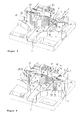
- Figur 1
- eine Vorrichtung zum Sortieren von Gebinden in einer ersten Sortierstellung,
- Figur 2
- die Vorrichtung zum Sortieren von Gebinden in einer zweiten Sortierstellung,
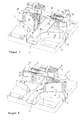
- Figur 3
- die Vorrichtung zum Sortieren von Gebinden in einer dritten Sortierstellung,
- Figur 4
- die Vorrichtung zum Sortieren von Gebinden in einer vierten Sortierstellung,
- Figur 5
- die Vorrichtung zum Sortieren von Gebinden in einer fünften Sortierstellung,
- Figur 6
- die Vorrichtung zum Sortieren von Gebinden in einer sechsten Sortierstellung,
- Figur 7
- die Vorrichtung zum Sortieren von Gebinden in einer siebten Sortierstellung und
- Figur 8
- die Vorrichtung zum Sortieren von Gebinden in einer achten Sortierstellung.
- Eine Vorrichtung 1 zum Sortieren von Gebinden wird beispielsweise zusammen mit einem Leergutrücknahmeautomaten im Einzelhandel eingesetzt, um zurückgegebene Einweg- oder Mehrwegpfandflaschen, Getränkedosen oder Getränkekisten nach der Erfassung derselben automatisiert in eine Mehrzahl von Fraktionen zu unterteilen. Hierbei werden beispielsweise Einwegpfandflaschen aus Kunststoff, Mehrwegflaschen aus Kunststoff, Mehrwegglasflaschen und Getränkekisten getrennt und unterschiedlichen Lagerorten bzw. Bevorratungsbehältnissen zugeführt. Beispielsweise können Einwegpfandflaschen aus Kunststoff nach dem Sortieren in einem Kompaktierer zerkleinert, insbesondere geschräddert oder zusammengedrückt und anschließend platzsparend bevorratet werden.
- Die Vorrichtung 1 weist als zentrale Baugruppen ein Sortiermodul 2, eine Zuführbahn 3, eine Anzahl an Abfuhrbahnen 4, 5, 6, 7, 8 sowie ein Trägermodul 9 auf, an dem die Baugruppen befestigt sind und das beispielsweise der Aufnahme nicht dargestellter Funktionseinheiten, insbesondere einer Steuereinheit zur Steuerung der Vorrichtung 1, dient. Die Zuführbahn 3 und die Abfuhrbahnen 4, 5, 6, 7, 8 sind in einer gemeinsamen Sortierebene S angeordnet. Das Sortiermodul 2 umfasst eine Antriebseinheit 10, ein erstes Stellelement 11, ein zweites Stellelement 12 sowie eine Übertragungseinheit 13 zur Übertragung einer Antriebsbewegung der Antriebseinheit 10 auf das erste Stellelement 11 und das zweite Stellelement 12. Ferner weist das Sortiermodul 2 einen ersten Stellflügel 14 und einen zweiten Stellflügel 15 auf. Die Stellflügel 14, 15 können mittels der Antriebseinheit 10 betätigt werden.
- Die Stellelemente 11, 12 sind um eine gemeinsame, senkrecht zu der Sortierebene S orientierte Schwenkachse D1 drehbar angeordnet. Das erste Stellelement 11 weist in der zu der Schwenkachse D1 senkrecht orientierten Sortierebene S eine im Wesentlichen dreieckförmige Kontur auf. Die drei Seiten bilden drei Leitflächen 16, 17, 18 des ersten Stellelements 11. Eine erste Leitfläche 16 und eine zweite Leitfläche 17 sind im Wesentlichen eben ausgebildet und rechtwinklig zueinander orientiert angeordnet. Eine die erste Leitfläche 16 und die zweite Leitfläche 17 verbindende dritte Leitfläche 18 ist im Wesentlichen konkav gekrümmt ausgebildet. Die erste Leitfläche 16 schließt mit der dritten Leitfläche 18 einen ersten spitzen Eckbereich 19 und die zweite Leitfläche 17 mit der dritten Leitfläche 18 einen zweiten spitzen Eckbereich 20 des ersten Stellelements 11 ein. Die Schwenkachse D1 ist im Bereich des rechten Winkels zwischen der ersten Leitfläche 16 und der zweiten Leitfläche 17 angeordnet. Das erste Stellelement 11 ist in der Sortierebene S symmetrisch bezüglich einer den rechten Winkel zwischen der ersten Leitfläche 16 und der zweiten Leitfläche 17 teilenden Winkelhalbierenden ausgebildet. Das zweite Stellelement 12 ist langgestreckt ausgebildet und weist in der Sortierebene S ein flügelähnliches Profil auf. Zwei gegenüberliegende Längsseiten des zweiten Stellelements 12 bilden eine erste Leitfläche 21 und eine zweite Leitfläche 22 des zweiten Stellelements 12. Die Schwenkachse D1 ist im Bereich einer ersten, die erste Leitfläche 21 mit der zweiten Leitfläche 22 verbindenden Stirnseite des zweiten Stellelements 12 angeordnet. Die der Schwenkachse D1 gegenüberliegende Stirnseite 23 des zweiten Stellelements 12 ist durch die konvex geformten Leitflächen 21, 22 des zweiten Stellelements 12 gebildet und spitz ausgeformt.
- Das erste Stellelement 11 und das zweite Stellelement 12 werden von der Antriebseinheit 10 angetrieben. Die Antriebseinheit 10 weist einen Elektromotor 24 und ein Winkelgetriebe 25 auf. Eine Antriebswelle des Elektromotors 24 ist senkrecht zu der Schwenkachse D1 der Stellelemente 11, 12 angeordnet. Das Winkelgetriebe 25 dient dazu, die Antriebsbewegung des Elektromotors 24 hinsichtlich der Parameter Drehzahl und Drehmoment anzupassen. Ferner überwindet das Winkelgetriebe 25 den 90°-Winkelversatz zwischen der Antriebswelle des Elektromotors 24 und der Schwenkachse D1 der Stellelemente 11, 12.
- Die Antriebseinheit 10 ist an einem Schlitten 26 befestigt. Der Schlitten 26 ist in zwei in eine Verstellrichtung V des Sortiermoduls 2 erstreckten Linearführungen 27 linear verschiebbar geführt. Die Verstellrichtung V des Sortiermoduls 2 erstreckt sich hierbei in der Sortierebene S des Sortiermoduls 2. Die Linearführungen 27 sind an einem Brückenträger 28 gehalten, der drei Abfuhrbahnen 6, 7, 8 beabstandet überspannt. Zwischen dem Brückenträger 28 und den drei von ihm überspannten Abfuhrbahnen 6, 7, 8 sind die Stellelemente 11, 12 angeordnet.
- Die Übertragungseinheit 13 ist zwischen dem Winkelgetriebe 25 der Antriebseinheit 10 und den Stellelementen 11, 12 angeordnet. Die Übertragungseinheit 13 weist eine Zahnstange 30 als ein erstes, linear in der Verstellrichtung V erstrecktes ortsfestes Führungsmittel und ein mit der Zahnstange 30 in Wirkverbindung stehendes Zahnrad als ein erstes rotierendes Führungsmittel auf. Die Zahnstange 30 ist fest an dem Brückenträger 28 angeordnet und definierte eine Führungsbahn 29, entlang der die Stellelemente 11, 12 linear beweglich angeordnet sind. Das erste rotierende Führungsmittel ist drehfest mit dem ersten Stellelement 11 verbunden. Ferner ist ein ebenfalls an dem Brückenträger 28 gehaltenes, nicht dargestelltes zweites ortsfestes Führungsmittel und ein drehfest mit dem zweiten Stellelement 12 verbundenes zweites rotierendes Führungsmittel angeordnet. Das zweite ortsfeste Führungsmittel ist ebenfalls als Zahnstange und das zweite rotierende Führungsmittel als Zahnrad ausgebildet. Das zweite ortsfeste Führungsmittel und das zweite rotierende Führungsmittel stehen miteinander in Eingriff.
- Eine Antriebsbewegung des Elektromotors 24 wird über das Winkelgetriebe 25 auf die Stellelemente 11, 12 übertragen. Da die Stellelemente 11, 12 über die rotierenden Führungsmittel drehfest mit einer Abtriebswelle des Winkelgetriebes 25 verbunden sind, werden die Stellelemente 11, 12 um die gemeinsame Schwenkachse D1 gedreht. Aufgrund der Wirkverbindung zwischen den rotierenden Führungsmitteln und den ortsfesten Führungsmitteln (Zahnstange 30) ist der Rotationsbewegung eine Translationsbewegung in der Verstellrichtung V des Sortiermoduls 2 überlagert. Bei dieser Translation werden die Stellelemente 11, 12 zusammen mit dem Schlitten 26 und der hieran befestigten Antriebseinheit 10 linear entlang der durch die Zahnstange 30 vorgegebenen Führungsbahn 29 verschoben. Die Übertragungseinheit 13 ist hierbei derart ausgelegt, dass die Drehbewegungen der Stellelemente 11, 12 um die Schwenkachse D1 in zwei entgegengesetzte Drehrichtungen und mit einer unterschiedlichen Drehgeschwindigkeit ausgeführt werden.
- Die Stellflügel 14, 15 sind um zwei parallele Drehachsen D2, D3 drehbar an dem Trägermodul 9 und/oder an dem Brückträger 28 gelagert. Die Drehachsen D2, D3 sind senkrecht zur Sortierebene S des Sortiermoduls 2 und parallel zur Schwenkachse D1 der Stellelemente 11, 12 orientiert. Die Stellflügel 14, 15 sind in der Sortierebene S im Wesentlichen dreieckförmig ausgebildet. Zwei der drei Dreieckseiten dienen hierbei als Leitflächen 31, 32, 33, 34 der Stellflügel 14, 15. Eine erste Leitfläche 31 des ersten Stellflügels 14 und eine erste Leitfläche 33 des zweiten Stellflügels 15 sind im Wesentlichen eben ausgebildet. Eine zweite Leitfläche 32 des ersten Stellflügels 14 und eine zweite Leitfläche 34 des zweiten Stellflügels 15 sind konkav gekrümmt. Die erste Leitfläche 31 und die zweite Leitfläche 32 des ersten Stellflügels 14 formen einen spitzen Eckbereich 35 des ersten Stellflügels 14 und die erste Leitfläche 33 und die zweite Leitfläche 34 des zweiten Stellflügels 15 einen spitzen Eckbereich 36 des zweiten Stellflügels 15. Die Drehachsen D2, D3 der Stellflügels 14, 15 sind an einem dem spitzen Eckbereich 35, 36 abgewandten Ende der eben ausgebildeten ersten Leitfläche 31, 33 der Stellflügel 14, 15 angeordnet. Bezüglich einer senkrecht zu der Sortierebene S orientierten und mittig zu der Zuführbahn 3 verlaufenden Mittelebene M des Sortiermoduls 2 sind die Stellflügel 14, 15 symmetrisch angeordnet.
- Durch Verschwenken der Stellflügel 14, 15 können die Stellflügel 14, 15 in eine von drei Schwenkstellungen verbracht werden. In einer ersten Schwenkstellung ist der erste Stellflügel 14 mit dem spitzen Eckbereich 35 desselben über eine erste Abfuhrbahn 4 geschwenkt. Der zweite Stellflügel 15 ist mit dem spitzen Eckbereich 36 desselben über eine zweite Abfuhrbahn 5 geschwenkt. In einer zweiten Schwenkstellung der Stellflügel 14, 15 sind die ersten Leitflächen 31, 33 derselben seitlich benachbart zu der ersten Abfuhrbahn 4 bzw. zu der zweiten Abfuhrbahn 5 und parallel zu derselben orientiert angeordnet. Die spitzen Eckbereiche 35, 36 der Stellflügel 14, 15 weisen hierbei einen minimalen Abstand zueinander auf und sind einander zugewandt. In einer dritten Schwenkstellung ist der spitze Eckbereich 35 des erstens Stellflügels 14 in Richtung einer dritten Abfuhrbahn 6 und der spitze Eckbereich 36 des zweiten Stellflügels 15 in Richtung einer vierten Abfuhrbahn 7 verschwenkt angeordnet. Die dritte Abfuhrbahn 6 und die vierte Abfuhrbahn 7 sind parallel auf unterschiedlichen Seiten der Mittelebene M und symmetrisch zu derselben angeordnet.
- Zum Verschwenken der Stellflügel 14, 15 wird eine erste Steuerkulisse 37 des Schlittens 26 mit einem Mitnehmernocken 38 des ersten Stellflügels 14 oder eine zweite Steuerkulisse 39 mit einem Mitnehmernocken 40 des zweiten Stellflügels 15 in Eingriff gebracht. Die Mitnehmernocken 38, 40 ragen beabstandet zu den Drehachsen D2, D3 der Stellflügel 14, 15 von denselben ab. Die Schwenkbewegungen der Stellflügel 14, 15 sind untereinander gekoppelt, so dass die Stellflügel 14, 15 stets gemeinsam in der ersten Schwenkstellung oder in der zweiten Schwenkstellung oder in der dritten Schwenkstellung angeordnet sind. Durch ein nicht dargestelltes Federelement wird bewirkt, dass die Stellflügel 14, 15 in der ersten Schwenkstellung verschwenkt angeordnet sind, sofern weder die erste Steuerkulisse 37 noch die zweite Steuerkulisse 39 mit den Mitnehmernocken 38, 40 in Eingriff stehen.
- In einer ersten Sortierstellung des Sortiermoduls 2 gemäß
Figur 1 ist das erste Stellelement 11 mit der dritten Leitfläche 18 desselben über die Zuführbahn 3 geschwenkt angeordnet. Der erste Stellflügel 14 befindet sich in der zweiten Schwenkstellung. Der zweite spitze Eckbereich 20 des ersten Stellelements 11 zeigt in Richtung der Drehachse D2 des ersten Stellflügels 14 und der Eckbereich 35 des ersten Stellflügels 14 in Richtung der Schwenkachse D1 des ersten Stellelements 11. Die dritte Leitfläche 18 des ersten Stellelements 11 und die in Transportrichtung T vor der dritten Leitfläche 18 als erstes Stellelement 11 angeordneten erste Leitfläche 31 des ersten Stellflügels 14 bilden eine gemeinsame Leitfläche, entlang derer einer auf der Zuführbahn 3 zugefördertes Gebinde in Richtung der in Bezug zur Zuführbahn 3 um 90° versetzt angeordneten ersten Abfuhrbahn 4 transportiert wird. Die in der Bewegung gekoppelten Stellflügel 14, 15 werden durch die mit dem Mitnehmernocken 40 des zweiten Stellflügels 15 zusammenwirkdende zweite Steuerkulisse 39 in der Schwenkstellung gehalten. Der zweite Stellflügel 15 und das zweite Stellelement 12, welches in Richtung der vierten Abfuhrbahn 7 zeigt, sind hierbei außer Eingriff. - Um eine möglichst umfassende und vollflächige Führung des Gebindes entlang der in Eingriff befindlichen Leitflächen 18, 31 zu erreichen und zugleich ein kollisionsfreies Verschwenken der Stellelemente 11, 12 und der Stellflügel 14, 15 sicherzustellen, sind die Leitflächen 16, 17, 18, 21, 22, 31, 32, 33, 34 zumindest teilweise durch parallel zu der Sortierebene S erstreckte und zueinander höhenversetzt angeordnete Zähne 41 und Ausnehmungen 42 gebildet. Beispielsweise greifen die in dem zweiten spitzen Eckbereich 20 angeordneten Zähne 41 des ersten Stellelements 11 in korrespondierende, das heißt höhenversetzt angeordnete Ausnehmungen 42 des ersten Stellflügels 14 und die im Eckbereich 35 des ersten Stellflügels 14 angeordneten Zähne 41 in höhenversetzt hierzu angeordnete Ausnehmungen 42 des ersten Stellelements 11 ein. Eine weitere Verbesserung der Führung der in Transportrichtung T geförderten Gebinde wird durch sich senkrecht zur Sortierebene S erstreckende passive Leiteinheiten 43 erreicht, die sicherstellen, dass ein in Transportrichtung T umzulenkendes Gebinde nicht zu einer von den Leitflächen 16, 17, 18, 21, 22, 31, 32, 33, 34 nicht gesicherten Seite von der Zuführbahn 3 oder in Abfuhrbahnen 4, 5, 6, 7, 8 geleitet.
- In einer bezüglich der Mittelebene M spiegelverkehrt zu der ersten Sortierstellung gebildeten zweiten Sortierstellung des Sortiermoduls 2 gemäß
Figur 2 wird ein auf der Zuführbahn 3 zugeführtes Gebinde entlang der über die Zuführbahn 3 geschwenkt angeordneten dritten Leitfläche 18 des ersten Stellelements 11 und der ersten Leitfläche 33 des zweiten Stellflügels 15 in Richtung der zweiten Abfuhrbahn 5 transportiert. Die in ihrer Bewegung gekoppelten Stellflügel 14, 15 werden hierbei durch die mit dem Mitnehmernocken 38 des ersten Stellflügels 14 zusammenwirkende erste Steuerkulisse 37 in der zweiten Schwenkstellung gehalten. - In einer dritten Sortierstellung des Sortiermoduls 2 gemäß
Figur 3 ist die zweite Leitfläche 17 des ersten Stellelements 11 derart über die Zuführbahn 3 geschwenkt, dass ein auf der Zuführbahn 3 gefördertes Gebinde entlang der zweiten Leitfläche 17 in Richtung der dritten Abfuhrbahn 6 transportiert wird. Es wird hierbei zwischen der zweiten Leitfläche 17 des ersten Stellelements 11 und der zweiten Leitfläche 32 des ersten Stellflügels 14 und unter dem Brückenträger 28 hindurch gefördert. Der erste Stellflügel 14 ist mit dem spitzen Eckbereich 35 derart über die erste Abfuhrbahn 4 geschwenkt, dass die erste Abfuhrbahn 4 für das Gebinde gesperrt ist und eine Fehlsortierung des Gebindes in Richtung der ersten Abfuhrbahn 4 sicher vermieden werden kann. - In einer vierten Sortierstellung des Sortiermoduls 2 gemäß
Figur 4 wird das auf der Zuführbahn 3 zugeführte Gebinde ebenfalls in Richtung der dritten Abfuhrbahn 6 gefördert. Die erste Leitfläche 21 des zweiten Stellelements 12 ist hierbei über die Zuführbahn 3 und die erste Leitfläche 16 des erstens Stellelements 11 über die zwischen der dritten Abfuhrbahn 6 und der vierten Abfuhrbahn 7 angeordnete fünfte Abfuhrbahn 8 geschwenkt, so dass das zugeführte Gebinde zunächst von der ersten Leitfläche 21 des zweiten Stellelements 12 und anschließend entlang der in Transportrichtung T vor der ersten Leitfläche 21 des zweiten Stellelements 12 angeordneten ersten Leitfläche 16 des ersten Stellelements 11 in Richtung der dritten Abfuhrbahn 6 geführt wird. Wie in der dritten Sortierstellung ist der spitze Eckbereich 35 des ersten Stellflügels 14 über die erste Abfuhrbahn 4 gesperrt und sperrt diese für das Gebinde. Beim Fördern des Gebindes von der Zuführbahn 3 auf die dritten Abfuhrbahn 6 wird das Gebinde zwischen der ersten Leitfläche 21 des zweiten Stellelements 12 und der ersten Leitfläche 16 des ersten Stellelements 11 einerseits und der zweiten Leitfläche 32 des ersten Stellflügels 14 andererseits hindurchgefördert. - Eine fünfte Sortierstellung des Sortiermoduls 2 gemäß
Figur 5 ist spiegelverkehrt bezüglich der Mittelebene M zu der dritten Sortierstellung des Sortiermoduls 2 gebildet. Ein auf der Zuführbahn 3 zugeführtes Gebinde wird hierbei entlang der über die Zuführbahn 3 geschwenkten Leitfläche 16 des ersten Stellelements 11 in Richtung der vierten Abfuhrbahn 7 geführt. Das Gebinde wird zwischen der ersten Leitfläche 16 des ersten Stellelements 11 und der zweiten Leitfläche 34 des zweiten Stellflügels 15 und unter dem Brückenträger 28 hindurch transportiert. Der zweite Stellflügel 15 wird mit dem spitzen Eckbereich 36 desselben derart über die zweite Abfuhrbahn 5 geschwenkt, dass diese für das Gebinde gesperrt ist. - Eine sechste Sortierstellung des Sortiermoduls 2 gemäß
Figur 6 ist spiegelverkehrt bezüglich der Mittelebene M zu der vierten Sortierstellung aufgebaut. Ein auf der Zuführbahn 3 zugeführtes Gebinde wird hierbei entlang der zweiten Leitfläche 22 des zweiten Stellelements 12 und des in Transportrichtung T vor der zweiten Leitfläche 22 des zweiten Stellelements 12 angeordneten zweiten Leitfläche 17 des ersten Stellelements 11 in Richtung der vierten Abfuhrbahn 7 transportiert. Die zweite Leitfläche 22 des zweiten Stellelements 12 ist hierbei über die Zuführbahn 3 und die zweite Leitfläche 17 des ersten Stellelements 11 über die fünfte Abfuhrbahn 8 geschwenkt. Der spitze Eckbereich 26 des zweiten Stellflügels 15 ist derart über die zweite Abfuhrbahn 5 geschwenkt, dass diese für das Gebinde gesperrt ist. - In einer siebten Sortierstellung des Sortiermoduls 2 gemäß
Figur 7 wird das Gebinde der in Verlängerung der Zuführbahn 3 angeordneten fünften Abfuhrbahn 8 zugeführt. Eine Umlenkung des Gebindes an einer der Leitflächen 16, 17, 18, 21, 22, 31, 32, 33, 34 ist hierbei nicht erforderlich. Das erste Stellelement 11 und das zweite Stellelement 12 sind durch Linearverschiebung des Schlittens 26 entlang der Führungsbahn 29 in Richtung des zweiten Stellflügels 15 derart benachbart zu der Zuführbahn 3 und der fünften Abfuhrbahn 8 angeordnet, dass der zweite spitze Eckbereich 20 des ersten Stellelements 11 und die spitze Stirnseite 23 des zweiten Stellelements 12 in Richtung der Zuführbahn 3 zeigen. Das erste Stellelement 11 und das zweite Stellelement 12 sind hierbei ineinander gedreht angeordnet. Die Stellflügel 14, 15 sind in der dritten Schwenkposition verbracht. In der siebten Sortierstellung ist die erste Leitfläche 16 des ersten Stellelements 11 unmittelbar benachbart zu der ersten Leitfläche 33 des zweiten Stellflügels 15 positioniert. Der zweite Stellflügel 15 blockiert in der dritten Schwenkstellung die dritte Abfuhrbahn 6. - Eine achte Sortierstellung des Sortiermoduls 2 gemäß
Figur 8 ist spiegelverkehrt bezüglich der Mittelebene M zu der siebten Sortierstellung aufgebaut. Das auf der Zuführbahn 3 zugeführte Gebinde wird ohne Umlenkung der fünften Abfuhrbahn 8 zugeführt. Das erste Stellelement 11 und das zweite Stellelement 12 sind auf der Seite des ersten Stellflügels 14 neben der Zuführbahn 3 und der fünften Abfuhrbahn 8 angeordnet. Der in der dritten Schwenkstellung positionierte zweite Stellflügel 15 sperrt in der dritten Schwenkstellung die vierte Abfuhrbahn 7. - Das Sortiermodul 2 ist aufgrund der acht unterschiedlichen Sortierpositionen und der Möglichkeit, das auf der Zuführbahn 3 zugeführte Gebinde einer von bis zu fünf Abfuhrbahnen 4, 5, 6, 7, 8 zuzuführen, äußerst flexibel einsetzbar. Da Gebinde in jeweils zwei Sortierstellungen der dritten, vierten und fünften Abfuhrbahn 6, 7, 8 zugeführt werden können, ist eine hohe Dynamik bei der Sortierung insbesondere im Hinblick auf diese Abfuhrbahnen 6, 7, 8 gegeben. Vorteilhaft können Gebinde, die häufig sortiert werden, über die dritte, vierte bzw. fünfte Abfuhrbahn 6, 7, 8 abgeführt werden. Gebinde, die seltener zurückgegeben werden, können über die erste Abfuhrbahn 4 bzw. die zweite Abfuhrbahn 5 zurückgegeben werden.
- Nach einer alternativen Ausführungsform der Erfindung können weniger als fünf Abfuhrbahnen 4, 5, 6, 7, 8 vorgesehen sein. Die zu der nicht mehr vorgesehenen Abfuhrbahn korrespondierenden Sortierstellungen des Sortiermoduls 2 werden dann nicht angefahren. Beispielsweise kann die Anordnung der Abfuhrbahnen 4, 5, 6, 7, 8 von der beispielhaft dargestellten Anordnung abweichen. Die dritte Abfuhrbahn 6, die vierte Abfuhrbahn 7 und die fünfte Abfuhrbahn 8 müssen beispielsweise nicht parallel zueinander angeordnet sein. Beispielsweise kann auf die symmetrische Anordnung der dritten und vierten Abfuhrbahn 6, 7 und der ersten und zweiten Abfuhrbahn 4, 5 verzichtet werden. Die Zuführbahn 3 und die fünfte Abfuhrbahn 8 können nach einer alternativen Ausführungsform der Erfindung durch getrennte Transportbänder realisiert werden.
- Gleiche Bauteile und Bauteilfunktionen sind durch gleiche Bezugszeichen gekennzeichnet.
- Statt einer Anordnung der Antriebswelle des Elektromotors 24 in Verstellrichtung V des Schlittens 26 kann die Antriebswelle parallel bzw. koaxial zu der Schwenkachse D1 der Stellelemente 11, 12 angeordnet sein. Ebenso kann ein ortsfester Elektromotor 24 angeordnet sein. Die rotatorische Antriebsbewegung kann dann über einen geeigneten Wandler in eine translatorische Bewegung des Schlittens 26 in Verstellrichtung V übertragen werden. Darüber hinaus kann statt eines Elektromotors 24 mit rotatorischer Antriebsbewegung beispielsweise ein Linearmotor verwendet werden.
- Nach einer alternativen Ausführungsform der Erfindung können die Stellelemente 11, 12 bzw. die Stellflügel 14, 15 durch mehr als einen Motor 24 betätigt werden. Beispielsweise kann ein erste Motor 24 die Stellelemente 11, 12 betätigen und ein zweiter Motor zum Verschwenken der Stellflügel 14, 15 vorgesehen sein. Auf eine mechanische Kopplung der Bewegung der Stellflügel 14, 15 kann verzichtet werden.
-
- 1
- Vorrichtung
- 2
- Sortiermodul
- 3
- Zuführbahn
- 4
- erste Abfuhrbahn
- 5
- zweite Abfuhrbahn
- 6
- dritte Abfuhrbahn
- 7
- vierte Abfuhrbahn
- 8
- fünfte Abfuhrbahn
- 9
- Trägermodul
- 10
- Antriebseinheit
- 11
- Stellelement
- 12
- Stellelement
- 13
- Übertragungseinheit
- 14
- Stellflügel
- 15
- Stellflügel
- 16
- Leitfläche
- 17
- Leitfläche
- 18
- Leitfläche
- 19
- Eckbereich
- 20
- Eckbereich
- 21
- Leitfläche
- 22
- Leitfläche
- 23
- Stirnseite
- 24
- Elektromotor
- 25
- Winkelgetriebe
- 26
- Schlitten
- 27
- Linearführungen
- 28
- Brückenträger
- 29
- Führungsbahn
- 30
- Zahnstange
- 31
- Leitfläche
- 32
- Leitfläche
- 33
- Leitfläche
- 34
- Leitfläche
- 35
- Eckbereich
- 36
- Eckbereich
- 37
- Steuerkulisse
- 38
- Mitnehmernocken
- 39
- Steuerkulisse
- 40
- Mitnehmernocken
- 41
- Zähne
- 42
- Ausnehmungen
- 43
- Leiteinheiten
- D1
- Schwenkachse
- D2, D3
- Drehachse
- M
- Mittelebene
- S
- Sortierebene
- T
- Transportrichtung
- V
- Verstellrichtung
Claims (10)
- Vorrichtung zum Sortieren von Gebinden mit einem Sortiermodul, das zwischen einer das Gebinde zuführenden Zuführbahn und einer Mehrzahl von Abfuhrbahnen angeordnet und mittels einer Antriebseinheit antreibbar ist,- wobei das Sortiermodul ein Stellelement mit wenigstens einer Leitfläche aufweist zur Führung des Gebindes in Richtung einer vorgegebenen Abfuhrbahn,- wobei das Stellelement senkrecht zu einer die Zuführbahn und die Abfuhrbahnen aufnehmenden Sortierebene um eine Schwenkachse drehbar angeordnet ist und- wobei eine zwischen der Antriebseinheit und dem Stellelement angeordnete Übertragungseinheit zur Übertragung einer Antriebsbewegung der Antriebseinheit auf das Stellelement derart auf das Stellelement einwirkt, dass die Schwenkachse des Stellelements unter Verdrehung derselben um die Schwenkachse entlang einer vorgegebenen Führungsbahn geführt ist zur Verbringung des Stellelements von einer ersten Sortierstellung, in der die Zuführbahn mit einer ersten Abfuhrbahn verbunden ist, in eine zweite Sortierstellung, in der die Zuführbahn mit einer zweiten Abfuhrbahn verbunden ist,
dadurch gekennzeichnet, dass dem entlang der Führungsbahn (29) geführten Stellelement (11, 12) ein ortsfest angeordneter, um eine Drehachse (D2, D3) schwenkbarer Stellflügel (14, 15) mit wenigstens einer zusätzlichen Leitfläche (31, 32, 33, 34) zugeordnet ist. - Vorrichtung nach Anspruch 1, dadurch gekennzeichnet, dass sich die Führungsbahn (29) in eine Verstellrichtung (V) des Sortiermoduls (2) linear erstreckt.
- Vorrichtung nach Anspruch 1 oder 2, dadurch gekennzeichnet, dass die Übertragungseinheit (13) ein linear in der Verstellrichtung (V) erstrecktes, ortsfestes Führungsmittel (Zahnstange 30) und ein koaxial zu der Schwenkachse (D1 ) des Stellelements (11, 12) angeordnetes, mit dem Stellelement (11, 12) in Wirkverbindung stehendes rotierendes Führungsmittel aufweist und dass das ortsfeste Führungsmittel (Zahnstange 30) und das rotierende Führungsmittel derart zusammenwirken, dass das Stellelement (11, 12) bei Rotation desselben um die Schwenkachse (D1) entlang der Führungsbahn (29) linear bewegbar geführt ist.
- Vorrichtung nach einem der Ansprüche 1 bis 3, dadurch gekennzeichnet, dass die Antriebseinheit (10) und/oder die Stelleinheit (11, 12) und/oder das rotierende Führungsmittel an einem entlang der Führungsbahn (29) linear bewegbaren Schlitten (26) befestigt sind.
- Vorrichtung nach einem der Ansprüche 1 bis 4, dadurch gekennzeichnet, dass das Sortiermodul (2) eine in der Verstellrichtung (V) verschiebbar angeordnete Steuerkontur (37, 39) aufweist zum Betätigen des Stellflügels (14, 15) und zum Verschwenken desselben von einer ersten Schwenkstellung in wenigstens eine zweite Schwenkstellung.
- Vorrichtung nach einem der Ansprüche 1 bis 5, dadurch gekennzeichnet, dass zwei Stellelemente (11, 12) angeordnet sind, die um eine gemeinsame Schwenkachse (D1), jedoch in entgegengesetzte Drehrichtungen drehbar gelagert sind.
- Vorrichtung nach einem der Ansprüche 1 bis 6, dadurch gekennzeichnet, dass ein erstes Stellelement (11) in der zu der Schwenkachse (D1) senkrecht orientierten Sortierebene (S) eine im Wesentlichen dreieckförmige Kontur aufweist, wobei die Dreieckseiten jeweils eine Leitfläche (16, 17, 18) bilden, von der ein erste Leitfläche (16) und eine zu der ersten Leitfläche (16) rechtwinklig orientierte zweite Leitfläche (17) im Wesentlichen eben ausgebildet sind und von der eine die erste Leitfläche (16) und die zweite Leitfläche (17) verbindende dritte Leitfläche (18) im Wesentlichen konkav gekrümmt ausgebildet ist, und dass das zweite Stellelement (12) im Wesentlichen langgestreckt ausgebildet ist mit zwei gegenüberliegenden Längsseiten als zwei Leitflächen (21, 22).
- Vorrichtung nach einem der Ansprüche 1 bis 7, dadurch gekennzeichnet, dass das Sortiermodul (2) zwei Stellflügel (14, 15) aufweist und dass das wenigstens eine Stellelement (11, 12) in Verstellrichtung (V) zwischen den beiden Stellflügeln (14, 15) angeordnet ist.
- Vorrichtung nach einem der Ansprüche 1 bis 8, dadurch gekennzeichnet, dass die Stellflügel (14, 15) in der Sortierebene (S) im Wesentlichen dreieckförmig ausgebildet sind, wobei eine ersten Dreieckseite im Wesentlichen eben ausgebildet ist und als eine erste Leitfläche (31, 33) des Stellflügels (14, 15) dient und wobei eine zweite Dreieckseite, die mit der ersten Leitfläche (31, 33) einen spitzen Eckbereich (35, 36) bildet, im Wesentlichen konkav gekrümmt ausgebildet ist und als eine zweite Leitfläche (32, 34) dient.
- Vorrichtung nach einem der Ansprüche 1 bis 9, dadurch gekennzeichnet, dass ein dem dreieckförmigen ersten Stellelement (11) zugeordnetes erstes lineares Führungsmittel (Zahnstange 30) derart auf ein drehfest mit dem dreieckförmigen ersten Stellelement (11) verbundenen ersten rotierenden Führungsmittel und ein dem langgestreckten zweiten Stellelement (12) zugeordnetes zweites lineares Führungsmittel derart auf ein drehfest mit dem langgestreckten zweiten Stellelement (12) zugeordneten zweiten rotierenden Führungsmittel einwirken und dass eine erste Steuerkontur (37) des Sortiermoduls (2) derart mit einem ersten Mitnehmernocken (38) des ersten Stellflügels (14) und eine zweite Steuerkontur (39) des Sortiermoduls (2) derart mit einem Mitnehmernocken (40) des zweiten Stellflügels (15) zusammenwirken und dass die Leitflächen (16, 17, 18) des ersten Stellelements (11) und die Leitflächen (21, 22) des zweiten Stellelements (12) und die Leitflächen (31, 32) des ersten Stellflügels (14) und die Leitflächen (33, 34) des zweiten Stellflügels(15) derart höhenversetzt zueinander angeordnete, sich senkrecht zu der Schwenkachse (D2, D3) erstreckende Ausnehmungen (42) und Zähne (41) aufweisen, dass das Gebinde in Abhängigkeit von der Drehstellung des Sortiermoduls (2)- in einer ersten Sortierstellung entlang der über die Zuführbahn (3) geschwenkten dritten Leitfläche (18) des ersten Stellelements (11 ) und der in einer Transportrichtung (T) des Gebindes vor der dritten Leitfläche (18) des ersten Stellelements (11 ) angeordneten ersten Leitfläche (31) des ersten Stellflügels (14) einer ersten Abfuhrbahn (4) zuführbar ist,- in einer zweiten Sortierstellung entlang der über die Zuführbahn (3) geschwenkten dritten Leitfläche (18) des ersten Stellelements (11) und der in Transportrichtung (T) vor der dritten Leitfläche (18) des ersten Stellelements (11) angeordneten ersten Leitfläche (33) des zweiten Stellflügels (15) einer zweiten Abfuhrbahn (5) zuführbar ist,- in einer dritten Sortierstellung entlang der über die Zuführbahn (3) geschwenkten zweiten Leitfläche (17) des ersten Stellelements (11) und zwischen der zweiten Leitfläche (17) des ersten Stellelements (11) und der zweiten Leitfläche (32) des ersten Stellflügels (14) hindurch einer dritten Abfuhrbahn (6) zuführbar ist,- in einer vierten Sortierstellung entlang der über die Zuführbahn (3) geschwenkten ersten Leitfläche (21) des zweiten Stellelements (12) und der in Transportrichtung (T) vor der ersten Leitfläche (21) des zweiten Stellelements (12) angeordneten ersten Leitfläche (16) des ersten Stellelements (11) und zwischen der ersten Leitfläche (21) des zweiten Stellelements (12) und der ersten Leitfläche (16) des ersten Stellelements (11) einerseits und der zweiten Leitfläche (32) des ersten Stellflügels (14) andererseits hindurch der dritten Abfuhrbahn (6) zuführbar ist,- in einer fünften Sortierstellung entlang der über die Zuführbahn (3) geschwenkten ersten Leitfläche (16) des ersten Stellelements (11 ) und zwischen der ersten Leitfläche (16) des ersten Stellelements (11 ) und der zweiten Leitfläche (34) des zweiten Stellflügels (15) hindurch einer vierten Abfuhrbahn (7) zuführbar ist,- in einer sechsten Sortierstellung entlang der über die Zuführbahn (3) geschwenkten zweiten Leitfläche (22) des zweiten Stellelements (12) und der in Transportrichtung (T) vor der zweiten Leitfläche (22) des zweiten Stellelements (12) angeordneten zweiten Leitfläche (17) des ersten Stellelements (11) und zwischen der zweiten Leitfläche (22) des zweiten Stellelements (12) und der zweiten Leitfläche (17) des ersten Stellelements (11) einerseits und der zweiten Leitfläche (34) des zweiten Stellflügels (15) andererseits hindurch der vierten Abfuhrbahn (7) zuführbar ist,- in einer siebten Sortierstellung einer in Verlängerung der Zuführbahn (3) angeordneten fünften Abfuhrbahn (8) zuführbar ist, wobei das erste Stellelement (11) und das zweite Stellelement (12) auf einer dem zweiten Stellflügel (15) zugeordneten Seite benachbart zu der Zuführbahn (3) und der fünften Abfuhrbahn (8) angeordnet sind, und- in einer achten Sortierstellung der in Verlängerung der Zuführbahn (3) angeordneten fünften Abfuhrbahn (8) zuführbar ist, wobei das erste Stellelement (11) und das zweite Stellelement (12) auf einer dem ersten Stellflügel (14) zugeordneten Seite benachbart zu der Zuführbahn (3) und der fünften Abfuhrbahn (8) angeordnet sind.
Applications Claiming Priority (1)
| Application Number | Priority Date | Filing Date | Title |
|---|---|---|---|
| DE102009044870A DE102009044870A1 (de) | 2009-12-11 | 2009-12-11 | Vorrichtung zum Sortieren von Gebinden |
Publications (2)
| Publication Number | Publication Date |
|---|---|
| EP2332866A1 true EP2332866A1 (de) | 2011-06-15 |
| EP2332866B1 EP2332866B1 (de) | 2012-08-22 |
Family
ID=43743547
Family Applications (1)
| Application Number | Title | Priority Date | Filing Date |
|---|---|---|---|
| EP20100401176 Not-in-force EP2332866B1 (de) | 2009-12-11 | 2010-10-15 | Vorrichtung zum Sortieren von Gebinden |
Country Status (3)
| Country | Link |
|---|---|
| EP (1) | EP2332866B1 (de) |
| DE (1) | DE102009044870A1 (de) |
| DK (1) | DK2332866T3 (de) |
Cited By (3)
| Publication number | Priority date | Publication date | Assignee | Title |
|---|---|---|---|---|
| CN103449156A (zh) * | 2013-09-03 | 2013-12-18 | 武汉人天包装技术有限公司 | 托盘输送换向装置 |
| EP3473423A1 (de) * | 2017-10-23 | 2019-04-24 | Wincor Nixdorf International GmbH | Kompaktoranordnung, kompaktoreinrichtung und verfahren zum montieren einer kompaktoranordnung |
| CN110254810A (zh) * | 2019-06-27 | 2019-09-20 | 芜湖市恒浩机械制造有限公司 | 一种应用于汽车活塞包装用的三等分输送装置 |
Citations (2)
| Publication number | Priority date | Publication date | Assignee | Title |
|---|---|---|---|---|
| US4441604A (en) * | 1982-06-24 | 1984-04-10 | Bae Automated Systems, Inc. | Pusher mechanism |
| US4643291A (en) * | 1986-01-21 | 1987-02-17 | Rexnord Inc. | Linear articulated pusher |
Family Cites Families (4)
| Publication number | Priority date | Publication date | Assignee | Title |
|---|---|---|---|---|
| WO1995018053A1 (en) * | 1993-12-28 | 1995-07-06 | Unilever Plc | Lane distribution apparatus |
| DE10055207B4 (de) | 2000-11-07 | 2012-08-30 | Wincor Nixdorf International Gmbh | Flaschen-Rücknahmeautomat |
| DE102008047279A1 (de) * | 2008-09-16 | 2010-04-15 | Wincor Nixdorf International Gmbh | Vorrichtung zum Sortieren von Behältern |
| DE102009011716A1 (de) | 2009-03-04 | 2010-09-09 | Wincor Nixdorf International Gmbh | Vorrichtung zum Sortieren von Gebinden |
-
2009
- 2009-12-11 DE DE102009044870A patent/DE102009044870A1/de not_active Withdrawn
-
2010
- 2010-10-15 DK DK10401176T patent/DK2332866T3/da active
- 2010-10-15 EP EP20100401176 patent/EP2332866B1/de not_active Not-in-force
Patent Citations (2)
| Publication number | Priority date | Publication date | Assignee | Title |
|---|---|---|---|---|
| US4441604A (en) * | 1982-06-24 | 1984-04-10 | Bae Automated Systems, Inc. | Pusher mechanism |
| US4643291A (en) * | 1986-01-21 | 1987-02-17 | Rexnord Inc. | Linear articulated pusher |
Cited By (4)
| Publication number | Priority date | Publication date | Assignee | Title |
|---|---|---|---|---|
| CN103449156A (zh) * | 2013-09-03 | 2013-12-18 | 武汉人天包装技术有限公司 | 托盘输送换向装置 |
| EP3473423A1 (de) * | 2017-10-23 | 2019-04-24 | Wincor Nixdorf International GmbH | Kompaktoranordnung, kompaktoreinrichtung und verfahren zum montieren einer kompaktoranordnung |
| WO2019081423A1 (de) * | 2017-10-23 | 2019-05-02 | Wincor Nixdorf International Gmbh | Kompaktoranordnung, kompaktoreinrichtung und verfahren zum montieren einer kompaktoranordnung |
| CN110254810A (zh) * | 2019-06-27 | 2019-09-20 | 芜湖市恒浩机械制造有限公司 | 一种应用于汽车活塞包装用的三等分输送装置 |
Also Published As
| Publication number | Publication date |
|---|---|
| EP2332866B1 (de) | 2012-08-22 |
| DK2332866T3 (da) | 2012-12-17 |
| DE102009044870A1 (de) | 2011-06-16 |
Similar Documents
| Publication | Publication Date | Title |
|---|---|---|
| EP1935811B1 (de) | Luftförderer für Behältnisse | |
| EP3136867B1 (de) | Verfahren und vorrichtung zur erzeugung von zuschnitten von teigstücken aus einer oder mehreren teigbahnen | |
| EP3260399A1 (de) | Greifvorrichtung zum erfassen mehrerer stückgüter, system zum umgang mit mehreren stückgütern und verfahren zum manipulieren mehrerer stückgüter | |
| DE102007037250A1 (de) | Vorrichtung zum Transportieren von Gebinden | |
| EP2226770B1 (de) | Vorrichtung zum Sortieren von Gebinden | |
| DE10301178B4 (de) | Vorrichtung zum Ausrichten und Verteilen | |
| EP0576390A1 (de) | Vorrichtung zum Sammeln von Einzelblättern zu einem Bund | |
| EP3431422A1 (de) | Greifeinrichtung für einen manipulator und verfahren zum ausrüsten einer für einen manipulator vorgesehenen greifeinrichtung | |
| DE2039697C3 (de) | Mehrstufige Formmaschine, insbesondere Mehrstufenpresse | |
| DE69505042T2 (de) | Übertragungsvorrichtung, insbesondere in Zigaretten- Verpackungsmaschinen | |
| EP2332866B1 (de) | Vorrichtung zum Sortieren von Gebinden | |
| EP2964550B1 (de) | Vorrichtung zur positionierung und/oder ausrichtung ein oder mehrerer verstellbarer leitkomponenten zur führung von artikeln in einem transportsystem | |
| EP2657915B1 (de) | Vorrichtung und Verfahren zum seriellen Bedrucken von Druckmedien | |
| DE102014103827A1 (de) | Antriebsvorrichtung zum Antrieb eines Werkzeugschiebers in einer Falzanlage | |
| EP2292536A2 (de) | Transportvorrichtung zum Transportieren von Gefäßverschlüssen | |
| EP2119569B1 (de) | Sammelhefter mit variabler Kettenteilung | |
| EP3030370B1 (de) | Plattenaufteilanlage | |
| EP2433732B1 (de) | Plattenaufteilanlage sowie Verfahren zu deren Betreiben | |
| DE20214860U1 (de) | Bandförderer mit Ausschleuseinrichtung | |
| DE102010017416B4 (de) | Vorrichtung zum Sortieren von Gebinden | |
| EP2228141B1 (de) | Vorrichtung zum Sortieren von Gebinden | |
| DE102013221002B4 (de) | Vorrichtung zur Ausrichtung von Doppelteiglingen | |
| DE102022100904A1 (de) | Verteilförderer zum Verteilen von Gebinden | |
| WO2019037896A1 (de) | Längsschneidevorrichtung | |
| EP3081330B1 (de) | Vorrichtung zum einsetzen von werkstücken oder werkzeugen in eine werkzeugmaschine |
Legal Events
| Date | Code | Title | Description |
|---|---|---|---|
| PUAI | Public reference made under article 153(3) epc to a published international application that has entered the european phase |
Free format text: ORIGINAL CODE: 0009012 |
|
| AK | Designated contracting states |
Kind code of ref document: A1 Designated state(s): AL AT BE BG CH CY CZ DE DK EE ES FI FR GB GR HR HU IE IS IT LI LT LU LV MC MK MT NL NO PL PT RO RS SE SI SK SM TR |
|
| AX | Request for extension of the european patent |
Extension state: BA ME |
|
| 17P | Request for examination filed |
Effective date: 20111104 |
|
| GRAP | Despatch of communication of intention to grant a patent |
Free format text: ORIGINAL CODE: EPIDOSNIGR1 |
|
| RIC1 | Information provided on ipc code assigned before grant |
Ipc: B07C 5/12 20060101ALI20120104BHEP Ipc: G07F 7/06 20060101ALI20120104BHEP Ipc: B65G 47/76 20060101AFI20120104BHEP |
|
| GRAS | Grant fee paid |
Free format text: ORIGINAL CODE: EPIDOSNIGR3 |
|
| GRAA | (expected) grant |
Free format text: ORIGINAL CODE: 0009210 |
|
| AK | Designated contracting states |
Kind code of ref document: B1 Designated state(s): AL AT BE BG CH CY CZ DE DK EE ES FI FR GB GR HR HU IE IS IT LI LT LU LV MC MK MT NL NO PL PT RO RS SE SI SK SM TR |
|
| REG | Reference to a national code |
Ref country code: GB Ref legal event code: FG4D Free format text: NOT ENGLISH |
|
| REG | Reference to a national code |
Ref country code: CH Ref legal event code: EP |
|
| REG | Reference to a national code |
Ref country code: IE Ref legal event code: FG4D Free format text: LANGUAGE OF EP DOCUMENT: GERMAN |
|
| REG | Reference to a national code |
Ref country code: AT Ref legal event code: REF Ref document number: 571864 Country of ref document: AT Kind code of ref document: T Effective date: 20120915 |
|
| REG | Reference to a national code |
Ref country code: DE Ref legal event code: R096 Ref document number: 502010001161 Country of ref document: DE Effective date: 20121018 |
|
| REG | Reference to a national code |
Ref country code: CH Ref legal event code: NV Representative=s name: FIAMMENGHI-FIAMMENGHI, CH |
|
| REG | Reference to a national code |
Ref country code: SE Ref legal event code: TRGR |
|
| REG | Reference to a national code |
Ref country code: DK Ref legal event code: T3 |
|
| REG | Reference to a national code |
Ref country code: NL Ref legal event code: VDEP Effective date: 20120822 |
|
| REG | Reference to a national code |
Ref country code: LT Ref legal event code: MG4D Effective date: 20120822 |
|
| PG25 | Lapsed in a contracting state [announced via postgrant information from national office to epo] |
Ref country code: LT Free format text: LAPSE BECAUSE OF FAILURE TO SUBMIT A TRANSLATION OF THE DESCRIPTION OR TO PAY THE FEE WITHIN THE PRESCRIBED TIME-LIMIT Effective date: 20120822 Ref country code: NO Free format text: LAPSE BECAUSE OF FAILURE TO SUBMIT A TRANSLATION OF THE DESCRIPTION OR TO PAY THE FEE WITHIN THE PRESCRIBED TIME-LIMIT Effective date: 20121122 Ref country code: IS Free format text: LAPSE BECAUSE OF FAILURE TO SUBMIT A TRANSLATION OF THE DESCRIPTION OR TO PAY THE FEE WITHIN THE PRESCRIBED TIME-LIMIT Effective date: 20121222 Ref country code: HR Free format text: LAPSE BECAUSE OF FAILURE TO SUBMIT A TRANSLATION OF THE DESCRIPTION OR TO PAY THE FEE WITHIN THE PRESCRIBED TIME-LIMIT Effective date: 20120822 |
|
| PG25 | Lapsed in a contracting state [announced via postgrant information from national office to epo] |
Ref country code: GR Free format text: LAPSE BECAUSE OF FAILURE TO SUBMIT A TRANSLATION OF THE DESCRIPTION OR TO PAY THE FEE WITHIN THE PRESCRIBED TIME-LIMIT Effective date: 20121123 Ref country code: LV Free format text: LAPSE BECAUSE OF FAILURE TO SUBMIT A TRANSLATION OF THE DESCRIPTION OR TO PAY THE FEE WITHIN THE PRESCRIBED TIME-LIMIT Effective date: 20120822 Ref country code: SI Free format text: LAPSE BECAUSE OF FAILURE TO SUBMIT A TRANSLATION OF THE DESCRIPTION OR TO PAY THE FEE WITHIN THE PRESCRIBED TIME-LIMIT Effective date: 20120822 Ref country code: PT Free format text: LAPSE BECAUSE OF FAILURE TO SUBMIT A TRANSLATION OF THE DESCRIPTION OR TO PAY THE FEE WITHIN THE PRESCRIBED TIME-LIMIT Effective date: 20121224 |
|
| PG25 | Lapsed in a contracting state [announced via postgrant information from national office to epo] |
Ref country code: NL Free format text: LAPSE BECAUSE OF FAILURE TO SUBMIT A TRANSLATION OF THE DESCRIPTION OR TO PAY THE FEE WITHIN THE PRESCRIBED TIME-LIMIT Effective date: 20120822 |
|
| BERE | Be: lapsed |
Owner name: WINCOR NIXDORF INTERNATIONAL G.M.B.H. Effective date: 20121031 |
|
| PG25 | Lapsed in a contracting state [announced via postgrant information from national office to epo] |
Ref country code: EE Free format text: LAPSE BECAUSE OF FAILURE TO SUBMIT A TRANSLATION OF THE DESCRIPTION OR TO PAY THE FEE WITHIN THE PRESCRIBED TIME-LIMIT Effective date: 20120822 Ref country code: CZ Free format text: LAPSE BECAUSE OF FAILURE TO SUBMIT A TRANSLATION OF THE DESCRIPTION OR TO PAY THE FEE WITHIN THE PRESCRIBED TIME-LIMIT Effective date: 20120822 Ref country code: RO Free format text: LAPSE BECAUSE OF FAILURE TO SUBMIT A TRANSLATION OF THE DESCRIPTION OR TO PAY THE FEE WITHIN THE PRESCRIBED TIME-LIMIT Effective date: 20120822 Ref country code: ES Free format text: LAPSE BECAUSE OF FAILURE TO SUBMIT A TRANSLATION OF THE DESCRIPTION OR TO PAY THE FEE WITHIN THE PRESCRIBED TIME-LIMIT Effective date: 20121203 |
|
| PG25 | Lapsed in a contracting state [announced via postgrant information from national office to epo] |
Ref country code: IT Free format text: LAPSE BECAUSE OF FAILURE TO SUBMIT A TRANSLATION OF THE DESCRIPTION OR TO PAY THE FEE WITHIN THE PRESCRIBED TIME-LIMIT Effective date: 20120822 Ref country code: MC Free format text: LAPSE BECAUSE OF NON-PAYMENT OF DUE FEES Effective date: 20121031 Ref country code: PL Free format text: LAPSE BECAUSE OF FAILURE TO SUBMIT A TRANSLATION OF THE DESCRIPTION OR TO PAY THE FEE WITHIN THE PRESCRIBED TIME-LIMIT Effective date: 20120822 Ref country code: SK Free format text: LAPSE BECAUSE OF FAILURE TO SUBMIT A TRANSLATION OF THE DESCRIPTION OR TO PAY THE FEE WITHIN THE PRESCRIBED TIME-LIMIT Effective date: 20120822 |
|
| PLBE | No opposition filed within time limit |
Free format text: ORIGINAL CODE: 0009261 |
|
| STAA | Information on the status of an ep patent application or granted ep patent |
Free format text: STATUS: NO OPPOSITION FILED WITHIN TIME LIMIT |
|
| REG | Reference to a national code |
Ref country code: IE Ref legal event code: MM4A |
|
| 26N | No opposition filed |
Effective date: 20130523 |
|
| PG25 | Lapsed in a contracting state [announced via postgrant information from national office to epo] |
Ref country code: RS Free format text: LAPSE BECAUSE OF FAILURE TO SUBMIT A TRANSLATION OF THE DESCRIPTION OR TO PAY THE FEE WITHIN THE PRESCRIBED TIME-LIMIT Effective date: 20120822 Ref country code: IE Free format text: LAPSE BECAUSE OF NON-PAYMENT OF DUE FEES Effective date: 20121015 Ref country code: BG Free format text: LAPSE BECAUSE OF FAILURE TO SUBMIT A TRANSLATION OF THE DESCRIPTION OR TO PAY THE FEE WITHIN THE PRESCRIBED TIME-LIMIT Effective date: 20121122 Ref country code: BE Free format text: LAPSE BECAUSE OF NON-PAYMENT OF DUE FEES Effective date: 20121031 |
|
| REG | Reference to a national code |
Ref country code: DE Ref legal event code: R097 Ref document number: 502010001161 Country of ref document: DE Effective date: 20130523 |
|
| PG25 | Lapsed in a contracting state [announced via postgrant information from national office to epo] |
Ref country code: CY Free format text: LAPSE BECAUSE OF FAILURE TO SUBMIT A TRANSLATION OF THE DESCRIPTION OR TO PAY THE FEE WITHIN THE PRESCRIBED TIME-LIMIT Effective date: 20120822 Ref country code: AL Free format text: LAPSE BECAUSE OF FAILURE TO SUBMIT A TRANSLATION OF THE DESCRIPTION OR TO PAY THE FEE WITHIN THE PRESCRIBED TIME-LIMIT Effective date: 20120822 Ref country code: MT Free format text: LAPSE BECAUSE OF FAILURE TO SUBMIT A TRANSLATION OF THE DESCRIPTION OR TO PAY THE FEE WITHIN THE PRESCRIBED TIME-LIMIT Effective date: 20120822 |
|
| PG25 | Lapsed in a contracting state [announced via postgrant information from national office to epo] |
Ref country code: TR Free format text: LAPSE BECAUSE OF FAILURE TO SUBMIT A TRANSLATION OF THE DESCRIPTION OR TO PAY THE FEE WITHIN THE PRESCRIBED TIME-LIMIT Effective date: 20120822 |
|
| PG25 | Lapsed in a contracting state [announced via postgrant information from national office to epo] |
Ref country code: LU Free format text: LAPSE BECAUSE OF NON-PAYMENT OF DUE FEES Effective date: 20121015 Ref country code: SM Free format text: LAPSE BECAUSE OF FAILURE TO SUBMIT A TRANSLATION OF THE DESCRIPTION OR TO PAY THE FEE WITHIN THE PRESCRIBED TIME-LIMIT Effective date: 20120822 |
|
| PG25 | Lapsed in a contracting state [announced via postgrant information from national office to epo] |
Ref country code: HU Free format text: LAPSE BECAUSE OF FAILURE TO SUBMIT A TRANSLATION OF THE DESCRIPTION OR TO PAY THE FEE WITHIN THE PRESCRIBED TIME-LIMIT Effective date: 20101015 |
|
| PG25 | Lapsed in a contracting state [announced via postgrant information from national office to epo] |
Ref country code: MK Free format text: LAPSE BECAUSE OF FAILURE TO SUBMIT A TRANSLATION OF THE DESCRIPTION OR TO PAY THE FEE WITHIN THE PRESCRIBED TIME-LIMIT Effective date: 20120822 |
|
| REG | Reference to a national code |
Ref country code: FR Ref legal event code: PLFP Year of fee payment: 7 |
|
| REG | Reference to a national code |
Ref country code: FR Ref legal event code: PLFP Year of fee payment: 8 |
|
| REG | Reference to a national code |
Ref country code: FR Ref legal event code: PLFP Year of fee payment: 9 |
|
| PGFP | Annual fee paid to national office [announced via postgrant information from national office to epo] |
Ref country code: CH Payment date: 20200917 Year of fee payment: 11 |
|
| REG | Reference to a national code |
Ref country code: DE Ref legal event code: R082 Ref document number: 502010001161 Country of ref document: DE Representative=s name: VIERING, JENTSCHURA & PARTNER MBB PATENT- UND , DE Ref country code: DE Ref legal event code: R082 Ref document number: 502010001161 Country of ref document: DE Representative=s name: KILBURN & STRODE LLP, NL |
|
| REG | Reference to a national code |
Ref country code: CH Ref legal event code: PL |
|
| REG | Reference to a national code |
Ref country code: DE Ref legal event code: R082 Ref document number: 502010001161 Country of ref document: DE Representative=s name: VIERING, JENTSCHURA & PARTNER MBB PATENT- UND , DE |
|
| PG25 | Lapsed in a contracting state [announced via postgrant information from national office to epo] |
Ref country code: LI Free format text: LAPSE BECAUSE OF NON-PAYMENT OF DUE FEES Effective date: 20211031 Ref country code: CH Free format text: LAPSE BECAUSE OF NON-PAYMENT OF DUE FEES Effective date: 20211031 |
|
| PGFP | Annual fee paid to national office [announced via postgrant information from national office to epo] |
Ref country code: FR Payment date: 20221020 Year of fee payment: 13 |
|
| PGFP | Annual fee paid to national office [announced via postgrant information from national office to epo] |
Ref country code: SE Payment date: 20221020 Year of fee payment: 13 Ref country code: GB Payment date: 20221024 Year of fee payment: 13 Ref country code: FI Payment date: 20221018 Year of fee payment: 13 Ref country code: DK Payment date: 20221021 Year of fee payment: 13 Ref country code: DE Payment date: 20220916 Year of fee payment: 13 Ref country code: AT Payment date: 20221018 Year of fee payment: 13 |
|
| REG | Reference to a national code |
Ref country code: DE Ref legal event code: R119 Ref document number: 502010001161 Country of ref document: DE |
|
| REG | Reference to a national code |
Ref country code: SE Ref legal event code: EUG |
|
| REG | Reference to a national code |
Ref country code: DK Ref legal event code: EBP Effective date: 20231031 |
|
| REG | Reference to a national code |
Ref country code: AT Ref legal event code: MM01 Ref document number: 571864 Country of ref document: AT Kind code of ref document: T Effective date: 20231015 |
|
| GBPC | Gb: european patent ceased through non-payment of renewal fee |
Effective date: 20231015 |
|
| PG25 | Lapsed in a contracting state [announced via postgrant information from national office to epo] |
Ref country code: GB Free format text: LAPSE BECAUSE OF NON-PAYMENT OF DUE FEES Effective date: 20231015 |
|
| PG25 | Lapsed in a contracting state [announced via postgrant information from national office to epo] |
Ref country code: AT Free format text: LAPSE BECAUSE OF NON-PAYMENT OF DUE FEES Effective date: 20231015 |
|
| PG25 | Lapsed in a contracting state [announced via postgrant information from national office to epo] |
Ref country code: GB Free format text: LAPSE BECAUSE OF NON-PAYMENT OF DUE FEES Effective date: 20231015 Ref country code: FR Free format text: LAPSE BECAUSE OF NON-PAYMENT OF DUE FEES Effective date: 20231031 Ref country code: FI Free format text: LAPSE BECAUSE OF NON-PAYMENT OF DUE FEES Effective date: 20231015 Ref country code: DE Free format text: LAPSE BECAUSE OF NON-PAYMENT OF DUE FEES Effective date: 20240501 Ref country code: AT Free format text: LAPSE BECAUSE OF NON-PAYMENT OF DUE FEES Effective date: 20231015 |
|
| PG25 | Lapsed in a contracting state [announced via postgrant information from national office to epo] |
Ref country code: SE Free format text: LAPSE BECAUSE OF NON-PAYMENT OF DUE FEES Effective date: 20231016 |
|
| PG25 | Lapsed in a contracting state [announced via postgrant information from national office to epo] |
Ref country code: DK Free format text: LAPSE BECAUSE OF NON-PAYMENT OF DUE FEES Effective date: 20231031 |
|
| PG25 | Lapsed in a contracting state [announced via postgrant information from national office to epo] |
Ref country code: DK Free format text: LAPSE BECAUSE OF NON-PAYMENT OF DUE FEES Effective date: 20231031 |